

OSD Audio OSD2051 Owner's Manual
Doc. ID 10109204
OPERATOR MANUAL
OSD2051
10/100Base-Tx to 100Base-Fx
MEDIA CONVERTER
The OSD2051 is designed to convert between
10/100Base-Tx copper cabling and 100Base-Fx fiber via
the SFP port. Operation over at least 40km of singlemode
fiber is possible by use of the appropriate optical devices.
The unit operates over one or two fibers depending on the
SFP used. It is equipped with one SFP port, one RJ45
and power jack. For ease of network monitoring and fault
isolation the OSD2051 has 4 indicators (see tables).
Specifications and Features
▲
Complies with the IEEE 802.3 standard.
▲
Supports network traffic of 10 or 100Mbps.
▲
Automatic TP setup: no need for crossover
cables
▲
Auto-sensing of half or full duplex operation.
▲
Automatic set up for 10 or 100Mbps on copper
side.
▲
A very compact design that fits in the camera
housing
▲
Available for singlemode, multimode operation
over a variety of link budgets
▲
Available for operation over 1 or 2 fibers
▲
Powered by non-critical 12VDC or 24VAC
supplies
▲
Operates over –20 to +75°C temperature range
▲
Utilizes 10/100Base-Fx SFP transceivers that
can be selected according to specific length or
fiber requirements without changing the whole
unit
Fitting SFP Connectors
Care should be taken when inserting/removing the SFP
connectors as SFP modules are Electrostatic (ES) sensitive and
Electrostatic Discharge (ESD) precautions should be taken
when installing. Ensure that the SFP is fully engaged and
latched into position.
Inserting SFP – Ensure that the SFP lever is in the locked
position and insert into SFP port. Gently push the SFP until it
locks into place. Remove dust cap and fit fiber cable.
Removing SFP – Remove fiber connector. Pull the SFP lever
down to unlock SFP from housing. Using the lever, gently pull
the SFP out.
Case Dimensions and Mounting Details
Below is an outer case drawing showing the dimensions.
The OSD2051 can be mounted on the optional mounting base
clips by simply utilizing the OSD2051 ribbed edge. Dimensions
below
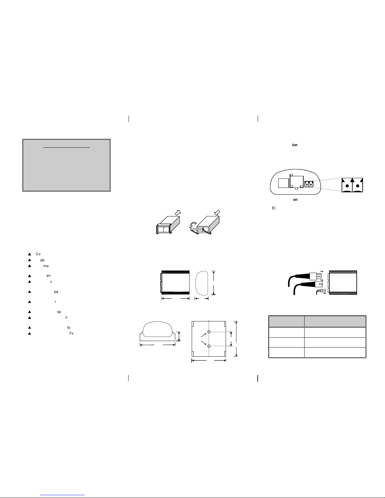
Power Connection
The voltage range of the OSD2051 is 8V
DC
to 35VDC or 22 to
28V
AC
@ 3VA. Connect power to the connector located at the
front of the case (see diagram).
Signal Connection
Ethernet cable should be connected to the RJ45 Copper
connector on the OSD2051. The appropriate SFP
connector should be inserted into the SFP port.
The optical fiber cable must be terminated with the
appropriate type optical connector (SC for single fiber and
LC for 2 fiber). Before connection, inspect the ends of the
connectors to ensure that no dust or dirt is present as it
could contaminate the modem connector and result in poor
performance.
If it is necessary to clean the cable connectors use
isopropyl alcohol and lint free tissue to remove
contamination.
SFP Port Options
OSD Part
Number
SFP Description
SFP10/100LFx
2 fiber SFP plug-in transceiver @
1310nm
SFP10/100WLFxA
1 fiber SFP plug-in transceiver (Tx
@ 1310nm, Rx @ 1550nm)
SFP10/100WLFxB
1 fiber SFP plug-in transceiver (Tx
@ 1550nm, Rx @ 1310nm)
Inserting
SFP
Removing
SFP
55
26
52
Ethernet cable
LC Fiber cable
Power
51.3
49.3
8.6
21.3
Ø3.2
51.3
+V
0V
Doc. ID 10109204
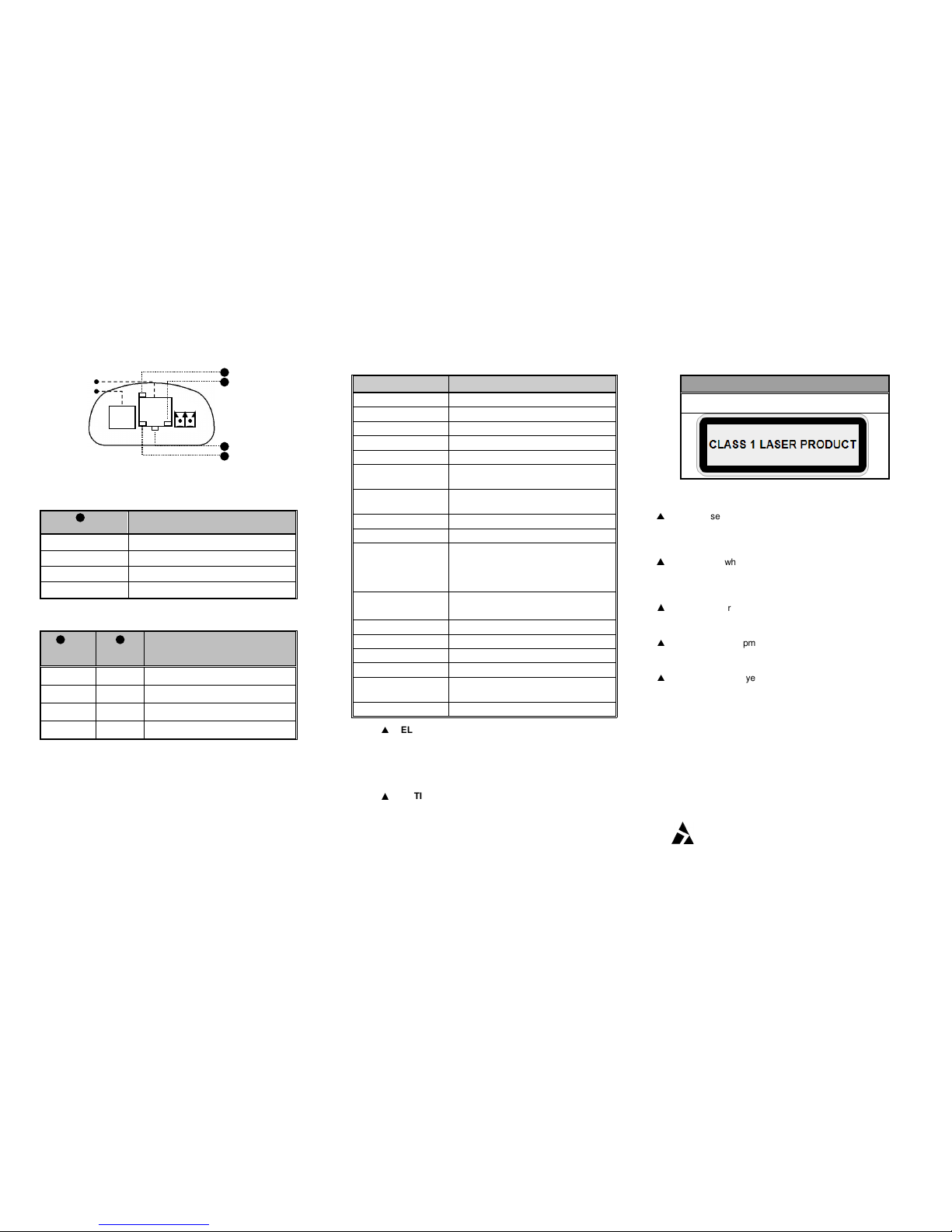
Port Allocation and LED indicators
Optical Port LED indicators
Fiber Link/Act
Function
Green Link OK
Blinking Link Activity
Red No optical signal received
- -
Copper Port LED indicators
Link/Act
100Mb/s
(Amber)
Function
- On 100Mb/s connection
- Off 10Mb/s connection
On - Copper Link OK
Blinking - Copper Link Activity
Technical Specifications
Specification Performance
Data Interface
IEEE 802.3 Ethernet
Data Rate 10/100Mbps
Operating Mode Half or Full Duplex
Data Connector
RJ45
Optical Interface
100Base-Fx
Optical Port
Connector
SFP - LC for 2-fiber, SC for 1 fiber
Transmitter Optical
Power
-15 to -8dBm into singlemode fiber
(see SFP datasheet for options)
Receiver Sensitivity
<-33dBm
Receiver Saturation >-3dB
Standard SM Optical
Link Budget
>18dB:
>10km on multimode fiber @
1310nm
>40km on singlemode fiber
@ 1310nm
Power Requirements
+8VDC to +35VDC
22VAC to 28VAC at 3VA
Power Connector 3.5mm 2-way terminal block
Enclosure Anodised elliptical metal case
Dimensions (mm) 52W x 55D x 26H
Weight of Module
300g
Operating
Temperature
-20 to 75°C
Relative Humidity 0 to 95% non-condensing
▲
ELECTROMAGNETIC COMPATIBILITY
WARNING: This is a Class A product. In a domestic
environment this product may cause radio interference
in which case the user may be required to take
adequate measures.
▲
OPTICAL OUTPUT OPERATION
WARNING: Laser Safety: Class 1 Laser Product per
IEC/EN 60825-1:20011 standard.
Class 1
The OSD2051 is a Class 1 laser product.
Precautions
▲
All service personnel should be provided training as
to the hazards of direct viewing of laser radiation and
of the precautionary measures during servicing of
equipment
▲
Areas where laser products are installed should be
restricted in access to trained service personnel only
and appropriate warning signs posted in the work
area.
▲
All laser apertures should be covered by protective
covers when not connected to optical fibers. Never
leave outputs uncovered.
▲
Laser equipment should be positioned above or
below eye level where possible. Apertures should be
positioned away from personnel
▲
Protective eyewear should be worn in the vicinity of
laser equipment
Warranty/Repairs
Thank you for purchasing equipment designed, manufactured and
serviced by Optical Systems Design (OSD). OSD warrants that at
the time of shipment, its products are free from defects in material
and workmanship and conforms to specifications.
For warranty period and repair service please contact your local
OSD distributor.
OPTICAL SYSTEMS DESIGN PTY LTD
7/1 Vuko Place, Warriewood 2102.
PO Box 891, Mona Vale,
NSW, Australia 1660.
Phone: +61 2 9913 8540
Fax: +61 2 9913 8735
1111
2222
3333
4444
Not Used
Link/Act
Fiber Link/Act
100Mbps
Ethernet Port
SFP Port
2222
4444
3333
 Loading...