

Page 1

SWG
INSTALLATION GUIDE
OPERATOR SPECIALTY COMPANY, INC.
UL325 COMPLIANCE REQUIRES THE USE OF CONTACT EDGES
OR PHOTOELECTRIC CONTROLS ON ALL AUTOMATIC OR
REMOTELY-CONTROLLED GATE OPERATORS.
®
CASNOVIA, MI 49318 • U.S.A.
Oct. 2005, Rev. 20
Page 2

SWG OPERATOR INSTALLATION GUIDE
TABLE OF CONTENTS
PRE-INST ALLATION INFORMA TION
Gate Operator Classifications ......................................................................................................................................3
Safety Information and Warnings .................................................................................................................................3
Pre-Installation Information ...........................................................................................................................................3
Warranty......................................................................................................................................................................3
INST ALLATION
Wiring Specifications ...................................................................................................................................................4
Post Mounting Instructions ..........................................................................................................................................5
String Method for Nonstandard Installation of Swing Gate Operators ............................................................................6
Articulating -Style Arm Assembly Instructions .............................................................................................................7
Vent Plug Installation ...................................................................................................................................................8
T orque Limiter Adjustment ...........................................................................................................................................8
Electrical Connection and Adjustments........................................................................................................................9
Limit Cam Adjustments ...............................................................................................................................................9
CONTROL BOARD ADJUSTMENTS and ACCESSORY CONNECTIONS
Control Board Adjustments ........................................................................................................................................10
T erminal Connection Descriptions .............................................................................................................................. 11
Current Sensing Adjustments ....................................................................................................................................12
Close Direction Current Sense Adjustment ................................................................................................................12
Open Direction Current Sense Adjustment.................................................................................................................12
Maximum Run Timer Adjustment ...............................................................................................................................12
Auto Close Timer Adjustment ....................................................................................................................................12
Master/Slave Connection ...........................................................................................................................................12
Onboard L.E.D. Indicator Descriptions ....................................................................................................................... 13
Important Notes for Installation of Master/Slave Applications......................................................................................14
Surge Protector Instructions ......................................................................................................................................14
Control and Accessory Connection Illustrations ....................................................................................................15-18
ILLUSTRA TIONS
Loop Layout Illustration ..............................................................................................................................................19
Edge Layout Illustration #1.........................................................................................................................................20
Photo Eye Illustration.................................................................................................................................................21
TROUBLESHOOTING ...................................................................................................................................................22
P ARTS LISTS
How to Order Replacement Parts...............................................................................................................................22
Model SWG Mechanical Parts Exploded View...........................................................................................................23
Model SWG Mechanical Parts List ............................................................................................................................24
Model SWG Single Phase Control Box Exploded View and Parts List .......................................................................25
Model SWG Three Phase Control Box Exploded View and Parts List ........................................................................26
Model SWG Gate Arm Assembly Parts List ..............................................................................................................27
PREVENT ATIVE MAINTENANCE ..................................................................................................................................29
GA TE OPERAT OR INSTALLA TION CHECKLIST ..........................................................................................................30
CAUTION!
DO NOT INST ALL
CONTROLS ON OR
NEAR THE GA TE
CAUTION!
ONL Y QUALIFIED SERVICE
TECHNICIANS SHOULD
WORK ON AN OSCO
SWING GA TE OPERAT OR
- 2 -
CAUTION!
DO NOT INST ALL
CONTROLS ON
THE OPERA TOR
Page 3

SWG OPERATOR INSTALLATION GUIDE
GATE OPERATOR
CLASSIFICATIONS
All gate operators can be divided into one of four different
classifications, depending on their design and usage.
Class I Residential Vehicular Gate Operator
A vehicular gate operator intended for use in a home of one to
four single family dwellings, or garage or parking area associated with these dwellings.
Class II Commercial / General Access Vehicular Gate
Operator
A vehicular gate operator intended for use in a commercial
location or building such as a multifamily housing unit of five
or more single family units, hotel, retail store or other building
servicing the general public.
Class III Industrial / Limited Access Vehicular Gate
Operator
A vehicular gate operator intended for use in an industrial
location or building such as a factory or loading dock area or
other location not intended to service the general public.
Class IV Restricted Access V ehicular Gate Operator
A vehicular gate operator intended for use in a guarded industrial location or building such as an airport security area or
other restricted access locations not servicing the general
public, in which unauthorized access is prevented via supervision by security personnel.
IMPORTANT!!
Before installing the gate operator , make sure the gate’s swing
is free and level throughout the entire swing path. If the gate
does not seem to operate properly , it may affect the operator
performance or greatly shorten the life of the unit. The gate
should be designed so that airflow is ample to prevent wind
resistance and drag.
SAFETY INFORMATION
AND WARNINGS
Read the following before beginning to install OSCO swing
gate operators:
1. Read the orange “Safety Instructions” brochure enclosed
with the packet of information. If you do not have one,
please call OSCO at 1-800-333-1717 to request one. Read
and follow all instructions.
2. All electrical connections to the power supply must be
made by a licensed electrician and must observe all
national and local electrical codes.
3. A separate power-disconnect switch should be located
near the operator so that primary power can be turned off
when necessary .
4. Install the enclosed warning signs on both sides of the
gate. Each sign must be plainly visible from the side of
the gate on which they are mounted.
5. Never reach between, through or around the fence to
operate the gate.
6. Y ou must inst all all required safety equipment.
PRE-INSTALLATION
INFORMATION
Before unpacking, inspect the carton for exterior damage. If
you find damage, advise the delivery carrier of a potential claim.
Inspect your package carefully. You can check your
accessory box parts with the enclosed packing slip for your
convenience. Claims for shortages will be honored for only 30
days from the date of shipment.
Before installing the operator, read this manual completely
to ensure all requirements for proper installation are present.
Verify that the volt age to be used matches the voltage of the
operator.
The following contact or non-contact obstruction
detection devices have been approved for use
with OSCO slide gate operators as part of a UL325
compliant installation:
Contact Edges:
Miller Models*: MG0-20, MGR-20, MGS-20, and ME-120
Photoeyes:
2520-441 MMTC Model IR-55 photoeye, 165’ with
mounting hardware
2520-031 MMTC Model E3K photoeye, 28’ with
mounting hardware
*for OSCO part numbers, contact a sales representative for details
- 3 -
10-05-20
Page 4

SWG OPERATOR INSTALLATION GUIDE
WIRING SPECIFICATIONS
1. Select from the chart at the bottom of this page corresponding to the
model, voltage and horsepower rating of your operator.
2. The distance shown on the chart is measured in feet from the operator to the power source. DO NOT EXCEED THE MAXIMUM DIS-
TANCE. These calculations have been based on standard 115V and
230V supplies with a 10% drop allowable. If your supply is under the
standard rating, the runs listed may be longer than what your application will handle, and you should not run wire too near the upper
end of the chart for the gauge of wire you are using.
3. When large-gauge wire is used, a separate junction box (not supplied) may be needed for the operator power connection.
4. All control devices are now 24VDC, which can be run considerable
distances. 24VAC is available for other devices, such as loop detectors and photo eyes.
5. Wire run calculations are based on the National Electrical Code, Article 430 and have been carefully determined based on motor inrush,
brake solenoids, and operator requirements.
USE COPPER WIRE ONLY!
6. Connect power in accordance with local codes. The green ground
wire must be properly connected.
7. Wire insulation must be suitable to the application.
8. Control wiring must be run in a separate conduit from power wiring.
Running them together may cause interference and faulty signals in
some accessories.
9. Electrical outlets are supplied in all 115VAC models for convenience
with occasional use or low power consumption devices only. If you
choose to run dedicated equipment from these devices, it will decrease the distance for maximum run and the charts will no longer be
accurate.
10. A three-wire shielded conductor cable is required to connect master
and slave operators. Y ou must use Belden 8760 T wisted Pair Shielded
Cable (or equivalent) only – OSCO part number 2500-1982, per
foot). See page 10 for details of this connection, as well as dip
switch selection. Note: The SHIELD wire should be connected
in both the master and slave operators.
MODEL SWG – SINGLE PHASE
gniriWrewoP
stloV
PH&
V511
2/1
PH
V511
4/3
PH
V511
PH1
222
453
665
009
0341
871
282
054
617
0411
061
452
604
646
6201
ecnatsiDxaM
111
771
382
054
517
98
1
14
522
853
075
08
721
302
323
315
eriW
lauDelgniS
eguaG
21
01
8
6
4
21
01
8
6
4
21
01
8
6
4
stloV
PH&
V802
2/1
PH
802
4/3
PH
V802
PH1
067
0021
4291
0603
4684
406
859
6251
4242
6583
445
468
4731
4812
6743
ecnatsiDxaM
083
006
269
0381
2342
203
874
367
2121
8291
272
234
686
2901
8371
eriW
lauDelgniS
21
01
8
6
4
21
01
8
6
4
1
2
01
8
6
4
stloV
eguaG
PH&
V032
2/1
PH
V032
4/3
PH
V032
PH1
iDxaM
ecnats
498
017
046
744
2241
117
4622
0063
4275
8211
6971
2582
8354
6101
6161
0752
0904
2311
0081
2682
553
465
8
89
6241
9622
023
805
808
5821
5402
eriW
lauDelgniS
eguaG
21
01
8
6
4
21
01
8
6
4
21
01
8
6
4
ACCESSORY WIRING
All Models
Volts
24VAC
24VDC
*Over 350 ft. use DC power.
Maximum
Distance (ft.)
250
350*
0-2000
Wire
Gauge
14
12
14
MODEL SWG – THREE PHASE
esahP3:gniriWrewoP
stloV
PH&
ecnatsiDxaM
eriW
lauDelgniS
stloV
eguaG
PH&
ecnatsiDxaM
eriW
lauDelgniS
eguaG
stloV
PH
&
ecnatsiDxaM
lauDelgniS
eriW
eguaG
V802
2/1
PH
V802
4/3
PH
V802
PH1
2411
175
6181
809
0982
029
417
064
4641
237
0332
753
6311
865
4081
209
21
01
5441
8
21
01
5611
8
21
01
8
V032
2/1
PH
V032
4/3
PH
V032
PH1
4431
276
7312
0043
4801
245
3271
2
68
1472
048
02
4
6331
866
4212
21
9601
01
0071
8
21
01
1731
8
21
01
2601
8
2/1
PH
4/3
PH
- 4 -
V064
V064
V064
PH1
1483
6016
2179
9723
2125
1928
9862
4724
8976
1291
3503
6584
6062
6414
7342
9933
21
01
8
0461
21
01
8
5431
21
01
8
12-02-11
Page 5

SWG OPERATOR INSTALLATION GUIDE
POST MOUNTING INSTRUCTIONS FOR MODEL SWG
NOTE: Maximum gate opening
angle is approximately 95 degrees,
depending on gate width. If larger
opening angle is required, nonstandard positioning of the operator and modified articulating arms
will be required. Contact the factory for pricing and availability.
DOOR MUST
FACE A WA Y
FROM
DRIVEWAY
Use two 3 - 3 1/2” diameter galvanized posts and secure with concrete
footings as shown, length to be determined by local codes, frost line
depth, and soil conditions.
Attach the operator with the U-bolts, side plates and hardware provided. There are four side plates. The 3/16” side plates go on the inside top of the operator, while the two 1/2” side plates go on the inside
bottom (see the illustration at right). The operator should be positioned
at a level to allow the arm to be installed at mid-height on the gate. “H”
dimension can vary depending on gate construction. Make sure the
posts do not protrude above the operator cabinet.
Assemble the arm components as shown on page 7.
A SEP ARA TE PEDESTRIAN GATE IS REQUIRED FOR
ALL PEDESTRIAN TRAFFIC. THIS GA TE MUST BE A
MINIMUM DIST ANCE OF 7 FEET FROM THE
VEHICULAR GATE AND GATE OPERA TOR
- 5 -
23” SPACE REQUIRED BEHIND OPERA T OR
FOR ARM CLEARANCE WHILE OPENING
IF NONSTANDARD MOUNTING IS NECESSAR Y ,
CONSULT THE F ACTOR Y
SIDE PLATE INST ALLA TION
3-05-19
Page 6

SWG OPERATOR INSTALLATION GUIDE
STRING METHOD FOR NONSTANDARD INSTALLATION OF SWING GATE OPERATORS
Step A: Position the Operator
1. Connect the gate plate assembly onto the gate at the recommended
location for a standard installation (Dimension “W”).
2. Open the gate to its fully-open position.
3. Position the operator parallel to the gate. The distance from the operator
output shaft to the gate plate pivot point is shown at right. The operator
should be positioned the same distance from the gate hinge as the gate
plate has been; ie: the “W” dimension.
Step B: Measure the Crank Extension and Link Center to Center
Distances
1. Close the gate.
2. Using a piece of tape, attach a string to the top of the operator output
shaft, at its center. Holding the string taut and using another piece of
tape, hold the other end of the string across the hole in the gate plate.
This distance is Dimension 1. Carefully measure this dimension and
write it down.
3. Open the gate.
4. Pick up the string, while it is still attached at both ends, and pull it taut
again while positioning it directly over the center of the operator shaft, at
Point “B,” and work your way back along the string until you reach Point
“C.”
5. While holding the string taut, measure the distance from Point “B” to
Point “C.” This is the required center to center distance for the crank
extension.
6. Measure the distance from Point “A” to Point “C.” This is the required
center to center distance for the link section.
7. When added together, the distances from Point “A” to Point “B” and
Point “B” to Point “C” should equal the Dimension 1 measurement.
DOOR MUST
FACE A WA Y
FROM
DRIVEWAY
These measurements will be needed when placing an order for special
length crank extensions and links. Also note that the measurements you
have just calculated are center to center only , and are not overall dimensions, which would also include other attachment hardware, such as gate
arm clamps.
It is also possible that both open and closed limit switches may be activated at either end of gate travel due to the total gate travel required, and
the shape of the limit switches and cams. This problem can be corrected
by carefully bending the limit switch arm slightly and readjusting its cam.
PLEASE NOTE: Y our operator may look different when installed.
The drawings on this page are for general reference only .
- 6 -
Page 7

SWG OPERATOR INSTALLATION GUIDE
ARTICULATING-STYLE ARM ASSEMBLY INSTRUCTIONS FOR MODEL SWG
Numbered items in these
drawings are for instructional
reference only . For actual part
numbers, go to the parts lists
in the back of this booklet.
Place the crank extension (2) on the operator crank
(1) as shown. Slide a black spacer (3) into the crank
and hold it while sliding a 1/2-13 x 1 3/4” hex head
bolt (4) through the extension and crank. Assemble
with a 1/2” flat washer and locknut and tighten. Slide
the clevis pin (5) and a 1/2” flat washer through the
crank and the extension. Slide another 1/2” flat
washer over the end of the pin and lock it with either
a disconnect pull pin or with an optional pad lock
through the pin.
Slide a 1/2” lockwasher and flatwasher onto the 1/2-13 x 2 1/
2” hex head bolt (10). Add a nylon washer (8), then slide the
bolt through the crank extension (2) and hold in place Next,
insert the yellow-plated pivot spacer (1 1) into the crank extension, add a nylon washer (8) and place the offset spacer
(7) on top of the nylon washer. Add a nylon washer (8) to the
top of the offset spacer (7) and add the silver zinc-finish
overtravel stop spacer (18). Slide the overtravel stop bracket
(9) over the silver zinc-finish spacer and add the last nylon
washer (8) above the bracket. Carefully screw the bolt assembly into the aluminum gate clamp (6) until the lockwasher
has been fully compressed. The overtravel stop and crank
extension should float freely , without binding, when it is fully
assembled. Tighten set screw (19) to further lock hex holt
(10) in place.
Angle iron (not supplied) (13) should be welded to the gate
prior to this step. Att ach the gate plate (12) to the angle iron
using 3/8 bolts, flat washers, lock washers and hex nuts
(15). Slide a 1/2-13 x 1 1/4” bolt, 1/2” lock washer, 1/2” flat
washer (14), and a black spacer (3) through the gate plate.
Place a nylon washer (8) over the opening in the gate plate.
Thread the bolt into the hole in the gate clamp (6) and tighten
carefully. Do not overtighten! Tighten set screw (19) to
further lock hex bolt (14) in place.
NOTE: Illustrations shown on this page are for right-hand application.
For left-hand, overtravel stop (9) should be on the opposite side from what is shown above.
Slide the pipe link (16) through the arm assembly as shown.
Place the 5/16” square bolts in the gate clamps (17) and
tighten carefully. Do not overtighten!
- 7 -
8-04-18
Page 8

SWG OPERATOR INSTALLATION GUIDE
VENT PLUG INSTALLATION
Gear reducers used in OSCO gate operators will have solid plugs installed prior to shipment in order to keep the oil inside from
spilling out during shipping. A vent plug has been provided to replace this plug during installation. This plug will look similar to the
ones shown below. Some models may have a vent plug with a breather pin. This pin should be removed after installing the
operator.
OR
TORQUE LIMITER ADJUSTMENT
Before adjusting the torque limiter, make sure the gate is in
good working condition. One person should be able to move
the gate by hand. Be certain the gate moves freely and without binding throughout its travel. Torque limiters are set light
at the factory . They must be adjusted during installation, preferably after limit cams have been manually set (see page 9).
Adjust the torque limiter tight enough to keep it from slipping
during normal operation.
To adjust the torque limiter in model SWG:
1. Bend the locking tabs away from the adjustment nut.
2. To increase the output , turn the adjustment nut clock-
wise one flat, or 1/6 turn, at a time until desired output is
obtained.
To reduce the output, turn the adjustment nut counterclockwise one flat, or 1/6 turn, at a time until desired
output is obtained.
3. Bend the locking tabs up to lock the adjustment nut in
place.
ADJUSTMENT NUT
LOCKING TAB
MODEL SWG
- 8 -
Page 9

SWG OPERATOR INSTALLATION GUIDE
ELECTRICAL CONNECTION AND ADJUSTMENTS
Power supply must be of correct voltage and phase.
Always disconnect power from operator before servicing.
Keep clear of gate during operation.
All OSCO gate operators are supplied with a power disconnect switch to turn on and off the power supply available to the
operator. Incoming power should be brought into the operator and connected to the labeled pigtails in the disconnect box,
following wiring specifications on page 4. A wiring connections print can be found on the inside cover of the operator .
Proper thermal protection is supplied with the operator. The motor contains a thermal overload protector to protect from overheating the motor due to overload or high-frequency operation. This overload will reset automatically after the motor cools down.
LIMIT CAM ADJUSTMENTS
The limit cams are not preset at the factory and must be adjusted for the length and opening angle of the gate the operator is
installed on. The limit switches are activated by a series of rotating limit cams which are attached to the drive shaft. The operator
has also been preset in the right hand operation mode. If the installation requires left hand operation a dip switch must be flipped
(see page 10).
With the gate connected to the gate operator in a mid-travel position, the power disconnect switch turned OFF, and the torque
limiter set loose enough to slip freely , manually move the gate to its fully open position.
Once the gate is in the fully open position, adjust the limit cam for open direction. Set the LSO-1 limit cam so that it has just
triggered its switch.
Once the open limit cam is set, repeat the above process for the close direction, LSC-1.
After finishing the initial limit cam adjustments, reposition the gate to approximately the center of travel. At this time, adjust the
torque limiter as explained on page 8. Turn the power disconnect switch ON, stand clear of any moving parts and press the
OPEN button. Observe the gate as it runs through a complete cycle in both directions, and adjust your limit s again if necessary .If
the operator stops during travel, you may need to adjust the open or close current sensor adjustment or the maximum run timer
(see page 12).
L2
(BLACK)
POWER DISCONNECT BOX
(115V AC VERSION SHOWN)
(WHITE)
GROUND
(GREEN)
L1
FROM TOP TO BOTTOM:
LEFT HAND RIGHT HAND
LSC-1 LSO-1
LSO-1 LSC-1
LIMITS and CAMS
MODEL SWG
WHENEVER HAND OF OPERATION CHANGES, BOTH LIMIT CAMS WILL
NEED TO BE ADJUSTED.
- 9 -
9-13-02
Page 10
LIMIT SWITCH
L.E.D.s
LIMIT SWITCH
CONNECTOR
TERMINAL STRIP #1
CONNECTOR
Control Board
with AC
Motor Board
SWG OPERATOR INSTALLATION GUIDE
CONTROL BOARD ADJUSTMENTS
TERMINAL STRIP #2
CONNECTOR
NOTE: DO NOT FORCE 270-DEGREE POTENTIOMETERS
BEYOND THEIR NORMAL RANGE OF MOTION
OR DAMAGE MA Y RESULT!
DIAGNOSTIC
L.E.D.s
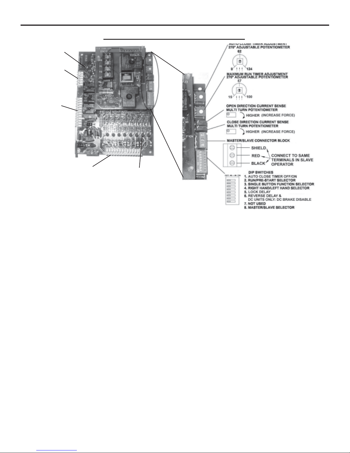
Auto Close Timer Adjustment: This 270-degree adjustable potentiometer will signal the operator to close automatically,
provided no open, reversing or obstruction signals are present from the fully-open position. This timer is adjustable from 0 to 124
seconds. This feature is turned on or off using dip switch #1.
Maximum Run Timer Adjustment: This 270-degree adjustable potentiometer will signal the operator to stop running once it
counts down, unless a limit switch is reached or an input is received first. Each time the motor starts, this timer will begin
counting. This timer is adjustable from 15 to 100 seconds. If the timer expires, the unit locks out and the emergency alarm
sounds.
Open Direction Current Sense Adjustment: This multiturn potentiometer is used to calibrate the built-in current sensing
feature for detection of obstructions while running in the open direction.
Close Direction Current Sense Adjustment: This multiturn potentiometer is used to calibrate the built in current sensing
feature for detection of obstructions while running in the closed direction.
Master/Slave Connection Block: This terminal block is used in conjunction with two operators to configure two gates to open
and close together.
Dip Switches:
# 1 This switch turns the auto close timer off/on.
# 2 This switch is used in conjunction with alarms and flashing lights that may be added to the operator. When the switch is
in the ON position, these devices will start approximately two seconds prior to the operator starting. In the OFF position,
the devices will only work while the operator is running.
# 3 This switch is used in conjunction with single-button controls and radio receivers. In the ON position, successive inputs
will cause signals in the order of OPEN-STOP-CLOSE-STOP. In the OFF position, inputs will cause an OPEN signal
unless the gate is fully open, in which case it will signal CLOSE.
#4 This switch determines right-hand vs. left-hand behavior . When looking from inside the protected area toward the gate, the
side of the drive the operator is on determines its hand of operation. In the OFF position, the operator is set for right-hand.
# 5 When turned ON, this switch will allow a one-second delay for solenoid locks to unlock before the motor starts.
# 6 In the ON position, the reverse delay is 1 1/2 seconds. In the OFF position, the reverse delay is 3 seconds.
# 7 Not used at this time.
# 8 This switch is used to set Master/Slave configuration. Operators which are stand-alone or master units should be set to
OFF, while only slave units should have this switch set to ON.
- 10 -
3-05-19
Page 11

SWG OPERATOR INSTALLATION GUIDE
TERMINAL CONNECTION DESCRIPTIONS
TERMINALS FUNCTION DESCRIPTION OF FUNCTION
24V A C 24V A C Provides fused 24Volt AC power for accessories.
24V AC N Note: DC models will NOT have 24Volt AC power available.
24VDC+ 24VDC Provides fused 24Volt DC power for accessories.
24VDC- COMM.
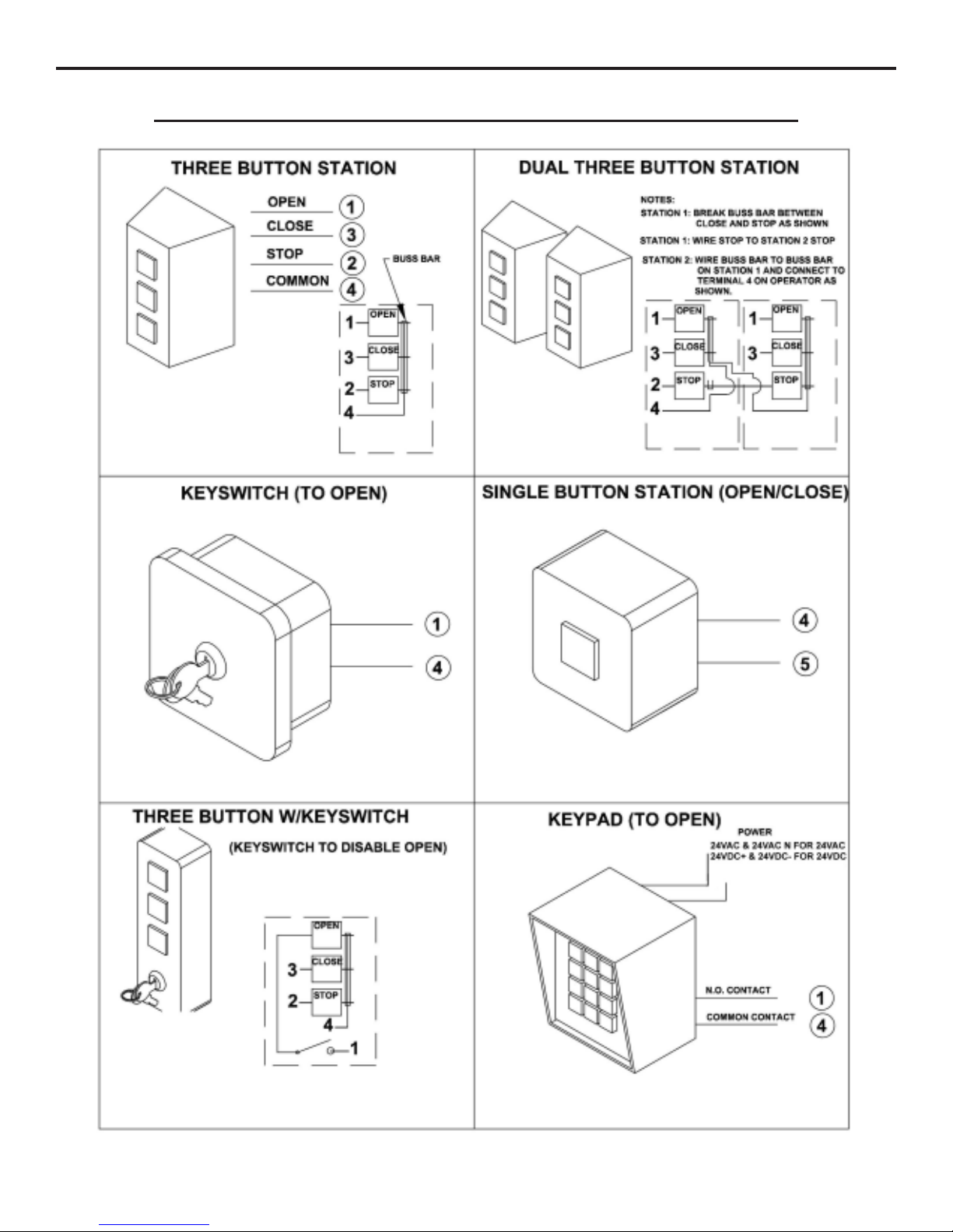
1 & 4 OPEN Opens the operator. Several accessories such as button stations, keypads, trans-
mitters and card readers can be wired to open.
3 & 4 CLOSE Closes the operator. Use caution when wiring accessories to these terminals.
The gate must be clearly visible from the location of any accessories wired
to close.
4 & 5 SINGLE-BUTTON Performs the single-button function which will alternate between open and close
or open, stop and close - depending on dip switch #3. (See page 10 for details.)
2 & 4 STOP Stops the operator. If no stop button is used, a jumper is required across 2&4.
4 & 6 REVERSE This function will cause a reversal when the gate is traveling closed and will travel
back to the fully open position. Loop detectors are often wired for reverse.
4 & 50 OPEN This function works only while the operator is opening. Any signal to this function
OBSTRUCTION
4 & 51 CLOSE This function works exactly like the OPEN OBSTRUCTION, except that it will only
OBSTRUCTION
4 & 11 SHADOW/HOLD This function will keep the gate in its fully open position while the signal is present.
24VDC+ & 60 RUN/PRE-STAR T A 24Volt DC device such as a strobe light or alarm can be wired to these terminals.
You must follow all required safety precautions and instructions at all times. Review the safety brochure
included with the operator. If any pages are missing or unreadable, contact OSCO at 1-800-333-1717 to request
additional copies.
will cause the gate to stop, reverse a short distance, and then stop again. At this
time the auto close timer is disabled, and a renewed input will be required to start
the gate again. Should the gate be restarted and the signal occur again prior to
reaching a limit, the gate will stop again, and this time will sound the emergency
alarm and lock out.
work in the closing direction.
This is typically used with a loop and loop detector to keep a large swing gate
open while vehicular traffic is passing through.
Depending on dip switch #2, these devices will either begin three seconds before
the operator starts, or only while the motor is running. (See page 10 for details.)
Never connect a button station within reach of the gate or on the side of the gate operator.
Do not adjust the circuit board current sensing feature too high. It should be adjusted high enough to keep the
gate from falsely triggering the sensing, but no higher than necessary for the gate to operate. Do not defeat the
purpose of this function!
- 11 -
3-05-19
Page 12

SWG OPERATOR INSTALLATION GUIDE
CURRENT SENSING ADJUSTMENTS
Because gates vary in construction and may have different force requirements in the open and close directions to move, the
OSCO control board has separate Multi-turn potentiometers for adjusting in both directions independently. The adjustment
should be set light enough to maintain minimal force (40 lbs.) should an obstruction occur, but high enough to keep the gate
moving under normal conditions without interruption.
Prior to adjusting the operator current sensing functions, make sure the gate moves freely in both directions. A badly aligned or
poorly maintained gate may cause false triggering of the current sensor . Refer to page 10 when following the instructions below.
A factory adjustment tool has been supplied to make these adjustment s easier. This tool has been taped to the control box for
your convenience.
CLOSE DIRECTION CURRENT SENSE ADJUSTMENT
When the gate operator leaves the factory, it has been preset for a relatively light gate function and will require additional
adjustment. Begin by starting the gate going closed. If the operator stops and reverses, turn the close direction potentiometer
(see page 10) one turn higher, press the STOP button, and try again. Repeat this process until the gate no longer causes false
tripping of the current sensor. Note that each time the gate operator reverses, the STOP button must be pressed. Next, turn the
close direction potentiometer lower slowly while the operator is running the gate closed until the gate operator stops and
reverses again. From this point, turn the close direction potentiometer higher by 1 1/2 turns for all 1 15 Volt AC and 24 Volt DC
operators, and by 3/4 of a turn higher for all 230 Volt AC operators. Additional fine adjustment by 1/4 turns may be necessary to
eliminate false triggering.
OPEN DIRECTION CURRENT SENSE ADJUSTMENT
Repeat the same process with the open direction potentiometer while running the gate in the open direction. Once this is done,
run the gate through several complete cycles and make sure the gate does not false trip in either direction.
Multi-turn Potentiometer
Remember it is important not to set the adjustment
too high! Doing so will defeat the purpose of the current sensing as an obstruction detecting feature.
MAXIMUM RUN TIMER ADJUSTMENT
This adjustable potentiometer sets the maximum length of time the motor will run before shutting down. It should be configured
for the time it takes to run the gate fully open or closed, plus an additional 15 seconds. See page 10 for details.
AUTO CLOSE TIMER ADJUSTMENT
This adjustable potentiometer sets the length of time which elapses before the gate operator automatically closes the gate, from
the fully open position, provided no open, reversing, or obstruction signals are present. This feature can be turned on or off via dip
switch selection. See page 10 for details. Do not use the auto close timer without an appropriate reversing device
installed!
MASTER/SLAVE CONNECTION
A three-wire shielded conductor cable is required to connect master and slave operators. Y ou must use Belden 8760 T wisted
Pair Shielded Cable (or equivalent) only – OSCO part number 2500-1982, per foot). See page 10 for details of this connection,
as well as dip switch selection. Note: The SHIELD wire should be connected in both the master and slave operators. In addition, you
must run power to both the master and slave operators.
- 12 -
3-05-19
Page 13

SWG OPERATOR INSTALLATION GUIDE
ONBOARD L.E.D. INDICATOR DESCRIPTIONS
Control Board L.E.D. Indicators:
OPEN This indicator is lit when an open signal is present. This signal can come from such devices as button
stations, radio receivers, keypads and telephone entry systems.
CLOSE This indicator is lit when a closed signal is present. This signal typically comes from three-button stations.
STOP This indicator is lit when there is a break in the stop circuit. Make sure there is a stop button wired in and
working properly .
SINGLE This indicator is lit when a signal from a single-button station or radio receiver is present.
CLOSE OBST This indicator is lit when a close obstruction signal is present. This signal can come from edges and photo
eyes which have been wired to the close obstruction inputs.
OPEN OBST This indicator is lit when an open obstruction signal is present. This signal can come from edges and
photo eyes which have been wired to the open obstruction inputs.
SAFETY LOOP This indicator is lit when a reversing signal is present. This signal is generated by a loop detector wired to
the safety loop terminals.
SHADOW LOOP This indicator is lit when a shadow/hold open signal is present. This signal is generated by a loop detector
LH
LSC-1
LSC-2
LSO-1
LSO-2
Motor Board L.E.D. Indicators:
NON LABELED One of these two indicators will be lit when the motor is running the gate open, and the other is lit when the
BRAKE REL. This indicator is lit when the brake is NOT applied.
RH
LSO-1
LSO-2
LSC-1
LSC-2
wired to the shadow loop terminals.
This indicator is lit when the open #1 limit switch is activated on a right-hand operator, or the close #1 switch
on a left-hand. If this indicator is lit and the gate is not in its full open/closed position, the limit may need
adjusting or the limit switch may need replacing.
This indicator is lit when the open #2 limit switch is activated on a right-hand operator, or the close #2 switch
on a left-hand.
This indicator is lit when the close #1 limit switch is activated on a right-hand operator, or the open #1 on a
left-hand. If this indicator is lit and the gate is not in its full open/closed position, the limit may need
adjusting or the limit switch may need replacing.
This indicator is lit when the close #2 limit switch is activated on a right-hand operator, or the open #2 switch
on a left-hand.
motor is running the gate closed.
- 13 -
Page 14
SWG OPERATOR INSTALLATION GUIDE
IMPORTANT NOTES FOR
INSTALLATION OF MASTER/SLAVE APPLICATIONS
When setting up Master/Slave gate operators, it is best to make adjustments and run each operator individually. To do this,
simply:
a. Set Dip Switch #4 to proper hand of operation (right-hand or left-hand)
b. Set Dip Switch #8 as Master (off)
Run each operator making current sensing adjustments as necessary , as indicated on the Control Board Adjustments page of
this installation guide. When both operators have been adjusted, turn power off, then turn on Dip Switch #8 in the operator
chosen as the Slave.
The timer to close and radio/single button behavior are set in the Master operator.
The following selections are set individually:
Current Sensing
Maximum Run Timer
One-Second Lock Release
Three-Second Pre-Start Warning
Right/Left-Hand Selections
SURGE PROTECTOR INSTRUCTIONS
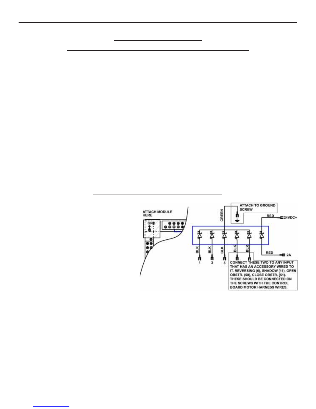
The optional surge protector should be connected
to any inputs that have an accessory connected to
it. This includes the 3-button station, so it must be
connected to 1, 2A and 3 in all cases. The green
wire connected to ground, which is electrically the
same as terminal 4. The red wires connect to
terminals 2A and 24VDC+. This will cause the
2 amp fuse to blow if this section of the module
becomes shorted. With any of the other inputs
connected to the surge protector, if their protection
line becomes shorted due to a surge over the rating
of the module, the corresponding LED on the main
board will remain lit, causing a constant signal to
the controller. If this is found, please replace the
entire surge protector with a new unit.
Do not simply unhook the shorted wire, as this
removes the protection from the circuit that was
saved by the protector in the first place!
- 14 -
8-03-14
Page 15
SWG OPERATOR INSTALLATION GUIDE
CONTROL and ACCESSORY CONNECTION ILLUSTRATIONS
- 15 -
Page 16

SWG OPERATOR INSTALLATION GUIDE
CONTROL and ACCESSORY CONNECTION ILLUSTRATIONS
- 16 -
Page 17

SWG OPERATOR INSTALLATION GUIDE
OSCO CONTROL and ACCESSORY CONNECTION ILLUSTRATIONS
- 17 -
Page 18
SWG OPERATOR INSTALLATION GUIDE
CONTROL and ACCESSORY CONNECTION ILLUSTRATIONS
24V
24V
- 18 -
Page 19
SWG OPERATOR INSTALLATION GUIDE
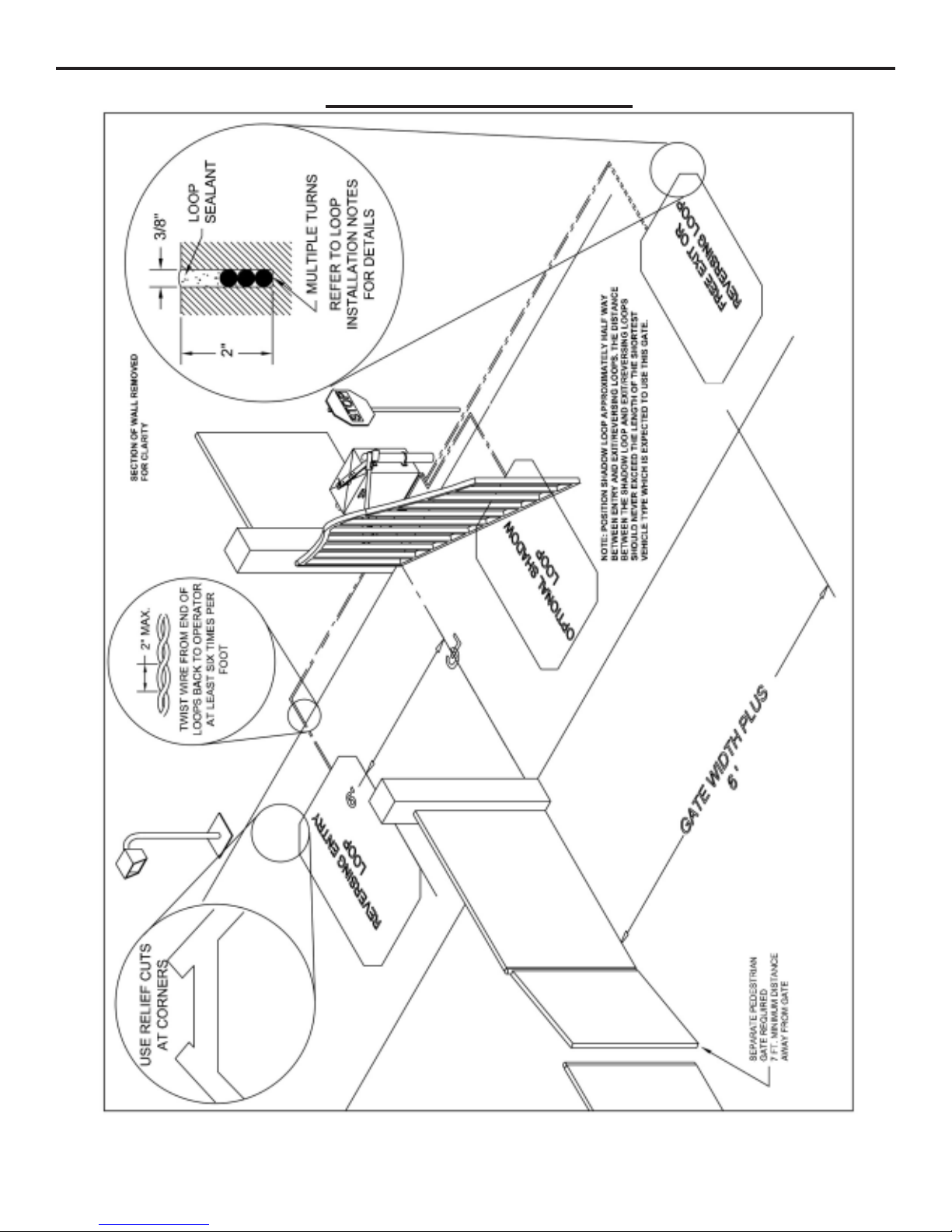
LOOP LAYOUT ILLUSTRATION
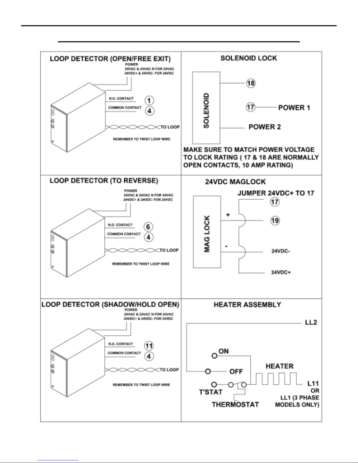
Refer to Connection Descriptions on page 1 1 and Loop Accessory Connections on page 18 for additional details.
- 19 -
Page 20
SWG OPERATOR INSTALLATION GUIDE
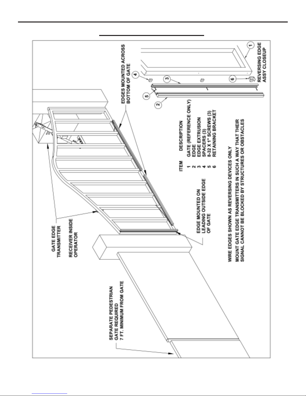
EDGE LAYOUT ILLUSTRATION
Refer to Connection Descriptions on page 1 1 and Contact Edge Connections on page 17 for additional details.
- 20 -
Page 21
SWG OPERATOR INSTALLATION GUIDE
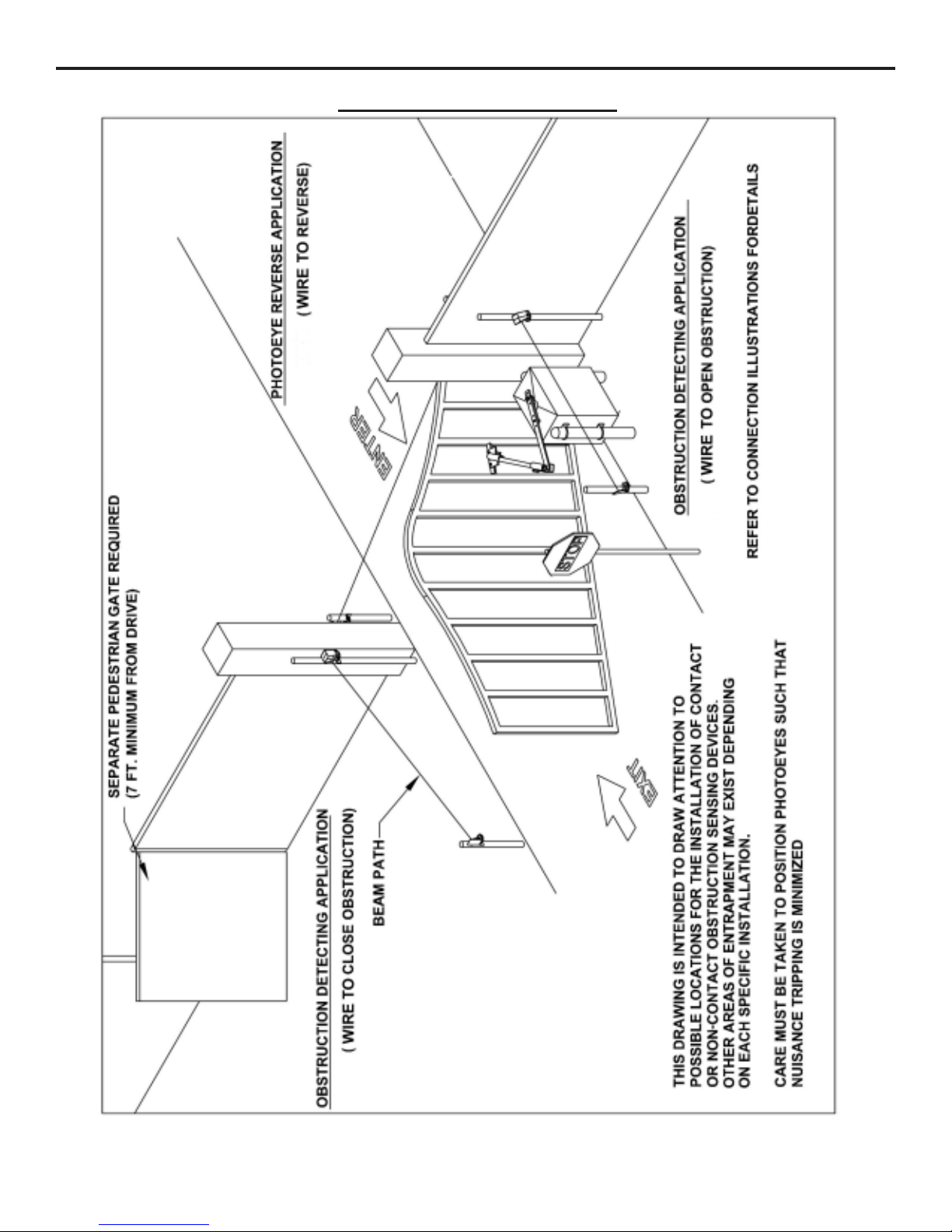
PHOTOEYE ILLUSTRATION
Refer to Connection Descriptions on page 1 1 and Contact Edge Connections on page 17 for additional details.
- 21 -
Page 22

SWG OPERATOR INSTALLATION GUIDE
TROUBLESHOOTING
Operator fails to start:
A. If the operator has been running a large number of cycles,
the motor may have gotten hot and tripped the overload.
Allow the motor to cool down and the overload will reset
automatically.
B. Make sure you have power at the master distribution panel
and that the power has not been turned off.
C. The secondary fuse on the control board may have blown.
Replace the fuse (refer to control box parts list on pages
25 [single phase] or 26 [three phase] for part number infor-
mation).
Motor operates, but gate does not move:
A. In operators with torque limiters and friction pad clutches,
check for signs of slipping. Y ou can mark the sprocket and
clutch with a yellow or white grease pen and watch for the
lines to move apart if slipping is taking place. Adjust the
torque limiter tighter if this is the problem.
B. Check for broken chain or worn belts.
C. Check all setscrews on pulleys and sprockets and tighten
them if necessary, and check for keys which may have
fallen loose from keyways.
Motor sounds like it is working harder than normal:
A. Make sure the gate is moving freely and without binding
throughout its entire travel.
B. Check the drive chain for obstructions (if the operator has
one).
C. If the operator has an internal brake mechanism, make
sure it is releasing.
Limit switch getting out of time:
A. Check for proper tension on all limit chains to be sure there
is no jumping taking place. Mark one tooth and its corre-
sponding link and run the gate. If the marks have moved,
the chain is skipping.
B. Check the setscrews in limit cams and limit sprockets for
tightness. In rotary limit boxes, check the rotary limit nut
for sloppiness or stripped threads. Replace if necessary .
Gate stopping part way open or closed
(but no visible obstruction):
A. The control board may have received a false obstruction
input triggered by current sensing set too low. Make sure
the gate moves freely through its entire travel before adjusting the current sensing.
B. The maximum run timer may have counted down and ex-
pired. This can be caused by having the timer set too low ,
if a chain or belt is broken, or if a sprocket or pulley is
slipping. When the timer expires, the gate stops and an
alarm will sound.
C. An obstruction signal from an accessory wired to the ob-
struction input may have triggered falsely . Check the control board for lit L.E.D. indicators for any of the following
inputs: safety, shadow, open obstruction, close obstruction, stop, etc. If any are lit when the operator should be
running, remove all devices hooked to that function and
hook them up one at a time and try to run the operator until
the problem device is found. Refer to page 13 for details on
the control board indicators.
Gate staying open with automatic system:
A. If there are vehicle detectors in your machine which are set
up for reverse, one of your loops or loop detectors may be
sending a false signal. Disconnect the wire harness and
try running the operator.
B. An opening or reversing device may be stuck or malfunc-
tioning. Try disconnecting these devices and hook them
back up one at a time and try running the operator until the
malfunctioning device is found.
C. Make sure the close limit switch isn’t activated. If it is, the
operator will think the gate is already closed.
HOW TO ORDER REPLACEMENT PARTS
Use the part numbers listed on the following pages. Contact your local OSCO dealer or distributor to order parts.
1. Supply the model number and serial number of your operator .
2. Specify the quantity of pieces needed and order by part number and name of part.
3. State whether to ship by freight, truck, parcel post, UPS or air express.
4. State whether transportation charges are to be prepaid or collect.
5. Specify name and address of person or company to whom parts are to be shipped.
6. Specify name and address of person or company to whom invoice is to be sent.
- 22 -
Page 23

SWG OPERATOR INSTALLATION GUIDE
MODEL SWG MECHANICAL PARTS EXPLODED VIEW
- 23 -
Page 24

SWG OPERATOR INSTALLATION GUIDE
MODEL SWG
MECHANICAL PARTS LIST
REF .
NO. PART NO. DESCRIPTION
2120-361-BT Complete Enclosure Assembly
with Door
1 2110-067-BT Enclosure Assembly without Door
2120-362-BT Enclosure Door and Lock Assembly
2300-716 Stop/Reset Button Cover
2 2110-164 Mounting Plate
4 2110-163 Bearing Spacer & Bracket Assembly, 3”
14 2110-173 Bearing Spacer & Bracket Assembly, 2”
15 2100-1034 Bearing Spacer, 2”
17 2100-708 Main Frame Mounting Bracket
25 2100-1414 Reducer Spacer Plate
3 2110-566 Output Shaft Welded Assembly:
1 1/8” bore with 40-B-48 Sprocket
2100-1913-BT Crank
27 2200-016 Moisture Seal
26 2100-1344 Moisture Seal Spacer
19 2200-224 Set Collar, 1 1/8” ID
5 2200-264 Pillow Block Bearing, 1 1/8”
6 2110-144 Limit Cam
16 2110-130 Intermediate Shaft Assembly
2100-688 Intermediate Shaft
2200-279 Sprocket, 40-B-9, 3/4” bore
13 2200-222 Pillow Block Bearing, 3/4”
7 2200-584 Torque Limiter
12 2200-281 Sprocket, 40-A-36
35 2400-520 E-Ring, 3/4”
11 2200-097 Gear Reducer, 60:1
9 2200-084 Sprocket, 40-B-13, 1” bore
2100-206 #40 Chain, 30 Links
2200-467 #40 Chain, 22 1/2”
2200-006 #40 Master Link
2400-254 Key, 3/16” x 3/16” x 3”
2400-201 Key, 1/4” x 1/4” x 1 1/2”
REF .
NO. PART NO. DESCRIPTION
28 2500-764 Limit Switch
29 2100-586 Limit Bracket
30 2510-248 Stop/Reset Button and Bracket
Assembly
2100-1760 Stop/Reset Button Mounting Bracket
2500-1495 Stop/Reset Button
31 2100-1782 Mounting Plate (single phase only)
32 2100-1683 Left Mounting Bracket
33 2100-1773 Right Mounting Bracket with Shelf
34 2510-251-D Power On/Off Disconnect Assembly
with Receptacles (115V Models only)
2500-1956 115VAC Duplex Receptacles only
2500-1957 115VAC Switch only
2510-252-D Power On/Off Disconnect Assembly
for 230V Models
2500-2205 230VAC Switch only
2500-294 Power On/Off Disconnect Assembly
for 3 Phase Operators
2500-034 Power Switch only
C-Face Motors
10 2500-2307 1/2 HP, 115V, 1 Phase
2500-2308 1/2 HP, 208/230V, 1 Phase
2500-2309 3/4 HP, 115V, 1 Phase
2500-2310 3/4 HP, 208/230V, 1 Phase
2500-2311 1 HP, 115V, 1 Phase
2500-2312 1 HP, 208/230V, 1 Phase
2500-2313 1/2 HP, 208/230/460V, 3 Phase
2500-2314 3/4 HP, 208/230/460V, 3 Phase
2500-2315 1 HP, 208/230/460V, 3 Phase
Capacitors
2500-2336 Capacitor for 2500-2307 Motor
2500-2337 Capacitor for 2500-2308 Motor
2500-1926 Capacitor #1 for 2500-2309 Motor
2500-1930 Capacitor #2 for 2500-2309 Motor
2500-1931 Capacitor for 2500-2310 Motor
2500-2338 Capacitor for 2500-2311 Motor
2500-1932 Capacitor for 2500-2312 Motor
- 24 -
3-05-19
Page 25
SWG OPERATOR INSTALLATION GUIDE
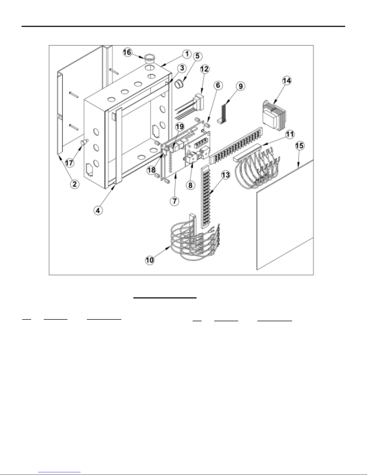
MODEL SWG SINGLE PHASE CONTROL BOX PARTS LIST
REF
NO. PART NO. DESCRIPTION
1 2100-1778 Control Box Wrapper
2 2100-1757 Control Box Mounting Plate
3 2100-1762 Terminal Strip Bracket, Output Side
4 2100-1761 Terminal Strip Bracket, Input Side
5 2200-122 Heyco Bushing, .87 diameter
6 2500-1948 Control Board Standoff
7 2510-268 Control Board
8 2500-1946 AC Mot o r D r i v e B o a rd
2510-244 Control Board with AC Motor Board
9 2510-254 Limit Switch Harness Assembly
10 2510-249 Input Wire Harness Assembly
11 2510-250 Output Wire Harness Assembly
12 2510-261 Control Box Motor Harness Assembly
13 2500-071 Terminal Strip, 16-141
14 2500-212 Transformer, 115/24VAC, 40VA
2500-791 Transformer, 230/24V AC, 40VA
REF
NO. PART NO. DESCRIPTION
15 2300 -6 9 6 Clear Control Box Cover
16 2300 -735 Heyco Bushing, 1.09 diameter
17 2200- 876 Plunger, Spring Loaded
250 0 - 8 67 Alarm, 24VAC (not shown)
18 2500-1966 2 Amp Fuse for Control Board
19 2500-1975 3 Amp Fuse for Control Board
2520-391-D Complete Controller Assembly
115VAC (order limit harness and
mounting brackets separately)
2520-392-D Complete Controller Assembly
230VAC (order limit harness and
mounting brackets separately)
- 25 -
4-02-9
Page 26
SWG OPERATOR INSTALLATION GUIDE
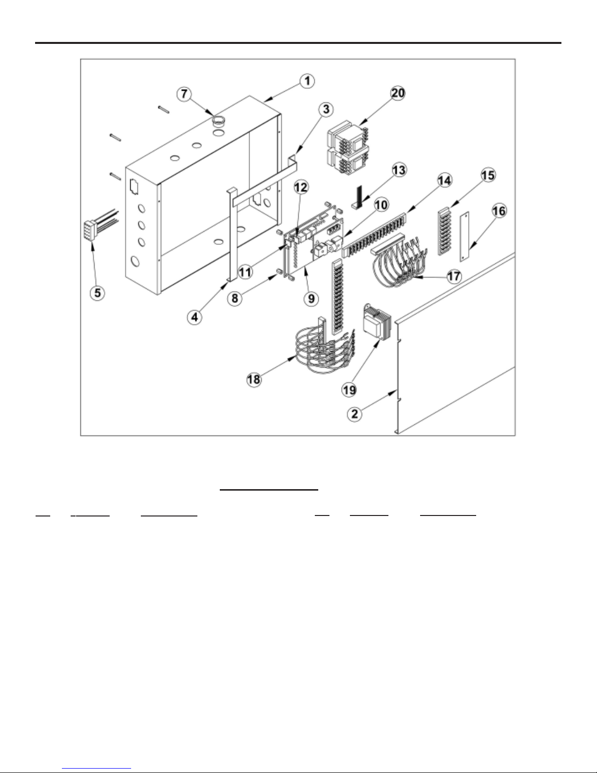
MODEL SWG THREE PHASE CONTROL BOX PARTS LIST
REF
NO. PART NO. DESCRIPTION
1 2100-1865 Control Box Wrapper
2 2100-1866 Control Box Cover
3 2100-1864 Terminal Strip Bracket
4 2100-1762 Terminal Strip Bracket
5 2510-293 Control Box Motor Harness Assembly
(Leeson motors)
2510-355 Control Box Motor Harness Assembly
(AO Smith motors)
7 2300-735 Heyco Bushing, 1.09 diameter
8 2500-1948 Control Board Standoff
9 2510-295 Control Board with 3 Phase Motor Board
2510-268 Control Board only
10 2500-1980 3 Phase Motor Board
11 2500-1966 2 Amp Fuse for Control Board
12 2500-1975 3 Amp Fuse for Control Board
13 2510-254 Limit Switch Harness
REF
NO. PART NO. DESCRIPTION
14 2500- 071 Terminal Strip, 16-141
15 2500 -27 0 Terminal Strip, 9-142 OR
2500 -185 Terminal Strip, 13-142
16 2300- 48 8 Terminal Strip Barrier for 9-142 OR
230 0-88 5 Terminal Strip Barrier for 13-142
17 2510- 250 Output Wire Harness Assembly
18 2510- 249 Input Wire Harness Assembly
19 2500-767 230/24VAC, 75VA, Transformer
2500-768 460/24VAC, 75VA, Transformer
20 2500-2084 24VAC Contactor
252 0-40 0 Controller, 208/230, 3 Phase
252 0-40 1 Controller, 460, 3 Phase
(order limit harness and mounting
hardware separately)
- 26 -
6-03-13
Page 27
SWG OPERATOR INSTALLATION GUIDE
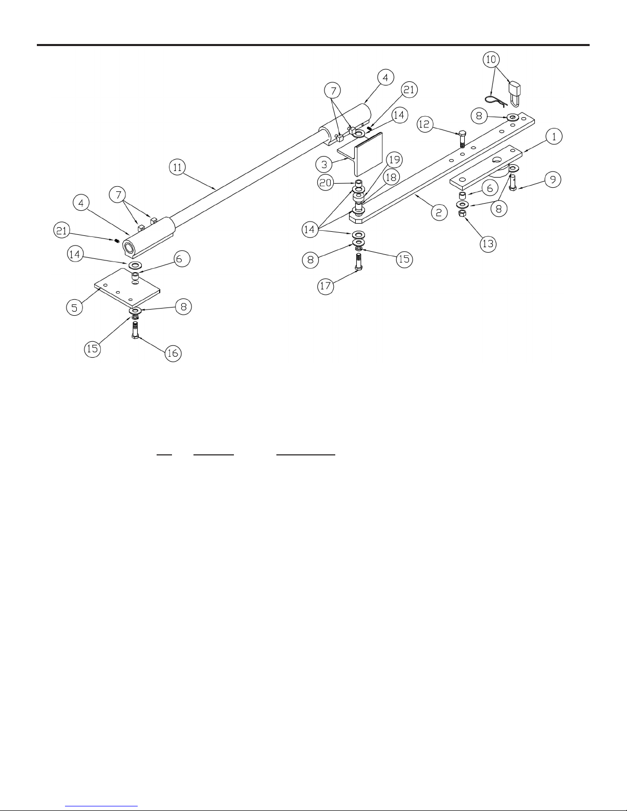
NOTE: CRANK SHOWN FOR
REFERENCE ONL Y
MODEL SWG GATE ARM ASSEMBLY PARTS LIST
REF
NO. PART NO. DESCRIPTION
2120-449-BT Complete Arm Assembly
1 2100-1913-BT Crank (not included in arm assembly)
2 2100-1722-BT Crank Extension
3 2100-1924-BT Overtravel Stop
4 2100-1597 Gate Arm Clamp
5 2100-1733-BT Gate Plate
6 2200-783 Spacer - black, 1/2” ID x 3/4” OD x 9/16” L TB
7 2400-378 Set Bolt, 5/16”-18 x 3/4”
8 2400-376 Flat Washer
9 2100-1547 Disconnect Pin
10 2400-351 Disconnect Hair Pin
2200-034 Disconnect Lock (optional)
11 2100-122-BT Pipe Link, 1”
12 2400-380 HHCS, 1/2”-13 x 1 3/4”
13 2400-418 Nylon Lock Nut, 1/2”
14 2300-238 Nylon Washer, 3/4” ID
15 2400-433 Split Lock Washer, 1/2”
16 2400-434 HHCS, 1/2-13 x 1 1/4”
17 2400-482 HHCS, 1/2-13 x 2 1/2”
18 2100-1725 Spacer - yellow, 3/4” OD x 1/2” ID x 3/4” LTB
19 2100-1932-BC Spacer - black, 1 1/4” OD x 1/2” ID x 1/2” LTB
20 2100-1320 Sp a cer - zinc-silver, 3/4” OD x 1/2” ID x 1/2” LTB
21 2400-309 Set Screw, 1/4” - 20 x 1
- 27 - 08-04-18
Page 28

sso
3
Date Prepared: February 02, 1996
Supersedes: January 07, 1995
MSDS Number: 225570
Cette fiche signaletique ast aussi disponible en francais
1. PRODUCT INFORMATION
Product Identifier: ESSO GEAR OIL GX 80W-90
Application and Use: Premium quality multigrade extreme pressure gear oil for use in
automotive applications including some manual transmissions.
Product Description: A lubricating oil consisting of a saturated and unsaturated hydrocarbons derived from paraffinic distillate, and additives.
REGULATORY CLASSIFICATION
WHMIS: Not a controlled product
CEPA: CANADIAN ENVIRONMENTAL PROTECTION ACT
All components of this product are either on the Domestic Substances List (DSL) or
are exempt.
TRANSPORT A TION OF DANGEROUS GOODS INFORMATION
Shipping Name: Petroleum Lubricating Oil
Class: Not regula te d Packing Group: Not regulated
PIN Number: Not regulated Guide Number: 129
Please be aware that other regulations may apply.
TELEPHONE NUMBERS MANUFACTURER/SUPPLIER
Emergency 24 hr. 519-339-2145 IMPERIAL OIL
Technical Info. 800-268-3183 Products Division
2. REGULATED COMPONENTS
The following components are defined in accordance with subparagraph 13(a) (l) to
(lv) or paragraph 14(a) of the Hazardous Products Act:
Not applicable
3. TYPICAL PHYSICAL & CHEMICAL PROPERTIES
Physical State: Liquid
Specific gravity: not available
Viscosity: 15.50 cSt at 100 deg. C
Vapour Density: not available
Boiling point: 229 to 600 deg. C
Evaporation rate: <0.1 (1=n-butylacefate)
Solubility in water: negligible
Freezing/Pour Point: -27 deg. C D97
Odour Threshold: not available
Vapour Pressure: <0.1 kPa at 20 deg. C
Density: 0.89 g/cc at 15 deg. C
Appearance/odour: Dark brown liquid, petroleum hydrocarbon odour.
4. HEALTH HAZARD INFORMA TION
NATURE OF HAZARD:
INHALATION: Negligible hazard at normal temperatures (up to 38 deg. C). Elevated
temperatures or mechanical action may form vapours, mists or fumes which may be
irritating to the eyes, nose, throat and lungs. Avoid breathing vapours or mists.
EYE CONTACT: Slightly irritating, but will not injure eye tissue.
SKIN CONTACT: Low toxicity. Frequent or prolonged contact may irritate the skin.
INGESTION: Low toxicity.
ACUTE TOXICITY DATA: Based on animal testing data from similar materials and
products, the acute toxicity of this product is expected to be:
Oral: LD50 > 5000 mg/kg (rat)
Dermal: LD50 > 3160 mg/kg (rabbit)
Inhalation: LC50 > 5000 mg/m3 (rat)
OCCUPA TIONAL EXPOSURE LIMIT :
ACGIH recommends: For oil mists, 5 mg/m3. Local regulated limits may vary.
5. FIRST AID MEASURES
INHALATION: Vapour pressure of this material is low and as such inhalation under
normal conditions is usually not a problem. If overexposed to oil mist, remove from
further exposure. Administer artificial respiration if breathing has stopped. Keep at
rest. Call for prompt medical attention.
EYE CONTACT: Flush eyes with large amounts of water until irritation subsides. If
irritation persists, get medical attention.
SKIN CONTACT: Flush with large amounts of water. Use soap if available. Remove
severely contaminated clothing (including shoes) and launder before reuse. If irritation
persists, seek medical attention.
INGESTION: If swallowed, DO NOT induce vomiting. Keep at rest. Get prompt
medical attention.
6. PREVENTIVE AND CORRECTIVE MEASURES
PERSONAL PROTECTION: The selection of personal protective equipment varies,
depending upon conditions of use. In open systems where contact is likely, wear
safety goggles, chemical-resistant overalls, and chemically impervious gloves.
Where only incidental contact is likely, wear safety glasses with side shields. No other
special precautions are necessary provided skin/eye contact is avoided. Where
concentrations in air may exceed the occupational exposure limits given in Section 4
and where engineering, work practices or other means of exposure reduction are not
adequate, approved respirators may be necessary to prevent overexposure by
inhalation.
ENGINEERING CONTROLS: The use of local exhaust ventilation is recommended to
control emissions near the source. Laboratory samples should be handled in a
fumehood. Provide mechanical ventilation of confined spaces.
Esso Sheet 80W-90 082500
Imperial Oil MATERIAL SAFETY DAT A SHEET
NAME % CAS #
SWG OPERATOR INSTALLATION GUIDE
111 St. Clair Ave. West
T oronto, Ontario M5W 1K3
416-968-4111
HANDLING, STORAGE AND SHIPPING: Keep containers closed. Handle and open
containers with care. Store in a cool, well ventilated place away from incompatible
materials. Do not handle or store near an open flame, sources of heat, or sources of
ignition. Odorous and toxic fumes may form from the decomposition of this product
if stored at temperatures in excess of 45 deg. C for extended periods of time or if heat
sources in excess of 121 deg. C are used. Empty containers may contain product
residue. Do not pressurize cut, heat, or weld empty containers. Do not reuse empty
containers without commercial cleaning or reconditioning.
LAND SPILL: Eliminate source of ignition. Keep public away. Prevent additional
discharge of material. If possible to do so without hazard. Prevent spills from entering
sewers, watercourses or low areas. Contain spilled liquid with sand or earth. Recover
by pumping or by using a suitable absorbent. Consult an expert of disposal or
recovered material. Ensure disposal in compliance with government requirements and
ensure conformity to local disposal regulations. Notify the appropriate authorities
immediately. Take all additional action necessary to prevent and remedy the adverse
effects of the spill.
WATER SPILL: Remove from surface by skimming or with suitable absorbants. If
allowed by local authorities and environmental agencies, sinking and/or suitable dispersants may be used in unconfined waters. Consult an expert on disposal of recovered material. Ensure disposal in compliance with government requirements and
ensure conformity to local disposal regulations. Notify the appropriate authorities
immediately. Take all additional action necessary to prevent and remedy the adverse
effects of the spill.
7. FIRE AND EXPLOSION HAZARD
Flashpoint and method: 178 deg. C COC D92
Autoignition: NA Flammable Limits: LEL: NA UEL: NA
GENERAL HAZARDS:
Low hazard; liquids may burn upon heating to temperatures at or above the flash point.
Decomposes; flammable/toxic gases will form at elevated temperatures (thermal
decomposition). Toxic gases will form upon combustion.
FIRE FIGHTING: Use water spray to cool fire exposed surfaces and to protect
personnel. Shut off fuel to fire.
Use foam, dry chemical or water spray to extinguish fire. Respiratory and eye
protection required for fire fighting personnel. Avoid spraying water directly into
storage containers due to danger of boilover. A self-contained breathing apparatus
(SCBA) should be used for all indoor fires and any significant outdoor fires. For small
outdoor fires, which may easily be extinguished with a portable fire extinguisher, use
of an SCBA may not be required.
HAZARDOUS COMBUSTION PRODUCTS: Smoke, carbon monoxide, carbon dioxide
and traces of oxides of sulphur. Alkyl mercaptans and sulfides may also be released.
8. REACTIVITY DA TA
STABILITY: This product is stable. Hazardous polymerization will not occur.
INCOMPA TIBLE MA TERIALS AND CONDITIONS T O A VOID: S trong oxidizing agents.
HAZARDOUS DECOMPOSITION: Smoke, carbon monoxide, carbon dioxide, oxides
of sulphur and phosphorus. Alkyl mercaptans and sulfides may also be released.
9. NOTES
This MSDS has been revised in Section 3.
10. PREPA RA TION
Date Prepared: February 02, 1996
Prepared by: Lubricants & Specialties
CAUTION: “The information contained herein relates only to this product or material
and may not be valid when used in combination with any other product or material or
in any process. If the product is not to be used for a purpose or under conditions which
are normal or reasonably foreseeable, this information cannot be relied upon as
complete or applicable. For greater certainty, uses other than those described in
Section 1 must be reviewed with the supplier. The information contained herein is
based on the information available at the indicated date of preparation. This MSDS is
for the use of Imperial Oil. Customers and their employees and agents only. Any
further distribution of this MSDS by Imperial Oil customer is prohibited without the
written consent of Imperial Oil.”
IMPERIAL OIL
Products Division
111 St. Clair Ave., West
T oronto, Ont ario MsW 1K3
800-268-3183
IMPERIAL OIL
Products Division
ESSO GEAR OIL GX 80W-90
- 28 -
10-01-7
Page 29

SWG OPERATOR INSTALLATION GUIDE
PREVENTATIVE MAINTENANCE
IMPORTANT!
• Always disconnect power from operator before servicing.
• Keep clear of gate during operation.
GENERAL:
OSCO gate operators are designed for many years of trouble-free operation and, under recommended operating conditions, will
require only minimal maintenance. T o ensure that your unit is ready for operation at all times--and to preclude serious damage
or failure--inspect the unit systematically . Proper adjustments and lubrication should be made as recommended.
LUBRICA TION:
Bearings. For models which have pillow block style bearings with greaseable fittings, lubricate at least twice a year with a
lithium complex based, petroleum oil NLGI 2 rated grease. Oilite and precision sealed bearings do not require additional
lubrication.
Motor. Motors have sealed ball bearings and do not require further lubrication. If bearing noise develops after several years of
operation, bearings should be replaced by a motor repair company , or the motor should be replaced if necessary .
Drive Chain and Sprocket (slide gate models only). The main drive chain and sprockets should be inspected for wear,
cleaned, and wiped down with a lightly oiled rag every six months.
Swing Gate Arm (swing gate models only). Check all bolts for proper tension and tighten if necessary. Make sure the arm
folds overextends itself slightly against the overtravel stop to reduce the chance that the gate can be backdriven open. Adjust the
close limit slightly if additional travel is required. Lightly lubricate all pivot points with a light machine oil.
Barrier Gate Arm (barrier gate models only). Check all bolts for proper tension and tighten if necessary . If the arm has been
warped or damaged, replace as necessary .
ADDITIONAL SIX MONTH PREVENT ATIVE MAINTENANCE:
1. For operators which utilize torque limiting clutches, check
for proper tightness. If there appears to be dust from wear
on the pads, inspect the pads and replace if necessary . If
the clutch cannot be adjusted tightly enough to move the
gate without slipping, the pads must be replaced.
2. For operators with V-belts, inspect for wear and replace
as necessary. Check for proper tension and adjust if required. Check all pulley setscrews for tightness and tighten
if necessary .
3. For operators with internal chain drives, inspect chain and
sprockets for wear and replace if necessary. Check for
proper tension and alignment, and adjust if required. Check
all hub sprocket setscrews and tighten if required.
4. Check limit switches and limit actuators (cams, limit nuts,
etc.) for wear and replace as required. In rotary limit switch
assemblies, wipe the limit shaft clean and apply a light
coating of dry lubricant.
5. For operators with magnetic brakes, check for proper adjustment. Brake disc must run free when the brake is engaged. For brake assemblies other than C-face style, the
brake should be adjusted so that the solenoid plunger throw
is between 3/8” to 1/2”. Too much throw will damage the
solenoid. If the solenoid emits a loud buzzing sound
when the motor is run, the brake must be adjusted.
6. In operators which have a disconnect handle, inspect disconnect handle for proper function and lubricate if necessary . Use a lithium based grease on all moving parts.
7. Inspect all nuts and bolts for proper tightness and tighten
as necessary .
8. Check all reversing devices for proper function. Inspect all
contact edges for wear and replace if required. Check photoeyes for proper alignment and function.
9. Check current sensing for proper adjustment when finished
with inspection and maintenance.
10.Inspect the installation area. Are all the warning signs intact and visible? If they are missing or need replaced, contact OSCO. Be sure there are no control stations mounted
within reach of the gate. Review safety literature with the
customer and advise them to remove any such stations
found.
For slide and swing gate operators, you must inspect
the gate for proper operation. The gate should move
easily without binding through its entire travel. If the
gate does bind, adjust or fix as required. Failure to
keep the gate in good working condition will have
adverse effects on the operator .
- 29 -
4-02-9
Page 30

SWG OPERATOR INSTALLATION GUIDE
GATE OPERATOR INSTALLATION CHECKLIST
INSTALLER
CUSTOMER
________ ________
________ ________
________ ________
________ ________
________ ________
________ ________
________ ________
________ ________
________ ________
1. The gate has been checked to make sure it is level and moves freely in both directions.
2. Potential pinch areas have been guarded so as to be inaccessible OR have contact and/or
non-contact obstruction sensing devices installed.
3. The installer has installed one or more contact or non-contact obstruction sensing devices, in
compliance with UL325 requirements for this installation.
4. If pedestrian traffic is expected, a separate pedestrian gate has been installed, a minimum of
seven feet from the gate. The customer has been informed that
the pedestrian gate.
5. Warning signs have been installed on each side of the gate in highly visible locations. The
customer has been informed that these signs must remain at all times.
6. There are no controls installed on the gate operator, or within seven feet of the gate.
7. The installer has properly adjusted the obstruction sensing feature and has tested the gate to
make sure that the gate stops and reverses a short distance with minimal resistance applied
(40 lbs. on a swing gate at the end of the gate, 75 lbs. on a slide gate)
8. The installer has instructed the customer in the proper use of the gate operator and reviewed
all of the operational functions, obstruction sensing devices, warning beeper and reset, etc.
9. The installer has instructed the customer in the proper use of the operator’s manual disconnect feature. The manual disconnect must never be used while the gate is in motion. The
power switch must be turned off before using the manual disconnect and disengaging the
operator.
all pedestrian traffic must use
________ ________
________ ________
________ ________
By signing this installation checklist, I/we hereby certify that each item listed and checked above has been covered by the
installer and is clearly understood by the customer .
______________________________________________ _____________________________
Customer Signature Date
______________________________________________ _____________________________
Installer Signature Date
10. The installer has reviewed all safety instructions with the customer, and has left the safety
instructions and owner’s information sheets for their reference.
11. The installer has answered any questions the customer has regarding the operation of the
gate operator and gate operator safety precautions.
12. The installer has explained to the customer that a regular maintenance schedule for both the
gate and the gate operator is recommended.
- 30 -
 Loading...