

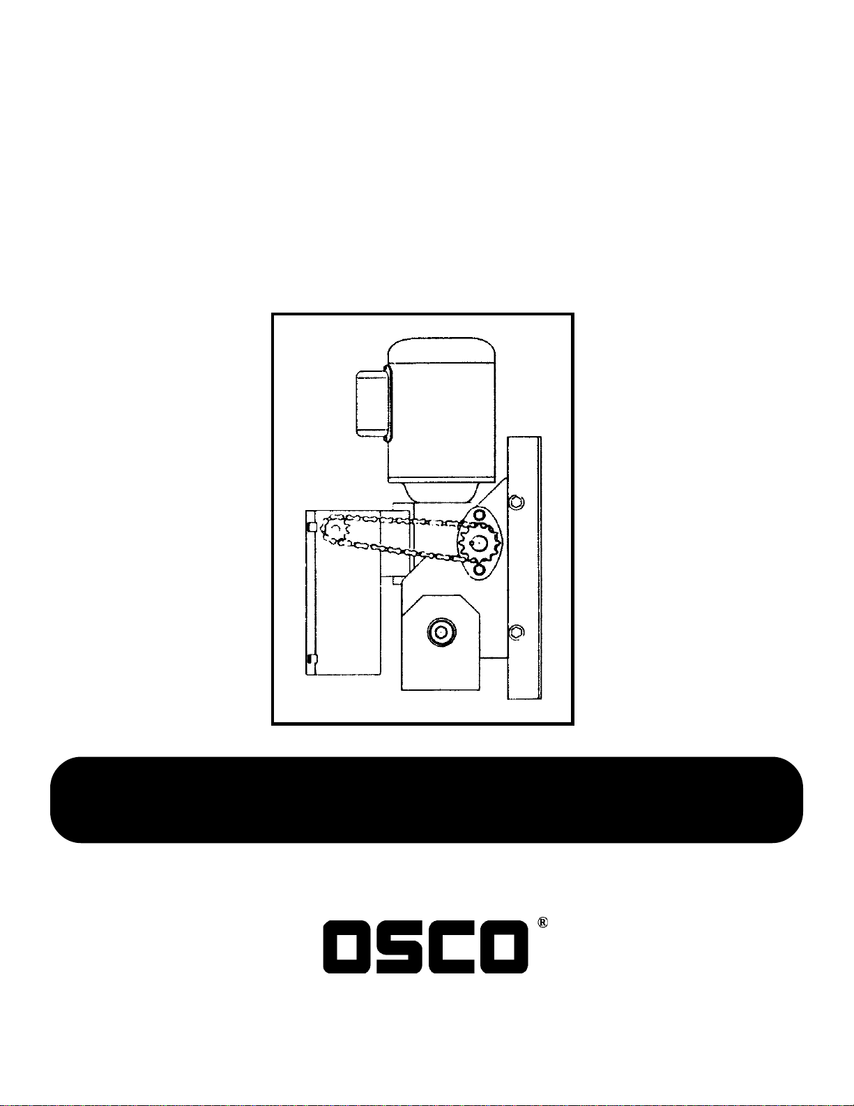
Model JG
Industrial Gearhead Jackshaft
Door Operator
Safety, Installation, and
Service Manual
OSCO requires use of an electric edge or photoelectric control
for pedestrian protection on all automatic or
remotely controlled door operators.
OPERATOR SPECIALTY CO., INC.
P.O. BOX 128, CASNOVIA, MI 49318
032498
1-5-98

OSCO Model JG Instructions Page 2
Safety Information and Warnings
Read all of the following before beginning to install the
Model JG operator:
1. Read the green “SAFETY INSTRUCTIONS” sheet
provided with the operator information. It’s extremely important that the safety warnings and
precautions be understood and followed by the
installing contractor. Leave all instructions with
the end user.
2. Do not attempt to operate the machine unless it is
completely installed as instructed.
3. The installation must be made in a neat and
professional manner, observing all rules of good
workmanship and personal safety.
4. All electrical connections to the power supply must
be made by a qualified and licensed electrician.
All local and national codes must be observed.
5. A power-disconnect switch should be located
within sight of the operator so that primary power
can be turned off when necessary.
6. Do not remove the operator cover unless you are
qualified to service this equipment and the power
is turned off. There are no user-serviceable parts
inside.
Features
Mechanical
• Continuous-duty industrial C-face motor
• Heavy-duty right-angle gear reducer
• Dependable roller chain drive
• Magnetic disc brake standard
• Emergency disconnect for manual operation
• Chain hoist operation with precision machine-cut bevel
gears
• Easily field converted to any mounting position
Electrical
• Easily adjustable rotary limit switches
• Heavy-duty 3-button control station
• Industrial across-the-line magnetic starter
• 24V control circuit
• Electric disconnect when chain hoist is engaged
• Adapted for pull cord, radio control, or photoelectric control
• Adaptable for reversing door edge
• Available with adjustable plug-in timer to close
CAUTION
OSCO STRONGLY RECOMMENDS USE OF AN
ELECTRIC EDGE OR PHOTOELECTRIC CONTROL
FOR PEDESTRIAN PROTECTION ON ALL AUTOMATIC OR REMOTELY CONTROLLED DOOR OPERATORS.
7. Install enclosed warning signs so as to be visible
to all persons passing near or through the door.
Children should never be allowed to play on, near, or
around a motorized door. Any control devices should be
placed so as to be inaccessible to small children.
8. Operate the door only when it is in full view.
The door should never be operated unless it is in visual
9. Do not permit children to play on or around the
sight of the user.
door.
10. Never reach through or around a door frame to
Warning signs must be installed on or near the door.
operate the door controls.
A pushbutton or keyswitch should not be installed within
11. Install all recommended safety equipment.
reach of the door or operator.
LIMITED ONE-YEAR WARRANTY
This electric operator is warranted for a period of one (1) full year from date of installation against defects in materials or workmanship. Any part, parts, or complete unit which fails because of such defects within this period shall,
at the manufacturer’s option, be repaired or replaced at no charge. The manufacturers will not be responsible for
transportation and/or field service charges.
This warranty is in lieu of all other warranties, expressed or implied, and shall be considered void if visible evidence implies recommended installation procedures and maintenance instructions were not followed.
1-5-98
OSCO Model JG Instructions Page 3
General Product Information
The Model JG gearhead jackshaft operator will electrically operate service doors, rolling grilles, sectional vertical-lift
doors, and sectional high-lift doors (minimum 24" of high lift). The operator is equipped with a chain hoist mechanism for
manual door operation in case of power failure. The mechanism is pre-installed and will operate in the vertical mounting
position. The chain hoist assembly may be moved for right-hand or left-hand operation as desired. A disconnect cable is
supplied for engaging the chain hoist from the floor level. This pull cable also electrically disconnects the control circuit.
Speed reduction is achieved by means of a heavy-duty wormgear in oil bath gear reduction unit, prelubricated at the
factory. Output speed is 43 RPM. The motor may be removed from the gear reducer without affecting limit switch adjustment or chain hoist operation.
Limit switches are actuated by rotary motion of a shaft driving threaded limit nuts, fully adjustable over a wide range.
A standard operator is supplied with six feet of #40 roller chain, a 14-tooth drive sprocket, and a 24-, 36-, or 48-tooth
driven sprocket. Other driven sprockets are available.
The standard operator is wired for control by an OPEN–CLOSE–STOP pushbutton station with momentary contact on the
OPEN, CLOSE, and STOP buttons or can be controlled either open or closed by optional 24V three-wire radio, pull cord,
or single-button station.
The Model JG gearhead jackshaft operator can be
mounted in a variety of positions.
Pre-Installation and Inspection
Unpack the carton, checking for possible damage during shipment. Damage claims must be filed with the freight carrier.
The following parts (one each) are included in the carton:
Power Unit Shaft Collar for Door Shaft
Hand-Operating Chain Sprocket Key
Hoist-Engagement Cable (attached to power unit) #40 Roller Chain (6 feet)
Cable Retaining Bracket #40 Master Link
Drive Sprocket (14-tooth, attached to output shaft) 3-Button Control Station
Driven Sprocket (includes set screws), one of— Wiring Diagram (in controller enclosure)
24-tooth for sectional doors Installation Manual
36-tooth for vertical-lift doors Spreader Arm
48-tooth for rolling-curtain doors Shaft Collar for Operator
Chain Wheel Rope Clip
Chain Guide Assembly Vent Plug
Check to make sure that the available power supply to be connected to the operator is of the same voltage, phase,
frequency, and wattage as indicated on the operator nameplate.
1-5-98
OSCO Model JG Instructions Page 4
Installation Instructions
Before installing the Model JG operator, read through the following steps and examine the drawings to help ensure a
satisfactory installation.
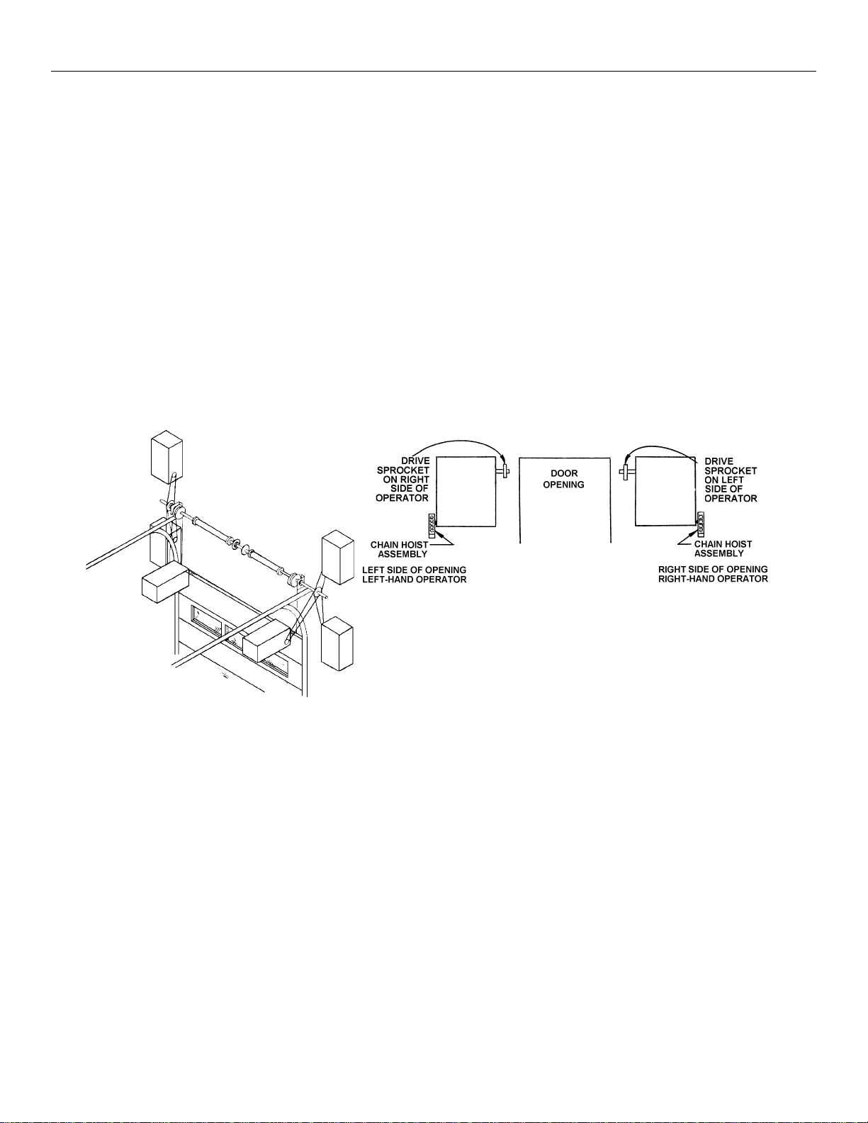
Operator Mounting—Right/Left Conversion
The Model JG operator may be mounted on either the right or left side of the door (see drawings below and on Page 3).
If it is necessary to move the chain hoist mechanism to the opposite hand, remove the shaft collar on the end of the
disconnect shaft, move the chain guide assembly and chain wheel to the opposite side, and replace the shaft collar.
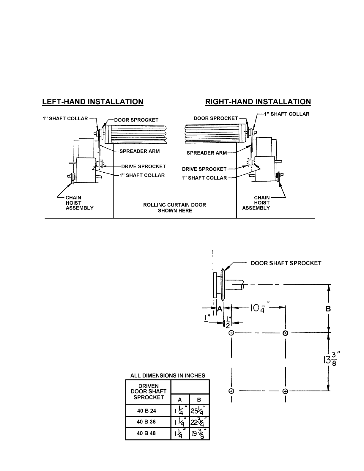
Wall Mounting
The operator should generally be installed below the door
shaft and as close to the door as possible. The optimum
distance between the door shaft and the operator output
shaft is 12–15 inches. A greater distance can be allowed if
conditions prevent installation as prescribed:
1. Using the center line of the door shaft as a reference
point, locate four mounting holes as shown in the drawing
and chart at right and below.
2. For a secure installation, the operator should be mounted
using 1/2" through bolts. If the wall is of such construction
as to prohibit the use of through bolts, lag bolts and
shields of sufficient size may be used. At this point, bolts
should be hand-tightened only.
1-5-98

OSCO Model JG Instructions Page 5
Attachment of Spreader Arm and Door Sprocket
1. Remove the drive sprocket from the JG operator
drive shaft.
2. Slide the proper door shaft sprocket onto the door
shaft, with the key inserted into the keyway.
3. Slide the spreader arm assembly onto the door shaft.
4. Make necessary adjustments in the spreader arm so
the lower end will slide onto the operator drive shaft.
5. Slide the drive sprocket onto the drive shaft and
tighten the set screw securely.
6. Position the door sprocket to be exactly in line with
the drive sprocket. Tighten the set screw securely.
7. Slide the 1" shaft collar onto the door shaft. Tighten.
8. Connect the two sprockets with #40 drive chain. If the
chain supplied is too long, shorten it to the proper
length, using a chain tool or by driving out the
necessary rivets with a punch. Lock the chain with
the #40 master link. Adjust the chain so there is no
more than 1/4" of slack when the chain is depressed
between the sprockets.
9. Attach the wall retainer bracket onto the wall for
securing the disconnect cable.
IMPORTANT
1. Power supply must be of correct voltage and phase.
2. Always disconnect power from operator before servicing.
3. Keep clear of door during operation.
Wiring Instructions
Read the section titled “Limit Switch Adjustment” on Page 7 before starting the following steps.
1. Consult local electrical codes for permanent wiring requirements at your installation site.
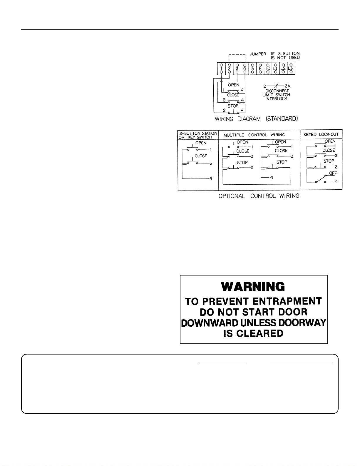
2. Remove the cover from the controller enclosure. Refer to the wiring diagram supplied inside for all electrical connections described below.
3. Bring the power supply to the controller and connect wires according to the wiring diagram. On three-phase machines,
incorrect phasing of the power supply will cause the motor to rotate in the wrong direction (open when CLOSE button
is pressed and vice versa). To correct this, interchange any two of the incoming three-phase leads.
NOTE: This unit must be properly grounded. A green grounding wire is supplied for connection to the power supply
grounding lead.
1-5-98
OSCO Model JG Instructions Page 6
Wiring Instructions (Cont’d)
4. Connect the three-button control station using four
wires, 14 GA or larger, to the terminal block in the
controller as shown in the upper illustration at right.
Connection of other types of control stations is shown
in the lower illustration.
5. The methods of installation for any passive auxiliary
control equipment, such as treadles or pull switches,
are at the discretion of the installer. Interconnections
between these devices and the operator should be to
the terminal block inside the controller. For electrical
connection points, refer to your wiring diagram.
Connection of an External Interlock Device
Circuitry is provided on all standard Model JG operators
for the connection of a two-wire external interlock device
that, when actuated, prevents the door from being
electrically operated. This should be wired into the
terminal block in the controller (see the upper diagram
at right, as well as the wiring diagram).
Nonstandard Wiring
If your operator is supplied with a nonstandard wiring type (see “Wiring Specifications,” on Page 13), for your particular
application refer to your wiring diagram for connection of all control equipment. If the wiring diagram is missing or has
been lost, call the factory for a replacement. Do not install any wiring or attempt to run this operator without consulting
the wiring diagram.
IMPORTANT NOTICE
This operator is supplied with a 3-button control
station (OPEN–CLOSE–STOP) accompanied by
the precautionary sign at right.
It is vital that the 3-button station be mounted
within sight but out of reach of the door and that
the warning sign be mounted adjacent to the 3button station.
The 3-button station must be connected so the STOP
circuit between terminals #2 & #4 is not bypassed.
Also, if additional 3-button stations are to be connected, the STOP buttons must be wired in series.
NOTE: A STOP button must be used when the instal-
lation has radio controls or a single button.
Desired Function Connecting Terminals
OPENING DEVICE #1 & #4
STOP #2 & #4
CLOSE #3 & #4
OPEN & CLOSE #4 & #5
SAFETY TO REVERSE #1 & #6
24V AC POWER #2 & #10
032498
1-5-98

OSCO Model JG Instructions Page 7
TURN OFF POWER TO THE OPERATOR
BEFORE MAKING ADJUSTMENTS!
Limit Switch Adjustment
IMPORTANT: To avoid danger of possible damage to the door and operator, limit switches must be adjusted to their
approximate positions BEFORE using the chain hoist to operate the door and BEFORE applying power
to the operator.
1. Open the cover of the controller enclosure.
There are two limit nuts on the threaded shaft
that move along the shaft as the operator
opens and closes the door (see the drawing
at right). When a limit nut nears the end of
the shaft, it activates two switches. LSO-1
and LSO-2 are the open limit switches; LSC1 AND LSC-2 are the close limit switches.
NOTE: Auxillary limit switches to control
other functions may also be present.
These are on a mounting bracket and
should not be confused with the open
and close limit switches, which are
mounted to the back of the controller
enclosure and are partially hidden
from view.
2. Manually raise the door to a nearly open
position (see Page 8, “Manual Operation”).
IMPORTANT: In Steps 3 and 4 below, LSO-2
and LSC-2 must be actuated
before LSO-1 and LSC-1. LSO-2
should be actuated three revolutions of limit shaft before LSO-1.
3. Depress the detent plate away from the slots in the limit nuts and manually rotate the left (open) limit nut until it
depresses the open limit switch levers. (You can hear a switch click when the switch contacts transfer.) One complete
turn will allow the door to move 4–6 inches. Release the the spring-loaded detent plate and be sure it is properly
locked into both limit nuts.
4. Manually lower the door to a nearly closed position and repeat Step 3 with the right (close) limit nut.
5. Manually move the door to a middle position to avoid door damage due to incorrect power supply phasing. PLACING
THE DOOR IN A MIDDLE POSITION NOW WILL PERMIT YOU TIME TO STOP THE OPERATOR IF YOU ENCOUNTER INCORRECT PHASING. On three-phase units, when power is applied the motor may run in the wrong
direction, causing the door to open when the limit nuts are traveling in the direction of the close limit switch—or vice
versa. In either instance, the limit nuts will travel past the limit switches, resulting in potential damage to both the door
and the operator. See Step 3 of “Wiring Instructions,” on Page 5 for correction of this problem.
1-5-98

OSCO Model JG Instructions Page 8
Operating Instructions
Electrical Operation
The Model JG is designed to provide years of trouble-free electrical operation of your door. The door can be operated by
means of the three-button control station or by other controls, when provided. If a reversing edge is wired into the operator, the door will reverse to the fully open position when it hits an obstruction during downward travel.
The motor contains a thermal overload protector to guard against motor overheating due to overload conditions. DO NOT
ATTEMPT TO BYPASS THIS UNIT. The overload protector will trip only under abnormal conditions. An out-of-balance
door or one that is binding in the tracks can produce such a condition. An incorrect installation may also cause such a
problem. If a protector continues to trip, consult a servicer or the factory.
Manual Operation
The Model JG may be used to operate the door manually if necessary. An electrical interlock will disable the motor when
the operator is used in such a fashion. To manually operate the door:
1. Pull the small disconnect cable to engage the hand chain and disengage the motor. This cable may be locked in
position by slipping the end through the cable-retaining bracket mounted on the wall.
2. Operate the door with the hand-operating chain.
3. The cable must be released from the retaining bracket before the door will operate electrically.
Service and Troubleshooting
A properly installed gearhead jackshaft operator will operate for many years with minimal service and maintenance. It is
important to note, however, that an improperly balanced or defective door can severely reduce the life of the operator.
The door should be checked and lubricated periodically as recommended by the manufacturer.
All bearings of the Model JG are oil impregnated or lifetime sealed antifriction bearings. The motor is factory lubricated
and requires no additional lubrication. A few drops of oil should be applied periodically to the moving parts of the manual
disconnect mechanisms. The oil lever in the gear housing should be inspected annually. If oil level is low, add lubricant
equivalent to Mobilube “C” 5AE140.
The following tips address common troubleshooting situations:
Motor does not run when OPEN or CLOSE button is pressed:
1. Building fuse blown or circuit breaker tripped. Replace fuse or reset breaker and check for cause.
2. Overload reset may be necessary. Check for cause.
3. Disconnect lever in position for manual operation. Return lever to position for electrical operation.
4. Check transformer secondary voltage. Check contactor coils for possible burnout. Check limit switches and interlock
switch. Inspect control station and all field wiring.
Door closes when OPEN button pressed and limit switches do not function:
1. Three-phase power supply is connected out of phase. Interchange any two incoming power supply leads.
2. Operator is mounted upsidedown. Consult factory.
1-5-98

OSCO Model JG Instructions Page 9
Service and Troubleshooting (Cont’d)
Operator does not shut off at fully opened or closed:
1. Limit nuts not porperly adjusted. See “Limit Switch Adjustment,” on Page 7.
2. Limit drive chain broken or inoperative. Replace the chain and check the mechanism.
3. Limit switch damage. Check limit switch operation and replace if necessary.
Ordering Replacement Parts
Use the numbers shown in the lists on the following pages to order all replacement parts.
1. Supply the serial number of your operator.
2. Specify the quantity of pieces needed.
3. Order by part number and name of part.
4. State whether to ship by freight, truck, parcel post, UPS, or air express.
5. State whether transportation charges are to be prepaid or collect.
6. Specify name and address of person or company to whom parts are to be shipped.
7. Specify name and address of person or company to whom the invoice is to be sent.
1-5-98

OSCO Model JG Instructions Page 10
1-5-98

OSCO Model JG Instructions Page 11
Model JG
Parts List #105 (Mechanical) OSCO Drawing #2120-122
Ref.
No. Part No. Description
1 2100-849 Main Frame Channel
2 2100-850 Mounting Angle
3 2100-851 Upper Spacer Bracket
4 2200-315 Radial Flange Bearing, 3/4"
5 2110-629 Bracket with Flange Bearing, 1"
6 2200-750 Gear Reducer, 40:1
8 2200-317 Sprocket, 40 B 14
2500-033 Standard 3-Button Station
2120-154 Spreader Arm Assembly
2120-155 Miter Gear with Brake Disc
9 2100-852 Miter Gear, 5/8” Bore
10 2100-853 Brake Disc
11 2100-854 Brake Shoe Mounting Plate
12 2100-855 Clamp Channel
13 2400-247 HHCS, 1/4”-20 x 2 1/4”
14 2200-320 Spring
15 2100-789 Connecting Link
16 2100-747 Brake Shoe
17 2100-743 Brake Pad
18 2100-843 Brake Shim
19 2100-838 Solenoid Bracket
20 2500-178 Solenoid, 115V
2500-177 Solenoid, 230V
2500-1351 Solenoid, 460V
21 2500-030 Disconnect Limit Switch
22 2100-856 Brake Release Bar
23 2100-792 Pivot Bracket
24 2100-857 Activator Lever
25 2100-858 Shifter Pawl
27 2100-859 Hoist Shaft
28 2200-321 Miter Gear, 3/4" Bore
29 2200-318 Disconnect Spring
30 2400-253 Spring Pin, 5/16" x 1 1/2"
31 2400-222 Key, 3/16" x 3/16" x 1"
32 2200-210 Shaft Collar, 3/4"
33 2200-290 Chain Wheel
35 2120-131 Chain Guide Assembly
2200-191 Hand Chain, per foot
2100-866 Cable Retainer
58 2200-474 #40 Drive Chain, 6'
34 2200-006 #40 Master Link
51 2200-066 Limit Sprocket, 48 B 20
55 2200-008 Limit Sprocket, 48 B 10
52 2200-249 #48 Roller Chain, 24 Links
88 2200-010 #48 Master Link
Motors
7 2500-2157 1/2 HP, 115/230 V, 1 Phase
2500-1603 1/2 HP, 230/460 V, 3 Phase
2500-2158 3/4 HP, 115/230 V, 1 Phase
2500-1604 3/4 HP, 230/460 V, 3 Phase
2500-2159 1 HP, 115/230 V, 1 Phase
2500-1605 1 HP, 230/460 V, 3 Phase
Door Shaft Sprockets
2200-227 40 B 24, Sectional Door
2200-376 40 B 36, Vertical-Lift Door
2200-423 40 B 48, Rolling-Curtain Door
6-18-02
1-5-98

OSCO Model JG Instructions Page 12
Models H, HB, JH, and JG
Parts List #147 (Electrical)
OSCO Drawing #2120-087
Ref.
No. Part No. Description
2520-231 Complete Controller, 115V, 1 Phase
(WD #2600-177)
1 2110-675 Controller Enclosure without Cover
2 2500-2084 Contactor, 24VAC, 4-Pole
3 2500-766 Transformer, 115/24VAC, 75VA
4 2500-541 Relay, 24VAC, 3PDT
5 2500-542 Relay, 115VAC, 3PDT
7 2500-1366 Timer (optional)
9 2500-001 Timer Switch (optional)
10 2500-030 Open Limit Switch, SP
11 2500-440 Close Limit Switch, SP
12 2500-071 Terminal Strip, 16-141
13 2300-052 Terminal Strip Label
14 2100-339 Limit Switch Bracket
15 2100-058 Limit Shaft Bracket
16 2100-056 Detent Plate
17 2200-030 Limit Nut
18 2100-057 Limit Shaft
19 2200-029 Flange Bearing, 1/2”
20 2200-008 Limit Sprocket, 48 B 10
Ref.
No. Part No. Description
21 2400-029 Push Nut
22 1600-088 Bushing
23 2100-060 Spacer
24 2200-028 Detent Spring
41 2400-001 S-Clip
42 2100-1701 Controller Enclosure Cover only
2500-442 Terminal Strip 3
2520-232 Complete Controller, 208/230V,
1 Phase, (WD #2600-178)
3 2500-767 Transformer, 208/230/24VAC, 75VA
5 2500-543 Relay 115VAC
2520-233 Complete Controller, 208/230V,
3 Phase, (WD #2600-144)
3 2500-767 Transformer, 208/230/24VAC, 75VA
2520-234 Complete Controller, 460V,
3 Phase, (WD #2600-144)
3 2500-768 Transformer, 460/24VAC, 75VA
10-31-01
1-5-98

OSCO Model JG Instructions Page 13
Wiring Specifications
1. Select from the chart at right the section
corresponding to the phase, voltage, and
horsepower of your operator.
2. The distance shown on the chart is measured in feet from the operator to the power
source. DO NOT EXCEED THE MAXIMUM
DISTANCE.
3. When large-gauge wire is used, a separate
junction box (not supplied) may be needed
for the operator power connection.
4. Select the gauge for control wiring from the
top chart below. If a greater distance is
required, our remote station interface is
suggested. Call the factory.
5. Wire run calculations are based on the
National Electrical Code, Article 430, allowing 5 percent voltage drop.
6. Supply voltage must be within 10 percent of
the operator rating under load conditions.
7. Connect power in accordance with local
codes.
8. The wire tables are based on standard
copper wire. Wire insulation must be
suitable to the application.
Volts Single Dual Wire Volts Single Dual Wire
& HP Unit Unit Gauge & HP Unit Unit Gauge
Single
Phase
Phase
115V 120 60 12 208V 475 240 12
1/3HP 485 240 6 1/3HP 1915 960 6
115V 125 60 12 208V 370 185 12
1/2HP 500 250 6 1/2HP 1485 740 6
115V 65 30 12 208V 260 130 12
3/4HP 265 130 6 3/4HP 1055 600 6
115V 55 30 12 208V 225 115 12
1HP 225 115 6 1HP 910 455 6
Three
208V 650 325 12 460V 2850 1425 12
230V 1035 515 10 4535 2265 10
1/3HP 2615 1310 6 1/3HP 11465 5730 6
USE COPPER WIRE ONLY
Power Wiring
Max Distance (ft) Max Distance (ft)
190 95 10 230V 760 380 10
305 150 8 1200 600 8
200 100 10 230V 585 295 10
315 160 8 935 465 8
105 50 10 230V 415 205 10
165 80 8 665 330 8
85 45 10 230V 360 180 10
140 70 8 570 285 8
1645 825 8 7210 3605 8
NOTE: If the power run is over 500 feet,
consult your power utility company
about possible power drops overhead
or underground.
Control Wiring
Wire
Volts Max Distance (ft) Gauge
24V 250 14
350 12
Over 350 ft, see interface chart.
Control Wiring w/ Interface
Wire
Volts Distance Over (ft) Gauge
24V 350 14
208V 620 305 12 460V 2705 1350 12
230V 985 490 10 4305 2150 10
1565 780 8 6850 3425 8
1/2HP 2485 1240 6 1/2HP 10895 5445 6
208V 440 220 12 460V 1935 965 12
230V 700 350 10 3075 1540 10
1115 558 8 4890 2445 8
3/4HP 1775 885 6 3/4HP 7780 3890 6
208V 345 170 12 460V 1595 795 12
230V 545 275 10 2535 1265 10
870 435 8 4030 2015 8
1HP 1380 690 6 1HP 6405 3205 6
208V 235 120 12 460V 1040 520 12
230V 380 190 10 1655 825 10
1 1/2 600 300 8 1 1/2 2635 1315 8
HP 955 480 6 HP 4190 2095 6
208V 180 90 12 460V 795 400 12
230V 290 145 10 1265 635 10
460 230 8 2015 1005 8
2HP 730 365 6 2HP 3205 1600 6
1-5-98

OSCO Model JG Instructions Page 14
Instructions for Optional Jackshaft Chain Hoist
The jackshaft operator’s optional chain hoist is for use in case
of power failure or malfunction of the automatic operator. When
not in use, the chain and engagement cable should be held in
the retainer bracket up against the wall and to the side of the
doorway.
To use the optional chain hoist:
jammed.
1. Be sure the door and track are in good working order and not
wall bracket.
2. Remove the chain and engagement cable from the retainer
hoist. This also disengages control power from the door
operator.
3. Pull downward on the engagement cable to engage the chain
The pre-installed clamp on the cable should be slid under the
4. Place the engaged cable back in the wall retainer bracket.
bracket shelf to hold the chain hoist engaged.
door. To avoid over-running the limit switches, be sure not to
raise the door beyond the point at which it would normally
stop if automatically powered.
5. Pull on the chain with a steady medium speed to raise the
and out of the retaining wall bracket.
6. To re-engage the operator, ;pull the disconnect cable down
1-5-98

OSCO Model JG Instructions Page 15
1-5-98

OSCO Model JG Instructions Page 16
1-5-98

OSCO Model JG Instructions Page 17
1-5-98
 Loading...