

Page 1
ID: 1588 / ver. 205
1
Page 2

ID: 1588 / ver. 205
2
Table of contents
1. GENERAL DESCRIPTION .............................................................................................................................................. 3
1.1 FRONT PANEL DESCRIPTION ............................................................................................................................................. 3
1.2 BACK PANEL DESCRIPTION .............................................................................................................................................. 4
2. OPERATION ...................................................................................................................................................................... 4
2.1 SETTING UP THE TSM-300 .............................................................................................................................................. 4
2.2 TAKING A MEASURE ........................................................................................................................................................ 4
2.3 READING THE DISPLAY .................................................................................................................................................... 5
3. USING THE MENUS ......................................................................................................................................................... 6
4. THE MEMORY .................................................................................................................................................................. 6
4.1 CLEARING A MEMORY LOCATION .................................................................................................................................... 7
4.2 CLEARING THE ENTIRE MEMORY ..................................................................................................................................... 7
5. USING THE PRINT OR TRANSMIT FUNCTION ........................................................................................................ 7
6. DISABLING REFLEX FREQUENCIES ....................................................................................................................... 10
7. CALIBRATING THE PROBE ........................................................................................................................................ 11
8. CHOOSING NUMBER OF TYMPANOGRAM SWEEPS .......................................................................................... 12
9. HOW TO CLEAN THE PROBE ..................................................................................................................................... 13
10. OPERATION OF THE TSM-300 .................................................................................................................................. 14
TECHNICAL SPECIFICATIONS ...................................................................................................................................... 15
WARNING AND SAFETY NOTICES ............................................................................................................................... 16
MAINTENANCE & CALIBRATION ......................................................................................................................................... 16
CLEANING ........................................................................................................................................................................... 16
SHIPPING RECOMMENDATIONS ............................................................................................................................................ 16
DISPOSAL ............................................................................................................................................................................ 16
SYMBOLS ............................................................................................................................................................................. 17
EMC ....................................................................................................................................................................................... 18
RESPONSIBILITY OF THE MANUFACTURER ........................................................................................................... 20
MANUFACTURER .............................................................................................................................................................. 20
Page 3

ID: 1588 / ver. 205
3
1. General description
The OSCILLA® TSM-300 is designed for tympanometric screening.
This screening is divided into two different tests. First, a tympanogram is recorded, which measures the mobility
of the tympanic membrane and middle ear. Second, an ipsilateral acoustic reflex test is recorded, which
measures the contraction of the stapedius muscle in response to loud sounds.
The test results are displayed on a graphic LCD display while they are recorded. When the test is completed it is
stored in the memory. Tests may be printed out using an external printer connected to the tympanometer, or
transmitted to a PC through a serial cable. TSM-300 may store results from 20 tests.
For configuring and calibrating the device, there is a menu system with various functions. These are setup
options, calibration and clearing memory. In the daily use it is not necessary to use the menu system, the
functions for daily use are linked directly to dedicated keys, to make them easy accessible.
1.1 Front panel description
Display – Show actual measurements, menus and messages.
Left button – Change between left and right ear.
Up / Down buttons – Change of ID number, for saving of tympanogram and reflex.
Right button – Print a measurement or transmit data to PC.
Menu button – Activate menu screen on the device.
Page 4
ID: 1588 / ver. 205
4
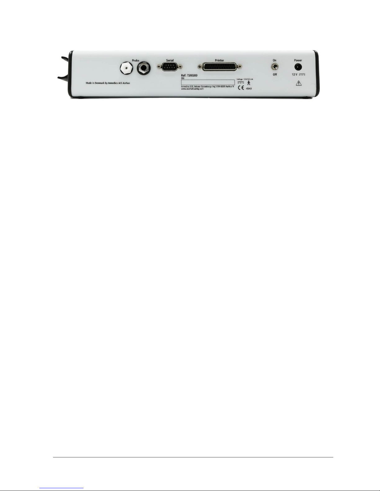
1.2 Back panel description
PROBE – Connectors for the probe’s combined jack and air plug.
SERIAL – Serial RS232 port for data transfer to a PC or printout on a serial printer.
PRINTER – Connector for parallel printer.
ON/OFF – Switches the device ON / OFF.
POWER – Connector for power supply.
2. Operation
This section describes how to set up and use the tympanometer.
2.1 Setting up the TSM-300
Setting up the tympanometer is quite easy and quick.
Place the tympanometer on a table and connect the probe’s combined air and jack plug to the back of the
device, where the label “PROBE” is printed.
Connect the mains adapter’s cable to the socket marked “POWER” and insert the adapter in a mains outlet and
switch on the mains.
Switch on the device at the switch next to the POWER socket. The tympanometer will start with a brief start up
screen on the display. Then the main screen appears and the device is ready for use.
To ensure correct measurement, you should calibrate the device now, using the calibration cavity chamber set.
See section “7. Calibrating the probe”.
2.2 Taking a measure
Before taking a test on a patient, mount a new rubber ear tip on the probe that fits the patient’s ear size. Ensure
the patient’s ear canal is clean and not clogged by ear wax. Also remove any hair or other objects that can
prevent an air tight seal between the probe tip and the auditory canal.
Choose on the TSM-300 which ear to test, left or right. (Use left arrow key to change with).
Choose the desired ID location to save the measured data. (Use up / down keys to change with).
Place the probe’s tip in the patient’s auditory canal and press gently. The probe must follow the auditory canal in
a line, to obtain the best performance.
The tympanometer will start automatically, and begin running the pump and draw the tympanogram. This is
drawn in real time while the test runs. Keep an eye on the message in the upper right corner of the display. It
should say “TYMP” for a few seconds while measuring. If it says “LEAK” or “BLOCKED”, adjust the probe
position slightly. If you have trouble with constantly getting a “LEAK” message, try to remove the probe and let
the pump return to its starting position, then insert the probe again. The pump position is displayed in the lower
right corner as a little vertical bar marked “PUMP”.
Page 5

ID: 1588 / ver. 205
5
When the tympanogram is completed, the values in the right box are updated, and the pump seeks to the point
of maximum compliance. Then the reflex test is carried out. Be sure to keep the probe very still while this is
running, even small movements will add noise to the reflex graph.
After the reflex test, a “REMOVE” message is shown, and the probe can be removed. The test result is now
stored in the memory at the selected ID position.
2.3 Reading the display
After having carried out a measurement you can see the results on the display. The picture below shows a
typical measurement of a normally functioning ear.
The picture is divided into three main sections. The tympanogram is shown in the upper section, the reflex test in
the lower, and to the right there is a box with four values obtained from the tympanogram.
Tympanogram:
The tympanogram shows the graph of the middle ear compliance, as a function of pressure. The X-scale is the
pressure, given in deka Pascal (daPa). This is nearly the same as millimetres of water (mmH2O), as 1.02
mmH2O is approx. 1.0 daPa. The Y-scale is the compliance given in equivalent volume of air, in millilitres. Inside
the tympanogram frame is a box. If the peak of the measured graph is inside this box, the ear condition can be
considered normal.
Reflex test:
This shows the ear’s reflex response to the 5 test tones. Stimulus tones of 105 dB SPL at 500, 1000, 2000, 3000
and 4000 Hz are presented as short bursts. If a change in compliance greater than 0.05 ml is detected, a reflex
is considered present. Because this is an extremely small compliance change, any movement of the probe
during the test may produce an artefact (false response). If the tympanometric results display any abnormal
findings, the results of the acoustic reflex testing may be inconclusive and should be interpreted with care.
Theoretically, a compliance peak is necessary to observe a reflex at peak pressure.
Measurement box:
In the box to the right, the numerical measurements are displayed:
MID EAR PRESS indicates the pressure with the highest measured compliance (in the example 0 daPa).
EAR VOLUME indicates the volume of the section between the ear tip and the eardrum in ml (example 1.87 ml).
COMPLIANCE indicates the value of the compliance from the tympanogram, in ml (example 0.97 ml).
TYMP WIDTH is the width of the peak at half the peak height, related to -200daPa (example 46 daPa).
In addition to the three main sections, the following other items appear:
Status indicator:
In the top right corner, the status indictor is shown. This tells you what state the device is in. The message can
be one of the following:
READY indicates that the instrument is ready for testing.
BLOCKED indicates that probe tip is blocked. This may be caused by misalignment of the probe in the ear.
LEAK indicates that the air seal between the probe and the ear is not tight.
TYMP indicates that the tympanometric test is in process.
REFLEX indicates that the reflex test is in process.
REMOVE indicates that the test is finished and the probe can be removed.
Page 6
ID: 1588 / ver. 205
6
Key related texts at the bottom of the picture:
Above the left key, the word LEFT or RIGHT indicates the chosen ear at the moment.
Above the up and down keys, the ID number for storing data is shown.
Above the right key, the word PRINT or TRANSMIT is shown. This indicates if a press on the key will print out
the test, or transmit it to a PC.
Pump indicator:
In the lower right corner a pump indicator is shown. This follows the physical pump that delivers the pressure
during the tympanogram measurement. The pump has a limited travel range, and it may happen that it runs all
the way to the limits and is unable to deliver more air. This will cause the “LEAK” message to appear. If this
happens repeatedly during a test, remove the probe and wait for the indicator to return to the starting position.
3. Using the menus
To use the menu system, press the MENU key. This enters the main menu, and the arrow keys are now used to
control the menu.
Left button – Used to go back in the menu, or adjust a setting
Down button – Moves the menu selection bar down
Up button – Moves the menu selection bar up
Right button – Used to enter the selected menu, or adjust or activate the selected menu item
Menu button – Used to enter or leave menu
4. The memory
The tympanometer has a built in memory for 20 complete tests. Each test is stored under an identification
number from 1 to 20. A stored test includes all data seen on the display, both the graphic and numeric data for
the tympanogram and the reflex test graph. These data are stored for both ears.
After taking a test, it is stored under the currently selected ID number and the currently selected ear. The ID
number is displayed in the bottom of the screen, above the up and down arrow keys. These two keys are used
to select the ID number. The selected ear is displayed above the left arrow key, and this key is used to toggle
between left and right ear. When a new ID is selected, or the ear is changed, the data from the new location is
recalled to the display. If a test is performed, the stored data is overwritten with the new test data.
Page 7
ID: 1588 / ver. 205
7
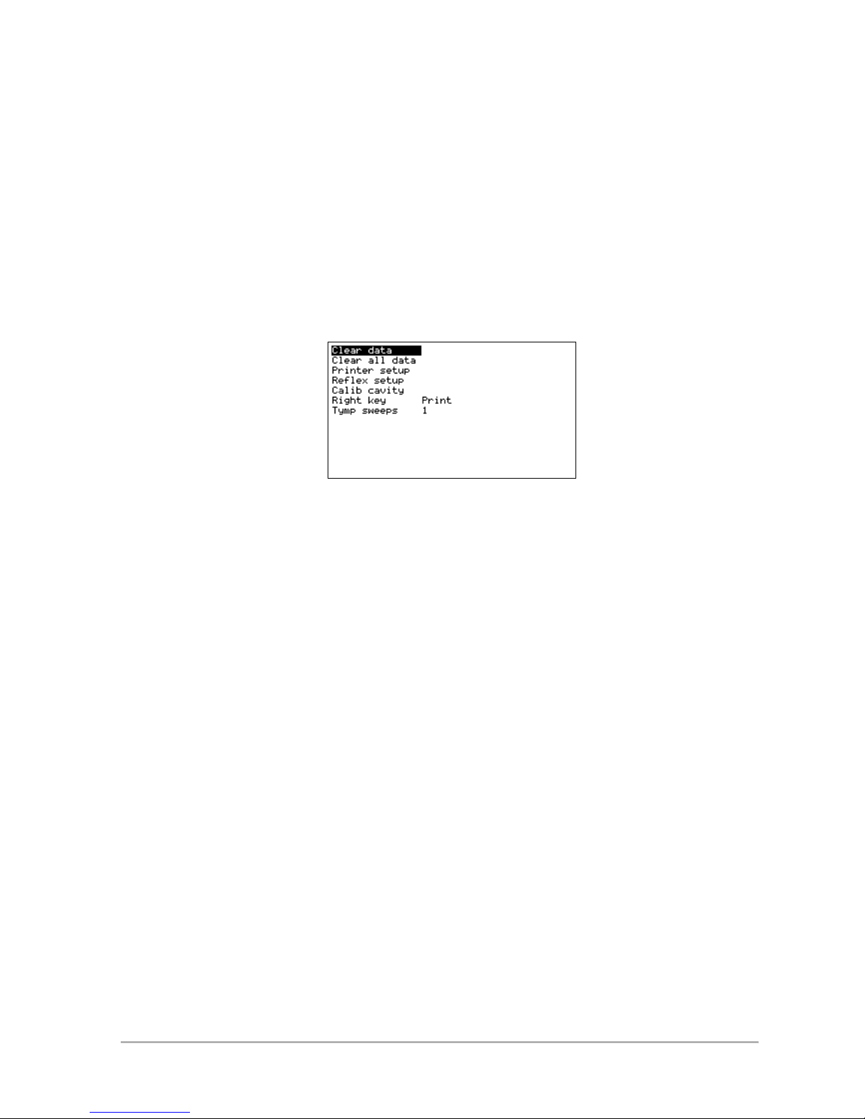
4.1 Clearing a memory location
Clear data
Normally it is not necessary to clear the memory, because a new test is overwriting
old data. But if it is desired to clear an ID location, for example because you only
want to measure one ear, and therefore wants to have the other ear cleared, it can
be done inside the menu. Press the MENU button, select the Clear data item and
press and hold down the right arrow key for one second. After this time the selected
ID location is cleared. This takes a few seconds and ends with a brief “Done”
message. The ID location that is cleared is the one that is selected in the main
screen.
Clear all data
Printer setup
Reflex setup
Calib cavity
Right key
Tymp sweeps
4.2 Clearing the entire memory
Clear data
If you want to erase all the tests stored, enter the menu and select the Clear all
data menu item and hold the right arrow key for one second. This erases all the
ID locations while displaying the ID number of the location currently being erased,
ending with a “Done” message. This takes about a minute to complete.
Clear all data
Printer setup
Reflex setup
Calib cavity
Right key
Tymp sweeps
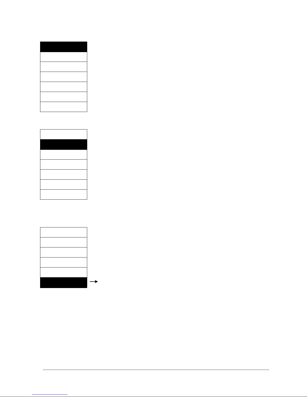
5. Using the PRINT or TRANSMIT function
Clear data
Clear all data
The tests stored in the memory can be exported in
two ways. They may be printed out on a printer
connected directly to the tympanometer, or they
may be transmitted to a connected PC. This is
done by pressing the right arrow key. To chose if
it should be the PRINT or the TRANSMIT function
that is activated when the key is pressed, go into
the menu and select the “Right key” item at the
bottom of the menu. Then toggle between the two
functions with the right arrow key. When you leave
the menu, the chosen function is shown above the
Printer setup
Reflex setup
Calib cavity
Serial transmission
Tymp sweeps
Print
5.1 Connecting a printer or PC
Before data can be printed or transmitted, the correct cable must be connected. A printer can be connected
either to the parallel port marked “PRINTER”, or the serial port of the tympanometer, depending on the printer
type. Most printers use the parallel port, but a few uses the serial port, for example the small Kyosha thermo
printer. Turn off the tympanometer and the printer and attach the printer cable to the printer and the
tympanometer.
A computer is always connected to serial port. The cable used is a “null-modem” cable. It should be connected
between the serial port on the tympanometer and the serial port on the computer. Some computers do not have
a serial port. In this case, a USB-to-serial converter can be used to add a serial port to it.
Clear data
Clear all data
Right key
Page 8

ID: 1588 / ver. 205
8
5.2 Transmitting the test data to a PC
Test data can be transmitted to a PC running Inmedico’s AudioConsole program, or other programs that is able
to read the transmitted format. This is done simply by pressing the right arrow key, while the key is set to
TRANSMIT mode. After a short moment the test should appear in the AudioConsole program.
5.3 Identification key
The serial port is also used for transmitting an identification key to the PC. This happens automatically when the
device is turned on. It tells the PC program that a tympanometer is present so it can switch to tympanometer
mode. Note that this key is not transmitted if the serial port is set up to be used to print through.
5.4 Printing the test results
Printing a test is also started by pressing the right arrow key, but the key’s mode should be set to PRINT. To
make printout work successfully, the device will have to be set up to the correct type of printer. This is done in
the printer setup menu.
5.5 Setting the printer type
The tympanometer supports 4 printer types. To change the printer type, enter the menu and go into the “Printer
type” item and:
Select MATRIX if the printer is an Epson compatible printer.
Select IBM PRO if the printer is an IBM PRO or compatible printer.
Select THERMO if the printer is a Kyosha thermo printer. This setting may work with other small printers too.
Select HP if the printer supports PCL-2 to PCL-5, language.
Some printers may emulate other printers. For example, many laser printers other than HP will work with the HP
setting, because they use the same language. Also, some inkjet printers will work with MATRIX or IBM PRO
setting. Other inkjets, like HP DeskJet printers, will usually work with the HP setting.
The printer’s manual should provide information about what language the printer uses, or which other printers it
can emulate. If this information is not available, you can just try out the different printer type settings and see if it
works. It does not harm anything to select the wrong type.
Clear data
Clear all data
Printer setup
Printer type
MATRIX
Reflex setup
Printer Port
THERMO
Calib cavity
Carriage return
IBM PRO
Right key
Printer margin
HP
Tymp sweeps
Note that printers designed specially for Windows or require bidirectional communication will not work when
connected directly to the tympanometer. But it is perfectly possible to connect them to a PC running the
AudioConsole program, and transmit the tympanogram data to the PC and print them out from there.
5.6 Printer port
The tympanometer can use both serial and parallel printers. Only a few uses serial port, so normally the port
used for printout should be set to parallel. An example of a serial printer is the small portable Kyosha thermo
Printer setup
Printer type
Page 9

ID: 1588 / ver. 205
9
printer. Note than when the serial port is selected for printout, the tympanometer will not transmit its identification
key at start up.
Clear data
Clear all data
Printer setup
Printer type
Reflex setup
Calib cavity
Carriage return
Serial
Right key
Printer margin
Tymp sweeps
5.7 Printer margin
The left margin of the printout can be adjusted in the setup. This allows the printout to be shifted to the right, to
give space for holes for inserting in a ring binder. Just be sure not to set it too wide, it may cause clipping of the
right side of the printout. The “Test printer” item will print out a test image with the selected margin. To leave the
menu, press MENU.
Clear data
Clear all data
Printer setup
Printer type
Reflex setup
Printer Port
Calib cavity
Carriage return
Right key
Tymp sweeps
Test printer
5.8 Turning carriage return on and off
Carriage return is used to force a carriage return command to the printer. If the printer does not advance the
paper, the carriage return should be set to on. This setting has no effect when printer type is set to HP.
Clear data
Clear all data
Printer setup
Printer type
Reflex setup
Printer Port
Calib cavity
Carriage return
Right key
Printer margin
Off
Tymp sweeps
Printer setup
Printer Port
Parallel
Printer setup
Printer margin
Printer Margin 0
Printer setup
Carriage return
On
Page 10

ID: 1588 / ver. 205
10
5.9 Solving printer troubles
When a printout is started with the right arrow key, a message is shown on the display, telling which printer type
and what port is used for the printout. If the parallel port is used, and the printer is not working for some reason,
you may get a “Printer error:” message after a while. If this happens, check that the printer has not run out of
paper, that it is turned on, that it is ‘online’, that the printer cable is connected etc. The error message is removed
by pressing the right arrow key again.
If the printer does print, but the printout is wrong, it is most likely that some of the settings in the tympanometer
need to be changed. The printout may be wrong in some different ways. If there is no recognizable graphics
present, but only strange letters and characters, it is most likely because a wrong printer type has been selected.
If you do see the graphics, but there are regular horizontal blank lines in it, try to disable the Carriage return
function in the printer setup menu. This may also happen if an IBM Pro Printer is selected in the setup, and an
Epson compatible printer is used, or vice versa. If the printer just advances the paper without printing anything, it
may help to enable Carriage return in the printer menu.
When using a serial printer like the Kyosha thermo printer and it prints strange characters, again it may be
because a wrong printer type is selected. But it may also be because the Right key mode is set to TRANSMIT,
and thereby send test data intended for a PC to the printer.
6. Disabling reflex frequencies
If it is desired not to measure stapedius reflex at all the 5 available frequencies, some of them can be disabled.
Press the MENU key, select the “Reflex setup” item and press the right arrow key. Now you can enable and
disable the individual frequencies by pressing the right arrow key. If the bottom item “On/Off” is disabled, the
whole reflex test is disabled and will be skipped over when a test is performed.
Clear data
Clear all data
Printer setup
500 Hz
Calib cavity
1000 Hz
Right key
2000 Hz
Tymp sweeps
3000 Hz
4000 Hz
On/Off
When returning to the main screen, the frequencies that have been disabled will be shown with a line over the
frequency number to indicate they will not be used.
Reflex setup
Page 11

ID: 1588 / ver. 205
11
7. Calibrating the probe
Clear data
Clear all data
Printer setup
Reflex setup
Calib cavity
0.5 ml
Right key
2.0 ml
Tymp sweeps
5.0 ml
Store
You should adjust your tympanometer before use, to the actual atmospheric pressure by means of the enclosed
calibration cavity chamber set. The calibration is very easy and takes only a short while.
1. Enter the Calib cavity item from the main menu.
2. Put the probe tip with ear tip into the hole of the test cavity labelled 0.5 ml and then press Right key.
3. Press the Down key to select 2.0 ml.
4. Put the probe tip with ear tip into the hole of the test cavity labelled 2.0 ml and then press Right key.
5. Press the Down key to select 5.0 ml.
6. Put the probe tip with ear tip into the hole of the test cavity labelled 5.0 ml and then press Right key.
7. Press the Down key to select Store, and then press Right key.
If successful calibration is done, the text “OK, Calibrations stored” is displayed.
To return to the main screen press Left key twice.
ATTENTION:
If the error message "ERROR, REDO CALIBRATION" appears when activating Store, please check if the
openings of the calibration chamber and the probe tip are clean and re-calibrate the probe. Be sure to use the
correct cavity volumes. If the error message appears again, the probe or the instrument is probably defective.
Contact your service to get help.
Calib cavity
Page 12

ID: 1588 / ver. 205
12
8. Choosing number of tympanogram sweeps
When a tympanogram is recorded, the device sweeps the pressure between negative and positive. This is done
a number of times before it stops. This number can be set to a value between 1 and 10 in the main menu, under
the menu item “Tymp sweeps”.
Clear data
Clear all data
Printer setup
Reflex setup
Calib cavity
Right key
Tymp sweeps
1
If you want a quick test without repeatedly sweeping and graph redrawing, set the value to 1. The device will
then build up a negative pressure, take one sweep from negative to positive, and stop. If you want to watch a
more dynamic live picture of the tympanic membrane’s behaviour, set the number to a higher value. The device
will then sweep the selected number of times before ending the measure.
Tymp sweeps
Page 13

ID: 1588 / ver. 205
13
9. How to clean the probe
If the probe becomes clogged in the hole at the tip, clean it using the following procedure.
Probe head
To remove the ear tip, hold firmly but carefully on the probe head and then remove the old ear tip and replace it
with the new one.
If there is ear wax or other things in the probe head, then the probe can be dismounted for better cleaning.
Please do as shown in the next figures.
Probes handle Probe head
To remove the probe head, hold firmly but carefully on the probe handle and then gently pull the probe head off.
Be careful not to bend the small metal pipe. If anything is stuck inside the metal pipe
be careful not to push it further in when removing it.
The probe head can be cleaned in lukewarm water and soap.
Page 14

ID: 1588 / ver. 205
14
10. Operation of the TSM-300
When recording a tympanogram it is done in a slightly different manner than usual. Normally only one sweep of
pressure change is used, usually from negative to positive. The TSM-300 uses a few cycles of pressure change
in both directions. While these cycles are running, it will simultaneously display the tympanogram in real time on
the display. This produces a ‘live’ picture that may be useful in some situations. It also assists in positioning the
probe correctly in the ear. It is possible to change the number of sweep cycles the device performs before it
accepts the measurement. This is done in the main menu under “Tymp sweeps”.
Another difference is that the 226Hz measuring tone is kept at a constant signal level instead of changing the
level during a measure. Often a feedback system is used to adjust the sound level dynamically so it tracks the
ear canal volume and kept at 85dB independently of the volume. This system’s tracking control signal is then
used to determine the volume. In the TSM-300 such a system is not used, the measuring tone is instead
calibrated to give 85dB in a 2cc cavity. When a smaller or larger cavity is applied, the sound level measured by
the probe’s microphone changes, and this change is used directly to determine the volume.
The reflex test is, like the tympanogram, displayed live while it is recorded. This gives a good chance of
observing if noise from unintended movements of the probe occurs, because the noise will show up instantly on
the live graph during a test.
Page 15

ID: 1588 / ver. 205
15
Technical specifications
Standards: EN 60601-1: 1996
EN 60601-1-2:2001
EN 60645-5:2005
Classification: Group 1, class A EN 60601-1-2:2002
Medical CE- mark: Inmedico A/S is approved for medical CE marking, by DGM.
Identification number 0543
Tympanometer:
Test frequency: 226 Hz
Tolerance frequency: ± 1%
Test Level: 85dB SPL in 2ml ± 3dB
Pressure: +200 to -300 daPa
Volume range: 0.1 to 6.0 ml
Reflex measurements:
Test frequencies: 500 Hz, 1 kHz, 2 kHz, 3 kHz, 4 kHz ± 2%
Test method: ipsilateral
Test Level: 105dB SPL in 2ml ± 3dB
Supply: 230 VAC / 12 VDC ±10 %
Dimension: 225 mm x 180 mm x 55 mm
Weight: Approx. 1000 g
Warm-up time: < 10 minutes.
Operating temperature: +15 to +35 degree C.
Humidity: 30 % to 90 %
Surroundings pressure: 98 to 104 kPa
Calibration cavities: 0.5 ml, 2.0 ml and 5.0 ml, the volume tolerances shall be ± 2 % or 0.05 cm3,
whichever is greater.
Included parts: 1 PSU, 1 user manual, 1 calibration certificate, 1 calibration cavity set and 1 probe
with 6 sizes of tips.
Accessories: Carrying bag, thermo printer.
Page 16

ID: 1588 / ver. 205
16
Warning and safety notices
Maintenance & calibration
Cleaning
Shipping recommendations
Disposal
Page 17

ID: 1588 / ver. 205
17
Symbols
Page 18

ID: 1588 / ver. 205
18
EMC
Page 19

ID: 1588 / ver. 205
19
Page 20

ID: 1588 / ver. 205
20
Responsibility of the manufacturer
Manufacturer
Page 21

ID: 1588 / ver. 205
21
 Loading...