

Page 1

T830/T840
Screening Tympanometer
User Guide
Doc. No.7-50-1810-EN/03
Part No.7-50-18100-EN
Page 2

Copyright notice
© 2016,2017Inmedico A/S.All rights reserved. Oscilla® is a registered trademark of Inmedico A/S inthe U.S.A. and/or other countries.
Version release date
2017-10-31 (167384)
Technical support
Please contact your supplier.
Inmedico A/S - T830/T840
2
Page 3

Table of Contents
1 Overview
4
2 Intended use
5
3 Unpacking
6
4 Installation
6
5 The probe and the contralateral phone
8
6 Tympanometry testing using the device
11
7 Testing using the Oscilla® AudioConsole software
17
8 Tympanometry testing using AudioConsole
17
9 Device setup using AudioConsole
18
10 Service, cleaning and calibration
18
11 Technical specifications
22
12 Standards and warnings
28
13 Other references
31
14 Manufacturer
31
3
User Guide
Inmedico A/S - T830/T840
Page 4
1 Overview
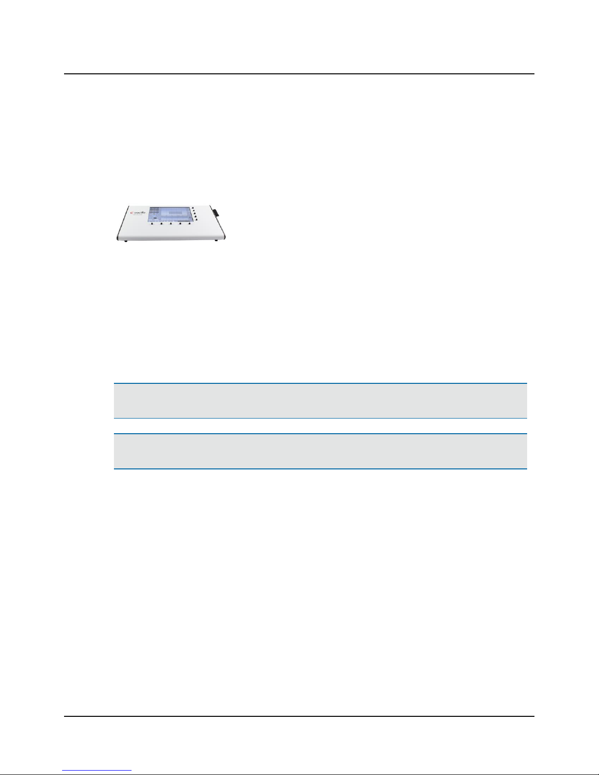
This User Guide describes the Oscilla® T830/T840 tympanometer.
T830/T840 tympanometer
T830/T840 is a screening tympanometer for conducting middle ear measurements on patients.
T830/T840 is an auditory impedance tester that is intended for changing the air pressure in the external auditory canal
and measuring and graphing the mobility characteristics of the tympanic membrane to evaluate the functional condition of
the middle ear.
T830/T840 uses technologies which are highly effective for diagnostic and screening purposes. Tympanometry and acoustic
reflex measurements measure the mechanical response of the middle ear and form a basis for evaluating whether the
related physiological structures are functioning correctly or not.
Operating the device
You can operate the device either as a stand-alone unit using the front panel buttons and display, or from the Oscilla®
AudioConsole PC software.
Note•If you are controlling the devicefrom the Oscilla®AudioConsole PC software, see the Oscilla®AudioConsole
User Manual.
Note•Oscilla®AudioConsole PC software is an optional accessory, which requires a license key. If you wish to use
AudioConsole, please contact your distributor.
Probes
The device supports the following probes:
• The test probe
• A contralateral phone or insert phone (T840 only)
Supported tests
The device supports the following tests:
• Tympanometry
• Ipsi- and contralateral reflex (contralateral: T840 only)
T830/T840 - Oscilla®AudioConsole interfacing
The device is designed to operate with the Oscilla®AudioConsole PC software.
From AudioConsole you can perform tests, monitor test results, store data, and print reports.
Inmedico A/S - T830/T840
User Guide
4
Page 5

Printing test results
The device can be connected to a printer (optional accessory) for printing test results.
When the device is used in connection with AudioConsole, test results can be printed either on the printer connected to
the device, or from the AudioConsole software.
2 Intended use
Measuring acoustic impedance/admittance in the human external acoustic meatus using a stated probe tone or other
probe signals.
Users: Audiologists, ENTs and other health care professionals with knowledge of immittance meas-
urements.
Use: Screening tympanometry and reflex measurements.
Patient population: Children (from 6 months of age) and adults.
Contraindications
Warning• If the patient is troubled by the test, stop the test. The test is interrupted immediately. Already measured
results are kept.
Warning• Look into the ear canal. It is strongly recommended that you perform an otoscopy to assess the status of
the outer ear before you insert the probe. If the ear canal is blocked, this may affect the result of the test. Clean the
ear canal if needed. Make sure that there is no residual fluid in the patient's ear after cleaning or wax removal.
Warning• Testing should not be performed on patients displaying the following symptoms without the approval of a
medical doctor:
• If there is discharge in the ear
• If the patient recently has undergone middle ear surgery
• If the ear canal is occluded
• If the patient suffers from acute trauma
• If the patient experiences severe discomfort
• If the patient displays symptoms of tinnitus or hyperacusis, in which case using excessively loud acoustic stimuli
for acoustic reflex measurements should be avoided.
5
User Guide
Inmedico A/S - T830/T840
Page 6

2.1 Typographical conventions
The use of Warning, Caution and Note
To draw your attention to information regarding safe and appropriate use of the device or software, the manual uses precautionary statements as follows:
Warning• Indicates that there is a risk of death or serious injury to the user or patient.
Caution • Indicates that there is a risk of injury to the user or patient or risk of damage to data or the device.
Note•Indicates that you should take special notice.
3 Unpacking
1. Unpack the device carefully.
When you unpack the device and accessories, it is a good idea to keep the packing material in which they were
delivered. If you need to send the device in for service, the original packing material will protect against damage during transport, etc.
2. Visually inspect the equipment for possible damage.
If damage has occurred, do not put the device into operation. Contact your local distributor for assistance.
3. Check with the packing list to make sure that you have received all necessary parts and accessories. If your package is
incomplete, contact your local distributor.
4 Installation
To ensure safe performance of the device, make sure that the device is correctly installed and that the requirements listed
as warning notes are complied with.
See Warning notes ► 29.
Location
Caution • Storage or transportation at temperatures exceeding -20°C (-4°F) or +60°C (140°F) may cause permanent
damage to the device.
Testing is facilitated by a moderately quiet room. A sound cabin or sound treated room is not necessary.
Inmedico A/S - T830/T840
User Guide
6
Page 7
Probe
We recommend that you carry out a probe check daily to verify that the system measures correctly.
Powering
• See Powering the device ► 7.
Oscilla®AudioConsole
For a general introduction to Oscilla®AudioConsole, please see the Oscilla®AudioConsole User Manual (operator setup,
database management, reports and data import/export).
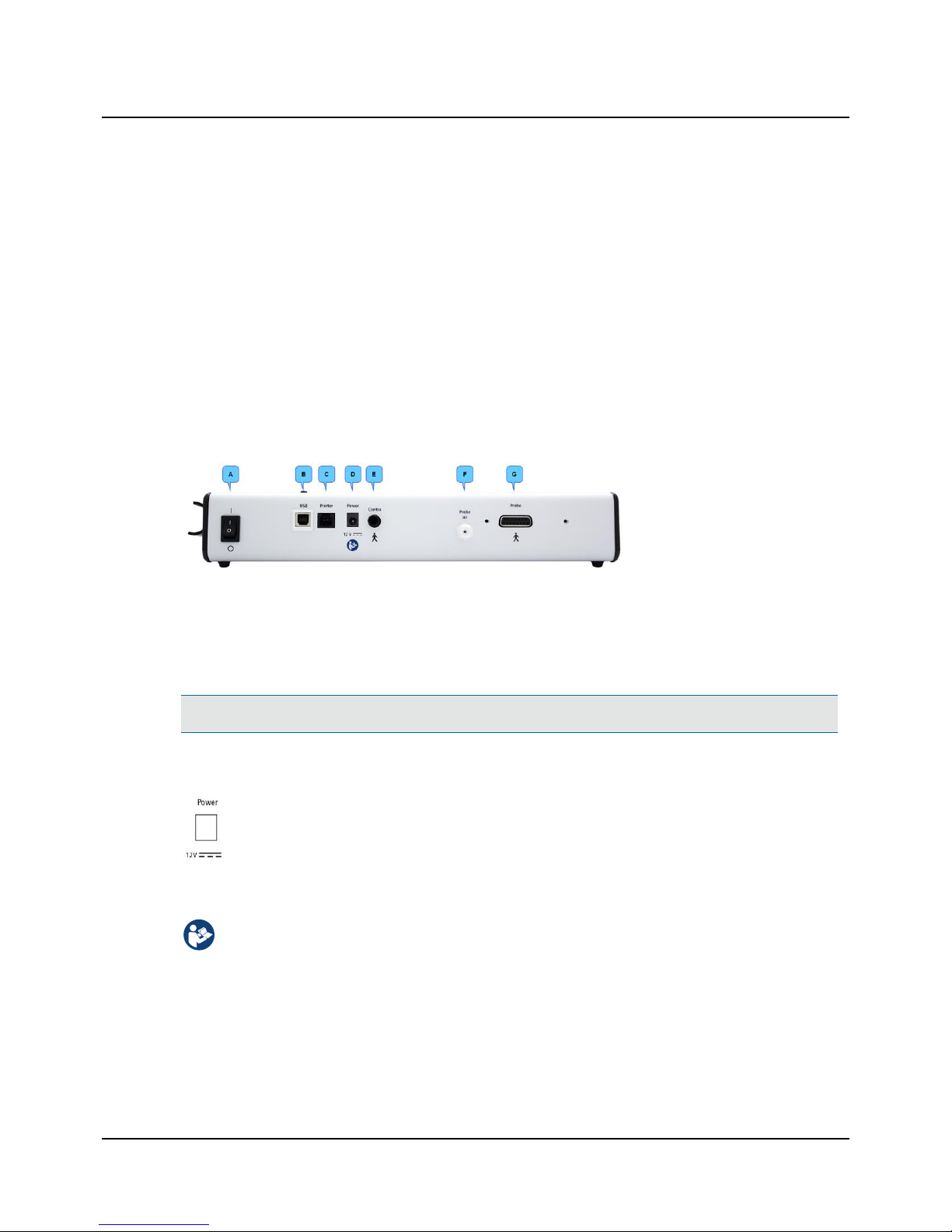
4.1 The connection panel
T830/T840
A. On/Off switch
B. PC/USB connection
C. Printer cable connection
D. External power supply
E. Contralateral phone (T840
only)
F. Probe air supply connection
G. Probe
4.2 Powering the device
The device is powered through an external power supply connected directly to the mains outlet.
Caution • Use only the power supply specified in Technical specifications ► 22.
Connecting the external power supply to the device
1. Connect the plug end of the external power supply cable to the external power supply socket on the
back of the device.
Connecting the external power supply to the mains supply
1. Connect the mains plug of the external power supply directly to an AC mains outlet.
2. If applicable, switch on the mains supply.
Switching the device on and off
1. To switch on the device, press the On/Off button on the back of the device.
– The display lights up.
2. To switch off the device, press the On/Off button.
If needed, switch off the mains supply and disconnect the power supply from the mains outlet.
7
User Guide
Inmedico A/S - T830/T840
Page 8
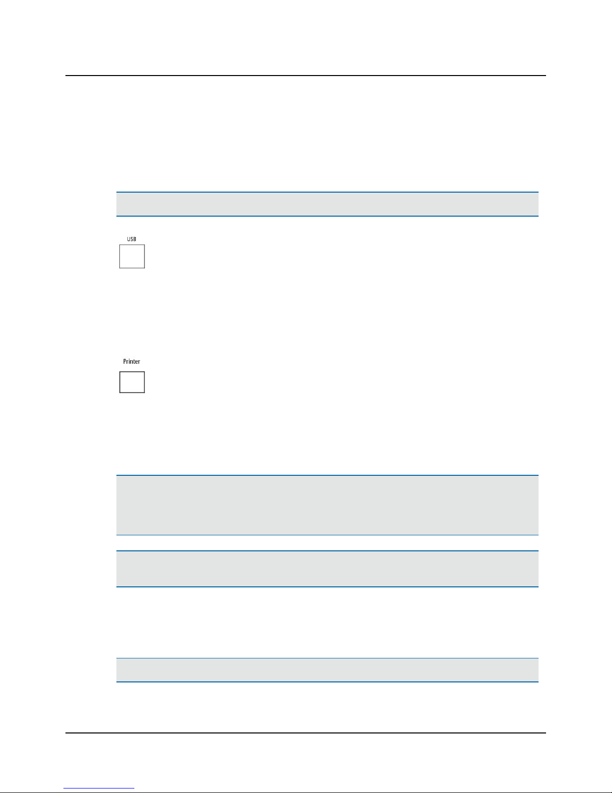
4.3 Connecting to the PC
To connect the device to the PC, you must install Oscilla® AudioConsole on the PC.
For instructions on installing AudioConsole, see the AudioConsoleUser Manual.
Caution • Use only the USB cable supplied with the device.
1. Connect the supplied USB cable from the USB socket on the back of the device to a USB socket on the
PC. The AudioConsole Windows automatically detects and installs the device.
When the device has been installed, AudioConsole detects the device and prompts you to enter the license key.
When the license key has been registered, the device is shown in the Instrument Manager in the lower left corner of the
AudioConsole screen.
4.4 Connecting the printer
1. Connect the supplied printer cable from the printer socket on the back of the device to the socket on
the printer.
5 The probe and the contralateral phone
Warning• Inspect the patient's ear. Look into the ear canal. It is strongly recommended that you perform an oto-
scopy to assess the status of the outer ear before you insert the probe. If the ear canal is blocked, this may affect the
result of the test. Clean the ear canal if needed. Make sure that there is no residual fluid in the patient's ear after
cleaning or ear wax removal.
Warning• The eartip can be used for both ears. If you suspect infection in one ear, use a clean eartip and probe tip
before you continue testing on the other ear.
Hygienic precautions
• Be sure to follow any established infection control procedures for the setting in which you are working.
• Always use clean eartips.
Warning• To prevent cross-infection, use new eartips when you test the next client.
Inmedico A/S - T830/T840
User Guide
8
Page 9
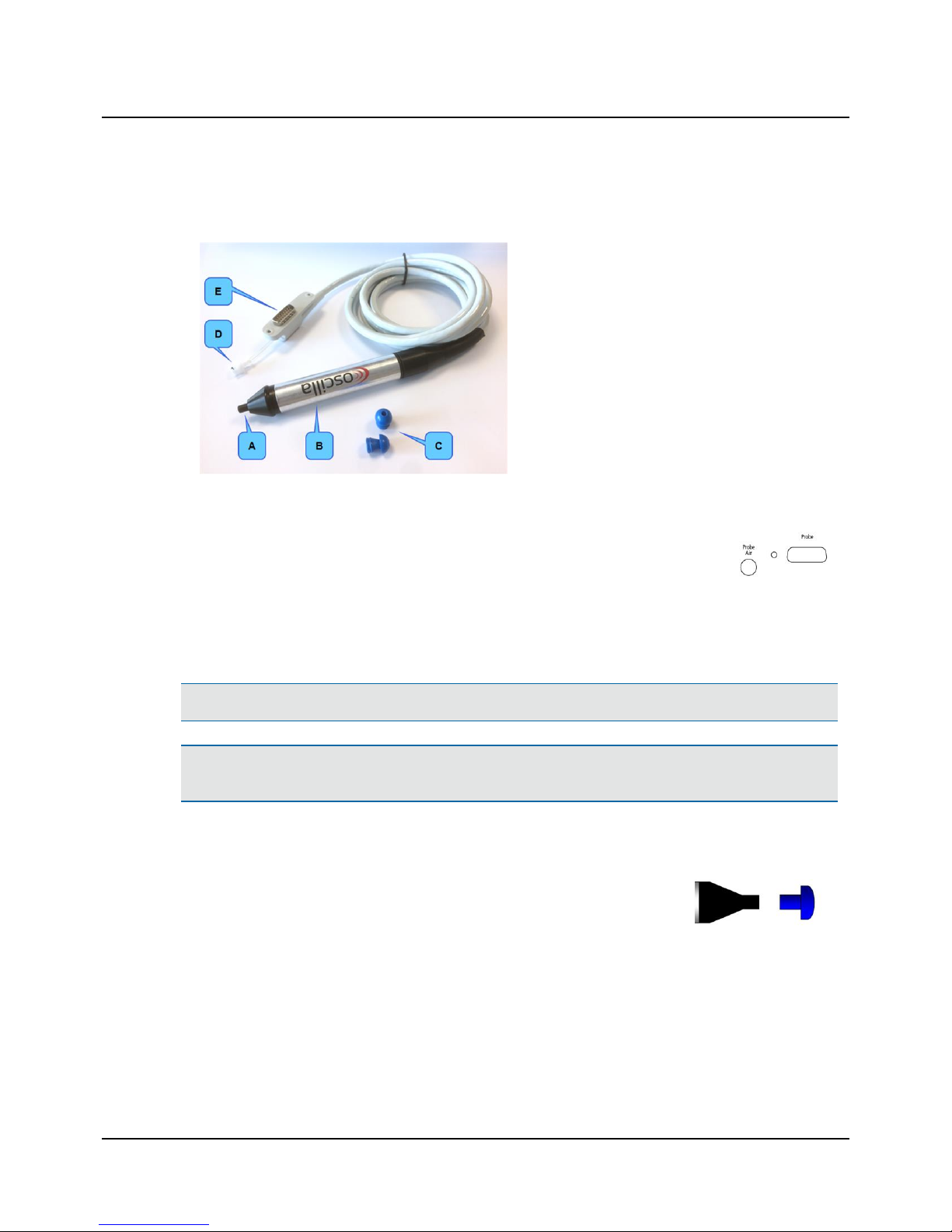
5.1 The probe
A. Probe tip
B. Probe body
C. Eartips (example)
D. Air connection plug
E. Probe connection plug
Connecting the probe
1. To connect the probe, insert the probe plug and the air connection plug into the probe socket
and air supply socket on the connection panel.
Using the probe
• Fitting the eartip on the probe ► 9
• Cleaning the probe and probe tip ► 19
Warning• Always fit an eartip on the probe before inserting it into the ear of the patient.
Warning• The eartip can be used for both ears. If you suspect infection in one ear, use a clean eartip and probe tip
before you continue testing on the other ear.
5.2 Fitting the eartip on the probe
1. Firmly push and twist the eartip onto the probe tip,
until it rests firmly against the base of the probe tip.
Removing the eartip
• To remove the eartip, grasp the stem of the eartip and pull the eartip straight off the probe tip.
9
User Guide
Inmedico A/S - T830/T840
Page 10
5.3 Fitting the probe in the patient's ear
1. Look into the ear canal. It is strongly recommended that you perform an otoscopy to assess the status of the outer ear
before you insert the probe.
2. If the ear canal is blocked, this may affect the result of the test. Clean the ear canal if needed.
Caution • The probe can be damaged if fluids enter the probe.
Warning• Never place the probe tip in the ear canal of a new patient without using a clean eartip.
Warning• The eartip can be used for both ears. If you suspect infection in one ear, use a clean eartip and probe tip
before you continue testing on the other ear.
Caution • Always use a suitably sized eartip. Using a probe with an unsuitably sized eartip or applying excessive force
may cause unnecessary discomfort to the patient.
Procedure
1. Fit the eartip on the probe.
2. To stabilize the probe and to avoid blocking the probe against the ear canal of the patient, grasp the pinna and gently
pull the pinna back and slightly away from the patient's head.
– For adults: pull the pinna upwards and back.
– For infants and children: pull the pinna downwards and back.
3. Insert the probe in the patient's ear canal while twisting the probe gently.
4. Make sure that the eartip fits well. This will minimize the risk of blocking the probe tip against the ear canal wall.
Probe status and leakage
The status indicator in the lower left corner of the device screen, or, if applicable, on the AudioConsole screen, will show
the status of the probe.
Text Description
Blocked
Indicates that probe tip is blocked (this may be caused by incorrect positioning of the probe in
the ear).
Leak
Indicates that the air seal between the probe and the ear is not tight.
5.4 The contralateral phone (T840 only)
If you wish to test for the contralateral reflex, use the contralateral phone to present the stimulus to the non-probe ear.
Inmedico A/S - T830/T840
User Guide
10
Page 11

Connecting the contralateral phone
1. To connect the phone, insert the plug end into the contralateral phone socket on the connection panel.
Push the plug firmly into the socket until it locks into the socket.
Disconnecting the contralateral phone
• To disconnect the contralateral phone, take hold of the reinforced sleeve of the plug and pull firmly until the plug is
disconnected.
Insert phone
Caution • Never insert the contralateral phone into the patient's ear without first inspecting the patient's ear canal.
Warning• The eartip can be used for both ears. If you suspect infection in one ear, use a clean eartip and probe tip
before you continue testing on the other ear.
Warning• Do not use the contralateral insert phone in an ear with discharge. Use a supra-aural phone instead.
Warning• To prevent cross-infection, use new eartips when you test the next client.
Fitting a foam tip on the insert phone
1. Fit a suitably sized foam eartip on the contralateral insert phone.
2. Before inserting the eartip in the patient's ear, compress the foam eartip to make it smaller. Insert the eartip in the
patient's ear until the outer surface of the eartip is flush with the ear canal entrance.
The eartip will expand in the ear canal within a few seconds.
Supra-aural phone
1. Fit the supra-aural phone on the patient's head so that the center of the phone is directed towards the entrance of
the ear canal.
Caution • Some ear canals may collapse and prevent the stimulus from entering the ear. In such cases either use the
insert phone or follow local recommendations.
6 Tympanometry testing using the device
The main screen
The tympanometry main screen is shown on the display when you start up the device.
11
User Guide
Inmedico A/S - T830/T840
Page 12

T830
T840
A. Online values
B. Status indicator
C. Softbutton selections
D. Tympanogram
E. Reflex table
A. On-line values
Middle ear pressure
Shows the pressure with the highest measured compliance.
Ear volume
Shows the volume of the section between the ear tip and the eardrum in ml.
Compliance
Shows the value of the compliance from the tympanogram in ml.
Tymp width
Shows the value that sums up the curve characteristics in one number.
B. Status indicator
The status indicator can display a number of messages:
Ready
Indicates that the device is ready for testing.
Blocked
Indicates that probe tip is blocked (this may be caused by incorrect positioning of
the probe in the ear).
Leak
Indicates that the air seal between the probe and the ear is not tight.
Tymp
Indicates that the tympanometric test is in process.
Inmedico A/S - T830/T840
User Guide
12
Page 13

B. Status indicator
Reflex
Indicates that a reflex test is in process.
Remove
Indicates that a test is finished and the probe can be removed from the ear.
C. Softbutton selections
Press the softbutton to toggle the selections shown above the button.
D. Tympanogram
The tympanogram shows the graph of the middle ear compliance as a function of pressure.
• The X-scale represents the pressure in daPa.
• The Y-scale represents the compliance in equivalent volume of air in ml.
E. Reflex table
The reflex table shows the ear’s reflex response to the five test tones.
• The X-scale shows the progress of the deflection curve.
• The Y-scale indicates if a change in compliance greater than 0.05 ml is detected and a reflex is considered present.
6.1 Softbutton functions
Softbuttons below the screen
Probe: Left or Probe: Right
Press this button to select the ear on which you wish to perform the test: Left or Right.
Stim: Ipsi or Stim: Contra or Stim: Ipsi/Contra (Stim: Contra or Stim: Ipsi/Contra - T840
only)
Press this button to select ipsilateral or contralateral reflex testing, or both. You can also
deselect reflex testing.
View: Ipsi, View: Contra or View: Both (View: Contra and View: Both - T840 only)
Press this button to select whether to show ipsilateral, contralateral or both measurements on the display.
Current ID
Press this button to browse between saved measurements and available storage slots in
the integrated memory. You can save up to 200 measurements.
Measurement IDs are numbered from 1 to 200. If the memory is full, you can use the Oscilla®AudioConsole software, if available, for storing more measurements.
13
User Guide
Inmedico A/S - T830/T840
Page 14

Softbuttons on the right-hand side of the screen
Print
Press this button to print the active measurement.
Settings
Press this button to enter the Settings menu. See section for an introduction to the setup
and configuration of the device.
To exit the Settings menu, press the Home softbutton.
Calibration
Press this button to calibrate the probe. For this, you will need the calibration cavities supplied with your device. When you activate calibration mode, the calibration guide is shown
on the display. Follow the steps shown to calibrate the probe.
2/1 - Shift
Press and hold this button to access more functions in the right hand side menu.
Delete
Press this button to delete the current measurement.
6.2 Setting up tympanometry testing
1. Press the Settings button to enter the Tym-
panometer settings menu.
In the Tympanometer settings menu, you can
adjust and configure a number of settings.
2. Use the up/down arrow buttons to navigate, and
press the Enter softbutton to select.
Inmedico A/S - T830/T840
User Guide
14
Page 15

Reflex levels
If needed, adjust the reflex stimulus tones for ipsilateral and contralateral reflex tests and set the
reflex sensitivity (T830 supports 500 to 3000 Hz).
– Reflex levels
Use the -/+ buttons to adjust the reflex levels
from 80 to 110 dB HL.
– Reflex sensitivity
Use the -/+ buttons to adjust the reflex sensitivity from 10 to 200 microliters. 10 is the
least sensitive, 200 is the most sensitive.
Default: 30 microliters.
Tympanometer test (T840 only):
If needed, choose between Normal mode and
Extended mode.
Normal mode
In Extended mode, the graph is scaled to allow for
showing higher curves.
Extended mode
Time and date
If needed, adjust the time and date settings of the
device.
Use the arrow buttons to navigate, and the -/+ buttons to adjust the time settings.
15
User Guide
Inmedico A/S - T830/T840
Page 16

Printer settings
Select/deselect details to be included on printouts.
Use the arrow buttons to navigate, and the checkmark button to select/deselect the details.
Language (T840 only)
If needed, change the language setting of the
device.
Use the arrow buttons navigate, and the checkmark button to select the language.
6.3 Performing a tympanometric measurement
See Fitting the eartip on the probe ► 9 and Fitting the probe in the patient's ear ► 10.
1. If needed, press the Probe softbutton to select the
ear you wish to test first.
2. When the status indicator displays the Ready mes-
sage, insert the probe into the patient’s ear.
3. When you have inserted the probe in the patient’s
ear, the test starts automatically. Test results are
shown on the display while the test is running.
4. Make sure that the eartip fits well. This will minimize the risk of blocking the probe tip against the ear canal wall.
A flat tympanogram together with an abnormally small ear canal volume indicates that the probe is blocked.
A measurement will not autostart if the ear canal volume reading is too low.
5. Make sure that you keep the probe in a steady horizontal position, and as still as possible. Even slight movements can
affect the test results.
6. Any leakage will interrupt the test. The status indicator on the screen will indicate if there is a leak.
If an air leak or blockage should occur, the status indicator will alert you by displaying the message Leak or Blocked.
If either of these messages is displayed, adjust the position of the probe slightly to continue the test. If the message
Leak or Blocked reappears, remove the probe from the patient’s ear and start a new test.
7. The status indicator shows when the test is completed by displaying the message Remove.
Inmedico A/S - T830/T840
User Guide
16
Page 17

8. If needed, press the Probe softbutton to select the other ear and repeat the test.
7 Testing using the Oscilla® AudioConsole software
With AudioConsole you can carry out measurements from the PC, save patient data in the AudioConsole patient database,
generate customized PDF reports, and export data to most patient management systems.
For a general introduction to AudioConsole please see the AudioConsole User Manual, where you will find descriptions for
operator setup, database management, reports and data import/export.
The following sections provide you with a basic description of how to operate the device from AudioConsole.
• Connecting to the PC ► 8
• Tympanometry testing using AudioConsole ► 17
8 Tympanometry testing using AudioConsole
Note•The safety intensity level cannot be exceeded in screening mode.
1. Launch AudioConsole and select or create operator and patient from the operator and patient
databases.
2. Click the New Impedance Session button.
3. Select the ear you wish to test.
4. Select the reflex test type.
5. Insert the probe in the patient’s ear.
6. The status indicator on the screen indicates when
the test is complete, and when you can remove
the probe.
Measurements are shown on the screen.
7. Click the Save button to save the measurements.
17
User Guide
Inmedico A/S - T830/T840
Page 18

Indicators, buttons and functions
Probe frequency indication.
Print out the tympanogram on the built-in device printer.
Open the Tympanometer settings menu on the device.
Delete the currently selected measurement.
Calibrate the device using the calibration cavities.
Import measurements from the device.
9 Device setup using AudioConsole
To set up the device for tympanometry testing, see Setting up tympanometry testing ► 14.
10 Service, cleaning and calibration
Warning• Under no circumstances disassemble T830/T840. Contact your supplier. Parts inside T830/T840 must only
be checked or serviced by authorized personnel.
Warning• For the sake of safety and in order not to void the warranty, service and repair of electro-medical equip-
ment should be carried out only by the equipment manufacturer or by service personnel at authorized workshops. In
case of any defects, make a detailed description of the defect(s) and contact your supplier. Do not use a defective
device.
10.1 Cleaning the device
Caution • Make sure that you comply with local infection control regulations.
Inmedico A/S - T830/T840
User Guide
18
Page 19

Caution • Use only the cleaning agents prescribed for cleaning the device.
See Recommended cleaning agents ► 19.
Frequency
We recommend that you set up a schedule for cleaning the device and accessories such as probes and/or earphones.
Prerequisites
• Before cleaning, switch off T830/T840 and disconnect it from any external power source.
• If needed, unplug the contralateral phone from the device.
Cleaning the probe tip
See Cleaning the probe and probe tip ► 19.
Disposal
There are no special requirements for the disposal of disposable articles such as eartips, i.e. they can be discarded according to local regulations.
10.1.1 Recommended cleaning agents
Caution • Use only the cleaning agents prescribed for cleaning the device.
For cleaning the device, we recommend that you only use non-alcohol-based disinfectant wipes (e.g. Audio wipe) or a
cloth dampened lightly with a recommended cleaning agent to ensure proper infection control and maximum lifetime of
the device.
The following chemical solutions are recommended:
Cabinet surface and probe
• Non-alcohol-based disinfectant wipes (e.g. Audio wipe)
• Lukewarm water with a mild detergent
Caution • If plastic parts are soaked in a cleaning agent they will deteriorate.
10.1.2 Cleaning the probe and probe tip
Although the probes are designed to be easily cleaned, care should be taken to make sure that they last a long time.
Note•Check the sound channels in the probe tip every time you have used the probe.Even small amounts of cerumen
or vernix can block the sound channels. Clean the sound channels if needed.
Note•Accurate testing is only guaranteed if you use the eartips approved specifically for the device.
19
User Guide
Inmedico A/S - T830/T840
Page 20

Ear canal debris blocking the probe tubes can lead to abnormally large ear canal volume readings, leak messages, and other
odd results.
Warning• Fit a new probe tip on the probe if you have been testing on an infected ear canal.
Cleaning the probe
• Wipe the probe with a disinfectant wipe, such as Audio-wipes, between patients.
• Wipe the cable with a disinfectant wipe, such as Audio-wipes.
• Wipe the probe home with a disinfectant wipe, such as Audio-wipes.
• Alternatively, use a damp, non-flocculent cloth with a small amount of mild detergent.
Cleaning the probe tip
Note•Always comply with local hygienic standards for disinfection.
A. Probe body
B. Probe tip
1. To remove the probe tip, hold the probe by the probe body and carefully pull off the probe tip.
Caution • Even the slightest amount of moisture may dissolve any residual cerumen and thus contaminate the sens-
itive parts in the body of the probe.
Caution • Be careful not to push or bend the small metal pipe on the probe.
2. Check to see if the sound channels of the probe tip are blocked.
Caution • Never clean the sound channels in the probe body, as this may cause damage to the probe.
3. Clean the probe tip in lukewarm water with a mild detergent.
4. Dry the probe tip thoroughly.
5. Carefully fit the probe tip back on the probe.
10.1.3 The test cavities
If a test cavity becomes contaminated, do not use it. Dispose of it and replace it with a new one.
Inmedico A/S - T830/T840
User Guide
20
Page 21

10.1.4 Replacing the internal battery
Caution • Replacing the battery should only be performed by an authorized technician.
Caution • Using another type of battery may present a risk of fire or explosion.
• Replace the internal battery only with a non-rechargeable lithium/manganese dioxide battery typeCR 2032.
10.2 Calibration
The device and the probe are delivered fully calibrated.
• The device is calibrated from the factory in dB SPL or dB HL using the stated reference equivalent thresholds. dB HL
are related to sound pressure levels. See RETSPL Table in the section Technical specifications ► 22.
Daily calibration
The probe should be calibrated daily.
See Daily calibration ► 21.
Note•If the test environment changes, for instance if there is a change in humidity or if you are going to test at a dif-
ferent altitude, make a daily calibration to verify that the system measures correctly.
Annual calibration
• The device and probe(s) must be calibrated every year by an authorized service department.
Warning• Local government rules and regulations, if applicable, should be followed at all times.
10.3 Daily calibration
To make sure that the probe is functioning correctly, it is recommended that you perform a daily calibration at the start of
each day. The probe is checked for occlusion and leakage.
Caution • Always clean and disinfect the probe tip before you insert it into a test cavity.
Note•If the test environment changes, for instance if there is an increase in humidity or if you are going to test at a
different altitude, make a daily calibration to verify that the system measures correctly.
1. Make sure that the probe tip has been cleaned and disinfected, before you place it in the test cavity. This is to make
sure that the probe tip does not influence the probe test, and that the test cavity is not contaminated.
21
User Guide
Inmedico A/S - T830/T840
Page 22

2. Fit an eartip, preferably 16 mm, on the probe tip.
3. Press the Calibration button to select the calibration function.
When you activate calibration mode, the calibration guide is shown on the display.
4. Follow the steps shown to calibrate the probe.
5. Place the probe in the cavity as shown on the display.
6. Press the Calibration button to start the calibration.
7. Hold the probe steady for a short while and press 'Next'.
Values for volume, level and pressure are shown.
If the probe calibration result is successful, a checkmark is shown.
If an error occurs during calibration, place the probe in the relevant cavity and
press the Restart button.
8. Press the Finish button to exit the calibration function.
If there is a probe error
In case of a probe error, the probe may be occluded or faulty.
• If the probe is occluded, clean the probe tip.
• If the probe is faulty, contact an authorized service department for repair.
11 Technical specifications
Type identification
T830/T840 is type 1100 from Inmedico A/S
Standards
Safety: IEC 60601-1, UL 2601-1, CAN/CSA - C22.2 NO 601.1-90
ANSI/AAMI ES60601-1 + AMD 1, CAN/CSA-C22.2 No. 60601-1
EMC: EN 60601-1-2:2007
Impedance/Admittance: IEC 60645-5: 2004, Type 2
Power supply: Class II externally powered supply
Inmedico A/S - T830/T840
User Guide
22
Page 23

Essential performance
The device has no essential performance as defined by IEC 60601-1:2005+AMD1:2012.
Classification: Group 1, class A IEC 60601-1-2:2007
Type of protection against electric shock: Class II equipment
Degree of protection against electric shock: Type B applied part
Degree of protection against liquid penetration: IPXO
Mode of operation: Continuous operation
Tympanometer
Test frequency: 226 Hz
Frequency accuracy: ± 1%
Test level: 85 dB SPL in 2 ml ± 3 dB. Level may be altered in smaller or larger ear canals.
Pressure: -300 to +200 daPa
THD: < 1% in 2 ml
Measurement range: 0.1 to 6.0 ml
Rate of pressure change: 350 daPa/s in 2 ml
Tympanometry accuracy description
Min. TW, 5% error: 38 daPa
Min. TW, 10% error: 31 daPa
Min. SA, 5% error: 31 daPa
Min. SA, 10% error: 23 daPa
Reflex measurements
Pure tone signals: 500 Hz, 1 kHz, 2kHz, 3kHz, 4kHz ± 2%
Test method: Ipsilateral and contralateral (contralateral: T840 only)
Probe level range: 80 dB HL to 110 dB HL in 2 ml ± 3 dB. No artifacts should be expected at any
level.
THD: < 2.5% in 2 ml for TDH-39 and < 5% in 2 ml for insert phones
Step size: 5 dB
Temporal characteristics
Rise/fall time: 50 ms
Stimulus On time: 460 ms
Stimulus Off time: 860 ms
On-Off ratio: 70 dB (for stimulus level > 95 dB HL)
A weighted SPL in Off: < 25 dB
23
User Guide
Inmedico A/S - T830/T840
Page 24

RETSPL table
Hz TDH-39
IEC 60318-3/NBS 9A
from ANSI/ASA S3.6-2010, Table 5
Insert phones/
IPSI probe
from ANSI/ASA S3.6-2010, Table 7
500 11.5 5.5
1 k 7 0
2 k 9 3
3 k 10 3.5
4 k 9.5 5.5
Power supply
Friwo FOX18 FW8001M 100-240 VAC/12 VDC, 50-60 Hz
USB port connector
For PC connection
Warm-up time
< 10 minutes
Physical attributes
Dimensions (WxDxH): 225 x 180 x 55 mm (8.9 x 7.0 x 2.2 in)
Weight: 1.3 kg (2.9 lb)
Operating environment
Ambient temperature: +15 to +35°C (+59 to 95°F)
Relative humidity: 30% to 90% (non-condensing)
Air pressure: 700 hPa to 1060 hPa
Transport and storage
Ambient temperature: -20°C (-4°F) or +60°C (140°F)
Relative humidity: 90% or less (non-condensing)
Air pressure: 700 hPa to 1060 hPa
Disposal
T830/T840 can be disposed of as normal electronic waste, according to WEEE and local regulations.
Inmedico A/S - T830/T840
User Guide
24
Page 25

PC system requirements for Oscilla® AudioConsole (optional)
For system requirements, please see the Oscilla®AudioConsoleUser Manual.
11.1 Accessories
The accessories listed depend on the configuration of the device supplied.
• Oscilla® Immittance Probe
• Eartips for Tympanometry
• Contralateral phone, Wilfan headband fitted with TDH-39 earphone or Inmedico A/S insert phone (T830/T840 only)
• Oscilla® calibration cavity set
• Oscilla® AudioConsole SW on memory stick, optional
• User Guide
• USB connection cable, device to PC, optional
• External printer with connection cable, CUSTOM Q3X, optional
• Carrying bag, optional
• Calibration certificate
11.2 Notes on EMC (Electromagnetic Compatibility)
• T830/T840 is part of a medical electrical system and is thus subject to special safety precautions. For this reason, the
installation and operating instructions provided in this document should be followed closely.
• Portable and mobile high-frequency communication devices, such as mobile phones, may interfere with the functioning of T830/T840.
Guidance and manufacturer'sdeclaration - electromagnetic emissions for all equipment and systems
T830/T840 isintended fo r usein the electromagnetic environment specified below. The user of T830/T840shou ld ensureth at it isu sed in such an environment.
Emissions test Compliance Electromagnetic environment - guidance
RF emissions
CISPR 11
Group 1 T830/T840uses RF energy only for its internalfunction. Therefore, itsRF emissions arevery low
and are not likely to cause any interference in nearby electronic equipment.
RF emissions
CISPR 11
ClassA Class A coversd evices for usagein all establishments other than domestic and that are not d ir-
ectly connected to a lowvo ltage power supply network, which supplies domestic environment.
Warning: This equipment/system isintended for useby healthcarep rofessionalso nly.
Harmonic emissions IEC
61000-3-2
Not app licable
Voltage fluctuations/flicker
emissions IEC 61000-3-3
Not app licable
25
User Guide
Inmedico A/S - T830/T840
Page 26

Guidance and manufacturer'sdeclaration - electromagnetic immunityfor all equipment and systems
T830/T840 isintended fo r usein the electromagnetic environment specified below. The user of T830/T840shou ld ensureth at it isu sed in such an environment.
Immunitytest IEC 60601
test level
Compliance level Electromagnetic environment - guidance
Electrostatic discharge (ESD)
IEC 61000-4-2
+/- 6 kV co ntact
+/- 8 kV air
+/- 6 kV co ntact
+/- 8 kV air
Floors should b ewoo d, concrete or ceramic tile.If floors
are covered with synthetic material, the relative humid-
ity should b e at least 30 %.
Electrical fast transient/burst
IEC 61000-4-4
+/- 2 kV fo r power supp ly lines
+/- 1 kV fo r input/outpu t lines
+/- 2 kV fo r power supp ly lines
+/- 1 kV fo r input/outpu t lines
Mains power quality should be that of a typical com-
mercialor hospital environment.
Surge IEC 61000-4-5 +/- 1 kV line(s) to line(s)
+/- 2 kV line(s) to earth
+/- 1 kV line(s) to line(s)
+/- 2 kV line(s) to earth
Mains power quality should be that of a typical com-
mercialor hospital environment.
Voltage dips,short inter-
ruptionsand voltage vari-
ations on p ower supply inp ut
lines IEC 61000-4-11
<5%UT(>95% dip in UT) fo r 0.5
cycle
40% U T(60 % dip in UT) fo r 5
cycles
70% UT(30 % dip in UT) fo r 25
cycles
<5%UT(>95% dip in UT) fo r 5s
<5%UT(>95% dip in UT) fo r 0.5
cycle
40% U T(60 % dip in UT) fo r 5
cycles
70% UT(30 % dip in UT) fo r 25
cycles
<5%UT(>95% dip in UT) fo r 5s
Mains power quality should be that of a typical com-
mercialor hospital environment. If the userof the
T830/T840 requires continued operation during po wer
mains interruptions, it is recommended that the
T830/T840 be powered from an uninterruptible power
supply or a b attery.
Power frequency
(50/60Hz) magnetic field
IEC 61000-4-8
3 A/m 3 A/m Power frequency magnetic fields should b eat levelschar-
acteristic of a typ ical location in a typical commercial or
hospital environment.
UTis the AC mains voltageprior to application o f the test level.
Guidance and manufacturer'sdeclaration - electromagnetic immunity- for equipment and systemsthat are NOT life-supporting
T830/T840 isintended fo r usein the electromagnetic environment specified below. The user of T830/T840shou ld ensureth at it isu sed in such an environment.
Immunity test IEC 60601
test level
Compliance level Electromagnetic environment - guidance
Inmedico A/S - T830/T840
User Guide
26
Page 27

Cond ucted RF
IEC 61000-4-6
3 Vrms
150 kHzto 80MHz
3 Vrms
150 kHzto 80MHz
Portableand mobile RF communications equipment
should b eused no closer to any part of T830/T840,
including cables, than the recommended separation dis-
tance calculated from the equation applicable to thefre-
quency of the transmitter.
Recommended separation distance:
d = 1.2
d = 1.2 fo r 80 MHz to 800 MHz
d = 2.3 fo r 80 MHz to 2.5GHz,
whereP is the maximum outpu t power rating of the
transmitter in watts (W) accordin g to the transmitter
manufacturer and d is the recommended separation dis-
tance in metres(m).
Field strengths from fixed RF transmitters, asd eterm-
ined by an electromagnetic sitesurvey,ashould b eless
than the co mpliance level in each frequency range.
b
Interference may occur in the vicinity of equipment
marked with th issymbol:
Radiated RF
IEC 61000-4-3
3 V/m
80MHz to 2.5GHz
3 V/m
80MHz to 2.5GHz
Note 1: At 80MHzand 800MHzth eseparation distance for the higher frequency rangeapplies.
Note 2: These guidelines may not applyin all situations. Electromagnetic propagation is affected by absorption and reflection from structures, objects and
people.
a. Field strengths from fixed transmitters, such as basestations for radio ( cellular/cordless) telepho nesand land mob ileradios, amateur radio, AMand FM radio
broadcast and TV bro adcast canno t be predicted theoretically with accuracy. To assessth eelectromagnetic environment d ue to fixed RF transmitters, an
electromagnetic sitesurvey should be considered. If the measured field strength in the location in which T830/T840is used exceedsthe applicable RF com-
pliance level above, the T830/T840 shou ld be observed to verify normal operation. If abnormal performance is observed, additional measuresmight ben eces-
sary, such as reorienting o r relocating T830/T840.
b. Over the frequency range150kHz to 80 MHz, field strengths should be less than 3 V/m.
Recommended separation distances between po rtable and mobile RF communications equipment and T830/T840
The T830/T840is intended f or use in an electromagnetic environment in which radiated RF d isturbances are controlled. The customer or the user of the
T830/T840 can help prevent electromagnetic interference by maintaining a minimum distance between p ortableand mobile RF communications equipment
(transmitters) and the T830/T840asrecommended b elow, according to the maximum ou tput power of th ecommunications equipment.
Rated maximum output power of
transmitter
W
Separation distance according to frequency of transmitter
m
150 kHzto 80MHz
d = 1.2
80MHz to 800 MHz
d = 1.2
800 MHz to 2.5GHz
d = 2.3
0.01 0.12 0.12 0.23
0.1 0.38 0.38 0.73
1 1.2 1.2 2.3
27
User Guide
Inmedico A/S - T830/T840
Page 28

10 3.8 3.8 7.3
100 12 12 23
For transmitters rated at a maximum ou tput power not listed above, the recommended separation d istance d in meters (m) can b eestimated using the equa-
tion app licableto the frequency o f the transmitter, where P is the maximum outpu t power rating of the transmitter in watts( W) according to the transmitter
manufacturer.
Note 1: At 80MHzand 800MHzth eseparation distance for the higher frequency rangeapplies.
Note 2: These guidelines may not applyin all situations. Electromagnetic propagation is affected by absorption and reflection from structures, objects and
people.
12 Standards and warnings
This manual contains information and warnings, which must be followed to ensure the safe performance of the devices and
software covered by this manual. Local government rules and regulations, if applicable, should also be followed at all times.
12.1 Definition of symbols
T830/T840
Electronic equipment covered by the Directive 2002/96/EC on waste electrical and electronic equipment
(WEEE).
All electrical and electronic products, batteries, and accumulators must be taken to separate collection at
the end of their working life. This requirement applies in the European Union. Do not dispose of these
products as unsorted municipal waste.
You can return your device and accessories to Inmedico A/S, or to any Inmedico A/S supplier. You can also
contact your local authorities for advice on disposal.
Consult user manual for warnings and cautions.
Consult user manual for warnings and cautions.
Complies with Type B requirements of IEC60601-1.
Complies with Medical Devices Directive 93/42/EEC.
Complies with RoHS Directive (2011/65/EC).
Inmedico A/S - T830/T840
User Guide
28
Page 29

MEDICAL - General Medical Equipment as to electrical shock, fire and mechanical hazards only in accordance with UL 60601-1, first edition, 2003 CAN/CSA-22.2 No. 601.1-M90.
OR
MEDICAL - General Medical Equipment as to electrical shock, fire and mechanical hazards only in accordance with ANSI/AAMI ES60601-1 (2005) + AMD 1 (2012), IEC 60601-1-6, CAN/CSA-C22.2 No. 60601-1
(2014) and CAN/CSA-C22.2 No. 60601-1-6 (2011).
In France, it is only permitted to use the device indoors.
This device complies with part 15 of the FCC rules. Operation is subject to the following two conditions:
• This device must not cause harmful interference.
• This device must accept any interference received, including interference that may cause undesired
operation.
The term”IC” before the certification/registration number signifies that the Industry Canada technical specifications were met.
Serial number
Catalog/product number
Suitable for direct current only.
12.2 Warning notes
This manual contains information and warnings, which must be followed to ensure the safe performance of the devices and
software covered by this manual. Local government rules and regulations, if applicable, should also be followed at all times.
1. This class of equipment is allowed in domestic establishments when used under the jurisdiction of a health care professional.
2. T830/T840 is intended for diagnostic and clinical use by audiologists and other trained health care professionals in testing the hearing of their patients.
3. If you suspect infection in one ear, exchange the eartip and use a clean probe tip before you continue testing on the
other ear.
4. To prevent cross-infection, use new eartips when you test the next client.
5. Accidental damage and incorrect handling can have a negative effect on the functionality of the device. Contact your
supplier for advice.
6. For the sake of safety and in order not to void the warranty, service and repair of electro-medical equipment should
be carried out only by the equipment manufacturer or by service personnel at authorized workshops. In case of any
defects, make a detailed description of the defect(s) and contact your supplier. Do not use a defective device.
7. It is recommended to install the unit in an environment that minimizes the amount of static electricity. For example,
anti-static carpeting is recommended.
8. We recommend that the device should not be stacked with other equipment or placed in a poorly ventilated space as
this may affect the performance of the device. If it is stacked or placed adjacent to other equipment, make sure that
the operation of the device is not affected.
29
User Guide
Inmedico A/S - T830/T840
Page 30

9. Do not store or operate the device at temperatures and humidity exceeding those stated in the Technical Specifications, Transport and storage.
10. Keep the unit away from liquids. Do not allow moisture inside the unit. Moisture inside the unit can damage the
instrument and it may result in a risk of electrical shock to the user or patient.
11. Do not use the instrument in the presence of flammable agents (gases) or in an oxygen-rich environment.
12. No parts may be eaten, burnt, or in any way used for purposes other than the applications defined in the Intended Use
section of this manual.
13. Choking hazard! Do not leave eartips unsupervised within the reach of children.
14. The device and any device to be connected which has its own power supply should be turned off before any connections are established. To disconnect the device from the mains supply, pull the mains plug out of the wall mains
outlet. Do not position the unit so that it is difficult to pull the mains plug out of the wall mains.
15. For safety reasons and due to effects on EMC, accessories connected to the equipment's outlet fittings must be
identical to the type supplied with the system.
16. It is recommended that an annual calibration be performed on accessories containing transducers. Furthermore, it is
recommended that calibration be performed if the equipment has suffered any potential damage (e.g. headphones,
contraphones, probes dropped on the floor).
Note that calibration has been performed only on the transducers supplied! If you wish to use any other transducer for
testing with the device, please contact your local distributor first.
17. Disposable accessories, such as eartips, should not be reused and must be replaced between patients to prevent crossinfection.
18. Unwanted noise may occur if the instrument is exposed to a strong radio field. Such noise may interfere with the process of recording correct measurements. Many types of electrical devices, e.g. mobile telephones, may generate radio
fields. We recommend that the use of such devices in the vicinity of this instrument be restricted as much as possible.
Likewise, we recommend that the instrument is not used in the vicinity of devices sensitive to electromagnetic fields.
19. Changes or modifications not expressly approved by the manufacturer could void the user's authority to operate the
equipment.
20. The device and power supply can be disposed of as normal electronic waste, according to local regulations.
21. Use only the specified power supply.
See Technical Specifications, Power supply.
When assembling an electro-medical system, the person carrying out the assembly must take into account
that other connected equipment which does not comply with the same safety and EMC requirements as this
product (e.g., cables, PC and/or printer) may lead to a reduction in the overall safety level or EMC compliance level of the system. The equipment must comply with IEC 60950.
When selecting accessories connected to the device, the following points must be considered:
• Use of connected equipment in a patient environment.
• Proof that connected equipment has been tested in accordance with IEC 60601-1 (3rd), AAMI ES60601-1
and CAN/CSA-C22.2 NO. 60601-1-08-CAN/CSA.
Do not touch the output DC plug of the power supply or connectors of the device or connected devices and
the patient at the same time.
22. To comply with IEC 60601-1(3rd) computer and printer must be placed out of reach of the client, i.e. not closer than
approx. 1.5 meters/5 ft.
Inmedico A/S - T830/T840
User Guide
30
Page 31

13 Other references
For instructions on installing Oscilla® AudioConsole, see the Oscilla® AudioConsoleManual.
14 Manufacturer
Inmedico A/S
Johann Gutenbergs Vej 3, DK-8200 Aarhus N
Denmark
(+45 86 74 26 22
www.oscillahearing.com
support@oscillahearing.com
14.1 Responsibility of the manufacturer
The manufacturer is to be considered responsible for effects on safety, reliability, and performance of the equipment only
if:
• All assembly operations, extensions, re-adjustments, modifications or repairs are carried out by the equipment manufacturer or personnel authorized by the manufacturer.
• The electrical installation to which the equipment is connected complies with EN/IEC requirements.
• The equipment is used in accordance with the instructions for use.
The manufacturer reserves the right to disclaim all responsibility for the operating safety, reliability and performance of
equipment serviced or repaired by other parties.
31
User Guide
Inmedico A/S - T830/T840
Page 32

14 Manufacturer
Inmedico A/S - T830/T840
32
 Loading...