

Osburn Stoves by SB I HYBRID 35 User Manual
MODEL HYBRID-35
FREESTANDING & FIREPLACE INSERT
OWNER’S MANUAL
• Warning: If your appliance is not properly installed, a house fire may result. For your safety, follow the
installation directions. Contact local building or fire officials about restrictions and installation inspection
requirements in your area.
• Please read this entire manual before installation and use of this pellet fuel-burning room heater. Failure
to follow these instructions could result in property damage, bodily injury, or even death.
• Save these instructions.
• Some surfaces become hot at higher feeding rates. To prevent potential burns, avoid contact with those
areas.
Professional installation is highly recommended
Manufactured by:
Stove Builder International Inc.
Quebec City (Quebec)
CANADA
45260

INTRODUCTION
Thank you for purchasing the HYBRID-35 pellet stove & insert. You are now prepared to burn wood in
the most efficient, convenient way possible. To achieve the safest, most efficient and most enjoyable
performance from your stove, you must do three things: 1) Install it properly; 2) Operate it correctly;
and 3) Maintain it regularly. The purpose of this manual is to help you do all three.
PLEASE read this entire manual before installation and use of this pellet fuel-burning room
heater. Failure to follow these instructions could result in property damage, bodily injury or
even death.
Keep this manual handy for future reference.
Your HYBRID-35 has been independently tested to ASTM E1509-04 Standard Specification for room
heaters, pellet fuel burning type 1 and the HYBRID-35 insert has been independently tested to ASTM
E1509-04 Standard Specification for room heaters, pellet fuel burning type 1, UL 1482-1998 Standard
for solid fuel room heaters and ULC-S628-93 Standard for fireplace inserts.
This pellet stove, when installed, must be electrically grounded in accordance with local codes, or in
the absence of local codes, with the National Electrical Code, ANSI/NFPA 70 and
This appliance is designed for use with pelletized wood only. Do not burn coal of any type in this
appliance. It is designed for residential installation according to current national and local building
codes as a freestanding or insert room heater. It is also approved as a mobile home heater which is
designed for connection to an outside combustion air source.
The stove will not operate using natural draft or without a power source for the blowers and fuel feed
system.
This stove is designed to provide the optimum proportions of fuel and air to the fire in order to burn
free of smoke and soot. Any blockage of the air supply to or from the stove will seriously degrade its
performance and will be evidenced by a smoking exhaust and a sooting window. For best operation,
the ash content of the pellet fuel should be less than 1% and the calorific value approximately 8,200
BTU/LB. Avoid burning high ash content fuels because this will rapidly fill up the burn pot and
eventually cut off the combustion air supply.
The HYBRID-35 should not be used for commercial or industrial applications since operational control
is often not well managed in these settings
CSA-C22.1.
REGISTER YOU WARRANTY ONLINE
To receive full warranty coverage, you will need to show evidence
of the date you purchased your unit. Keep your sales invoice.
We also recommend that you register your warranty online at
www.osburn-mfg.com/ Registering your warranty online will
help us track rapidly the information we need on your unit.
2
SAFETY PRECAUTIONS
• Do not operate your stove if you
smell smoke coming from it. Turn it off,
monitor it, and call your dealer. DO NOT
UNPLUG IT
• Never use gasoline, gasoline-type
lantern fuel, kerosene, charcoal lighter fluid, or
similar liquids to start or “freshen up” a fire in
this stove. Keep all such liquids well away from
the stove while in use.
• Never block free airflow through the
open vents of the stove.
• Never try to repair or replace any
part of the stove unless instructions are given
in this manual. All other work should be done
by a trained technician.
• The stove will not operate during a
power outage. If an outage does occur, check
the stove for smoke spillage and open a
window if any smoke spills into the room.
• Disconnect the power cord before
performing any maintenance or repairs on the
stove.
NOTE: Turning the stove “off” does not
disconnect all power from the stove.
• Do not unplug the stove if you
suspect a malfunction. Turn the stove off,
inspect it, and call your dealer.
• Keep foreign objects out of the hopper.
• Do not throw this manual away. This
manual has important operating and maintenance
instructions that you will need at a later time.
Always follow the instructions in this manual.
• Do not place clothing or other
flammable items on or near the stove.
• The viewing door must be closed and
latched during operation.
• Do not operate the stove if the flame
becomes dark and sooty or if the burnpot overfills
with pellets. Turn the stove off, inspect it, and call
your dealer.
• Do not touch the hot surfaces of the
heater. Educate all children of the danger of a
high temperature stove. Young children should be
supervised when they are in the same room as
the stove.
• High ambient temperature in summer
time may cause the heat sensors on the stove to
activate the blowers, disconnect the stove when
not used for extended periods.
• Contact your local building officials to
obtain a permit and information on any
installation restrictions or inspection
requirements in your area. Notify your
insurance company.
• This unit must be properly installed to
prevent the possibility of a house fire. The
instructions must be strictly adhered to. Do not
use makeshift methods or compromise in the
installation.
• Allow the stove to cool before
carrying out any maintenance or cleaning.
Ashes must be disposed or stored in a metal
container with a tight lid and placed on a non
combustible surface well away from the home
structure.
• This stove must be connected to a
standard 120 V., 60 Hz grounded electrical
outlet. Do not use an adapter plug or sever the
grounding plug. Do not route the electrical cord
underneath, in front of, or over the stove.
• The exhaust system should be
checked, at least twice a year for any build up
of soot or creosote.
• The exhaust system must be
completely airtight and properly installed. The
pellet vent joints must be sealed with RTV 500°F.
(260°C.) silicone sealant, and with UL-181-AP foil
tape.
• Your stove requires maintenance and
cleaning. Failure to maintain your stove may lead
to smoke spillage in your home.
• This stove is designed and approved for
pelletized wood fuel only. Any other type of fuel
burned in this heater will void the warranty.
• When installed in a mobile home, the
stove must be bolted to the floor, have outside air,
and NOT BE INSTALLED IN A BEDROOM (Per
H.U.D. requirements). Check with local building
officials.
• Stove Builder International Inc.
grants no warranty, implied or stated, for the
installation or maintenance of your stove, and
assumes no responsibility of any
consequential damage(s).
3

TABLE OF CONTENTS
INTRODUCTION..................................................................................................................................................................... 2
SAFETY PRECAUTIONS ....................................................................................................................................................... 3
TABLE OF CONTENTS.......................................................................................................................................................... 4
FREESTANDING INSTALLATION......................................................................................................................................... 6
HYBRID-35 FREESTANDING PELLET STOVE ............................................................................................6
PREPARATION ..................................................................................................................................................6
CLEARANCES ...................................................................................................................................................6
COMBUSTION AIR SUPPLY ...........................................................................................................................7
WHEN OUTSIDE AIR IS NOT USED ..............................................................................................................7
VENTING............................................................................................................................................................7
STOVE ASSEMBLY ..........................................................................................................................................8
EQUIVALENT VENT LENGHT (EVL) ..........................................................................................................10
INSTALLATION CONFIGURATIONS ..........................................................................................................10
HORIZONTALLY THROUGH WALL .......................................................................................................10
VERTICALLY WITH NEW CHIMNEY SYSTEM.....................................................................................11
VERTICALLY INTO EXISTING CHIMNEY SYSTEM ............................................................................11
VERTICALLY INTO EXISTING MASONRY FIREPLACE .....................................................................12
INSTALLATION THROUGH SIDE OF MASONRY CHIMNEY .............................................................12
INSERT INSTALLATION...................................................................................................................................................... 13
INSERT INTO EXISTING MASONRY FIREPLACE ....................................................................................13
FACEPLATE ASSEMBLY...............................................................................................................................14
CLEARANCES .................................................................................................................................................17
DOOR OVERLAY INSTALLATION ..............................................................................................................17
OPERATION ......................................................................................................................................................................... 18
PROPER FUEL..................................................................................................................................................18
PRE-START-UP CHECK .................................................................................................................................18
BUILDING A FIRE...........................................................................................................................................18
LIGHTING PROCEDURE................................................................................................................................18
UNIT CONTROLS ............................................................................................................................................19
MODE BUTTON...........................................................................................................................................19
FUEL FEED SWITCH ..................................................................................................................................19
NOISE REDUCER ........................................................................................................................................19
HEAT LEVEL ...............................................................................................................................................19
RESET ...........................................................................................................................................................19
OPENING DOOR..............................................................................................................................................19
CONVECTION BLOWERS (ROOM AIR FANS)...........................................................................................19
COMBEXtm........................................................................................................................................................20
IF THE STOVE RUNS OUT OF PELLETS.....................................................................................................20
REFUELING .....................................................................................................................................................20
SHUTDOWN PROCEDURE ............................................................................................................................21
SAFETY FEATURES .......................................................................................................................................21
DAMPER OPERATION ...................................................................................................................................21
OPERATING THE STOVE USING A THERMOSTAT .................................................................................22
THERMOSTAT INSTALLATION...................................................................................................................22
MODES..............................................................................................................................................................22
OPERATING SAFETY PRECAUTIONS .............................................................................................................................. 23
MAINTENANCE .................................................................................................................................................................... 24
ASH REMOVAL ...............................................................................................................................................24
ASH DISPOSAL................................................................................................................................................24
4

VACCUM USE..................................................................................................................................................25
CLEANING .......................................................................................................................................................25
BLOWERS AND PRESSURE SWITCH PROBE ............................................................................................26
CHIMNEY CLEANING....................................................................................................................................26
RECOMMENDED MAINTENANCE SCHEDULE ........................................................................................26
REMOVAL AND REPLACEMENT OF DOOR GLASS ................................................................................26
TROUBLESHOOTING.......................................................................................................................................................... 27
STOVE SHUTS OFF AND SHOWS ERROR CODE “P” ...............................................................................27
STOVE SHUTS OFF AND SHOWS ERROR CODE “E” ...............................................................................28
STOVE FEEDS PELLETS, BUT WILL NOT IGNITE AND SHOWS ERROR CODE “L” .........................29
STOVE FEEDS PELLETS, BUT WILL NOT IGNITE AND SHOWS ERROR CODE “I”...........................29
STOVE STOPS FEEDING PELLETS AND SHOWS ERROR CODE “O”...................................................29
STOVE STOPS FEEDING PELLETS AND SHOWS ERROR CODE “H”...................................................30
STOVE STOPS FEEDING PELLETS AND SHOWS ERROR CODE “d”....................................................30
SMOKE SMELL COMING BACK INTO THE HOME ..................................................................................30
AUGER MOTOR STOPS FEEDING PELLETS AND COMES BACK ON ..................................................30
GLASS SOOTS UP VERY FAST....................................................................................................................31
FLAME IS LAZY, DARK, AND HAS BLACK TIPS .....................................................................................31
AFTER STOVE HAS BEEN ON FOR A WHILE, THE BURNPOT OVERFILLS .......................................31
ERROR CODES ................................................................................................................................................31
SMOKE SMELL OR SOOT BUILD-UP ..........................................................................................................31
ELECTRICAL DIAGRAM ..................................................................................................................................................... 32
ELECTRIC SHOCK ..........................................................................................................................................32
REPLACEMENT PARTS...................................................................................................................................................... 33
OSBURN LIMITED LIFETIME WARRANTY........................................................................................................................ 34
5

FREESTANDING INSTALLATION
HYBRID-35 FREESTANDING PELLET STOVE
Width: 22 1/2”
Height: 29”
Depth: 24 1/2”
Weight: 195 lbs.
Flue size: 3” or 4”
Hopper Capacity: Up to 35 lbs.
(This can vary slightly depending on pellet size, length, and diameter)
EPA status: exempt
Burn rate: 1 lb. to 4.0 lbs. per hour
BTU range: 8,200 to 35000
Electrical consumption: 3.5 Amps lighting cycle
2.5 Amps. continuous duty
Control board fuses: Main: 7.5A-250V fastblow
Igniter: 5A-250V fastblow
Electrical requirement: 120VAC 15A
Approved installations: mobile home, conventional
PREPARATION
Factory packaging must be removed, and some minor assembly work is
required prior to installation:
• The door overlay must be installed on the door frame;
• The louver kit must be installed in front of the heat exchanger.
NOTE: Normally, your dealer will perform these functions.
To remove ashes, use the ash pan or a vacuum cleaner. If you want to
use the ash pan, you will have to remove the plate located at the right side
of the burn pot.
1- Remove the three screws
2- Remove the plate
3- Put the three screws back
4- Use the ash dump cap provided with the stove
BACK WALL
2" *
6"
SIDE WALL
3"
Figure 1
Back wall installation
ADJACENT WALL
2"
3"
ADJACENT WALL
3"
2"
CLEARANCES
The HYBRID-35 has been tested and listed for installation in regular and
mobile homes.(refer figure 1 & 2)
FLOOR PROTECTION: minimum 6” in the front and 6” on each side. The
stove must be placed on a continuous (grouted joints) non-combustible
material such as ceramic tile, cement board, brick, 3/8” millboard or
equivalent, or other approved or listed material suited for floor protection.
NOTE: ceramic tile, or any tile, must be laid on a continuous non
combustible sheet to prevent the possibility of embers falling through to the
combustible floor if cracks or separation should occur in the finished
surface, this also applies to floor protection for Built-in raised hearths.
Check local codes for approved alternatives.
Clearances are measured from the sides, back and face (door opening) or
stove body (refer to fig. 3).
DO NOT USE MAKESHIFT MATERIALS OR COMPROMISES IN THE
INSTALLATION OF THIS UNIT.
INSTALL VENT WITH CLEARANCES SPECIFIED BY THE VENT
MANUFACTURER.
Figure 2
Corner installation
6"
Figure 3
Floor protection
6"
6"
6
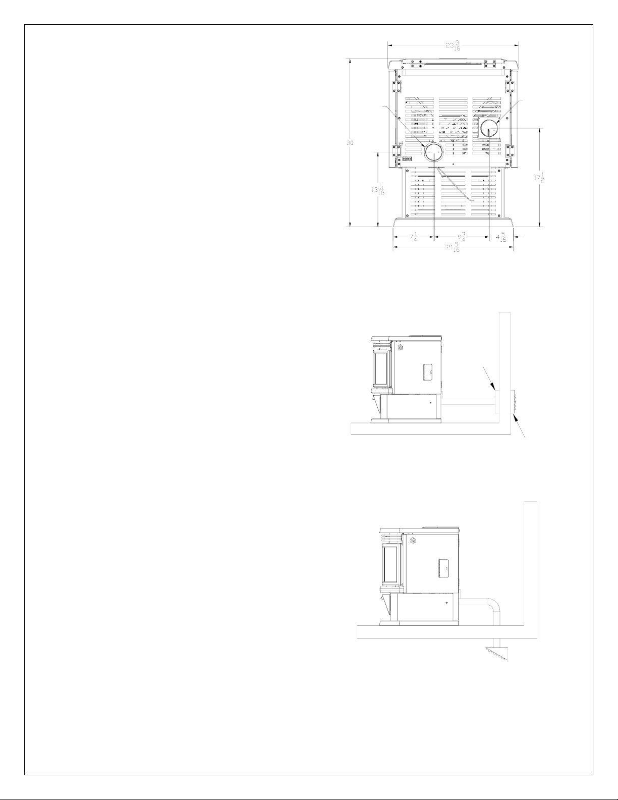
COMBUSTION AIR SUPPLY
For a mobile home installation the stove must be connected to an outside
source of combustion air. A 3” inside diameter metallic pipe, either flexible
or rigid, may be attached to the inlet at the stove’s rear (refer to figures 4, 5
& 6). A rodent guard (minimum 1/4” wire mesh) must be used at the
terminus (refer to figure 5). All connections must be secured and airtight by
either using the appropriately sized hose clamp and/or UL-181-AP foil tape.
For mobile home installations only: combustion air supply conduit may
not exceed 10 feet.
Sources of Outside Combustion Air
• A hole in the wall behind the stove.(Figure 5)
• A hole in floor near stove rear terminating only in a ventilated
crawl space.(Figure 6)
WHEN OUTSIDE AIR IS NOT USED
AIR
INTAKE
EXHAUST
If outside air is not used, it is important that combustion air be easily
available to the air inlet. A closable outside air register can be used in
tightly insulated homes.
VENTING
The HYBRID-35 is certified for use with Vent type UL-103 or ULC S629M
and Chimney type UL-641 or ULC S609, 3” or 4” diameter in size. This unit
can be vented in an existing chimney with the addition of a liner if the
chimney is more than 4” in diameter. Class “A” chimney is not required.
Refer to the instructions provided by the vent or chimney manufacturer,
especially when passing through a wall, ceiling or roof.
This is a pressurized exhaust system. All vent connector joints must be
sealed with 500°F (260°C) RTV silicone sealant to ensure consistent
performance and avoid smoke and ash spillage. All horizontal connector
joints must be sealed with UL-181-AP foil tape. We recommend that all
vertical vent connector joints be secured with a minimum of 3 screws.
DO NOT CONNECT THIS UNIT TO A CHIMNEY FLUE SERVING
ANOTHER APPLIANCE.
DO NOT INSTALL A FLUE DAMPER IN THE VENTING SYSTEM OF
THIS UNIT.
INSTALL VENT AT CLEARANCES SPECIFIED BY THE VENT
MANUFACTURER.
WARNING: DO NOT INSTALL IN BEDROOM
Figure 4
Rear view
TRIM
COLLAR
Figure 5
Fresh air supply
RODENT
GUARD
CAUTION: THE STRUCTURAL INTEGRITY OF THE MANUFACTURED
HOME FLOOR, WALL, AND CEILING/ROOF MUST BE MAINTAINED
VENTILATED
CRAWL SPACE
Figure 6
Ventilated crawl space
7
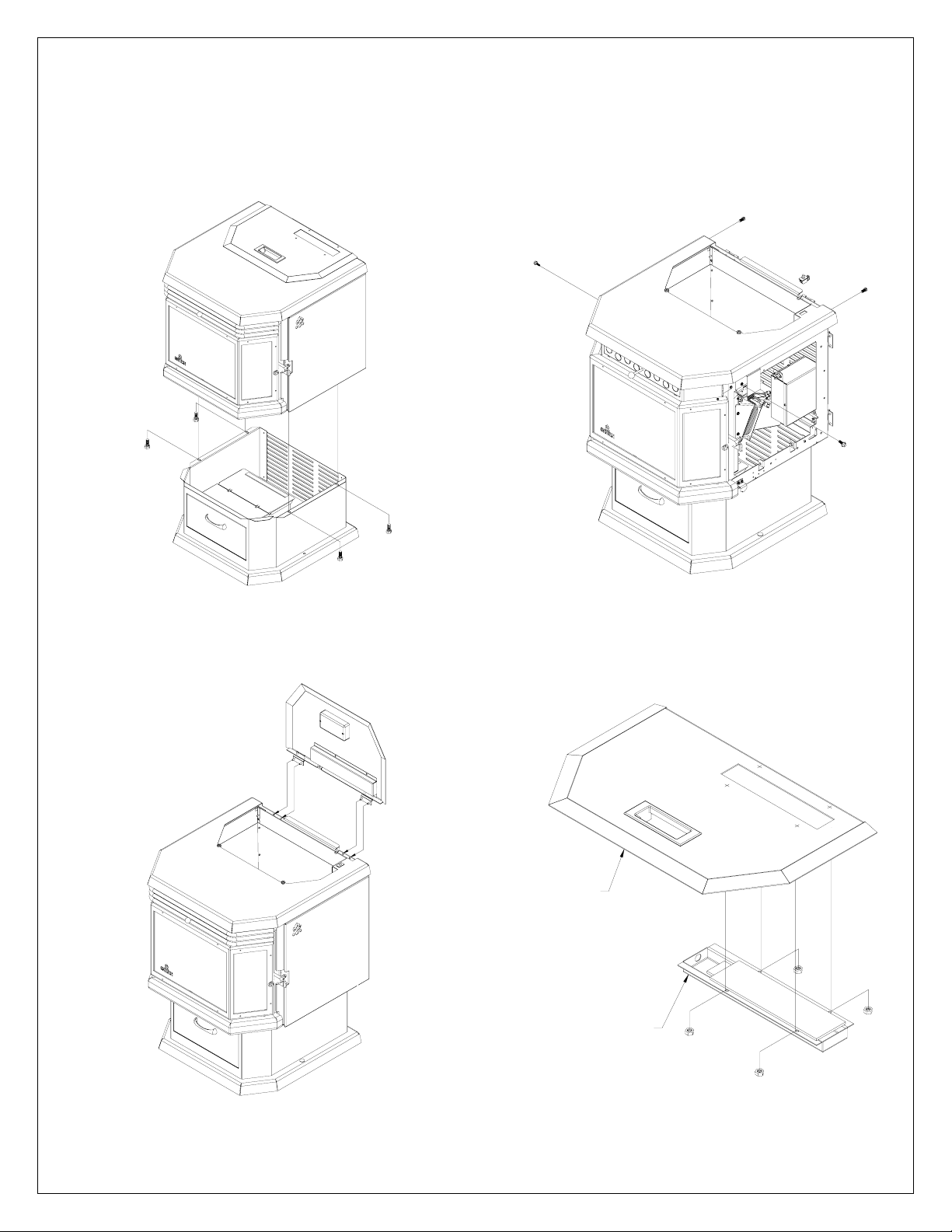
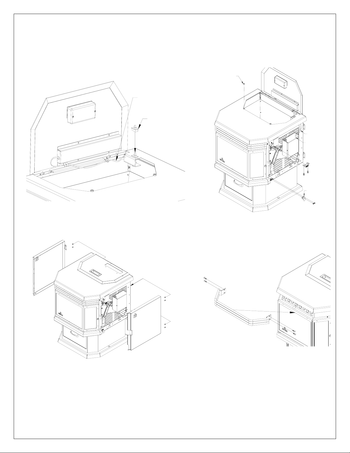
STOVE ASSEMBLY
1- Secure the stove to the pedestal with the 4 screws supplied.(Figure 7)
2- Secure the top to the stove with the brackets located on each side and 2 screws at the back of the
unit.(Figure 8)
Figure 7
3- Attach the hopper lid hinges to the stove with the 4 screws supplied (Figure 9)
4- Attach the control board to the hopper lid with the 4 nuts.(Figure 10)
HOPPER LID
Figure 8
CONTROL BOARD
Figure 10
Figure 9
8
5- Plug the lead with the white connector to the lid switch.
Run the other lead flat along the rear of the control panel, under the 2 tabs and attach to the tabs with Tywraps. Plug this lead to the control panel.(Figure 11)
6- Insert the rubber lid cover bumpers in the holes and attach side panel magnets and retainers as shown in
Figure 12.
HOPPER LID
RUBBER BUMPER
CONTROL
BOARD WIRE
LID
SWITCH
CONTROL
BOARD WIRE
LID SWITCH
WIRES
SIDE PANEL
RETAINER
Figure 11
Figure 12
7- Mount the side panels into place. Using 2 screws per hinge.(Figure 13)
8- Secure the louvers in front of the heat exchanger with the four screws supplied. (Figure 14)
Figure 14
Figure 13
9
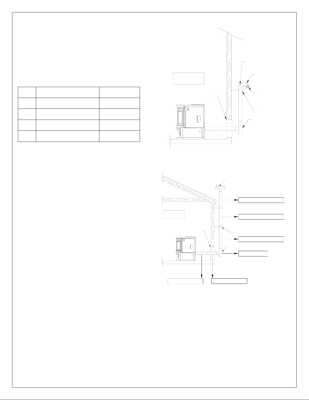
EQUIVALENT VENT LENGHT (EVL)
The longer the run of pipe in your installation, the more restriction there is
in the system. Therefore, larger diameter pipe should be used for longer
runs.
• Use 4” pipe if you have more than 15 feet of Equivalent Vent Length
(EVL).
• Horizontal runs shall not exceed 10 feet of EVL.
• To calculate EVL, use the following conversions table:
Qty Type of pipe EVL equivalent(ft)
1 90° elbow or “T” 5
1 45° elbow 3
1 ft Horizontal pipe run 1
1 ft Vertical pipe run 0.5
NOTE: At altitudes above 3,000 feet, we suggest the use of 4” diameter
vent at an EVL of 7 feet or more.
Here is an example on how to calculate the EVL of your installation. (See
Figure 16)
(3 x 4’ of vertical length = 12’ x 0.5 = 6 EVL) + (1 x elbow or "T" = 5 EVL) +
(2 x 1’ of horizontal length = 2 EVL)
Total EVL = (6 + 5 +2) = 13. So 3” diameter vent is allowed
INSTALLATION CONFIGURATIONS
HORIZONTALLY THROUGH WALL
(refer to Figure 7 & 8)
NOTE: Follow L-Vent chimney manufacturer’s instructions.
1. Position stove, adhering to clearances shown in Figures 1 & 2.
2. Determine position of hole in wall; directly behind stove exhaust vent
(refer to figure 4).
3. Always maintain 3” clearance from combustible materials.
4. Install L-Vent wall thimble per L-Vent manufacturer’s instructions.
5. Attach enough piping to go through and extend at least 6” beyond
exterior wall. An 8-foot vertical pipe run is suggested where possible
to reduce the possibility of smoke spillage caused by negative
pressure.
6. Attach cap and seal outside wall thimbles with non-hardening
waterproof mastic.
Termination should not be located so that hot exhaust gases can ignite
trees, shrubs, or grasses or be a hazard to children. Exhaust gases can
reach temperatures of 500ºF and cause serious burns if touched.
10
90 DEGREE ELBOW
FOLLOW CHIMNEY OR
VENT MANUFACTURER'S
INSTRUCTIONS
WALL
THIMBLE
45 DEGREE ELBOW
TERMINATION
COLLAR
WALL
STRAP
CLEAN OUT
TEE
Figure 15
Venting through wall
VERTICAL ROOF VENT
VERTICAL LENGTH 4' EVL = 4 X 0.5' = 2'
FOLLOW CHIMNEY OR
VENT MANUFACTURER'S
INSTRUCTIONS
1' HORIZONTAL RUN EVL = 1'
COUPE-FEU
MURAL
1' HORIZONTAL RUN EVL = 1'
VERTICAL LENGTH 4' EVL = 4 X 0.5' = 2'
WALL
STRAP
VERTICAL LENGTH4' EVL = 4 X 0.5' = 2'
CLEAN OUT
TEE
90° ELBOW "T" LEE = 5'
Figure 16
Venting trough wall
Locate terminations: a) not less than 3 feet above any forced air
inlet located within 10 feet; b) not less than 4 feet below or
horizontally from, or one foot above, any door, window or gravity
air inlet into any building; c) not less than two feet from an
adjacent building and not less than 7 feet above grade when
located adjacent to a public walkway. Mobile home installations
must use a spark arrester.
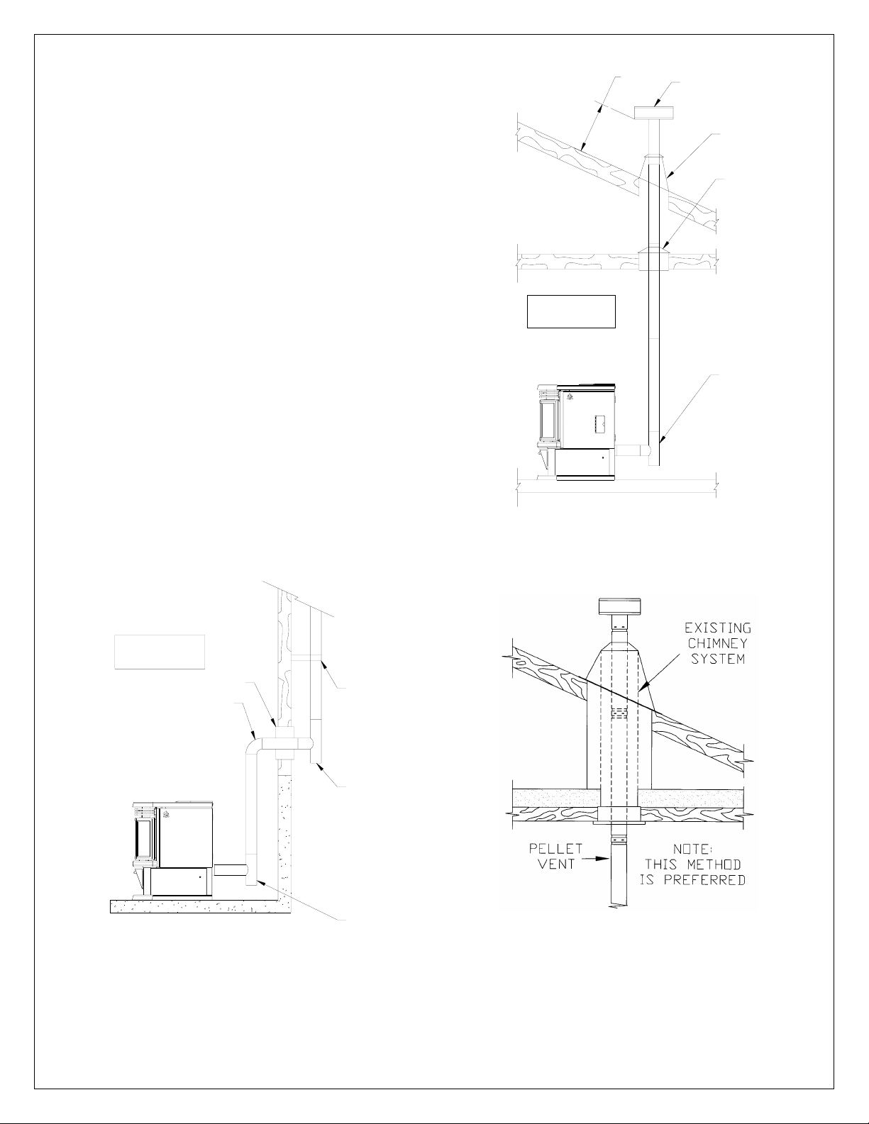
VERTICALLY WITH NEW CHIMNEY SYSTEM
N
(Refer to Figure 18 & 19 for basement installation)
NOTE: Follow L-Vent chimney manufacturer’s instructions.
OPTION: To achieve a centered vertical installation, a 45º elbow and a
clean-out tee can be used to offset the pipe from the exhaust outlet to the
rear center of the stove.
OPTION: Install L-Vent elbow in place of clean-out tee. Locate stove. Drop
plumb bob to center of tee outlet, mark point on ceiling. Install ceiling
support and L-Vent pipe per L-Vent manufacturer’s instructions.
1. Always maintain 3” clearance from combustible materials. When
passing through additional floors or ceilings, always install firestop
spacer.
2. After lining up for hole in roof, cut either a round or square hole in roof,
always 3” larger all the way around pipe. Install upper edge and sides
of flashing under roofing materials, nail to the roof along upper edge.
Do not nail lower edge. Seal nail heads with flexible waterproof
sealant.
3. Apply flexible, waterproof sealant where the storm collar meets the
vent. Slide storm collar down until it sits on the flashing. Seal and
install cap. Mobile home installations must use a spark arrester.
VERTICALLY INTO EXISTING CHIMNEY SYSTEM
As an alternative, 3” or 4” L-Vent can be run inside existing chimney to
termination(Figure 19). This is the preferred method.
Follow guidelines for equivalent vent length.
FOLLOW CHIMNEY OR
VENT MANUFACTURER'S
INSTRUCTIONS
12" MINIMUM
CLEARANCE
TO ROOF
VERTICAL ROOF VENT
STORM
COLLAR
ATTIC
INSULATIO
SHIELD
CLEAN OUT
TEE
Figure 17
Venting through roof
FOLLOW CHIMNEY OR
VENT MANUFACTURER'S
INSTRUCTIONS
WALL THIMBLE
FOR BASEMENT INSTALLATION
A 4" PIPE IS RECOMMANDED
Figure 18
WALL
STRAP
CLEAN OUT
TEE
CLEAN OUT
TEE
Figure 19
Venting through existing chimney
Basement installation
11
 Loading...