

Page 1
INSTRUCTIONS FOR O.S. PA-104 PUMP SYSTEM
The O.S. PA-104 Pump System consists of the unique O.S. Type PD-04 diaphragm fuel pump and matching large-throat
carburettor (O.S. Type 46), and has been developed specifically for O.S. MAX-40SF, 46SF, 40VF and 46VF engines.
The O.S. Pump System provides more power and ensures that fuel is delivered to the carburettor at the pressure reguired to
maintain the optimum mixture strength, irrespective of fuel tank location or aircraft attitude.
Note: This pump system cannot be fitted to the O.S. MAX-40FSR or 45FSR since the Type 46 carburettor cannot be installed in these engines.
PRINCIPLE OF THE DIAPHRAGM PUMP
Diaphragm
(oscillates as the pressure in the crankcase varies.)
Pump incorporates a regulator here
to maintain fuel outlet pressure at a
constant level.
Negative and positive pressures occur in these
chambers in accordance with upward and downward strokes of engine's piston.
Check Valve No.1. Negative pressure causes Check Valve 1to open and admit fuel from
tank to pump. Valve automatically closes under positive pressure to prevent reverse
flow.
Under negative pressure
Check Valve No 2 Positive pressure opens Check Valve 2 and delivers fuel to carburettor.
Valve automatically closes under negative pressure to prevent reverse flow
Figs 1 & 2 are merely diagrammatic to explain the principle of the
diaphragm pump. Actual construction is more complicated.
Under positive pressure
Fuel tank
Fig.1
Fig.
2
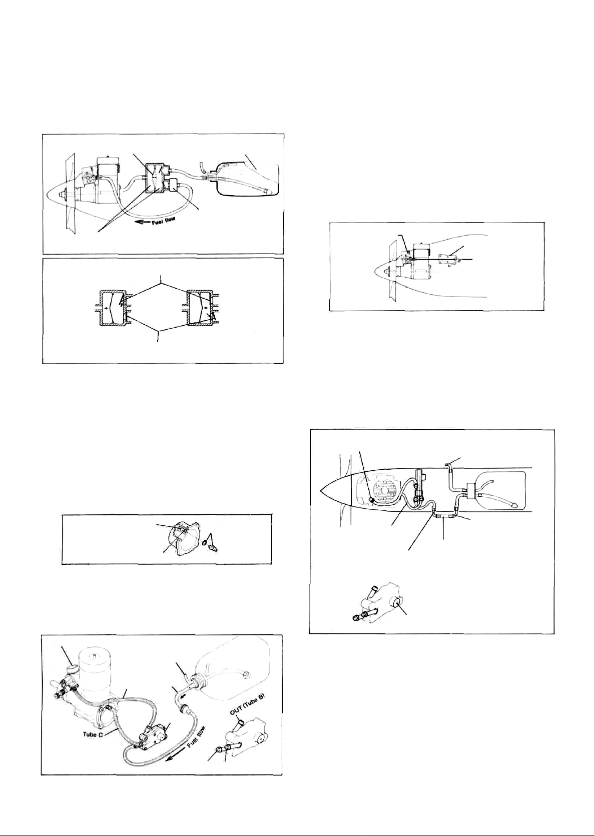
INSTALLATION OF PRESSURE NIPPLE AND CARBURETTOR
* Remove the crankcase cover-plate (backplate) from the engine.
Drill and tap cover-plate boss with M3.5x0.6 Metric thread and
fit nipple supplied.
Important! After tapping, be sure to wash out screw hole
thoroughly with kerosine.
Note:
For this modification, an M3.5 tap set, including a 2.9mm
drill for the pilot hole, is available as an optional extra
(Code No. 27901002). Alternatively, for owners who do
not care to do this work, a replacement cover-plate, complete
with nipple installed, is also obtainable (Code No.25407001).
* Refit cover-plate and install the O.S. Type 46 carburettor.
Make a pilot hole with
2.9mm drill.
Cut thread at least 5mm (3/16") deep
Nipple supplied
Fig.
3
PIPING
* For piping, use heavy duty silicone fuel tubing of approximately
2.5mm bore and 5mm outer diameter.
* A feature of the O.S. Pump System is that the fuel tank does
not have to be placed close behind the engine, but tube lengths
should be kept as short as possible. Take care not to cause any
kinks in the "plumbing".
Type 46 carburettor
Make sure that the length
of Tube C is less than
10cm
(4
in.).
Fig.
4
Tube A: To draw fuel from the fuel tank to the pump.
Tube B : To deliver fuel from the pump to the carburettor.
Tube C: To deliver the crankcase pressure pulse to the pump.
TubeB
Overflow
(Do not seal off)
TubeA
PD-04
IN (Tube A)
P (Tube C)
Fig.
INSTALLATION
Here are examples of typical installations. (Figs 6 & 7)
* The ideal location for the pump is one in which the center
of the pump is on the same level as the axis of the carburettor
barrel as shown in Fig. 6. In many cases, this cannot be achieved, precisely, within the existing structure of the airframe.
However, try to fit the pump as closely as possible to this
optimum location. If the pump is installed more than 5cm
(2 in) above or below the ideal position, there may be a slight
variation in fuel/air mixture strength between level and inverted
flight.
Type 46 carburettor
PD-04 pump
Carburettor center line
Fig.
6
Fix the pump on the firewall, front bulkhead, or side of the
engine compartment with 3mm self-tapping screws. It is advisable to insert a piece of sheet rubber between the pump and
mounting surface. DO NOT attach the pump directly to any
part of the engine.
If it is not possible to mount the pump as described, it may
be possible to wrap it in foam rubber and insert it into a convenient space in the engine compartment, but make sure that
it does not touch the engine itself.
Caution:
When installing the pump, take care that the vent hole in
the pump body is not obstructed.
Do not ill the tank from here,
or the pump may be damaged.
Overflow
L-shaped nipple or aluminum
tubing.
Silicone tubing
It may be convenient to lead the pipes
outside the fuselage and connect with
approx. 40~50mm(l-1/2~2") length
of silicone tubing.
Fig.
7
Fig.
8
Connect to the nipple
of the cover plate.
Disconnect here when
filling the tank.
Do not block or seal.
WARNINGS
* Do not dissassemble the pump
Never take the pump unit apart. Once the pump has been
dismantled, its original performance may not be restored when
it is reassembled.
* Do not insert anything into the nipples
Inserting a pin, etc., into the nipples and/or air vent hole is
likely to damage the pump and render it inoperative.
* Use fuel filters
Any foreign matter entering the Pump System may interfere
with its correct functioning and may even damage the pump
5
diaphragm. Be sure to filter, all fuel before filling the tank and,
most important, use a good quality fine filter in the delivery
tube between the tank and pump.
Page 2

FUEL TANK
If the fitting of the "klunk" type fuel pick-up weight in the fuel
tank is incorrect, the weight may stick to the tank wall, resulting
in an irregular fuel flow to the carburettor, or, alternatively, in
the fuel flow being cut off during the course of sharp acrobatic
manoeuvres. Therefore, it is advisable to make slots in the end of
the weight, with a file or hacksaw blade, as shown in Fig. 10.
Thoroughly wash out the weight to remove any minute particles
of metal before reinstalling it in the tank.
Use thick silicone tubing.
10-15mm
not
(3/8-5/8")
"froth"
in
Fig.
the
tank when
10
Fig.
9
STARTING THE ENGINE
1. Fill the fuel tank.
2. From its fully closed position, open the needle-valve approximately 1 to 1-1/4 turns (when the standard O.S. 873 silencer
is used), or 1-1/2 to 2 turns (when a tuned silencer is used).
3. Open the throttle fully.
4. Placing your finger over the carburettor to choke the intake,
turn the propeller by hand until fuel is pumped as far as the
carburettor.
5. When fuel is seen to reach the carburettor, remove your finger
from the intake immediately.
6. Close the throttle to the idling position and turn the propeller
through two extra revolutions to prime the engine. DO NOT
turn the prop more than this, or the engine will be over-primed.
7. Connect the battery to the glowplug and start the engine.
Note:
If the engine is over-primed (i.e. flooded), pinch the fuel
delivery tube (Tube B) with a suitable clip or clamp before
attempting to start the engine. If the engine remains overprimed and unwilling to start, close the needle-valve completely, remove the glowplug and flip the propeller briskly
to eject excess fuel from the cylinder via the glowplug hole.
8. Check that sufficient fuel can reach the engine to cause it to
run rich (for running-in purposes, etc.) when the needle-valve
is more than 3 turns open. If the engine cannot be made to run
rich, check as follows:
* Make sure that the fuel filter or carburettor is not partially
obstructed with foreign matter.
* Make sure that there are no holes in the piping or air bubbles
in the fuel flow.
*
Make sure
the engine is running. This can occur if the tank is not
properly insulated from vibration.
that
the
fuel does
* Make sure that the fuel pick-up weight is not being partially
obstructed by contact with the tank wall. (Refer to previous
instructions under "FUEL TANK".)
In the unlikely event that the engine cannot be persuaded
to run rich, after checking the above, it is possible that a
fault has developed in the pump. In this case, consult the
O.S. engine distributor in your country.
Coution:
In the throttle is 'blipped' rapidly and repeatedly between
the idling and medium speed positions during (for example)
taxying, an excess of fuel will be pumped into the engine.
The engine may then refuse to pick up speed, even when
the throttle is opened fully, and may stop. The throttle
lever should be opened gradually to match the engine's
natural acceleration under load. The recommended pre
take-off check is to fully open the throttle, once, with the
aircraft under restraint. The throttle is then returned to the
idling position, before being smoothly advanced for the
take-off run.
Time
Fi».11
ADJUSTMENTS
Adjustment of the PA-104 System is confined to the Type 46
carburettor. No adjustments to the pump are called for. Carburettor adjustment broadly follows the procedure for setting up
a conventional suction-feed system. See separate instruction leaflet
for O.S. Type 46 carburettor.
MAINTENANCE
If, after use, the fuel system is left unattended for a lengthy period,
there will be a tendency for the methanol content of the fuel to
evaporate sufficiently for the oil content to "gum" the internal
parts of the pump. Therefore, it is advisable, at the end of the
day's flying, to empty the fuel tank, invert the engine, and pump
out the remaining fuel in the system by rotating the propeller
until no more fuel is ejected from the carburettor.
If the pump is not in use for a while (more than one month),
remove the pump and wash out its interior by injecting methanol
or kerosene through the "IN" nipple. Fit the sealing caps (provided) to the nipples, after draining out the methanol or kerosene.
Note:
If you use kerosene, take care not to allow this to come into
contact with the fuel tubing, otherwise the tubing will swell
and deteriorate.
Time
© Copyright 1990 by O.S. Engines Mfg. Co., Ltd. All rights reserved. Printed in Japan
O.S.PUMP SYSTEM
Distributed in the United
States by permission of
Perry Aeromotive. Inc. under
U.S. Patent No. 3,96 7,606.
6-15 3-chome Imagawa Higashisumiyoshi-ku
Osaka 546, Japan. TEL. (06) 702-0225
FAX.
(06)
704-2722
 Loading...