

Page 1
FOUR CYCLE ENGINE
OWNER'S INSTRUCTION MANUAL
It is of vital importance, before attempting to
operate your engine, to read the general
•SAFETY INSTRUCTIONS AND WARNINGS'
section on pages 2-6 of this booklet and to strictly
adhere to the advice contained therein.
• Also, please study the entire contents of this
instruction manual, so as to familiarize yourself
with the controls and other features of the
engine.
• Keep these instructions in a safe place so that
you may readily refer to them whenever
necessary.
• It is suggested that any instructions supplied
with the aircraft, radio control equipment, etc.,
are accessible for checking at the same time.
FL-70
Page 2

CONTENTS
SAFETY INSTRUCTIONS AND WARNINGS
ABOUT
YOUR
O.S. ENGINE
ENGINE CONSTRUCTION ------------------------ 7
NOTES WHEN APPLYING AN ELECTTRIC STARTER ---INTRODUCTION
BEFORE STARTING ---------------------- 10-13
ENGINE
INSTALLATION ------------------------------------------------ 15-16
SILENCER & EXHAUST HEADER PIPE INSTALLATION ------- 17
FUEL
TANK & LINES --------------------------------
THROTTLE LINKAGE, NEEDLE-VALVE EXTENSION ------ 21
PROPELLER & SPINNER ATTACHMENT ---- 22-23
GLOWPLUG -------------------------------------------24
--------------------------
PARTS
NAME--------------------------------------14
----------------
2-6
9
18-20
TYPE 60W CARBURETOR, STARTING -------- 25-27
RUNNING -IN, CARBURETOR -------------------- 27-30
CARBURETOR AIR-BLEED ADJUSTMENT -------- 31
8
TROUBLE SHOOTING WHEN THE
ENGINE FAILS TO START-----------------------
VALVE ADJUSTING
HOW TO SET THE CAMSHAFT TIMING --------- 35
CARE AND MAINTENANCE ----------------------- 36-37
ENGINE EXPLODED VIEWS & PARTS LIST -------- 38-39
CARBURETOR EXPLODED VIEWS
& PARTS LIST ----------------------------------------
GENUINE PARTS & ACCESSORIES -------42-43
THREE VIEW DRAWING ---------------------------------
-------------------------------- 34
1
32-33
40-41
44
Page 3

SAFETY INSTRUCTIONS AND WARNINGS ABOUTYOUR O.S. ENGINE
Remember that your engine is not a "toy", but a highly efficient internalcombustion machine whose power is capable of harming you, or others, if it is
misused.
As owner, you, alone, are responsible for the safe operation of your engine, so act
with discretion and care at all times.
If at some future date, your O.S. engine is acquired by another person, we would
respectfully request that these instructions are also passed on to its new owner.
The advice which follows is grouped under two headings according to the
degree of damage or danger which might arise through misuse or neglect.
WARNINGS
These cover events which
might involve serious (in
extreme circumstances, even
fatal) injury.
NOTES
These cover the many other
possibilities, generally less obvious
sources of danger, but which, under
certain circumstances, may also
cause damage or injury.
2
Page 4
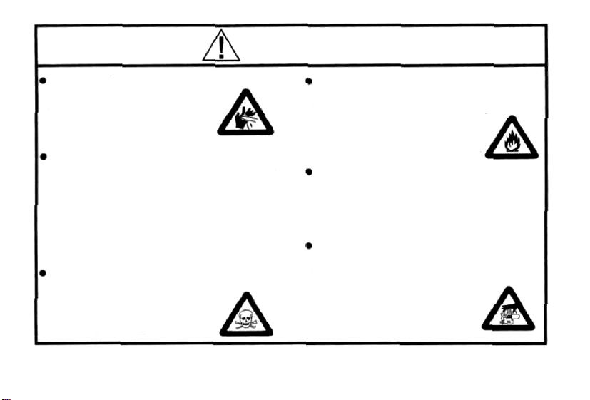
WARNINGS
Never touch, or allow any object to come
into contact with, the rotating
propeller and do not crouch
over the engine when it is
running.
A weakened or loose propeller may
disintegrate or be thrown off and, since
propeller tip speeds with powerful
engines may exceed 600 feet(180 metres)
per second, it will be understood that
such a failure could result in serious
injury, (see 'NOTES' section relating to
propeller safety).
Model engine fuel is poisonous. Do not
allow it to come into contact with the eyes
or mouth. Always store it in a
clearly marked container and
out of the reach of children.
Model engine fuel is also highly
flammable. Keep it away from open flame,
excessive heat, sources of sparks, or
anything else which might
ignite it. Do not smoke or allow
anyone else to smoke, near to it.
Never operate your engine in an enclosed space. Model engines, like automobile engines, exhaust deadly carbonmonoxide. Run your engine only in an
open area.
Model engines generate considerable
heat. Do not touch any part of your
engine until it has cooled. Contact with
the muffler (silencer),
cylinder head or exhaust
header pipe, in particular,
may result in a serious burn.
3
Page 5

NOTES
This engine was designed for model
aircraft. Do not attempt to use it for any
other purpose.
Mount the engine in your model securely,
following the manufacturers' recommenda-
tions, using appropriate screws and locknuts.
Be sure to use the silencer (muffler)
supplied with the engine. Frequent
exposure to an open exhaust may
eventually impair your hearing.
Such noise is also likely to cause
annoyance to others over a wide area.
If you remove the glowplug from the engine
and check its condition by connecting the
battery leads to it, do not hold the plug with
bare fingers.Use an appropriate tool or a
folded piece of cloth.
Install a top-quality propeller of the
diameter and pitch specified for the engine
and aircraft. Locate the propeller on the
shaft so that the curved face of the blades
faces forward-i.e. in the direction of flight.
Firmly tighten the propeller nut, using the
correct size wrench.
4
Page 6
NOTES
Always check the tightness of the propeller
nut and retighten it, if necessary, before
restarting the engine, particularly in the
case of four-stroke-cycle engines. If a
safety locknut assembly is provided with
your engine, always use it. This will prevent
the propeller from flying off in the event of a
"backfire", even if it loosens. Also, check
the tightness of all the screws and nuts
before restarting the engine.
If you install a spinner, make sure that it is
a precision made product and that the
slots for the propeller blades do not cut into
the blade roots and weaken them.
Preferably, use an electric starter. The
wearing of safety glasses is also strongly
recommended.
Discard any propeller which has become
split, cracked, nicked or otherwise rendered
unsafe. Never attempt to repair such a
propeller: destroy it. Do not modify a propeller
in any way, unless you are highly experienced
in tuning propellers for specialized
competition work such as pylon-racing.
Take care that the glow plug clip or battery
leads do not come into contact with the
propeller. Also check the linkage to the
throttle arm. A disconnected linkage could
also foul the propeller.
After starting the engine, carry out any
needle-valve readjustments from a safe
position behind the rotating propeller. Stop
the engine before attempting to make other
adjustments to the carburetor.
5
Page 7

NOTES
Adjust the throttle linkage so that the engine
stops when the throttle stick and trim lever
on the transmitter are fully retarded.
Alternatively, the engine may be stopped by
cutting off the fuel supply.
the engine physically.
Take care that loose clothing (ties, shirt
sleeves, scarves, etc.)do not come into
contact with the propeller. Do not carry loose
objects (such as pencils, screwdrivers, etc.)
in a shirt pocket from where they could fall
through the propeller arc.
Do not start your engine
containing loose gravel or sand.
The propeller may throw such material
your face and eyes and cause injury.
Never try to stop
in an area
For their safety, keep all onlookers
(especially small children) well back (at
least 20 feet or 6 meters) when preparing
your model for flight. If you have to carry
the model to the take-off point with the
engine running, be especially cautious.
Keep the propeller pointed away from you
and walk well clear of spectators.
Warning! Immediately after a glowplugignition engine has been run and is still
warm, conditions sometimes exist whereby
it is just possible for the engine to abruptly
restart if the propeller is casually flipped
over compression WITHOUT the glowplug
in
battery being reconnected. Remember this
if you wish to avoid the risk of a painfully
rapped knuckle!
6
Page 8
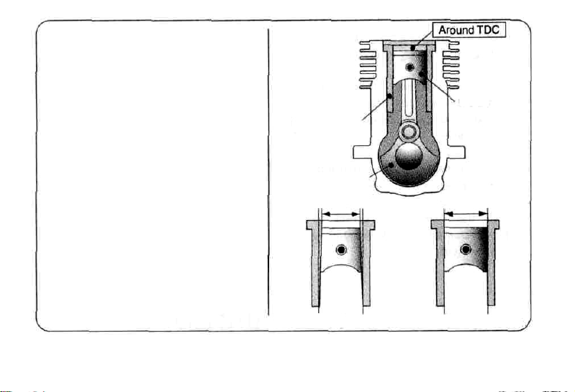
ENGINE CONSTRUCTION
With this engine, the piston will
feel tight at the top of its stroke
(TDC) when the engine is cold.
This is normal.
The cylinder bore Is a little
tapered.
The piston and cylinder are
designed to achieve a perfect
running clearance when they
reach their running temperatures.
Piston
Cylinder Liner
Crankshaft
A little tapered
When the engine is cold. When the engine is hot
Page 9

NOTES WHEN APPLYING
AN ELECTRIC STARTER
Do not over-prime. This could
cause hydraulic lock and damage
the engine on application of the
electric starter.
If over-primed, remove glowplug,
close needle-valve and apply
starter to pump out surplus fuel.
Cover the head with waste to
prevent pumped out fuel coming
into your eyes.
8
Page 10

INTRODUCTION
The
FL-70 is an air-cooled, overheadvalve four stroke engine for model aircraft
use. This engine is suitable for trainer,
sport and scale models.
This engine reduces maintenance by
incorporating the first O.S. ringless
piston/liner assembly. Also, a sealed front
bearing prevents oil leaks. The engine is
fitted with the new easy-to use O.S. 60W
airbleed carburetor. This engine
is
designed so that more R/0 pilots, from
hobby beginners to skilled Sunday fliers
may enjoy the performance advantages
of four stroke engines - greater fuel
economy, higher torque, lower noise and
realistic sund.
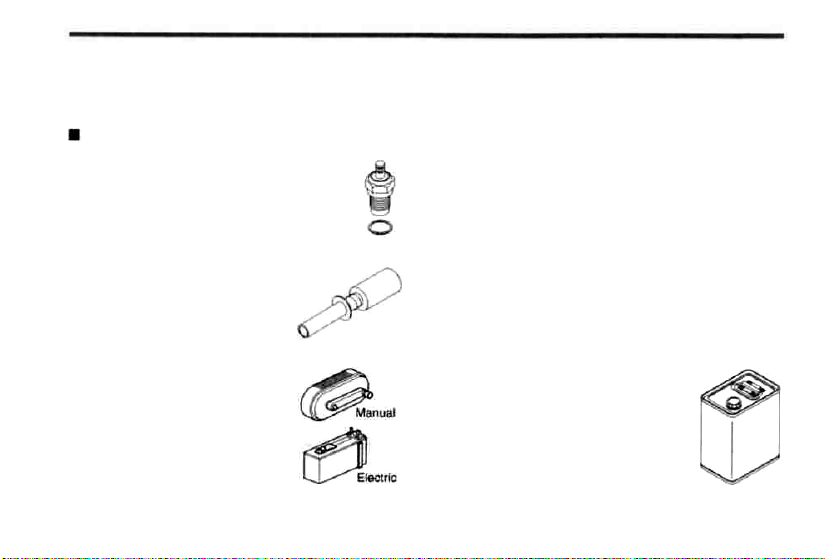
STANDARD ACCESSOIES
Glow Plug Type F
(fitted with the engine)
F-4030 Silencer Assembly
T Nipple
9
Page 11
BEFORE STARTING
Tools, accessories, etc.The following items are
necessary for operating the engine.
Items necessary for starting
GLOW PLUG
O.S. Type F glowplug is installed in the
engine.
GLOWPLUG IGNITER
Commercialy available handy
glowplug heater in which the
glowplug battery and battery
leads are integrated.
FUEL PUMP
Alternatively, one of the
purpose-made manual or
electric fuel pumps may be used
to transfer fuel directly from your
fuel container to the fuel tank.
FUEL
The FL-70 should be operated on a methanol
based fuel containing not less than 20%
(volumetric) castor oil, or a top quality synthetic
lubricant (or a mixture of both), plus a small
percentage (5-15%) of nitromethane for improved
flexibility and power. (The carburetor is adjusted at
the factory for a fuel containing 20% lubricant and
15% nitromethane.) Some commercial fuels also
contain coloring additives as an aid to fuel level
visibility. In some cases, these additives have
indicated slightly negative effects o performance.
We would suggest that you use such fuels only if
you are satisfied that they do not adversely affect
running qualities when compared with familiar
standard fuels. When changing to a fuel brand or
formula that is different from the one
to which you are accustomed, it is a
wise precaution to temporarily revert
to in-flight running-in procedures,
until you are sure that the engine is
running entirely satisfactorily.
10
Page 12
Reminder!
Model engine fuel is poisonous.
allow it to come into contact with the eyes or
mouth. Always store it in a clearly marked
container and out of the reach of children.
Model engine fuel is also highly flammable.
Keep it away from open flame, excessive
heat, sources of sparks, or anything else
which might ignite it. Do not smoke, or
anyone else to smoke, near to it.
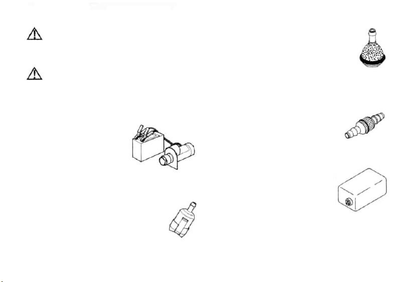
Electric Starter and
Starter Battery
Required when starting
the engine.
12- Volt lead-acid battery
Electric Starter
O.S. Super Filter (Fuel Can Filter)
Fit a filter to the outlet tube of your
refueling container to prevent entry of
foreign matter into fuel tank. O.S.
'Super Filters' (large and small) are
available as optional extras.
Do not
allow
O.S. Non-Bubble Weight
To prevent the pickup from adhering to
the tank wall under suction and
restricting fuel flow, slots may be filed
I the end of the weight. Alternatively,
O.S. Non-Bubble Weight is available
as an optional extra.
Fuel Filter
It is recommended to fit a good
in-line filter between the fuel tank
and carburetor to prevent entry of
foreign matter into the carburetor.
Fuel Tank
A fuel tank of approximately
300cc capacity is suggested.
This allows around 10 minutes
flying time, dependent upon the
type of fuel used, the size of propeller
the proportion of full-throttle to part-throttle
operation throughout the flight.
11
and on
Page 13
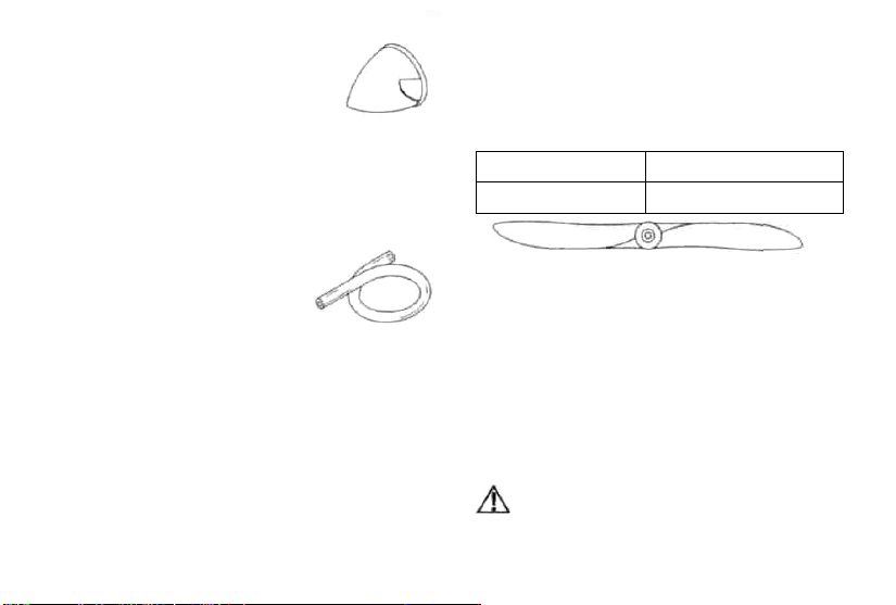
Spinner
Since the FL-70 is intended to be
started with an electric starter, the
addition of a spinner assembly for
centering the starter sleeve is desirable. Use a
heavy-duty, well balanced spinner either of
metal or plastic.
SILICONE FUEL LINE
Heatproof silicone tubing of
approx. 5mm o.d. and 2.5mm
i.d. is required for the
connection between the fuel
tank and engine.
Propellers
The choice of propeller depends on the design
and weight of the aircraft and o the type of
flying in which you will be engaged. Determine
the best size and type after practical
experimentation. As a starting point, refer to
the props listed in the accompanying table.
Slightly larger, or even slightly smaller, props
than those shown in the table may be used,
but remember that the propeller noise will
increase if blade tip is raised, due to higher
rpm or if a larger-diameter/lower-pitched prop
is used.
Sport & Aerobatic
Trainer & Scale
Warning:
Make sure that the propeller is well
balanced. An unbalanced propeller and/or
spinner can cause serious vibration which
may weaken parts of the airframe or affect
the safety of the radio-controlled system.
DO NOT forget the WARNINGS and NOTES
on propeller and spinner safety given
front pages.
Reminder!
Never touch, or allow any object to come Into
contact with, the rotating propeller and do not
crouch over the engine when it Is running.
12
12X7, 12.5X6, 13X6
12.5X6, 13X6-7
on
Page 14
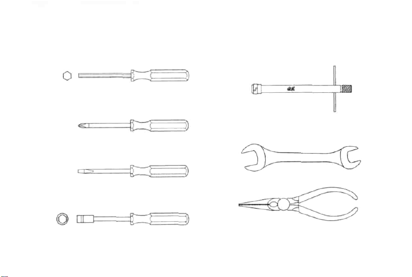
• TOOLS
HEX WRENCH
Necessary for engine installation.
1.5mm, 2mm, 2.5mm, 3mm opposite side
Plus Threaded Drivers
No.1,No.2,etc.
SCREWDRIVER
Necessary for carburetor adjustments.
No.1,No.2,etc
LONG SOCKET WRENCH WITH PLUG GRIP
Recommended for easy removal and
replacement of the angled and recessed
glowplug, the O.S.Long Socket Wrench
incorporates a special grip.
8mm
Spanners
8mm,
13mm, 14mm, etc.
Box Wrenches
5.5mm, 7mm, 8mm opposite side
Nipper
13
Page 15

Engine Parts Name
Glow Plug
Rocker Cover
Lock Nut Set
F-4030 Silencer Assembly
Nipple No.5
(Smaller hole)
Propeller Washer
Nipple No.1
(Larger hole)
Exhaust Header Pipe
Lock Nut
Silencer Body
Carburetor
Type 60W
Cover Plate
Crankcase
Beam Mount
Drive Hub
Rotor Guide Screw
Needle
Throttle Lever
Airbleed Screw
14
Page 16

INSTALLATION
Because the FL-70 is a powerful, large-displacement, single-cylinder four-stroke-cycle engine, it is
essential to use very substantial engine mounting. Conventional wooden mounting beams should be
of rigid hardwood and of at least 15mm or 5/8-in square section.
Make sure that the mounting beams are parallel and that their
top surfaces are in the same plane.
CORRECT
Front view Side view
Top surfaces are in the same plane.
Top surfaces are not
in the same plane.
Re-align the surfaces
as necessary
15
INCORRECT
Opposite beam
Top surfaces are not in the
same plane.
Engine does not rest firmly.
Page 17

How to fasten the mounting screws.
Hardwood mounting beams
Tighten second nut
3mm steel nuts
Spring washer or
lock washer
15mm
min
15mm min.
Radial motor mount
(cast aluminum)
firmlydown onto first nut.
Tighten this nut first.
Hardwood such
cherry or maple.
Steel washer
3mm steel screw
3mm steel Allen screw
Spring washer
• Make sure that these mounting beams are
accurately aligned and firmly integrated with
the airframe, reinforcing the adjacent
structure to absorb vibration. Use 3mm or
larger steel screws, preferably Allen type
hexagon socket head cap screws, with
washers and locknuts, for bolting the engine
to the bearers.
as
INSTALLING THE GLOWPLUG
Install washer on glowplug and
insert carefully into cylinder-head,
making sure that it is not crossthreaded before tightening firmly.
Glow plug
Washer
16
Page 18

SILENCER & EXHAUST HEADER PIPE INSTALLATION
Screw the header pipe into the cylinder head
until it "bottoms" , then unscrew sufficiently to
achieve the desired exhaust angle and tighten
the lock nut securely with a 14mm wrench.
Screw the silencer onto the outer end of the
header pipe and tighten the other locknut.
The application of a heatproof silicone sealant
to the threads of the exhaust system is
recommended to reduce the risk of joints
loosening and the leakage of exhaust gasses
and oil residue.
Reminder:
Model engines generate considerable heat
and contact with the header pipe or silencer
may result in a serious burn.
If you need to tighten the silencer joints,
which may loosen when they are hot, use a
thick folded cloth for protection.
Lock Nut
Exhaust Header Pipe
Apply silicone sealant.
17
Page 19

FUEL TANK & LINES
Make sure that the tank is well rinsed out
with methanol or glow fuel before installation
and that the pickup weight is well clear of
bottom of the tank when held vertically.
Connect between pressure nipple on the
silencer (larger hole one) and the tank to
apply muffler pressurized fuel feed system
which deliver the fuel stably reducing fuel
level negative effect.
Connect between breather nipple on the
cover plate and silencer breather nipple
(smaller hole one).
General Piping
Make connections as shown in the Fig.1.
An airbleed type carburetor is required to set
idling r.p.m. a little higher to prevent engine
cutting.
the
Piping suitable for acrobatic flights
With the general piping, the fuel in the tank
may flow into the silencer when the throttle is
set to slow during upside-down flight or
vertical dive, which may result in engine stop
due to mixture change at low speed. Piping
shown in the Fig 2 prevents fuel flowing into
the silencer, and engine stop at slow running
during maneuvers. Also, this piping allows to
set the idling r.p.m. a little lower and longer
flight by preventing excess fuel flowing out.
When the tank is filled (when the fuel level is
higher than the carburetor center line.),
prevent the fuel flowing into the carburetor
with a commercially commercially available
fuel stopper, etc. Release the stopper before
starting the engine.
18
Page 20

Fig. 1 General Piping
Note: When cutting silicone tubing,
use knife or razor blade.
No.1 Nipple (larger hole)
No.5 Nipple (smaller hole)
Fuel Fitter (commercially available)
T Nipple (supplied)
Plug (commercially available)
19
Silicone Tubing
If you should need to clean out silicone
tubes, use methanol or glow fuel, not
gasoline or kerosene.
Fuel Stopper (commercially available)
Refueling
tubing
Fuel Tank Center Line
Do not use wire cutter
or pliers.
Carburetor
Center Line
Approx. 10mm
Page 21

Fig. 2 Piping suitable for acrobatic flights
No.5 Nipple (smaller hole)
No.1 Nipple (larger hole)
Install the fuel tank so that carburetor
center line and fuel tank center line may
come to as much close as possible.
Fuel Filter
(commercially available)
Fuel Stopper
(commercially
available)
Plug (commercially available)
Refueling
tubing
20
T Nipple (supplied)
T Nipple
(commercially available)
Approx. 10mm
Page 22

THROTTLE LINKAGE
Before connecting the throttle to its servo,
make sure that the throttle arm and linkage
safely clear any adjacent part of the airframe
structure, etc., as the throttle is opened and
closed.
Connect the linkage so that the throttle is fully
closed when the transmitter throttle stick and
its trim lever are at their lowest settings and
fully open when the throttle stick is in its fullyopen position..
Carefully align
throttle arm and servo horn so that they move
symmetrically and smoothly through their
travel.
the appropriate
holes in the
full
NEEDLE-VALVE EXTENSION
The needle-valve supplied with this engine is
designed to incorporate an extension so that,
when the engine is enclosed within the
fuselage, the needle-valve may be adjusted
from the outside. Cut a commercially available
rod to the required length, bend one end to an
L shape, insert it into needle's center hole and
secure it by tightening the set-screw in the
needle-valve knob with 1.5mm Allen key.
Needle Valve Extension Cable Set (Code No.
72200080) is available from O.S.
optional part.
1.5mm Allen key.
Needle Valve Extension Cable Set
21
as an
Page 23

PROPELLER & SPINNER ATTACHMENT
There is a risk, particularly with powerful four-
stroke engines, of the propeller flying off if the
prop nut loosens due to detonation
("knocking") in the combustion chamber when
the engine is operated too
excessively heavy load.
Obviously, this can be very hazardous. To
eliminate such dangers, the O.S. Safety
Locknut Assembly was devised.
lean, or under an
3. Add the specially tapered and slotted
locknut and secure with a 10mm wrench
while holding the prop nut with the 13mm
wrench.
Propeller Washer
1. Ream the propeller shaft hole to 6.4-6.5mm
bore with an appropriate reamer, checking
that the hole is exactly centered.
2. Install the prop to the engine shaft, followed
by retaining washer and prop nut lightly.
Turn the prop counter-clockwise slowly to
locate the position where compression is
felt. At this position, fit the prop horizontally
and tighten firmly the prop nut with a 13mm
wrench.
Lock Nut
Propeller Nut
4. Fit a spinner assembly to start the engine
with an electric starter.
22
Page 24

Note:
Some spinners which are fixed at the top of
the cone cannot be used with the prop
locknut supplied with the engine. In this
case, optional locknut sets are available
from O.S. - Propeller Locknut Set for
Spinner (Code No.45810200) and Propeller
Locknut Set for Tru Turn Spinner (Code
No.145810300).
IMPORTANT
Regardless of the type of propeller fixing
used, make a habit of always checking the
tightness of the propeller before starting
the engine. Remember that, especially with
wooden propellers, there is a tendency for
the material to shrink, or for it to be
reduced by the serrated face of the drive
hub.
23
Page 25

GLOWPLUG
The FL-70 supplied with an O.S. Type F glowplug,
specially designed for O.S. four-stroke engines.
The role of the glowplug
With a glowplug engine, ignition is initiated by the
application of a 1.5-volt power source. When the battery
is disconnected, the heat retained within the combustion
chamber remains sufficient to keep the plug filament
glowing, thereby continuing to keep the engine running.
Ignition timing is 'automatic' : under reduced load,
allowing higher rpm, the plug becomes hotter and,
appropriately, fires the fuel/air charge earlier;
conversely, at reduced rpm, the plug become cooler and
ignition is retarded.
Glowplug life
Particularly in the case of very high performance
engines, glowplugs must be regarded as expendable
However, plug life can be extended and engine
performance maintained by careful use, i.e.:
Install a plug suitable for the engine.
Use fuel containing a moderate percentage
nitromethane unless more is essential for
events.
Do not run the engine too lean and do not leave
battery connected while adjusting the needle.
When to replace the glowplug
Apart from when actually burned out, a plug may
need to be replaced because it no longer delivers its
best performance, such as when:
Filament surface has roughened and turned white.
Filament coil has become distorted.
Foreign matter has adhered to filament or plug
body has corroded.
Engine tends to cut out when idling.
Starting qualities deteriorate.
24
of
racing
the
Page 26

TYPE 60W CARBURETTOR
Two adjustable controls are provided on this
carburettor.
They are as follows:
The Needle Valve
This is used to establish the
fuel/air mixture strength
required for full power when
the throttle is fully open.
The Airbleed Screw
This is used to establish the mixture strength
required tor steady idling and a smooth
transition to medium speeds. (The varying
mixture strength required between partthrottle and full-throttle running is
automatically adjusted by coupled movement
of the throttle.)
The sequence in which these controls are
adjusted is explained in the succeeding
sections, under Starting, Running-in and Idling
Adjustment.
Needle Valve
Airbleed Screw
STARTING
The FL-70 is not equipped with manual
choke controls, as it is intended for use
with an electric starter only.
A high-torque electric starter not only
makes starting the engine easier, it
dispenses with the need for a choke valve
by turning the engine over fast enough to
cause the fuel pump to prime the cylinder
automatically.
Starting procedure is as follows:
1.Fill the fuel tank with fuel. When filled,
prevent fuel flowing into the carburetor with
a commercially available fuel stopper, etc.
Release the stopper before starting the
engine.
2. Make sure that plug element glows
fit the plug to the cylinder head.
25
red, and
Page 27

Element glows when energized.
Pliers
Replace the plug when the
element does not glow or is
burnt out.
Glow Plug Igniter
WARNING
When checking the plug with energizing it,
hold the plug with tools, such as pliers, etc.
Do not bring your face close to the plug or
the boiled fuel remaining in the filament will
burn you.
3. Check that the current to the glowplug is
switched off.
4. To close the needle-valve, turn it
clockwise, while to open the
needle-valve, turn it counter-
clockwise. Turn the needle-valve
clockwise slowly until it stops.
This is the fully closed position.
5.0pen the needle-valve 2-2.5
turns from the fully closed
position and set the throttle in
the fully open position.
6. Apply the starter and press the starter
for 5-6 seconds to prime the engine.
7. Position the throttle stick at 2-3
advanced from the fully pulled down position.
Turn the prop "backwards" (clockwise) by
hand until it is arrested by compression. This
is to enable the kinetic energy of the prop to
subsequently assist the starter through the
compression stroke
to
start the engine.
26
Close
Open
Close
Fully opened
position
switch
scales
Page 28

8. Make sure that the rotating direction of the
electric starter is correct. Energize the
glowplug and apply the starter.
9. When the engine starts, slowly open the
throttle to the mid speed position. Then,
disconnect current to the glowplug. If at this
pint the engine stalls, it is probable that the
mixture is excessively rich. Close the
needle-valve a little and restart the engine.
10. Now close the needle-valve gradually so
that revolutions are increased.
How
to stop the engine
Pull down the throttle lever and trim lever on
the transmitter fully.
Note:
Make sure that the throttle
linkage is made so that the
throttle is fully closed when
the throttle lever as well as
trim lever on the transmitter
are
fully pulled down.
Close
RUNNING-IN ("Breaking-in")
For long life and peak performance, every
engine needs special treatment when new,
know as "running-in" or "breaking-in". This is a
procedure during which the engine is operated
under strictly controlled conditions at the
beginning of its life, in order to avoid the risk of
immediate damage to certain components
through becoming overheated or stressed and
to help working surfaces to become smoothed
and aligned for maximum mechanical
efficiency thereafter. With some engines, this
can require a tediously protracted period of
bench running, but, as O.S. engines are
manufactured to fine tolerances and from the
finest quality materials, a relatively brief
running-in period is sufficient and can be
completed with the engine installed in the
aircraft. Prolonged running with too rich
mixture and/or low speed will not complete the
proper running-in.
27
Page 29

On
the contrary, prolonged low speed running
may cause the oil in the fuel gelled, which may
result in seizure of the piston and cylinder liner.
The recommended procedure is as follows:
1. Use the same fuel and prop as you intend
for flying your model.
2. Open the needle-valve
2.5 turns from the
fully closed position and start the engine.
3. Open the throttle slowly to the mid speed
position, and disconnect the current to the
glowplug.
4. Now open the throttle slowly to the
fully
opened position and run the engine for no
more than 5 seconds with the needle-valve
tuned to produced near maximum r.p.m.,
then, immediately, slow the engine down
again by opening the needle-valve
approximately one turn. The rich mixture, so
induced, will cool the engine, at the same
time providing increased lubrication.
5. Repeat this process, alternately running the
engine fast and slow by means of the
needle-valve, while keeping the throttle fully
open, then begin to extend the short
periods of high-speed operation until two
tanks of fuel have been consumed.
WARNING:
When ground running the engine, avoid
dusty or sandy locations. If dust or grit is
drawn into the engine, this can be a
ruinous effect, drastically shortening
engine life ion a matter of minutes.
6. Following the initial running-in session,
check for any looseness in the installation
due to vibration, then allow the engine a
period of moderately rich operation in flight.
7. For the first flight, have the needle-valve set
on the rich side and adjust the throttle trim
on the transmitter so that the engine does
not stop when the throttle is closed to the
idle setting.
28
Page 30

8. With each successive flight, close the
needle-valve very slightly until, at the end of
about 10 flights, the needle is set for full
power. Do not "over-lean" the mixture in an
attempt to extract more power.
If overheating should be suspected at any
time during flight (i.e.if the engine begins to
"labor") reduce power by partially closing
the throttle and land the aircraft to enable
the needle-valve to be readjusted to a
richer setting.
CARBURETOR
These engines are equipped with a throttle
type car-buretor which provides a wide range
of engine speed control. With the throttle lever
linked to a suitable servo in the model,
movement of the throttle control on the
transmitter will enable engine to be varied,
proportionally, from idling speed to full power.
The carburetor of your engine has been factory
set for the approximate best results and no
adjustment (except to the needle-valve) should
be required provided that the fuel tank is
correctly located, as previously described.
After the engine has been run-in, check the
operation of the throttle according to the
following chart. Re-adjust the controls only
when necessary.
29
Page 31

Re-set the idling
alittle higherr.p.m.
position
Make
sure that the throttle is
fullyopen
Adjust the neede-valve.
Close the throttle gradually
Find the idling position.
Fix the idling position.
at
Open the throttle fully.
Start the engine
20-30' open from maximum
rp.m setting.
The position where the lowest
possible r p m .with steady
running, is obtained.
Set the throttle opening by
means of the throttle trim on
the transmitter so that the lowest
practical speed, without risk of
the engne stoppingis obtained.
Engine stops.
Engine stops.
Engine stops.
Refer to the CARBURETOR
AIR-BLEED ADJUSTMENT
section on page 31
Does the engine
regain full power?
Continue running at high speed
lor 10 seconds
Close the throttle.
Run at idling speed lor 5 seconds.
Does the engine slop?
Apply full throttle
Does the engine
regain full power
immediately'?
OK
Yes.
No.
Yes.
Page 32

CARBURETOR AIR-BLEED ADJUSTMENT
Pre-Flight Check
Start engine and adjust needlevalve as previouslv described.
Close the throttle gradually.
Find the idling position.
approx
15 degrees
Hold the model.
Hold model level, then slowly raise the nose.
Stop the
If rpm increases.
engine.
Note: Stop engine
pinching fuel line
Do not touch
needle-vatve.
These adjuslments
made without stopping
the engine.
However, it is advisable for
beginners to slop the engine
for safety reasons.
by
can be
If
engine runs
Immediatety point
nose down. so that
engine runs steadily
again
unevenly
approx
15 degrees
Stop the engine.
or
stops.
Open air bleed
screw.
Half turn at a
time.
Close air-bleed
screw.
time.
Attention: Do not leave the glowplug connected to the
battery while adjusting the carburetor throttle.
Half turn at a
Page 33

TROUBLE SHOOTING WHEN THE ENGINE FAILS TO START
Four key points
For
quick, reliable starting, the following four conditions are required.
(1.) Good compression. (2.) Adequate "glow" at glowplug. (3.) Correct mixture.
(4) Sufficient electric starter rotating speed.
If the engine fails to start, or does not keep running after being started, check symptoms against the
following chart and take necessary corrective action.
Note: The most common causes of trouble are marked with three asterisks, the less common problems
with one or two asterisks.
Symptom
Engine falls
to fire.
Factor
Cause
Sluggish
rotation
......
Glowplug
battery
discharged, unused, dry battery may sometimes be of insufficient capacity if it is "old
Glowplug element Is • • • • • Replace glowplug. Check that applied voltage Is not too high.
burned out
Something wrong with . . • • Check glowplug heating using other leads
battery leads.
Engine "flooded" due to • • • • Close needle-valve fully and remove glowplug, then Hip propeller to pump
excessive priming, out excess fuel. (Invert engine, if possible, white pumping out excess). Re-
Insufficient priming. ..... Repeat priming procedure referring to Priming.
......
Recharge the
Recharge
lead-acid
stock".)
start engine. (Priming is not necessary at this lime.)
Corrective action
electric
starter battery.
cell
or
replace
dry
battery.
(Note:
An
unused,
or
almost
32
Page 34

Symptom
Engine fires
Intermittently but
does not run.
Engine fires once
or twice, then
tails to lire.
Engine starts but
rpm decreases
and engine eventually
stops.
Engine starts.
rpm increases
and engine cuts
out.
Engine stops when
the current to the
glowplug is disconnected after starting
Factor
Cause
Incorrect heating of ..... Voltage too high or too low. Re-check and readjust referring to "BEFORE
glowplug. STARTING".
Over priming.
Sluggish rotation. •••••• Then re-start. (Priming is not necessary.)
Glowplug battery •••••• Recharge lead-add cell or replace dry battery.
discharged. (Note: An unused, or almost unused, dry battery may sometimes be of
I
nsufficient priming. • • • • • Repeat priming procedure referring to Priming.
Mixture too rich. ••••••• Close needle valve hall turn (180") and wait for several minutes then re-
Fuel not reaching the • • • • • Make sure that tank is filled with fuel. Check that there Is not something
engine, wrong with the fuel line (kinked or split). Check that carburettor is not
Mixture
Mismatch of glow plug and- • • Change fuel or glowplug.
..••••••
too
rich.
.......
Continue applying an electric
than 4 tries, disconnect the current to the glowplug and leave for a few
minutes., then re-energize plug and apply starter. If the engine still does not
start, remove glowplug and pump out excess fuel by applying the starter.
Recharge the electric starter battery.
insufficient capacity it it is "old stock".)
start (Priming is not necessary.)
clogged with dirt.
Close the needle-valve a
Corrective action
starter.
II
the
engine
little
before
disconnecting
does
current
not
start
to the
after
glowplug.
more
33
Page 35

VALVE ADJUSTING
Valve clearances are correctly set before any
O.S. engine leaves the factory and, in normal
use, will seldom require adjustment. However,
if, after a very considerable amount of running
time has been consumed, a loss of power is
detected, or if he engine has been
disassembled for repair, these clearances
should be checked and reset as necessary.
For checking and adjusting the valve
clearances, VALVE ADJUSTING TOOL KIT is
available as an optional accessory.
The kit comes in a plastic case and includes:
(Code No.72200060)
• Feeler gauge 0.04mm
• Feeler gauge 0.1 mm
•
Hex. key 1.5mm
• Wrench 5mm
34
Page 36

HOW TO SET THE CAMSHAFT TIMING
When replacing the camshaft, set the timing as
follows.
1. Secure propeller.
NOTE:
If propeller is not secured, crankshaft may
move backward and correct timing cannot
be set.
2. Turn the crankshaft so that T mark on the
drive hub may match crankcase center line.
(This is engine T.D.C. position)
3. Push the camshaft into camshaft housing
until it stops. Locate ' •' mark on the side of
camshaft gear in line with the push rod.
4. Rotate crankshaft right and left a little
make sure that the ' •' mark on the gear is in
line with the push rod when the ' T ' mark
the drive hub matches the crankcase center
line.
5. Secure cam cover with screws.
and
on
The relation of position between ' • ' mark of
the gear and teeth may differ from the sketch,
by each model.
crankcase
center line
T mark on
the drive hub
35
mark
Fig.2
in line with
the push rod
camshaft gear
camshaft
mark of the
Page 37

CARE AND MAINTENANCE
Please pay attention to the matters
described below to ensure that your engine
serves you well in regard to performance,
reliability and long life.
•As previously mentioned, it is vitally important
to avoid operating the engine in conditions
where dust, disturbed by the propeller, may
be deposited on the engine and enter its
working parts.
• Fit an in-line fuel filter between the tank and
carburetor to prevent dist and dust in the
tank entering the carburetor.
• Clean these filters periodically.
• If these precautions are neglected, restriction
of fuel flow may cause the engine to cut out,
or the fuel/air mixture to become too lean
causing the engine to overheat.
• Remember to keep your fuel container
closed to prevent foreign matter from
contaminating the fuel.
• Fit a fuel can filter to prevent dirt and dust in
the fuel container entering the fuel tank.
O.S. Super Filters (L) and (S) are available
as optional extra.
• The use of modern high-performance alcohol
based model engine fuels, while promoting
cooler running, improved anti-detonation
combustion and increased power, has the
disadvantage of causing bottom end
corrosion in a four-stroke engine. This is due
to the acidic by products of combustion that
accumulates in the engine's crankcase and
are not flushed out by fresh air/fuel mixture
as in the case of a two-stroke engine.
36
Page 38

The use of nitromethane in the fuel can also
contribute to the problem. As a primary
defense, users are advised to avoid running
the engine on too lean a mixture - i.e. do not
close the needle-valve and the airbleed
screw too much.
• Do not leave unused fuel in the engine at the
conclusion of a day's flying. Accepted
practice is to cut off the fuel supply while the
engine is still running at full throttle, then
expel as much fuel residue as possible by
turning the engine over 5-10 seconds with
the electric starter. Finally, inject some after-
run oil through the glowplug hole and turn the
engine over several times by hand.
• When the engine is not to be used for some
months (for example, as between flying
seasons), a worthwhile precaution is to
remove it from the airframe and, after
washing off the exterior with alcohol (not
gasoline nor kerosene), remove carefully the
carburetor with intake pipe, glow plug and all
silicone tubing and put them safely aside.
Then, immerse the engine in a container of
alcohol. Rotate the crankshaft while the
engine is immersed. If foreign matter is
visible in the alcohol, rinse the engine again
in clean alcohol. Finally, shake off and dry
the alcohol ,and inject some after-run oil from
glowplug hold and rotate the crankshaft
several times by hand. Re-fit the carburetor
with intake pipe and glowplug with the engine
and keep it dry place after putting in a vinyl
bag.
37
Page 39

ENGINE EXPLODED VIEW
*Type of screw
C Cap Screw
F...Flat Head Screw N. .Round Head Screw S...Set Screw
B..Binding
Head Screw M.. Oval
Fillister-Head
Screw
Page 40

No.
2
2-1
2-2
3
3-1
3-2
4
4-1
4-2
4-3
4-4
5
5-1
5-2
5-3
5-4
6
7
8
9
10
11
12
13
14
15
16
17
18
19
20
21
22
23
23-1
23-2
24
25
26
27
28
29
29-1
29-2
29-3
1
Code No
44404200
45961400
45961410
45761600
44753000
44753100
45761200
44460000
44460100
45960210
45060309
46160400
44461000
44461100
45960210
45060309
46160400
44404100
44404000
44481000
44714100
44403000
45906000
44405000
44407009
44407000
44402000
44408100
44430000
44401000
44462000
44401100
44701109
44766000
44766100
44766110
24881824
45664000
44731000
44408000
23209003
44410000
44425000
44425100
45926100
45626030
71615009
29084610
Rocker Cover
Rocker Support Assembly
Rocker Support
Rocker Arm Retainer (2pcs.)
Rocker Arm Assembly (1pair)
Rocker Arm (1pc.)
Tappet Adjusting Screw
Intake Valve Assembly (1 pair)
Intake Valve (1pc.)
Valve Spring (1pc.)
Valve Spring Seal (1pc.)
Valve Spring Retainer (2ps.)
Exhaust Valve Assembly (1pair)
Exhaust Valve(1pc.)
Valve Spring (1pc.)
Valve Spring Seat (1pc.)
Valve Spring Retainer (2ps.)
Cylinder Head(W/Gasket)
Cylinder Head (W/Gasket and Valve Assembly)
Carburetor Complete (60W)
Head Gasket
Cylinder & Piston Assembly
Piston Pin
Connecting Rod
Cover Plate Retaining Screw
Cover Plate
Crankshaft
Drive Pin
Crankshaft Ball Bearing (Rear)
Crankcase
Camshaft
Cam Cover
Cam Cover Retaining Screw
Push Rod (2pcs.)
Push Rod Cover Assembly (2pcs.)
Push Rod Cover (1 pcs.)
Push Rod Cover "0" Ring (2pcs.)
Cam Follower (2pcs,)
Crankshaft Ball Bearing (Front)
Drive Hub
Propeller Washer
Lock Nut Set
F-4030 Silencer Assembly
Silencer Body
Exhaust Header Pipe Assembly
Manifold Nut (M11)( 1pc.)
Glow Plug Type F
T Nipple (1pc.)
Description
Specifications are subject to alteration for improvement without notice.
Page 41

CARBURETOR EXPLODED VIEW
*
Type of screw
C Cap Screw B Binding Head Screw M Oval Fillister-Head Screw
F...Flat Head Screw N. Round Head Screw S .Set Screw
40
Page 42

CARBURETTOR PARTS LIST
No.
Code No.
1
22081408
1-1
22081313
2
44481200
44481100
3
4
45915000
5
22681980
24981837
5-1
5-2
26381501
6
44481960
26711305
6-1
6-2
45281920
6-3
22681953
7
44481310
Specifications are subject to alteration for improvement without notice.
Throttle Lever Assembly
Throttle Lever Retaining Screw
Carburetor Rotor
Carburetor Body
Carburetor Rubber Gasket
Needle-valve Assembly
"0" Ring (2pcs.)
Set Screw
Nozzle Assembly
Ratchet Spring
Nozzle Retaining Screw (2pcs.)
Fuel Inlet (No.1)
Air-bleed Screw
Description
41
Page 43

O.S. GENUINE PARTS & ACCESSORIES
O.S.GLOW PLUG
TYPEF
(71615009)
0
Needle Valve Extension
Cable Set _
(72200080)
BOOSTER CABLE SET
(72200110)
BOOSTER
TERMINAL KIT
(72200130)
PROPELLER
LOCKNUT SET
(45810100)
(45810200 For Spinner)
PROPELLER LOCKNUT SET
FOR TRU-TURN SPINNER
1/4"-M5 (45810300)
FLEXIBLE EXHAUST PIPES
Length
Code.No.
72108100
72108110
72108120
72108130
Type
1111A
HUB
1111C
1111D
(mm)
120
240
170
330
42
EXHAUST HEADER PIPES
(72109500) (72109600)
Inside
Outside
Page 44

NON-BUBBLE WEIGHT
(71531000)
SUPER FILTER (L)
(72403050)
LONG SOCKET WRENCH
WITH PLUG GRIP
(71521000)
VALVE ADJUSTING
TOOL LIT
(72200060)
LOCK WASHER
M3
(10sets)
(55500002)
BLIND NUT (10pcs./sets)
M3
(79870030)
The specifications are subject to alteration (or improvement without notice.
43
CAP SCREW SETS (10pcs./sets)
M2.6x8 (79871025)
M2.6x10(79871030)
M3.5x12(79871080)
M3.5x20(79871100)
Page 45

THREE VIEW DRAWING
Specification
Displacement
Bore
Stroke
Practical R.P.M.
Power output
Weight
(Silencer
including
exhaust header pipe)
11.45cc(0.698cu.in.)
27.7mm (1.090 in.)
19.0mm (0.748 in.)
2.300-12.000 r.p.m.
1.1ps/ 11.000 r.p.m.
467g (16.480Z.)
51.5g(1.8oz.)
Dimension(mm)
44
Page 46

6-15 3-Chome Imagawa Higashisumiyoshi-ku
Osaka
546-0003. Japan TEL. (06) 6702-0225
URL:
(C) Copyright 2004 by O.S.Engines Mfg. Co.. Ltd. All rights reserved. Printed in Japan. 60091500 050400
FAX. (06) 6704-2722
http://www.os-engines.co.jp
 Loading...