

Page 1
APRIL 2001
PUBL. NO
486 7328-ENG
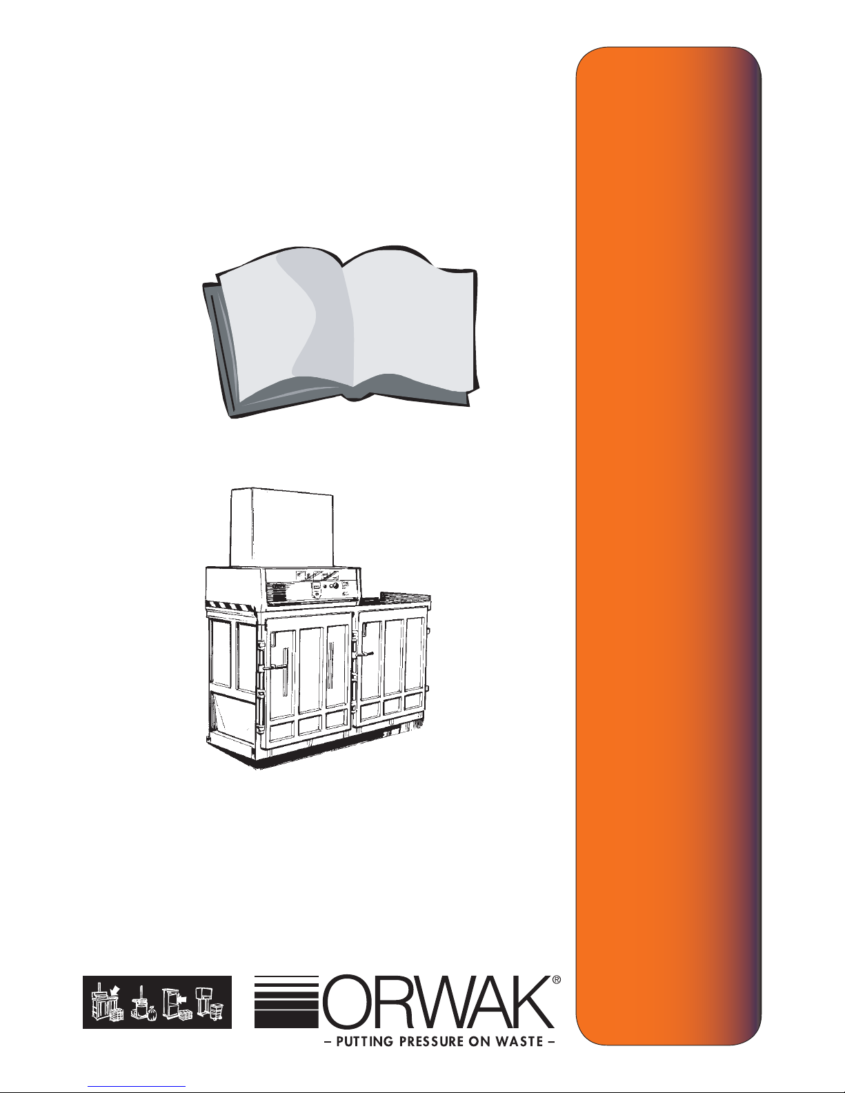
OPERATING INSTRUCTION
ORWAK 8020
MAJ 2002
PUBL. NO
91 644-00
Page 2
2
3
8020
TABLE OF CONTENTS
GB
OPERATING INSTRUCTION
SAFETY 3
Operating instruction 4-6
Data 7
Transport 8
Inspection/ Maintenance 9
Instruction for installation 10
CE 11
Page 3
3
8020
SAFETY INSTRUCTIONS
GB
Read, learn and understand the text as it concerns safety.
Follow the instructions carefully to avoid accidents.
Read this instruction before operating the ORWAK 8020. It should only be used by
trained operators. Learn the operating functions before using the machine and
follow the instructions so that maximum safety is achieved.
This symbol means WARNING or DANGER - PERSONAL SAFETY INSTRUCTION
The ORWAK 8020 is designed for ONE MAN OPERATION.
ONLY THE OPERATOR IS ALLOWED IN THE WORKING AREA.
Only trained operators are allowed to use the machine. Materials easily to set on re
or of an explosive nature, such as cans with residual low ash point liquids, or any
thing which could cause damage or explosion must not be compacted in the ORWAK
8020 baler.
The machine must not be used if the safety functions have been interfered with such
as the opening of the head covers or limit switches.
If the machine needs to be moved, the press plate must be lowered fully
before moving.
When cleaning or when service etc. is done, on the outer as well as the
inner parts of the machine, then the chamber must be emptied and the
power supply must be shut off.
LOCATION.
The ORWAK 8020 is insulated to IP 55 so can be used in damp locations but
not in areas which are hazardous locations. Always check the local regulations.
Page 4
4
5
8020
SAFETY FEATURES
GB
The machine is equipped with the following safety features :
The Main switch can be secured with a pad lock to prevent unauthorised use or
when servicing the machine.
The Emergency Stop Switch breaks the electrical circuit immediately it is
used. When the switch is reset the machine will not restart. The start button
has to be pressed again. The press plate always returns upwards to a safe
position.
Target, mechanical and electrical limit switches prevent the machine being
used with the doors open or when the press head is moved between
chambers.
Front and rear covers protects the operator from moving parts of the machine.
The electrical circuits of the machine are protected by a circuit breaker
which also serves to protect the motor.
Page 5
5
8020
PRODUCT SPECIFICATION
GB
The ORWAK 8020 is a unique baling press with advanced construction and
design. IF well maintained the ORWAK 8020 will give many years of reliable
service.
The ORWAK 8020 is a quality product. As a quality aware Company AB
ORWAK wishes to see that the ORWAK 8020 is used only for the correct
purposes and that the safety instructions are followed. The Instruction Manual
should be read thoroughly so that the ORWAK 8020 can be installed, operated
and maintained properly.
Our warranty requires that the usage and safety instructions are followed and
that only original spare parts and recommended hydraulic oil and lubricants are
used.
MACHINE identity plate.
The machine identity plate is located at the front of the press head. It gives the
following data: machine type, serial number, month and year of manufacture
and electrical data.
The user of the machine is responsible for the safety checks,
inspections and carrying out the daily maintenance routine.
The user is responsible for ensuring that any faults are corrected and
that the ORWAK 8020 is maintained in such condition so as to avoid
accidents to any operator.
The owner is responsible for ensuring that all National and Local Laws
are complied with when using the ORWAK 8020.
Page 6
6
7
8020
RAGE OF APPLICATON
GB
The ORWAK 8020 is an hydraulically driven baler used mainly toreduce the volume
of bulky materials such as paper, plastic and light wooden boxes.
Materials easily to set on re or of an explosive nature, such as cans with
residual low ash point liquids, or anything which could cause damage or
explosion must not be compacted in the ORWAK 8020 baler.
The machine must only be placed in spaces with a roof, protection against wind
and normal lighting.
The machine has up to six chambers which allows the easy segregation and
baling of differing materials. The press head moves freely over these chambers.
The hydraulic pump is powered by a three phase electrical motor.
The ORWAK 8020 is operated from a control panel on the front of the machine.
The electrical connection is made by a 5 wire insulated cable which is connected to
the power supply via an isolating wall socket, see instruction for installation.
The electrical control box and the hydraulic power pack with the operating valve are
located within the press head. There is easy access to all these components at the
front of the machine.
Page 7
7
8020
HYDRAULIC SYTEM
GB
Hydraulic two staged gear wheel pump, driven by an electrical motor.
The hydraulic functions consists of an electrical directional valve, pressure
switches and two hydraulic cylinders to move the press plate up and
down.
Relief valve to prevent over pressure in the hydraulic system.
Filter on suction side of hydraulic pump.
Check valve on outgoing ow line from hydraulic pump.
ELECTRICAL SYSTEM
Electrical voltage standard 3 x 400-415V plus earth with neutral phase, 10A
for Europe. Other markets according to country standards.
Control voltage 240V AC.
Electrical circuit is protected with a circuit breaker.
Control circuit is protected with a glass fuse mounted on the PCB.
The control buttons are of mechanical type.
Connection cable ve wire 2.5 mm2 with ve pole CEE - plug for European
market.
Page 8
8
9
8020
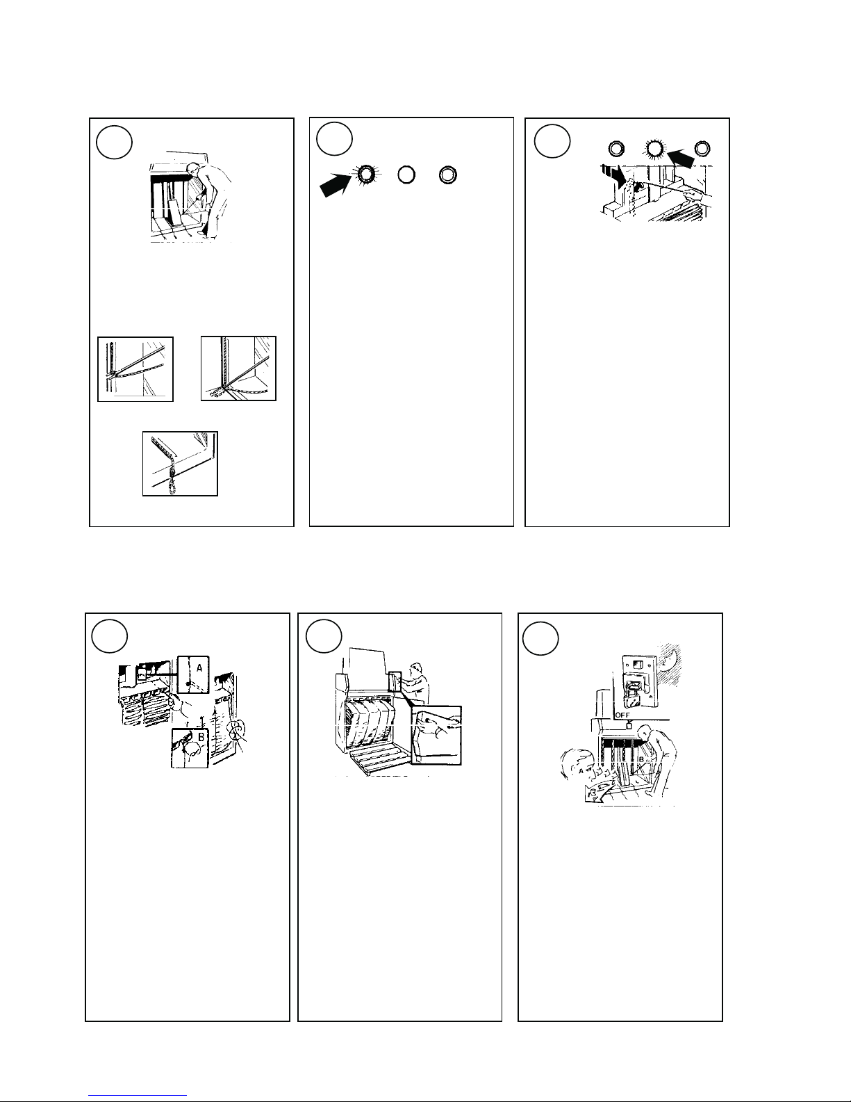
OPERATING INSTRUCTION
1
4
5 6
A
B
C
2
3
Place baling cord by
using special tool.
Put wate into the chamber
and press the start button.
Use speciala tool for baling
cord and pull it throught the
press plate, tie and cut of
the cord.
Make sure that the ejection
plate is free from wate,
place the baling cord in
postion and close the door.
Press the start button, Turn
of the main swich when the
baler is not used.
Stand behind the door and
press the two buttons.
Automatic stop at full bale.
The machine will stop automatically when full and yellow
lamp comes on. Open the
door make sure that the
ejector arm is in correct
position (forward). BALING
MUST BE DONE WITHIN 15
MIN.
Manuell stop at full bale.
By pushing in and turning the
yellow lamp switch the
machine will stop under full
pressure and baling can be
done by opening the door.
BALING
LAMP
Max
15 min
START
BALING
STOP
Page 9
9
8020
TECHNICAL DATA
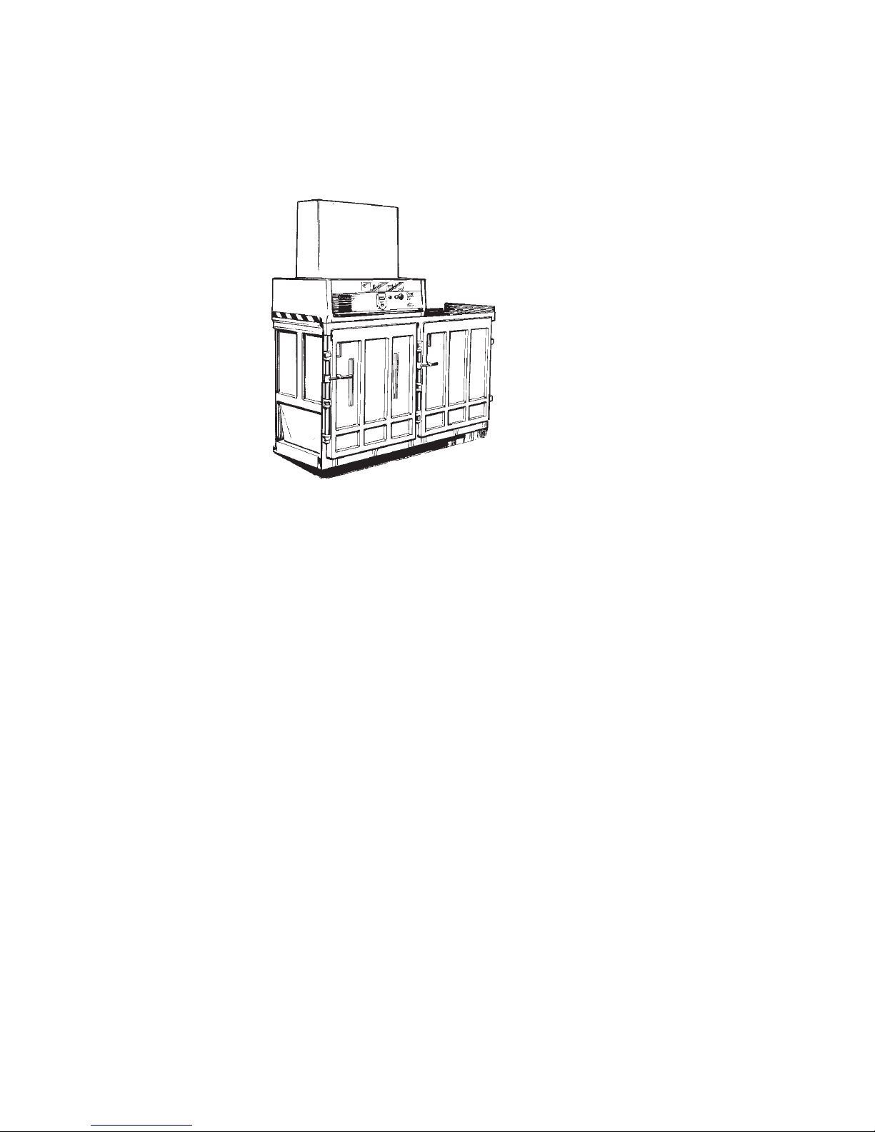
Overall length 2,43 m
Overall width 1,11 m
Overall height 2,36 m
Electrical system
Working voltage 220 / 380 / 415 V 3-phase
50 Hz 16 A
Control voltage 220 / 240 V
Motor rating 3 hp ( 2,2 kW)
Pressing force 16-20 ton ( 2,6 kg / cm2)
Cycle time 30 seconds
Oil volume 32 l
Page 10
10
11
8020
TRANSPORT
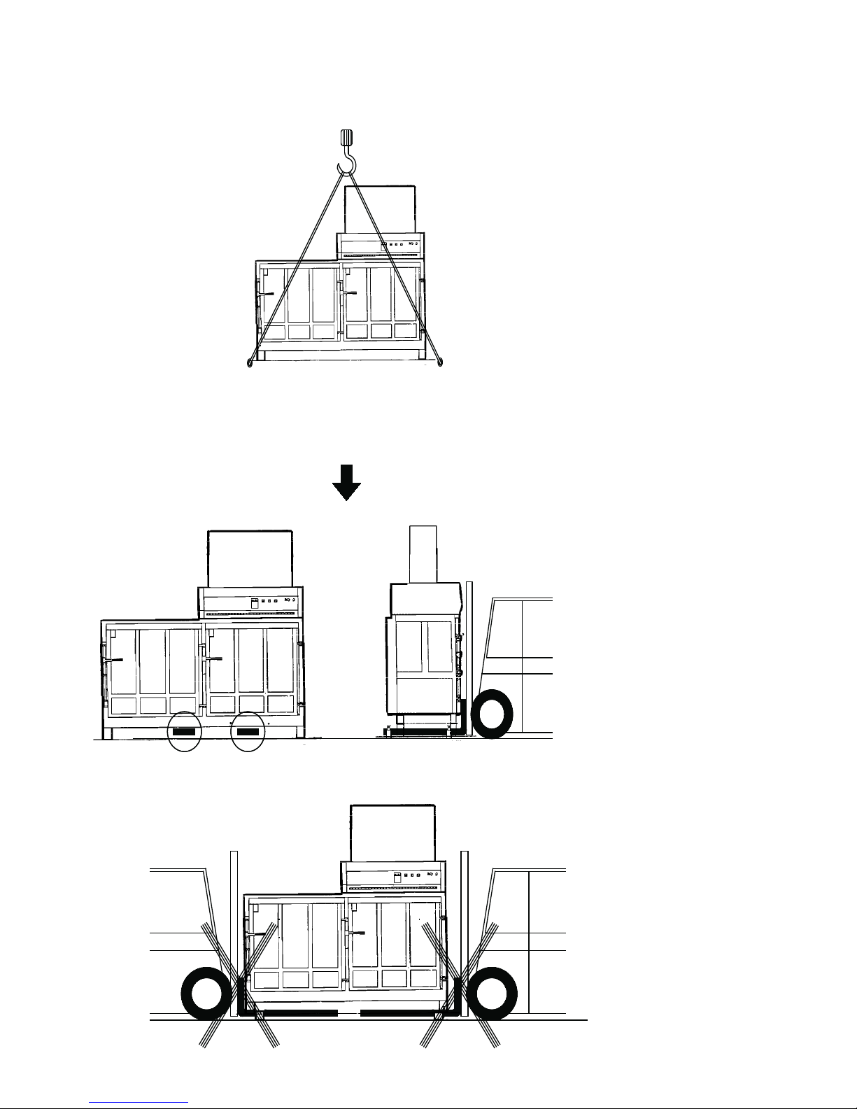
1500 kg
Page 11
11
8020
INSPECTION& MAINTENANCE
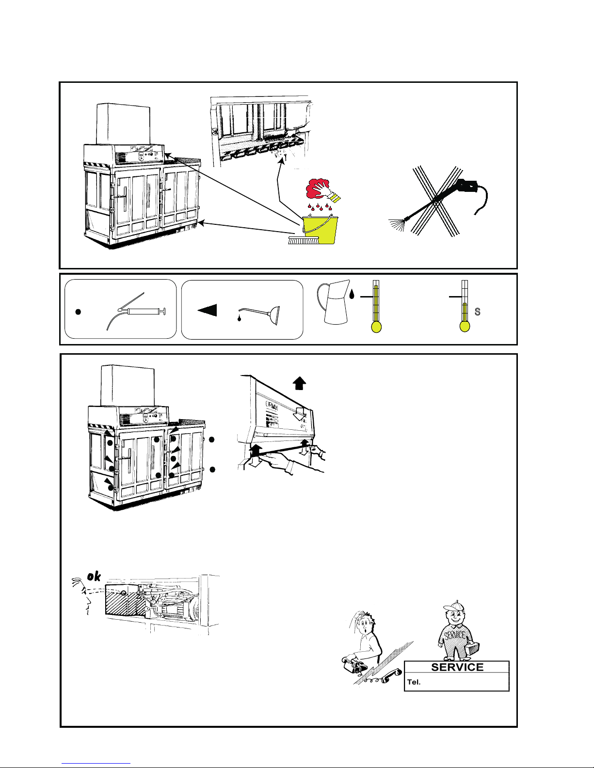
Hydraulic oil
VG 32-68
-0 C
o
+0 C
LE 6520
S
AE 5-20
SAE 20
=
=
SAFETY CHECK
When you have remove the bale from the
machine xlose the door. Start the machine.
When the press plate goes down, open the
door to the chamber.
The machine should stop and the press plate
can only go upwards when pressing the bale
buttons on the side of the machine. CONTACT
AUTORIZED SEVICE PRESONAL IF THE
SAFETY SWITCHES DOES NOT
WORK.When the press plate is going upwards
activate the safety bar ( see picture). When the
bar is activated the machine stops.
IF THE MACHINE DOES NOT STOP WHEN
THE SAFETY BAR IS ACTIVATED CONTACT
AUTHORIZED SERVICE PERSONAL.
Page 12
12
13
8020
INSTRUCTION FOR INSTALLATION
Page 13

13
DECLARATION OF INCORPORATION
(Directive 89/392/EEC, Art. 4.2 and Annex II, sub B)
We AB ORWAK
Box 58
S-576 22 Sävsjö, Sweden
tel. 46-382-15700 / telefax 46-382-10607
Herewith declares that the
machinery: press unit
type: 4908020-81
is intended to be incorporated into
complete machinery: baling press
type: 4908020-06 / -07 / -08
It is not allowed to put the machinery into service until the complete machinery into
which it is to be incorporated has been declared to be in conformity with all for the
complete machinery applicable Directives.
Sävsjö 1996-06-17
.........................................
Kenneth Gustavsson
Chief designer
Page 14
 Loading...