

Page 1
Attention! Reliability and life of the product are provided not only by the quality of product itself,
but also by the compliance with operating modes and conditions, therefore, meeting the
requirements of this document is mandatory.
“Lind-EM” Proximity Identification Card Reader
Operating Manual
ORTUS Group
Product Compatibility Table
Control Panel “Lun-11”, “Lun-11 mod.2”,
“Lun-9T”, “Lun-7T”
Version
GSM Control Panel Configuration
Software
Configurator 11
Version
Central Monitoring Station “Orlan-M11” modules-
based Orlan
Version
Page 2

Table of contents
1. Purpose............................................................................................................................................................................. 3
2. Design............................................................................................................................................................................... 3
3. Controls and indicators............................................................................................................................................... 4
4. Arming............................................................................................................................................................................... 5
5. Disarming......................................................................................................................................................................... 6
6. Fire alarm reset (“Lun-11”/”Lun-11mod.2”)..........................................................................................................6
7. Maintenance.................................................................................................................................................................... 7
8. Operating conditions....................................................................................................................................................7
9. Storage.............................................................................................................................................................................. 7
10. Transportation.............................................................................................................................................................. 7
11. Disposal.......................................................................................................................................................................... 7
12. Appendix 1. Connection diagrams......................................................................................................................... 8
13. Appendix 2. Warranty Service Regulations....................................................................................................... 11
АДМА.425713.005 РЭ Rev. en_3 2
Page 3
1. Purpose
“Lind-EM” Proximity Identification Card Reader (hereinafter referred to as “reader”) is designed
to control “Lun-11”, “Lun-11 mod.2”, “Lun-9T” and “Lun-7T” Control Panel and display their status.
The reader operates with proximity cards/keyfobs of “EM-Marine” standard on a frequency of
125 kHz at the distance of 3...8 cm.
Attention! Product is not equipped with built-in cameras and microphones, devices
and units for hidden video and audio recording.
2. Design
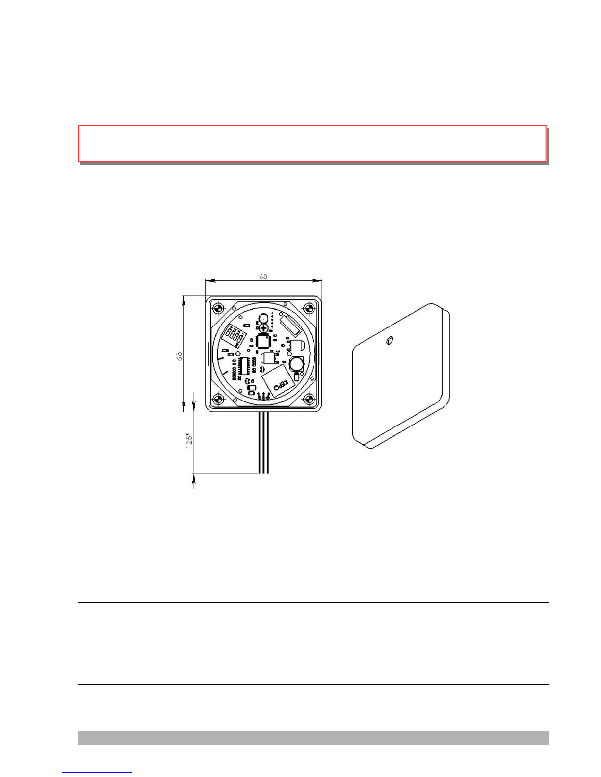
The reader is a compact device placed in a plastic housing, designed for installation on a flat
surface (eg wall). To connect to the alarm system it has three multi-colored insulated wires
(Figure 1).
Figure 1. “Lind-EM” reader
Wires assignment described in Table 1, connection diagrams to Control Panels see at
Figures 2, 3, 4.
Table 1. "Lind-EM" reader's wires assignement
Title Wire colour Assignment
GND Black Common terminal (–)
BUS White Interface to Control Panel:
TAN “Lun-11”/”Lun-11mod.2”
BUS “Lun-9T”/”Lun-9P”
TM “Lun-7T”/”Lun-73T”
+12V Red Power-up input (+)
АДМА.425713.005 РЭ Rev. en_3 3
Page 4
There are up to 14 readers may connected to the "Lun-11" / "Lun-11 mod.2» Control Panel and
only one reader – to the "Lun-9T", "Lun-7T" Control Panels.
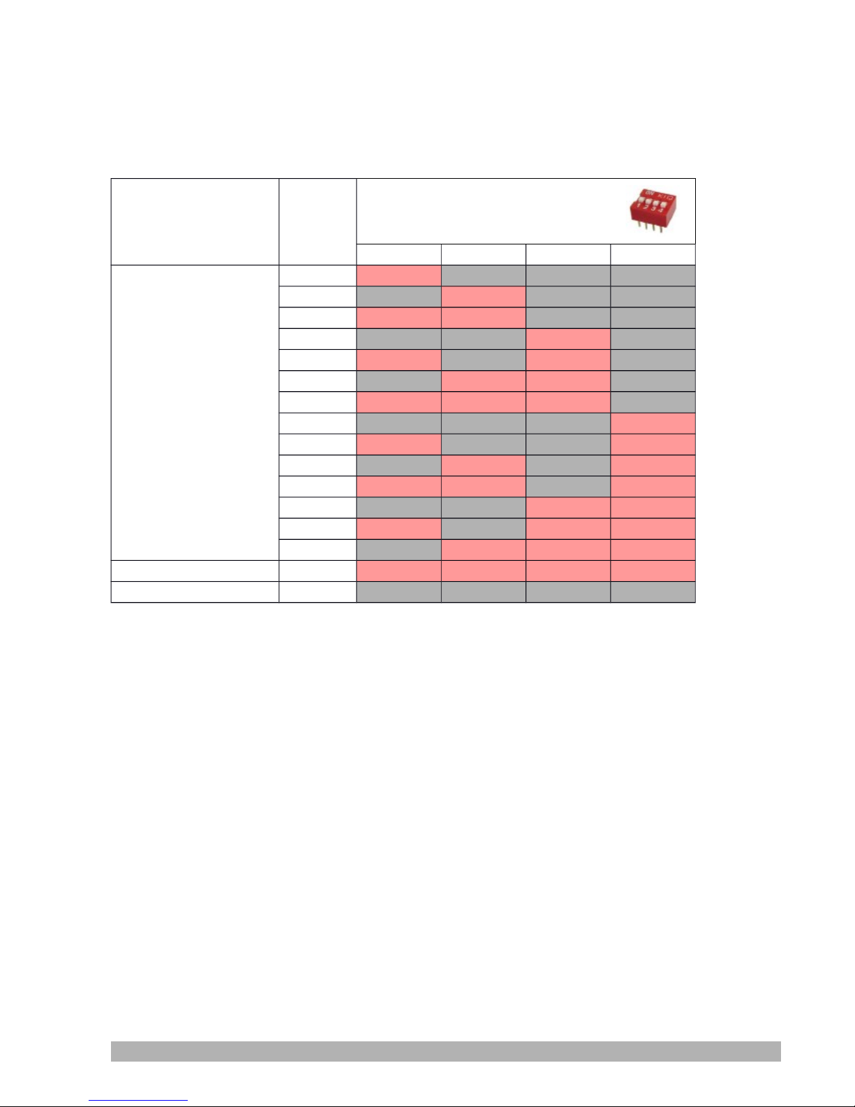
Control Panel's type and reader's address on the bus shall be set for correct operation using
DIP-switches located inside the reader in accordance with Table 2.
Table 2. Reader's DIP-switches settings
Control Panel
Reader's
address
DIP-switches settings
(1=ON; 0=OFF)
1 2 3 4
“Lun-11”/
“Lun-11mod.2”
1 1 0 0 0
2 0 1 0 0
3 1 1 0 0
4 0 0 1 0
5 1 0 1 0
6 0 1 1 0
7 1 1 1 0
8 0 0 0 1
9 1 0 0 1
10 0 1 0 1
11 1 1 0 1
12 0 0 1 1
13 1 0 1 1
14 0 1 1 1
“Lun-9T”/”Lun-9P” – 1 1 1 1
“Lun-7T”/”Lun-73T” – 0 0 0 0
3. Controls and indicators
Multifunctional LED is on the reader's front panel (see Figure 1) showing the Control Panel's
status (lit when armed / goes off upon disarming). In "Lun-11" / "Lun-11mod2" working mode and in
the absence of communication with the Control Panel for more than 3 seconds, the LED flashes
with a frequency of 10 Hz (10 times per second).
When you try to arming Control Panel when some zones is violated, LED indicates the number
of the first violated zone (but no more than 8 zones) by corresponding number of flashes. If the
number of the first violated zone in the group is more than eight, the number of flashes will always
be nine (9).
Reader contains buzzer that beep (1 Hz frequency) when Control Panel arming for warns to
leave the room.
At the beginning of the disarming process buzzer's sound reminds to disarm Control Panel by
identification card. Beep switched off when user will approach legal identification card/fob to the
reader.
There is tamper button inside the reader. It is triggered when removing the cover. Tamper
status is transmitted to CSN when reader connected to "Lun-11"/"Lun-11mod.2" Control Panels.
АДМА.425713.005 РЭ Rev. en_3 4
Page 5
4. Arming
1. You should tightly close all room doors and windows to arming Control Panel.
Attention! You can't to arm some group if at least one detector (zone) in this group is
at the "alarm" state.
If reader is within range of the optical sensor, you should stop moving for a few seconds
before PIR goes to normal state.
2. Making sure that all zones are in normal state should bring allowed identification card or
key fob to the reader closely. At the time of recognition of the card/fob reader beeps (for the
"Lun-7T" Control Panel – without sound).
If all zones are in normal state, the arming process starts with arming exit delay countdown
short beeps (during the all time out). If the identification card or key fob is not recorded in
the Control Panel's configuration, then a specific sound will be given and arming process
will not start (for the "Lun-7T" Control Panel – without sound).
You should to leave the room immediately after turning on the reader's red LED – during the
exit delay countdown beeps (this time out should be set during configuration previously).
Attention! The LED displays the status of the one group only (previously selected
during configuration process).
Triggering sensors for "delayed" and "interior delayed" zones will not be alarm during the
exit delay countdown.
You can monitor the arming process by watching the remote LED from outside of the
object.
Attention! If you can not leave the object before the time out end and siren on should
bring dentification card or key fob to the reader. Siren is turned off and the arming will be
canceled. You may arming repeat again in a few seconds.
If the remote LED lights continuously, it means that:
● Group (object) armed;
● Arming message sent to the CMS and confirmation received by Control Panel.
Attention! Remote LED flashing shall not exceed 180 seconds. Unless this time is
exceeded, or turn off the indicator, then the group (object) arming not accepted for any
reason.
In this case, check the following:
● Signal level in the remote antenna installation place.
● CMS phone numbers that are stored in Control Panel's memory during configuration.
АДМА.425713.005 РЭ Rev. en_3 5
Page 6

5. Disarming
1. You should enter the armed room through the front door. There are a time out since opening
the front door to an alarm on (time out configurable).
2. You should go to the reader and bring legal identification card/fob to him before time out
end. As the card/fob recognized, reader's buzzer will sound a short beep (for "Lun-7T" Control
Panel – without sound). Then object will be disarmed with a series of short beeps (for "Lun7T" Control Panel – without sound) and LED on the reader will go off. If the card/fob is not
registered in the Control Panel, then disarming is impossible. Buzzer sounds long
intermittent signal (for "Lun-7T" Control Panel – without sound).
Attention! If the time out ends but the object (group) is not disarm and the siren is on
– you should bring allowed identification card or key fob to the reader closely. Siren will
be off.
6. Fire alarm reset (“Lun-11”/”Lun-11mod.2”)
To reset the fire alarm you should bring allowed identification card/fob to the reader closely.
If a fire alarm on when a group armed – the first touch to reader resets the fire alarm, the second –
disarming.
АДМА.425713.005 РЭ Rev. en_3 6
Page 7

7. Maintenance
This product does not require any maintenance.
8. Operating conditions
The device shall be used at the temperature of –5°С to +40°С and relative humidity of 5% to
85%.
9. Storage
1. Product storage in terms of the climate impact shall be under conditions 2 according to
GOST 15150. Storage temperature shall be of -50°C...+40°C at the relative humidity of
5% up to 98%.
2. During handling operations, transportation and storage in warehouses, boxes with the
product shall not be exposed to sharp bows. Stacking and fixing of the boxes to the
transporter shall not include their movement.
3. Product shall be stored in the manufacturer's package.
10. Transportation
1. Product transportation shall be carried out in the manufacturer's package.
2. Product is allowed to be transported by all types of enclosed transporters, subject to
observing the shipping rules applicable for each type of transport.
3. Product transportation requirements in the terms of the impact of mechanical factors
shall be Group 2 according to GOST 12997.
4. Product transportation in terms of the climate impact shall be under conditions 5
according to GOST 15150. Transportation temperature shall be of -50°C to +50°C at the
relative humidity of 5% up to 98%.
11. Disposal
Product disposal shall be carried out according to electronic household appliance disposal
rules established by the legislation of the State, where the product is operated.
АДМА.425713.005 РЭ Rev. en_3 7
Page 8
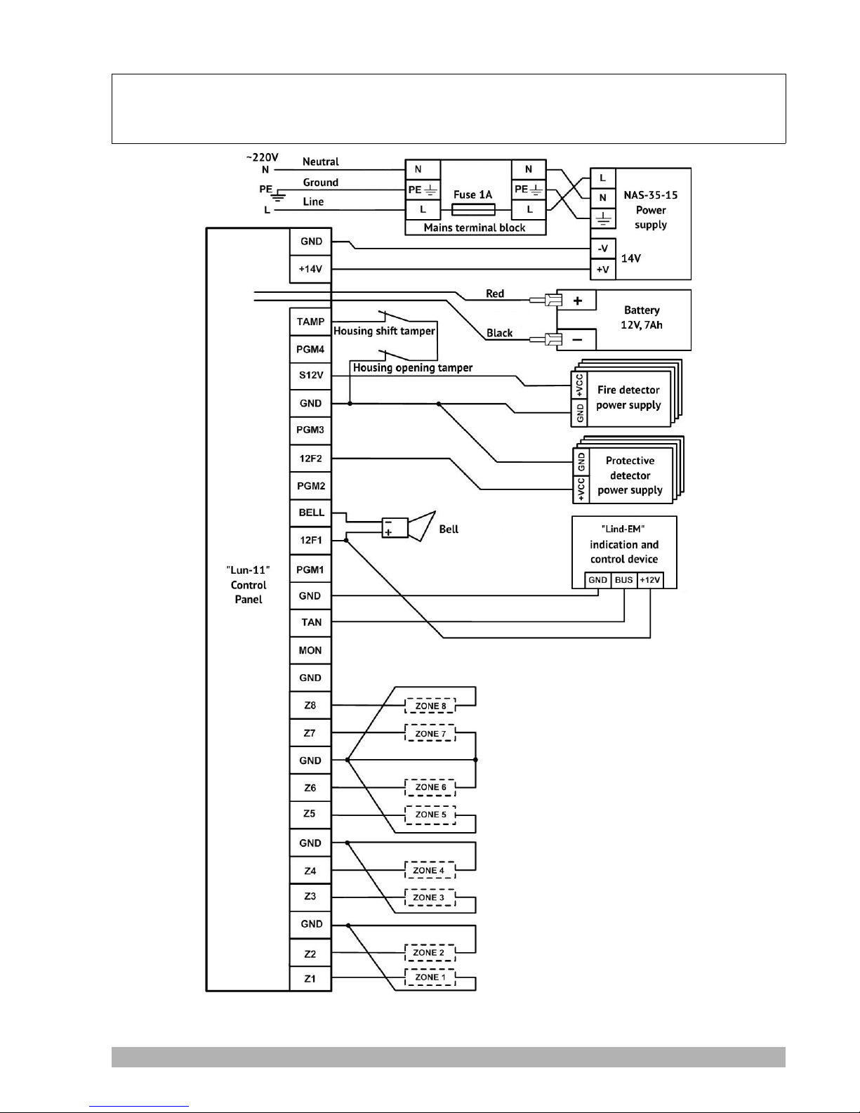
12. Appendix 1. Connection diagrams
Attention! Adherence to this connection diagram is mandatory. Failure to comply with this
requirement can lead to breakdown of the device, and consequently, to impossibility of
performance of the warranty liabilities.
Figure 2. Diagram of connection “Lind-EM” ICD to “Lun-11” Control Panel
АДМА.425713.005 РЭ Rev. en_3 8
Page 9
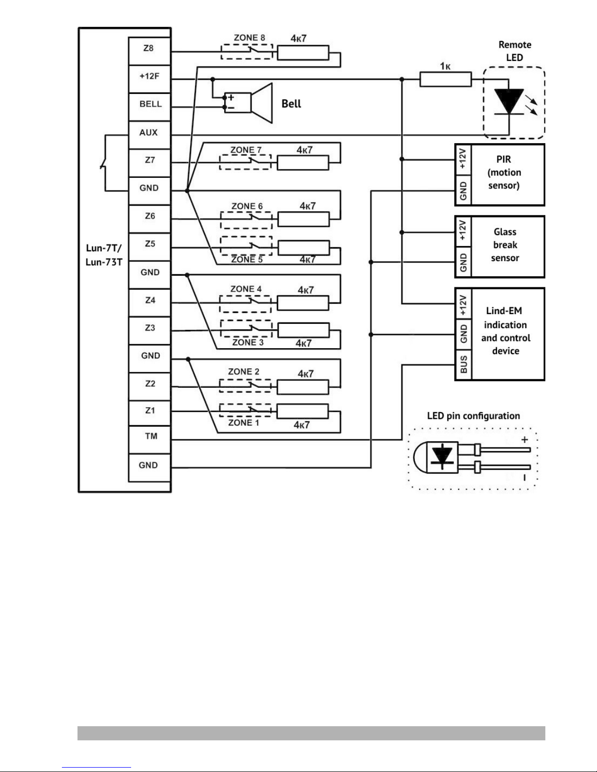
Figure 3. Diagram of connection “Lind-EM” ICD to “Lun-7T”/”Lun-73T” Control Panel
АДМА.425713.005 РЭ Rev. en_3 9
Page 10
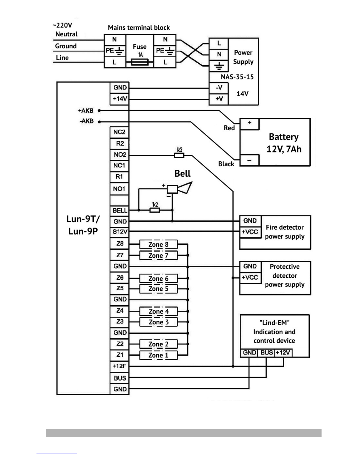
Figure 4. Diagram of connection “Lind-EM” ICD to “Lun-9T”/”Lun-9P” Control Panel
АДМА.425713.005 РЭ Rev. en_3 10
Page 11

13. Appendix 2. Warranty Service Regulations
1. Manufacturer warrants and guarantees the absence of Equipment manufacturing defects and faults and shall
be responsible for the warranty obligations in accordance with the laws of Ukraine.
2. Warranty period is calculated from the date of purchase of the device from the authorized dealer.
3. During warranty period, the Manufacturer shall, at its own cost, remedy defects of the Equipment by its repair
or replacement to the similar Equipment, provided that the defect has arisen through the Manufacturer’s fault.
The device provided for replacement can be new or restored, but in any case, the Manufacturer guarantees that
its performance will be the same as of the replaced one.
4. Execution by the Manufacturer of its warranty obligation on the repair of the damaged Equipment entails an
increase in the warranty period for the time of repair of the Equipment.
5. If the warranty period expires less than one month after repair of the device, the additional Warranty for a
period of 30 days from the date of repair completion shall be established for this device.
6. Manufacturer shall not be responsible for the compatibility of its Software with any hardware or software
supplied by other manufacturers, unless otherwise specified in the Documents attached.
7. Under no circumstances shall the Manufacturer be responsible for any damages, including loss of data, loss of
profits or other incidental, consequential or indirect damages, arising from inadequate installation,
maintenance, operation, or performance, failure and temporary malfunction of the Equipment.
8. Manufacturer shall not be liable under the Warranty, if the test and/or analysis conducted by the Manufacturer
shows that the product has no claimed defect, or it that this defect is the result of violation of the installation
rules or operation conditions, as well as of any actions to make the device perform the functions not stated by
the Manufacturer.
9. Warranty terms do not provide cleaning and preventive maintenance of the Equipment by the Manufacturer.
10. Manufacturer shall not be liable for Equipment defects and faults, resulting from:
a. non-compliance with the transportation rules and storage conditions, technical requirements for the
arrangement and operation;
b. improper actions, unintended use of the Equipment, non-compliance with the operating instructions;
c. mechanical effects;
d. force majeure (such as fire, flood, earthquake, etc.)
WARRANTY SHALL NOT COVER:
● counterfeit products purchased under the Manufacturer’s trademark ;
● failures caused by the environmental effects (rain, snow, hail, storm, etc.), force majeure (fire, flood,
earthquake, etc.) or by impact of accidental external factors (voltage surges in the electrical power line, etc.);
● failures caused by violation of transportation, storage or operation rules or by inadequate installation;
● failures followed by repair of the Equipment or its modification by persons not authorized by the
Manufacturer;
● damages caused by intrusion of foreign items, materials, liquids, insects, etc. inside the Equipment;
● equipment with external defects (obvious mechanical damages, cracks, chips on the housing and inside the
device, broken antenna or connector pins).
Manufacturer:
ORTUS Group
5624 California st,
San Francisco, CA 94121, USA
Tel.:+1 650 240 27 62
mail: [email protected]
http://www. ortus.io
АДМА.425713.005 РЭ Rev. en_3 11
 Loading...