

Ortopedia Impuls-System, Impuls 1, Impuls 1 Euro, Impuls 1 Vario, Impuls 2 Operating Manual
...
Operating Manual
FOLDING WHEELCHAIR
Impuls-System
S T A Y M O B I L E
1

Table of Contents
1. Introduction .................................................................................................................. 6
2. Handling the wheelchair .............................................................................................. 7
2.1 Appli cation ........................................................................................................................... 7
2.2 Performance .......................................................................................................................... 8
2.3 Safety information ................................................................................................................. 8
2.4 Additional user/safety information ..................................................................................... 9
2.4.1 User information .................................................................................................. 10
2.5 Folding/unfolding ............................................................................................................... 15
2.5.1 Folding the wheelchair ........................................................................................ 15
2.5.2 Unfolding the wheelchair .................................................................................... 15
2.6 Transportation ..................................................................................................................... 16
3. Overview...................................................................................................................... 16
3.1 IMPULS 1............................................................................................................................. 17
3.2 IMPULS 2-4 ......................................................................................................................... 18
3.2a IMPULS XX ........................................................................................................................ 19
3.3 Components ....................................................................................................................... 20
3.3.1 Seat band ............................................................................................................ 20
3.3.1.1 Seat band XX ...................................................................................... 20
3.3.1.2 Seat cushion ........................................................................................ 20
3.3.1.3 Fixed seat on the Impuls XX ............................................................... 20
3.3.2 Backrest ................................................................................................................ 21
3.3.2.1 Backrest with angle adjustment ......................................................... 21
3.3.2.2 Back band, standard ........................................................................... 22
3.3.2.3 Back, ORTOFLEX .................................................................................. 22
3.3.2.4 Backrest with 30° angle adjustment ................................................... 23
3.3.2.5 Height-adjustable sliding handles ..................................................... 24
3.3.2.6 Back stiffening bar .............................................................................. 24
3.3.3 Armrest ................................................................................................................ 25
3.3.3.1 Clothes guard ..................................................................................... 25
3.3.3.2 Non-locking armrest ........................................................................... 25
3.3.3.3 Armrest with double locking .............................................................. 26
3.3.3.4 Hei ght-ad justab le armr est ................................................................. 26
3.3.4 Leg supports ........................................................................................................ 27
3.3.4.1 Calf support ........................................................................................ 27
3.3.4.2 Folding up the foot plates .................................................................. 27
3.3.4.3 Swivelling leg supports aside ............................................................. 28
3.3.4.4 Removal of leg supports ..................................................................... 29
3.3.4.5 Attachment of leg supports ................................................................ 29
3.3.4.6 Positioning of foot plates .................................................................... 30
3.3.4.7 Adjustment of foot plate angle .......................................................... 30
3.3.4.8 Adjustment of foot plate height ......................................................... 31
3.3.4.9 Foot board .......................................................................................... 31
3.3.4.10 Leg support with angle adjustment (774-1) ...................................... 32
3.3.4.11 Leg support with angle adjustment and
length compensation (774-2 AL) ........................................................ 33
32

3.3.5 Driving wheels ..................................................................................................... 34
3.3.5.1 Full float ing axle ................................................................................. 34
3.3.5.2 Hand wheels ....................................................................................... 35
3.3.6 Brakes................................................................................................................... 35
3.3.6.1 Safety information .............................................................................. 35
3.3.6.2 Toggle joint brake .............................................................................. 36
3.3.6.3 Drum brake ........................................................................................ 36
3.3.6.4 Service brake function ........................................................................ 36
3.3.6.5 Locking the brake ............................................................................... 37
3.3.6.6 Releasing the brake ............................................................................ 37
3.3.6.7 Changing or replacing driving wheels ............................................... 37
3.3.6.8 Drum brake for carers ......................................................................... 38
3.3.6.9 Adjustment of toggle joint brake ....................................................... 38
3.3.7 Swivel wheels ...................................................................................................... 39
3.3.8 Tyres ..................................................................................................................... 39
4. Individual customisation ........................................................................................... 40
4.1 Seat height/seat inclination ............................................................................................. 40
4.1.1 Driving wheel position ......................................................................................... 41
4.1.2 Swivel wheel position .......................................................................................... 42
4.2 Wheel camber .................................................................................................................. 42
5. Optional accessories ................................................................................................... 43
5.1 Lap belt ............................................................................................................................ 43
5.1.1 Fastening lap belt ................................................................................................ 43
5.1.2 Setting belt length .............................................................................................. 43
5.2 Stabilisers ......................................................................................................................... 44
5.2.1 Swivelling the stabilisers ..................................................................................... 44
5.2.2 Setting the height ................................................................................................ 45
5.2.3 Correct stabiliser length: ..................................................................................... 45
5.3 Tread cap ............................................................................................................................ 45
5.3.1 Setting the height ................................................................................................ 45
5.4 Transit wheels...................................................................................................................... 46
5.4.1 Setting the height ................................................................................................ 46
5.4.2 Removing driving wheels ..................................................................................... 46
5.4.3 Locking brake ....................................................................................................... 46
5.5 Spoke guard ..................................................................................................................... 47
5.5.1 Removal ............................................................................................................... 47
5.5.2 Installation ...........................................................................................................47
5.6 Brake lever extension ....................................................................................................... 47
5.7 Tray................................................................................................................................... 48
5.7.1 Standard tray ....................................................................................................... 48
5.7.2 8001 tray .............................................................................................................. 48
6. Care and maintenance ................................................................................................ 4 9
6.1 Care ................................................................................................................................. 49
6.2 Maintenance .................................................................................................................... 50
6.2.1 Tools ..................................................................................................................... 50
6.2.2 Maintenance instructions ..................................................................................... 51
6.2.3 Punctures.............................................................................................................. 52
6.3 Repairs.............................................................................................................................. 53
6.4 Customer service .............................................................................................................. 53
6.5 Spare parts .......................................................................................................................53
7. Technical data ............................................................................................................. 54
7.1 Impuls 1 model ................................................................................................................ 54
7.2 Impuls 1 Euro model ........................................................................................................ 55
7.3 Impuls 1 Vario model ....................................................................................................... 56
7.4 Impuls 2 model ................................................................................................................ 57
7.5 Impuls 3 model ................................................................................................................ 58
7.6 Impuls 4 model ................................................................................................................ 59
7.7 Impuls XX model ..............................................................................................................60
9. Guarantee .................................................................................................................... 61
Notes: ....................................................................................................................................... 62
54

1. Introduction
2. Handling the wheelchair
Thank you choosing a wheelchair from the
IMPULS model range.
With its many design versions and accessories, the IMPULS wheelchair system can
be adapted to suit your varying clinical
needs.
Like any other vehicle, a wheelchair is a
technical aid. It requires explanations for
use and a degree of maintenance. It also
has hidden dangers that may appear if it
is used incorrectly. It is therefore important to learn how to handle it correctly .
These instructions are intended for use in
conjunction with the booklet "Safety Information for Mechanical Wheelchairs",
to help you to familiarise yourself with the
operation of the wheelchair and to prevent accidents.
Children should read these instructions
and the booklet "Safety Information for
Mechanical Wheelchairs" with their parents, guardian or carer before venturing
out for the first time.
☞ Note:
Please note that the equipment versions illustrated may differ from your
model.
2.1 Application
The IMPULS 1 wheelchair is a standard
lightweight wheelchair with a fixed driving wheel position.
IMPULS 2-4 models are activity wheelchairs, which can be adapted to suit the
corresponding requirements of respective users.
The Impuls XX wide wheelchair is for
heavier users weighing up to max. 160
kg.
The Impuls Postura wheelchair offers a
padded backrest with angle adjustment
and a padded seat, which can also be
adjusted in depth.
IMPULS System wheelchairs are designed for daily use, both indoors and
outdoors, for work or for leisure. For the
experienced user, the IMPULS System
wheelchair offers possible settings for
active performance with high manoeuvrability.
Before being used for the first time, the
wheelchair should be adjusted by your
ORTOPEDIA dealer . The adaptation will
take into account the driving experience, the physical limits of the user and
the main place of use of the wheelchair.
Warning:
Setting or adjustment should only be
carried out by an authorised ORTO-
!
PEDIA dealer.
76

2.2 Performance
Optimisation of the performance characteristics of the IMPULS System wheelchair to fit your personal circumstances
should be discussed with your
ORTOPEDIA dealer or physician.
The adaptability of the wheelchair offers you a high degree of comfort and
safety in all areas of life, e.g. family , work
or leisure.
2.3 Safety information
▲ Please follow the safety information
for mechanical wheelchairs contained in the relevant booklet.
▲ A direct change of movement to the
opposite direction, e.g. from reverse
to forward movement without involving a steering action, causes full braking if the swivel wheels are moving
inwards at the same time.
▲ The use of a safety belt prevents the
user from falling out of the wheelchair.
2.4 Additional user/
safety information
▲ When travelling in public thorough-
fares, clean passive lighting must be
used!
▲ Do not throw or drop parts belong-
ing to the wheelchair!– Removable
parts such as armrests and leg supports should be handled correctly to
ensure lasting performance. To guarantee their function.
▲ Before moving off, check that remov-
able parts such as armrests and leg
supports, are locked correctly in position. Drive wheels with defective
linchpin (quick-fit) axles can detach
from the wheelchair during the drive.
▲ The addition or removal of accesso-
ries/components will cause the dimensions and weight of the wheelchair to change. This can also result
in a change in performance.
▲ Never leave children/young persons
unsupervised in wheelchairs.
▲ For smaller obstacles, e.g. small
ledges/slopes, always move slowly
and at a right angle (90°) to the obstacle, until the swivel wheels are almost touching the obstacle. Briefly
stop the wheelchair and then drive
over the obstacle.
▲ Give a wide berth to grooves, rails,
manhole covers or similar sources of
danger. If not possible, cross such
obstacles at a right-angle (90°).
▲ Maintain a safe distance from steep
inclines, staircases and obstacles to
allow sufficient space to react, brake
and turn.
▲ Always reduce speed before a bend.
A sharper curve requires a lower
speed. Never lean outwards in a
curve.
98
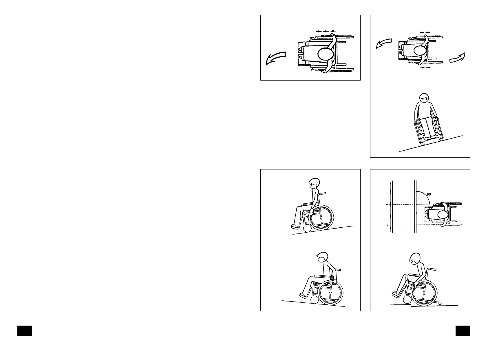
Negotiating a bend
Turning
▲ Tyres are made of a rubber com-
pound and may leave marks on some
surfaces (e.g. plastic, wooden or parquet flooring, rugs, carpets) that are
hard to remove or even permanent.
▲ To prevent damage from corrosion,
do not use the wheelchair in damp
conditions, do not travel through
puddles or water and do not expose
it to continuous rain.
Recommendations for travelling
at dusk or at night
▲ During periods of darkness, avoid
roads and cycle paths as far as possible. Wear light-coloured clothing that
can be seen at a distance.
2.4.1 User information
The following pages give general information and suggestions for handling
and use of the wheelchair in everyday
situations. Make yourself thoroughly and
carefully familiar with the wheelchair.
New driving situations must be practised
with the support of a helper.
▲ Before changing from one seating
option to another, or before leaving
or entering the wheelchair, always
lock the brakes to prevent the wheelchair from rolling away.
▲ T o lean the upper body well forward,
manoeuvre the wheelchair backwards until the swivel wheels face
forwards for increased stability.
Turning on a slope
Driving downhill Approaching an obstacle
Driving uphill
Obstacle crossing
1110
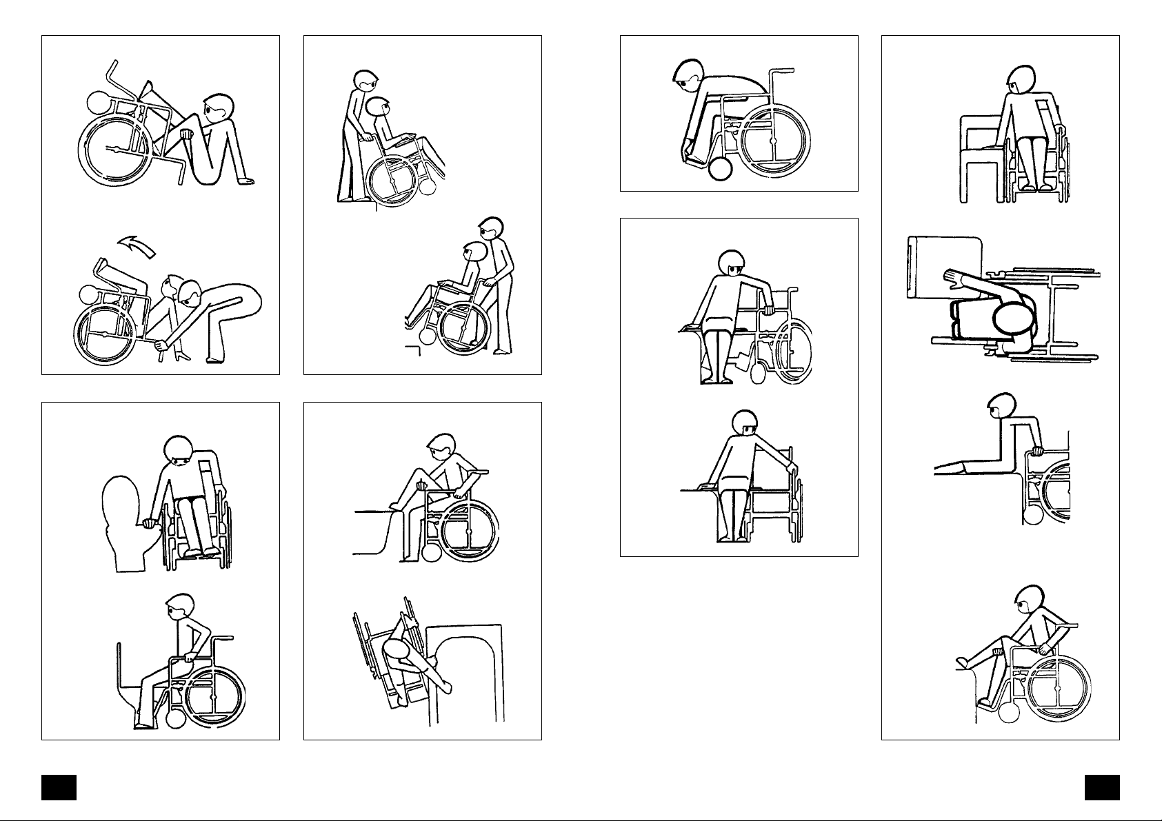
Climbing in
Crossing drops/steps
Steering wheels forwards = safe stability Transfer
Bringing the wheelchair upright
Toilet use Climbing into the bath
Transfer with sliding board
Lowering the legs
1312
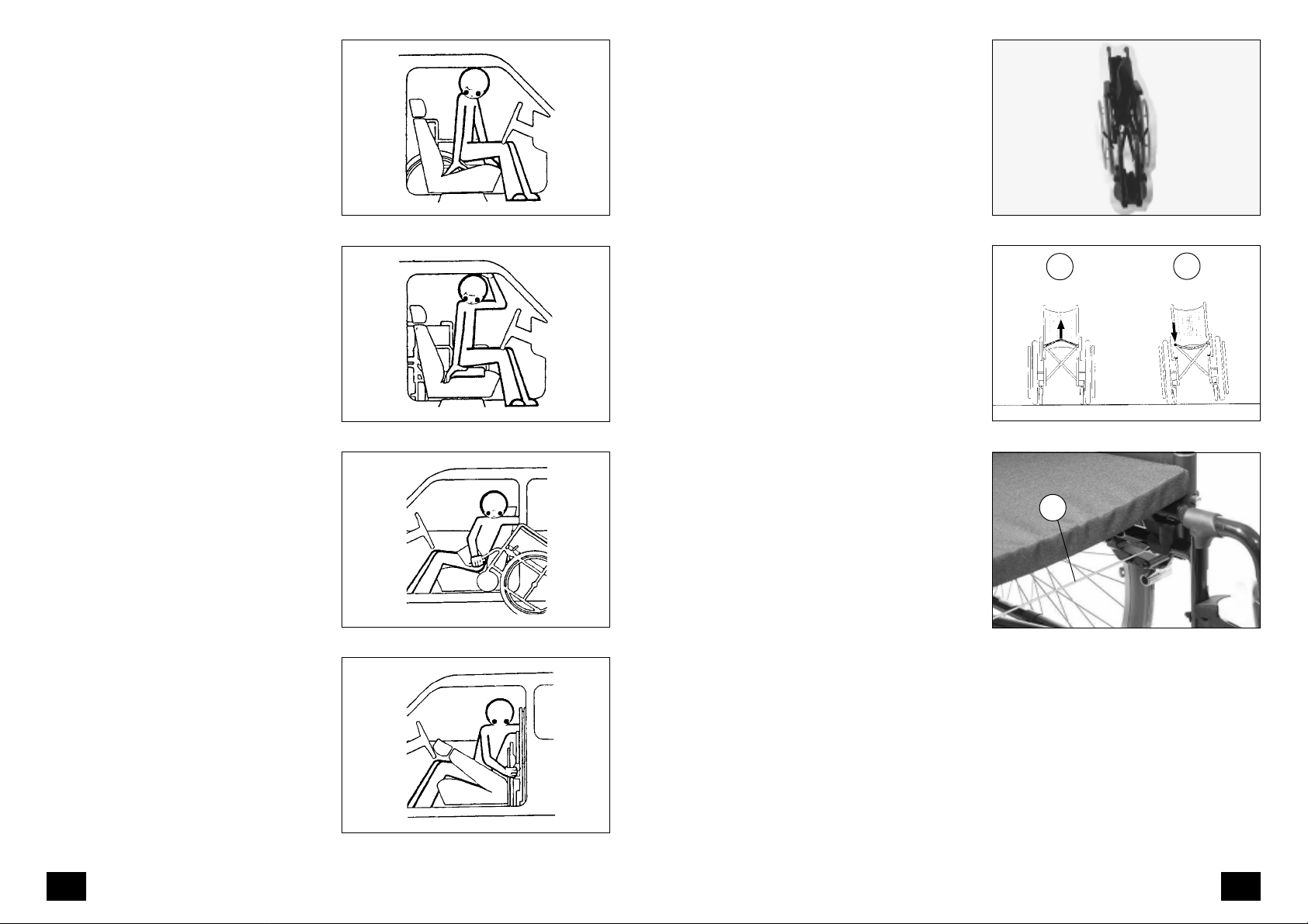
Wheelchair and the car
2.5 Folding/unfolding
Move the wheelchair parallel and adjacent to the driver or passenger seat.
Detach the legrests and the armrests in
order to reduce the wheelchair weight
and make the lifting into the car easier.
Lock the brakes to prevent the wheelchair from moving. The door frame can
be used for holding or the seat for support during the transfer into the car.
A sliding board can be used to bridge
the gap between the wheelchair and
the car seat. The possibilities here depend on the type of vehicle, the height
of the car seat and the height of the
wheelchair seat.
Unlock the brakes of the wheelchair
before its loading. The personal possibilities and the spaciousness of the vehicle determine whether the wheelchair
is now pulled into the car from the driver's seat or the front passenger seat.
Transferring to the car
Transfer into the car
2.5.1 Folding the wheelchair
To fold the wheelchair (Fig. 1), fold up
the foot plates of the leg supports or
remove the leg supports. Press the centre of the chest belt backwards. Lift the
back and the front of the seat cover upwards from the centre (Fig. 2/
➀).
2.5.2 Unfolding the wheelchair
To unfold the wheelchair, tilt it slightly
to one side. On the side which is standing firm on the ground, push the seat
tube downwards until it reaches its limit
(Fig. 2/
➁).
☞ Note:
To do this, it may be necessary to
force both seat tubes into their final
position by hand.
The Bowden wire (Fig. 2.1/
vents the side frames being pushed
too far apart.
➀) pre-
1
1
2
1
2
Two-door cars usually cause fewer problems because the doors are usually
wider. In the case of a four-door car it
may be necessary for a helper to lift the
wheelchair into the passenger space or
the boot.
Loading the wheelchair
Loading the wheelchair
2.1
1514

2.6 Transportation
For storage or transportation purposes,
the wheelchair can be dismantled into
portable elements without the need for
tools.
Firstly the dimensions of the wheelchair
can be reduced by removing all removable parts. These include the leg supports and the armrests (arm pads are
not removable). Stabilisers (if present)
can be folded forwards.
The wheelchair can now be folded in
the normal way. In addition, driving
wheels equipped with full floating axles
can now also be removed.
During reassembly, ensure that each
part is correctly installed and securely
fastened. Check that components are
correctly positioned. Check the correct
seating of the components.
3. Overview
The overview shows the most important
components and operating elements of
the IMPULS System wheelchair .
The components shown in the following illustrations may not be identical to
those on your wheelchair. The location
and handling of the parts are nevertheless applicable to your IMPULS System
wheelchair model. Each time the wheelchair is assembled, or each time a setting is made, checks should be carried
out to ensure that the component in
question is fitted correctly and functioning properly.
3.1 IMPULS 1
The model shown in Fig. 3 is representative of all IMPULS standard lightweight
wheelchairs.
– IMPULS 1
– IMPULS 1 Euro
– IMPULS 1 V ario
1 Sliding handle
2 Backrest
3 Armrest
4 Seat band
5 Leg support lock
6 Legrest
7 Footrest
8 Calf support
9 Swivel wheel
10 Brake and locking mechanism
11 Drive wheel
12 Hand wheel
1 3 Full floating axle
1
13
12
3
23
11
10 9
4
5
6
7
8
1716
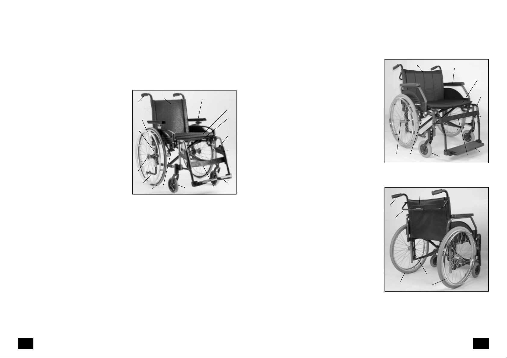
3.2 IMPULS 2-4
3.2a IMPULS XX
The model shown in Fig. 3 is representative of all IMPULS adaptable/activity
wheelchairs.
– IMPULS 2
– IMPULS 3 Hemi
– IMPULS 4
1 Sliding handle
2 Backrest
3 Armrest
4 Seat belt
4. 1 Seat cushion
5 Leg support lock
6 Legrest
7 Footrest
8 Calf support
9 Swivel wheel
10 Brake and locking mechanism
11 Drive wheel
12 Hand wheel
1 3 Full floating axle
1 4 Support wheel
15 Plate with punched holes for set-
ting variable seat height and wheel
position
1
15
13
14
3.1
12
2
10
The model shown in Fig. 3.2 and 3.3 is
representative of all IMPULS XX wheelchairs.
1 Sliding handle
2 Backrest
3 Armrest
3
4.1
4
5
6
7
911
8
4 Seat belt
5 Legrest
6 Leg support lock
7 Foot board
8 Calf support
9 Swivel wheel
10 Brake and locking mechanism
11 Drive wheel
12 Hand wheel
1 3 Full floating axle
14 Back stiffening bar
15 Plate with punched holes for set-
ting variable seat height and wheel
position
1 6 Sliding sleeve for dismantling back
stiffening bar
3.2
1
14
2
1013
16
3
4
5
6
7
9
8
3.3
11
15
12
1918
 Loading...