

Ortopedia Impuls-System, Impuls 1, Impuls 1 Euro, Impuls 1 Vario, Impuls 2 Operating Manual
...
Operating Manual
FOLDING WHEELCHAIR
Impuls-System
S T A Y M O B I L E
1

Table of Contents
1. Introduction .................................................................................................................. 6
2. Handling the wheelchair .............................................................................................. 7
2.1 Appli cation ........................................................................................................................... 7
2.2 Performance .......................................................................................................................... 8
2.3 Safety information ................................................................................................................. 8
2.4 Additional user/safety information ..................................................................................... 9
2.4.1 User information .................................................................................................. 10
2.5 Folding/unfolding ............................................................................................................... 15
2.5.1 Folding the wheelchair ........................................................................................ 15
2.5.2 Unfolding the wheelchair .................................................................................... 15
2.6 Transportation ..................................................................................................................... 16
3. Overview...................................................................................................................... 16
3.1 IMPULS 1............................................................................................................................. 17
3.2 IMPULS 2-4 ......................................................................................................................... 18
3.2a IMPULS XX ........................................................................................................................ 19
3.3 Components ....................................................................................................................... 20
3.3.1 Seat band ............................................................................................................ 20
3.3.1.1 Seat band XX ...................................................................................... 20
3.3.1.2 Seat cushion ........................................................................................ 20
3.3.1.3 Fixed seat on the Impuls XX ............................................................... 20
3.3.2 Backrest ................................................................................................................ 21
3.3.2.1 Backrest with angle adjustment ......................................................... 21
3.3.2.2 Back band, standard ........................................................................... 22
3.3.2.3 Back, ORTOFLEX .................................................................................. 22
3.3.2.4 Backrest with 30° angle adjustment ................................................... 23
3.3.2.5 Height-adjustable sliding handles ..................................................... 24
3.3.2.6 Back stiffening bar .............................................................................. 24
3.3.3 Armrest ................................................................................................................ 25
3.3.3.1 Clothes guard ..................................................................................... 25
3.3.3.2 Non-locking armrest ........................................................................... 25
3.3.3.3 Armrest with double locking .............................................................. 26
3.3.3.4 Hei ght-ad justab le armr est ................................................................. 26
3.3.4 Leg supports ........................................................................................................ 27
3.3.4.1 Calf support ........................................................................................ 27
3.3.4.2 Folding up the foot plates .................................................................. 27
3.3.4.3 Swivelling leg supports aside ............................................................. 28
3.3.4.4 Removal of leg supports ..................................................................... 29
3.3.4.5 Attachment of leg supports ................................................................ 29
3.3.4.6 Positioning of foot plates .................................................................... 30
3.3.4.7 Adjustment of foot plate angle .......................................................... 30
3.3.4.8 Adjustment of foot plate height ......................................................... 31
3.3.4.9 Foot board .......................................................................................... 31
3.3.4.10 Leg support with angle adjustment (774-1) ...................................... 32
3.3.4.11 Leg support with angle adjustment and
length compensation (774-2 AL) ........................................................ 33
32

3.3.5 Driving wheels ..................................................................................................... 34
3.3.5.1 Full float ing axle ................................................................................. 34
3.3.5.2 Hand wheels ....................................................................................... 35
3.3.6 Brakes................................................................................................................... 35
3.3.6.1 Safety information .............................................................................. 35
3.3.6.2 Toggle joint brake .............................................................................. 36
3.3.6.3 Drum brake ........................................................................................ 36
3.3.6.4 Service brake function ........................................................................ 36
3.3.6.5 Locking the brake ............................................................................... 37
3.3.6.6 Releasing the brake ............................................................................ 37
3.3.6.7 Changing or replacing driving wheels ............................................... 37
3.3.6.8 Drum brake for carers ......................................................................... 38
3.3.6.9 Adjustment of toggle joint brake ....................................................... 38
3.3.7 Swivel wheels ...................................................................................................... 39
3.3.8 Tyres ..................................................................................................................... 39
4. Individual customisation ........................................................................................... 40
4.1 Seat height/seat inclination ............................................................................................. 40
4.1.1 Driving wheel position ......................................................................................... 41
4.1.2 Swivel wheel position .......................................................................................... 42
4.2 Wheel camber .................................................................................................................. 42
5. Optional accessories ................................................................................................... 43
5.1 Lap belt ............................................................................................................................ 43
5.1.1 Fastening lap belt ................................................................................................ 43
5.1.2 Setting belt length .............................................................................................. 43
5.2 Stabilisers ......................................................................................................................... 44
5.2.1 Swivelling the stabilisers ..................................................................................... 44
5.2.2 Setting the height ................................................................................................ 45
5.2.3 Correct stabiliser length: ..................................................................................... 45
5.3 Tread cap ............................................................................................................................ 45
5.3.1 Setting the height ................................................................................................ 45
5.4 Transit wheels...................................................................................................................... 46
5.4.1 Setting the height ................................................................................................ 46
5.4.2 Removing driving wheels ..................................................................................... 46
5.4.3 Locking brake ....................................................................................................... 46
5.5 Spoke guard ..................................................................................................................... 47
5.5.1 Removal ............................................................................................................... 47
5.5.2 Installation ...........................................................................................................47
5.6 Brake lever extension ....................................................................................................... 47
5.7 Tray................................................................................................................................... 48
5.7.1 Standard tray ....................................................................................................... 48
5.7.2 8001 tray .............................................................................................................. 48
6. Care and maintenance ................................................................................................ 4 9
6.1 Care ................................................................................................................................. 49
6.2 Maintenance .................................................................................................................... 50
6.2.1 Tools ..................................................................................................................... 50
6.2.2 Maintenance instructions ..................................................................................... 51
6.2.3 Punctures.............................................................................................................. 52
6.3 Repairs.............................................................................................................................. 53
6.4 Customer service .............................................................................................................. 53
6.5 Spare parts .......................................................................................................................53
7. Technical data ............................................................................................................. 54
7.1 Impuls 1 model ................................................................................................................ 54
7.2 Impuls 1 Euro model ........................................................................................................ 55
7.3 Impuls 1 Vario model ....................................................................................................... 56
7.4 Impuls 2 model ................................................................................................................ 57
7.5 Impuls 3 model ................................................................................................................ 58
7.6 Impuls 4 model ................................................................................................................ 59
7.7 Impuls XX model ..............................................................................................................60
9. Guarantee .................................................................................................................... 61
Notes: ....................................................................................................................................... 62
54

1. Introduction
2. Handling the wheelchair
Thank you choosing a wheelchair from the
IMPULS model range.
With its many design versions and accessories, the IMPULS wheelchair system can
be adapted to suit your varying clinical
needs.
Like any other vehicle, a wheelchair is a
technical aid. It requires explanations for
use and a degree of maintenance. It also
has hidden dangers that may appear if it
is used incorrectly. It is therefore important to learn how to handle it correctly .
These instructions are intended for use in
conjunction with the booklet "Safety Information for Mechanical Wheelchairs",
to help you to familiarise yourself with the
operation of the wheelchair and to prevent accidents.
Children should read these instructions
and the booklet "Safety Information for
Mechanical Wheelchairs" with their parents, guardian or carer before venturing
out for the first time.
☞ Note:
Please note that the equipment versions illustrated may differ from your
model.
2.1 Application
The IMPULS 1 wheelchair is a standard
lightweight wheelchair with a fixed driving wheel position.
IMPULS 2-4 models are activity wheelchairs, which can be adapted to suit the
corresponding requirements of respective users.
The Impuls XX wide wheelchair is for
heavier users weighing up to max. 160
kg.
The Impuls Postura wheelchair offers a
padded backrest with angle adjustment
and a padded seat, which can also be
adjusted in depth.
IMPULS System wheelchairs are designed for daily use, both indoors and
outdoors, for work or for leisure. For the
experienced user, the IMPULS System
wheelchair offers possible settings for
active performance with high manoeuvrability.
Before being used for the first time, the
wheelchair should be adjusted by your
ORTOPEDIA dealer . The adaptation will
take into account the driving experience, the physical limits of the user and
the main place of use of the wheelchair.
Warning:
Setting or adjustment should only be
carried out by an authorised ORTO-
!
PEDIA dealer.
76

2.2 Performance
Optimisation of the performance characteristics of the IMPULS System wheelchair to fit your personal circumstances
should be discussed with your
ORTOPEDIA dealer or physician.
The adaptability of the wheelchair offers you a high degree of comfort and
safety in all areas of life, e.g. family , work
or leisure.
2.3 Safety information
▲ Please follow the safety information
for mechanical wheelchairs contained in the relevant booklet.
▲ A direct change of movement to the
opposite direction, e.g. from reverse
to forward movement without involving a steering action, causes full braking if the swivel wheels are moving
inwards at the same time.
▲ The use of a safety belt prevents the
user from falling out of the wheelchair.
2.4 Additional user/
safety information
▲ When travelling in public thorough-
fares, clean passive lighting must be
used!
▲ Do not throw or drop parts belong-
ing to the wheelchair!– Removable
parts such as armrests and leg supports should be handled correctly to
ensure lasting performance. To guarantee their function.
▲ Before moving off, check that remov-
able parts such as armrests and leg
supports, are locked correctly in position. Drive wheels with defective
linchpin (quick-fit) axles can detach
from the wheelchair during the drive.
▲ The addition or removal of accesso-
ries/components will cause the dimensions and weight of the wheelchair to change. This can also result
in a change in performance.
▲ Never leave children/young persons
unsupervised in wheelchairs.
▲ For smaller obstacles, e.g. small
ledges/slopes, always move slowly
and at a right angle (90°) to the obstacle, until the swivel wheels are almost touching the obstacle. Briefly
stop the wheelchair and then drive
over the obstacle.
▲ Give a wide berth to grooves, rails,
manhole covers or similar sources of
danger. If not possible, cross such
obstacles at a right-angle (90°).
▲ Maintain a safe distance from steep
inclines, staircases and obstacles to
allow sufficient space to react, brake
and turn.
▲ Always reduce speed before a bend.
A sharper curve requires a lower
speed. Never lean outwards in a
curve.
98
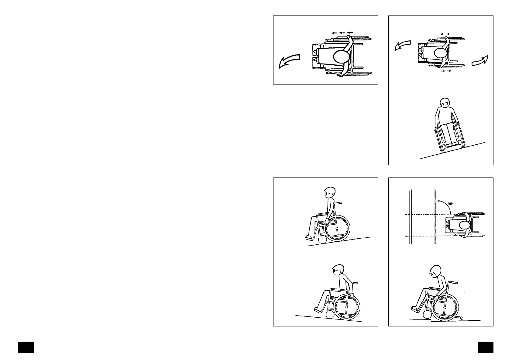
Negotiating a bend
Turning
▲ Tyres are made of a rubber com-
pound and may leave marks on some
surfaces (e.g. plastic, wooden or parquet flooring, rugs, carpets) that are
hard to remove or even permanent.
▲ To prevent damage from corrosion,
do not use the wheelchair in damp
conditions, do not travel through
puddles or water and do not expose
it to continuous rain.
Recommendations for travelling
at dusk or at night
▲ During periods of darkness, avoid
roads and cycle paths as far as possible. Wear light-coloured clothing that
can be seen at a distance.
2.4.1 User information
The following pages give general information and suggestions for handling
and use of the wheelchair in everyday
situations. Make yourself thoroughly and
carefully familiar with the wheelchair.
New driving situations must be practised
with the support of a helper.
▲ Before changing from one seating
option to another, or before leaving
or entering the wheelchair, always
lock the brakes to prevent the wheelchair from rolling away.
▲ T o lean the upper body well forward,
manoeuvre the wheelchair backwards until the swivel wheels face
forwards for increased stability.
Turning on a slope
Driving downhill Approaching an obstacle
Driving uphill
Obstacle crossing
1110
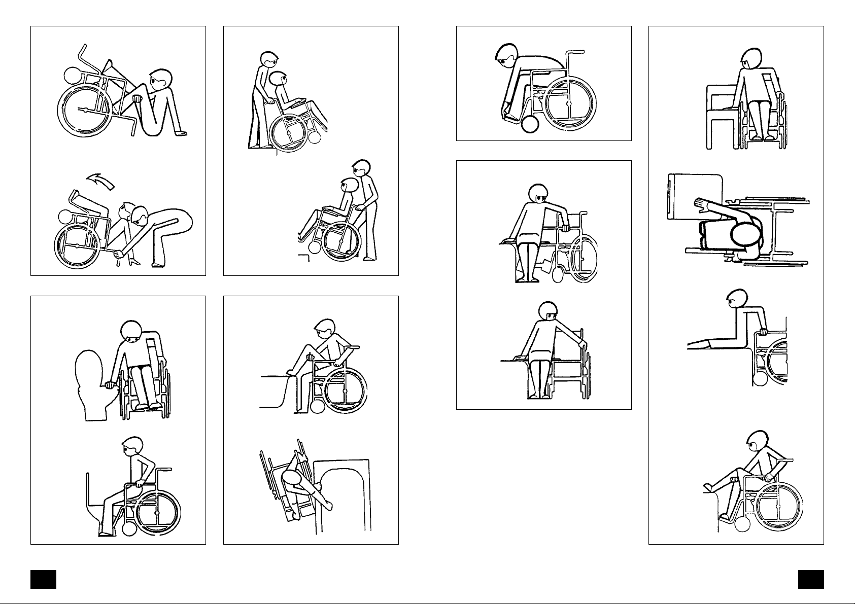
Climbing in
Crossing drops/steps
Steering wheels forwards = safe stability Transfer
Bringing the wheelchair upright
Toilet use Climbing into the bath
Transfer with sliding board
Lowering the legs
1312
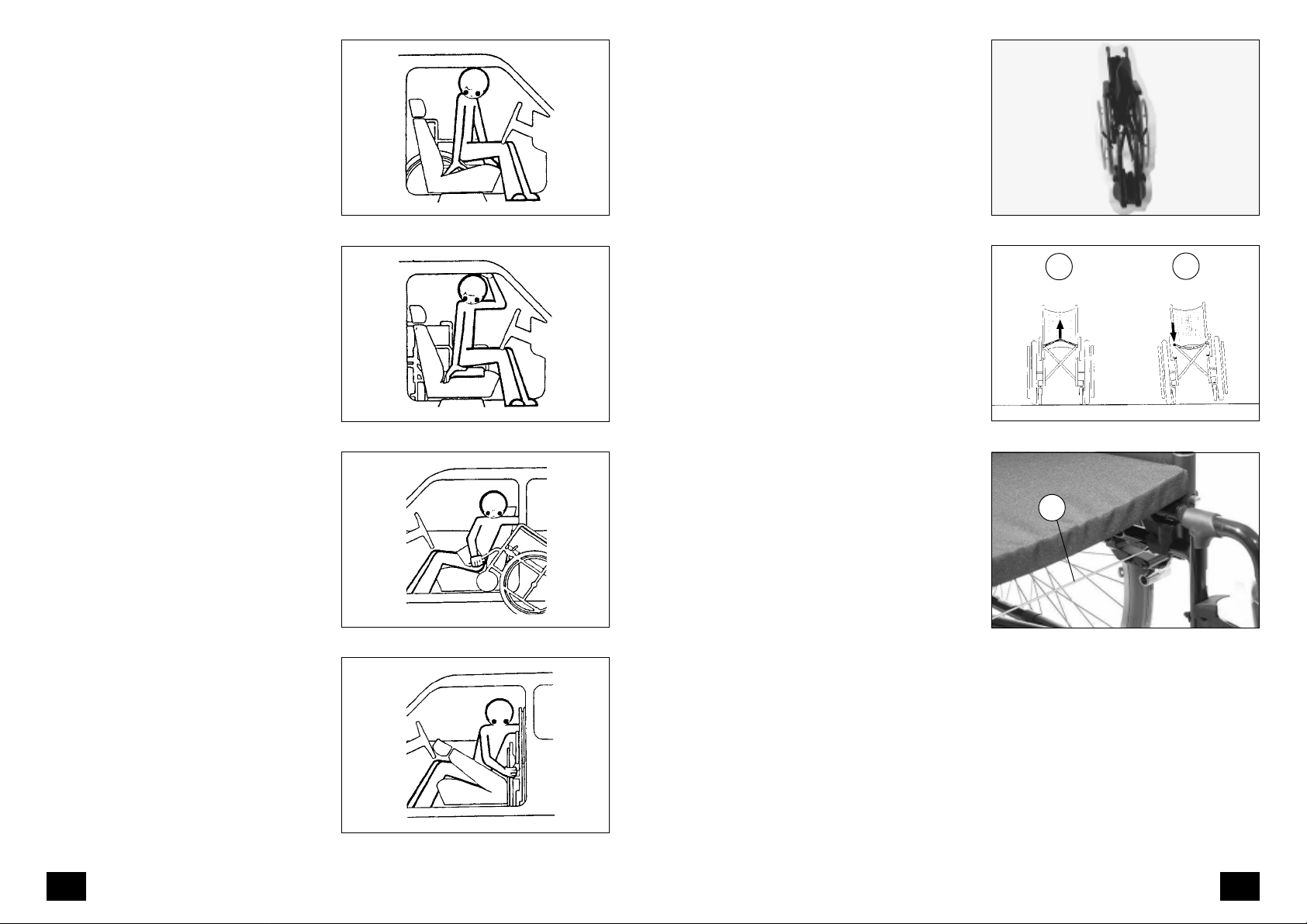
Wheelchair and the car
2.5 Folding/unfolding
Move the wheelchair parallel and adjacent to the driver or passenger seat.
Detach the legrests and the armrests in
order to reduce the wheelchair weight
and make the lifting into the car easier.
Lock the brakes to prevent the wheelchair from moving. The door frame can
be used for holding or the seat for support during the transfer into the car.
A sliding board can be used to bridge
the gap between the wheelchair and
the car seat. The possibilities here depend on the type of vehicle, the height
of the car seat and the height of the
wheelchair seat.
Unlock the brakes of the wheelchair
before its loading. The personal possibilities and the spaciousness of the vehicle determine whether the wheelchair
is now pulled into the car from the driver's seat or the front passenger seat.
Transferring to the car
Transfer into the car
2.5.1 Folding the wheelchair
To fold the wheelchair (Fig. 1), fold up
the foot plates of the leg supports or
remove the leg supports. Press the centre of the chest belt backwards. Lift the
back and the front of the seat cover upwards from the centre (Fig. 2/
➀).
2.5.2 Unfolding the wheelchair
To unfold the wheelchair, tilt it slightly
to one side. On the side which is standing firm on the ground, push the seat
tube downwards until it reaches its limit
(Fig. 2/
➁).
☞ Note:
To do this, it may be necessary to
force both seat tubes into their final
position by hand.
The Bowden wire (Fig. 2.1/
vents the side frames being pushed
too far apart.
➀) pre-
1
1
2
1
2
Two-door cars usually cause fewer problems because the doors are usually
wider. In the case of a four-door car it
may be necessary for a helper to lift the
wheelchair into the passenger space or
the boot.
Loading the wheelchair
Loading the wheelchair
2.1
1514

2.6 Transportation
For storage or transportation purposes,
the wheelchair can be dismantled into
portable elements without the need for
tools.
Firstly the dimensions of the wheelchair
can be reduced by removing all removable parts. These include the leg supports and the armrests (arm pads are
not removable). Stabilisers (if present)
can be folded forwards.
The wheelchair can now be folded in
the normal way. In addition, driving
wheels equipped with full floating axles
can now also be removed.
During reassembly, ensure that each
part is correctly installed and securely
fastened. Check that components are
correctly positioned. Check the correct
seating of the components.
3. Overview
The overview shows the most important
components and operating elements of
the IMPULS System wheelchair .
The components shown in the following illustrations may not be identical to
those on your wheelchair. The location
and handling of the parts are nevertheless applicable to your IMPULS System
wheelchair model. Each time the wheelchair is assembled, or each time a setting is made, checks should be carried
out to ensure that the component in
question is fitted correctly and functioning properly.
3.1 IMPULS 1
The model shown in Fig. 3 is representative of all IMPULS standard lightweight
wheelchairs.
– IMPULS 1
– IMPULS 1 Euro
– IMPULS 1 V ario
1 Sliding handle
2 Backrest
3 Armrest
4 Seat band
5 Leg support lock
6 Legrest
7 Footrest
8 Calf support
9 Swivel wheel
10 Brake and locking mechanism
11 Drive wheel
12 Hand wheel
1 3 Full floating axle
1
13
12
3
23
11
10 9
4
5
6
7
8
1716
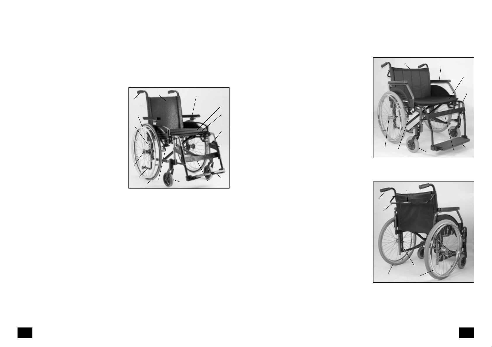
3.2 IMPULS 2-4
3.2a IMPULS XX
The model shown in Fig. 3 is representative of all IMPULS adaptable/activity
wheelchairs.
– IMPULS 2
– IMPULS 3 Hemi
– IMPULS 4
1 Sliding handle
2 Backrest
3 Armrest
4 Seat belt
4. 1 Seat cushion
5 Leg support lock
6 Legrest
7 Footrest
8 Calf support
9 Swivel wheel
10 Brake and locking mechanism
11 Drive wheel
12 Hand wheel
1 3 Full floating axle
1 4 Support wheel
15 Plate with punched holes for set-
ting variable seat height and wheel
position
1
15
13
14
3.1
12
2
10
The model shown in Fig. 3.2 and 3.3 is
representative of all IMPULS XX wheelchairs.
1 Sliding handle
2 Backrest
3 Armrest
3
4.1
4
5
6
7
911
8
4 Seat belt
5 Legrest
6 Leg support lock
7 Foot board
8 Calf support
9 Swivel wheel
10 Brake and locking mechanism
11 Drive wheel
12 Hand wheel
1 3 Full floating axle
14 Back stiffening bar
15 Plate with punched holes for set-
ting variable seat height and wheel
position
1 6 Sliding sleeve for dismantling back
stiffening bar
3.2
1
14
2
1013
16
3
4
5
6
7
9
8
3.3
11
15
12
1918

3.3 Components
3.3.2 Backrest
3.3.1 Seat band
The standard seat band can be adjusted
to two depths. After removing the end
caps (Fig. 4), the seat band and the seat
depth adapter can be pulled out from
the seat tube and replaced in any order, depending on the seat depth selected.
The ORTOFLEX seat cover can be adjusted on the underside using Velcro
strips.
3.3.1.1 Seat band XX
The seat band of the Impuls XX is fastened by four screws on each side, which
can be moved to two further positions,
each time by 3 cm, to adjust the seat
depth.
3.3 .1.2 Seat cushion
The seat cushion (accessory) is placed
with the rubberised side against the seat
band (Fig. 4.1).
4
4.1
The standard backrest has a rigid rear
tube with lumbar tilt (Fig. 6).
Warning:
Hanging bags or other objects behind the backrest increases the risk
!
of the wheelchair tipping over!
3.3.2.1 Backrest with angle adjustment
To adjust the angle from -12° to +12°
loosen the locking screw (Fig. 7/ ➀) on
each side and pull it out as far as required to engage the new setting.
Warning:
Adjust both sides equally .
!
After setting the angle (Fig. 8) re-tighten
the locking screws.
☞ Note:
If the seat back is angled too far forward, this can cause problems when
folding the wheelchair.
6
1
7
3.3 .1. 3 Fixed seat on the Impuls
XX
The Impuls XX with seat width 57 cm
and 60 cm is supplied with a fixed seat
(Fig. 5).
5
8
2120

3.3.2.2 Back band, standard
The standard back cover (Fig. 6) is
stretched into position by the rear tubes
when the wheelchair is unfolded.
The extended back section (Fig. 9/
➂)
is fastened below the seat area.
3.3 .2. 3 Back, ORTOFLEX
The tension of the back band can be
adjusted by means of Velcro strips (Fig.
9/
➁).
The ORTOFLEX pad
adjustable back band section using
➀ is fastened to the
➁
Velcro strips.
The extended back section (Fig. 9/
➂)
is fastened below the seat area.
ORTOFLEX
back band section
9
ORTOFLEX
pad
Standard
seat cover
Standard
back cover
3.3.2.4 Backrest with 30° angle
adjustment
For variable adjustment up to 30°, pull
the release levers (Fig. 9.1/
➀).
☞ Note:
Set both rear tubes to the same position when the seat is occupied.
Pistons should be kept clean and
lightly greased with Vaseline (Fig.
9.2) for lasting performance.
Warning:
Adjusting the angle increases the
danger of tipping over and should
!
only be undertaken if stabilisers are
fitted!
1
1
9.1
9.2
2322

3.3 .2. 5 Height-adjustable sliding
handles
The height of the sliding handles (Fig.
9.3) can be variably adjusted. The han-
dles can also be secured against twisting and pulling out of position
3.3.3 Armrest
Warning:
Do not use wheelchair without armrests/clothes guards fitted.
!
Do not lift wheelchair by armrests/
clothes guards.
1
2
2
For variable height adjustment, loosen
the locking screw (Fig. 9.4/
tighten when adjustment is complete.
3.3 . 2 . 6 Back stiffening bar
The Impuls XX for heavier users has a
back stiffening bar fitted as standard
(Fig. 9.5/
Before folding the wheelchair, the sliding sleeve for locking the back stiffening bar should be pushed outwards to
the right (Fig. 9.6/
➀).
➀).
➀). And re-
9.3
9.4
9.5
3.3.3.1 Clothes guard
The clothes guard (Fig. 10/
forwards or backwards over the centre
of the wheel.
The position of the clothes guard can
be adjusted by loosening the fixing
screws (Fig. 10/
1
1
Re-tighten the fixing screws when adjustment is complete.
Warning:
Do not push the clothes guards outwards when supporting yourself.
!
3.3.3.2 Non-locking armrest
The standard armrest (Fig. 11) can be
removed by pulling upwards. The armrest is installed by pushing the guide
tubes downwards as far as possible into
the corresponding openings.
➁).
➀) can swivel
10
11
9.6
1
2524

3.3 .3.3 Armrest with double
locking
To install the armrest, push the diagonally positioned rear pin (Fig. 12/
into the corresponding opening, then
swivel it forwards into the corresponding opening until you hear the locking
button click into place.
➀)
☞ Note:
When the armrest is swivelled forward, the rear lock (Fig. 12/
automatically engaged.
To remove the armrest, press the locking button (Fig. 13/
of the armrest free and pull upwards.
Warning:
When supporting yourself on plastic
armrests, place your hands over the
!
central column (Fig. 13).
3.3 .3. 4 Height-adjustable armrest
To adjust the height, push in the ratchet
button (Fig. 14/
rest pad in stages to the desired height.
To adjust the armrest height on the
Impuls XX, push the ratchet button (Fig.
14.1/
➀).
➁) swivel the front
➀) and bring the arm-
➀) is
12
13
14
3.3.4 Leg supports
Warning:
Do not use the leg supports to lift or
carry the wheelchair.
!
• For the Impuls XX model with sepa-
1
2
1
rate leg supports, the maximum permissible user weight is reduced to 130
kg!
3.3.4.1 Calf support
The calf support (Fig. 15/
on to the retaining pin on the leg support. The calf support can be adjusted
to the required length using the Velcro
fastening on the rear side of the support.
3.3.4.2 Folding up the foot
plates
Locking the brakes prevents the wheelchair from unintentional movement.
Remove the calf support and lift both
feet from the foot plates.
T o keep the foot area free, e.g. for "propelling" (moving the wheelchair forwards using the feet), the foot plates
should be folded to the side (Fig. 16).
➀) is pushed
15
16
17
1
14.1
1
2726

3.3. 4.3 Swivelling leg supports
aside
For transferring easily into or out of the
wheelchair or for moving close to a cupboard, bed, or bath, the leg supports
can be swivelled inwards or outwards
after the foot plates have been folded
up (Fig. 17).
Depending on the model and version:
a) Push the lever for locking the leg sup-
port (Fig. 18/
b)Lift the leg support from the locking
device (Fig. 19/
wards (Fig. 17).
For the Impuls XX model, the locking
pin must first be activated (Fig. 19.1).
Warning:
Leg supports which have been moved
aside are automatically unlocked and
!
can easily fall off. Note this when
handling (e.g. transport).
When putting the leg supports back
in position, remember to check the
levers (Fig. 18/
(Fig. 19/
➀) to the side or
➁) and swivel it out-
➀) or locking devices
➁).
18
19
19.1
3.3.4.4 Removal of leg supports
Before removing the leg supports, remove the calf support and fold up the
foot plates. Depending on the model
and version, the leg supports can now
be removed as follows:
1
2
a) Push the lever for locking the leg sup-
port (Fig. 20/
the leg supports slightly and remove
by pulling upwards.
b)Leg supports without locking levers
can be removed by pulling upwards.
3.3.4.5 Attachment of leg sup-
Depending on the model and version,
the leg supports are attached as follows:
a) Insert leg supports from above at an
angle into the leg support holders
(Fig. 21), and swivel supports forwards
until you hear them click into place.
b)Leg supports without a locking lever
are inserted from above into the leg
support holders. The locking device
(Fig. 22/
ess.
For the Impuls XX model, the locking pin
must first be activated (Fig. 19.1).
➀) to the side. Swivel
ports
➀) is activated in the proc-
20
21
22
1
1
2928

3.3 .4. 6 Positioning of foot plates
To set the foot plate position, the locking screws (Fig. 23/
➀)must first be re-
moved. Re-tighten screws.
When the screwed connections have
been loosened (Fig. 23/
➀) the position
of the foot plate can be adjusted by 1.5
cm either forwards or backwards. Retighten screwed connections.
3.3 .4. 7 Adjustment of foot plate
angle
After removing the locking screw (Fig.
24/
➁) pull out the teeth and set the
angle of the foot plate. Re-tighten screw.
The regulating screw (Fig. 24/3) is used
to correct the angle of the foot plate in
a crosswise direction.
23
24
3.3.4.8 Adjustment of foot plate
height
1
Depending on the model and version,
the height of the foot plate is adjusted
1
as follows:
a) After removing the locking screw (Fig.
➀) adjust the foot plate telescop-
24/
ically to the desired height. Observe
markings indicating maximum exten-
25
sion. Re-tighten locking screw.
b)After loosening the screwed connec-
tion (Fig. 25/
➀) adjust the foot plate
telescopically to the desired height.
Re-tighten screwed connection.
3.3.4.9 Foot board
The foot board can be folded up (Fig.
26).
When folding it down, ensure that the
lateral guide (Fig. 26.1/
on the locking pin (Fig. 26.1/
➀) is supported
➁).
26
1
If folding up to the other side is required,
the foot board can be pulled out after
2
loosening the screwed connections (Fig.
24/
➁), turned round and re-installed.
Re-tighten screwed connections.
Loosening the locking screws (Fig. 27/
➂) allows variable adjustment of depth
positioning. To adjust the angle, loosen
the locking screw (Fig. 27/
➁) and pull
out the teeth and set the angle of the
foot board. Re-tighten screw .
26.1
27
3
2
2
3130

3.3.4.10 Leg support with angle
adjustment (774-1)
When seated in the wheelchair, ask a
carer to raise the leg support to the desired level.
To lower the leg support, remove the
load momentarily from the support by
raising the lower thigh (ask a carer if
necessary), and push the clamping lever (Fig. 28/
The leg support can now be moved
slowly downwards.
Warning:
When setting the height-adjustable
leg support, never touch the adjust-
!
ment mechanism with your free
hand.
The position of the calf support can be
adjusted by installing it on the second
set of drilled holes (Fig. 29/
Loosening the locking screw (Fig. 29/
allows the calf pad to be moved upwards.
The length of the leg support can be
adjusted in stages after the screw (Fig.
29/
➃) has been loosened.
Re-tighten all screws when adjustment
is complete.
➀) forwards.
➁).
➂)
28
29
3.3.4.11 Leg support with angle
adjustment and length
compensation (774-2 AL)
When seated in the wheelchair, ask a
carer to raise the leg support to the desired level. The length of the leg sup-
1
3
2
4
port is automatically adjusted by spring
force.
To lower the leg support, remove the
load momentarily from the support by
raising the lower thigh (ask a carer if
necessary), and push the clamping lever (Fig. 29.1/
The leg support can now be moved
slowly downwards.
Warning:
When setting the height-adjustable
leg support, never touch the adjust-
!
ment mechanism with your free
hand.
The height and depth positioning of the
calf plate can be adjusted by installing
it in the corresponding holes (Fig. 29.1/
➀) forwards.
29.1
29.2
1
2
3
➁).
The length of the leg support can be
adjusted in stages after the screw (Fig.
29.1/
➂) has been loosened.
To adjust the angle of the foot plate,
loosen the locking screw (Fig. 29.2) located on the side, pull out the teeth and
set the new angle.
Re-tighten all screws when adjustment
is complete.
3332

3.3.5 Driving wheels
The driving wheels are mounted on a
fixed axle or a full floating axle, depending on the wheelchair model.
☞ Note:
The tyre pressure is shown on both
sides of the tyre surface and can also
be found in the Technical data.
3.3 .5 .1 Full floating axle
The driving wheels can be installed or
removed without the need for tools (Fig.
30). Free the axle by pressing on the
rubber cap and pull outwards.
To install the driving wheels, free the
axle by pressing on the rubber cap (Fig.
30) and push the wheel into the axle
opening until it locks.
Warning:
Each time the wheels are installed,
test the locking mechanism by pull-
!
ing/pushing the driving wheel from
the side (Fig. 31).
30
31
– The full floating axle must be kept
clean. A functional fault may occur
in the case of contamination due to
sand or earth or in the event of freezing of moist cold air.
– If the drive wheel has too much lat-
eral play or the full floating axle does
not lock, it should be repaired immediately by an authorised ORTOPEDIA dealer.
3.3.5.2 Hand wheels
The distance between the hand wheels
and the driving wheels is adjustable. To
change this distance, loosen the four fixing screws (Fig. 32/
one turn. Move the hand wheel to the
required position parallel to the driving
wheel. Tighten the fixing screws crosswise.
3.3.6 Brakes
The wheelchair can be halted via the
hand wheels, the toggle joint brakes
(Fig. 33) or the drum brakes (carers
only).
3.3.6.1 Safety information
▲ The wheelchair must not be pushed
when the brakes are locked on.
▲ If the braking effect reduces, the
wheelchair should be repaired immediately at an authorised repair centre.
▲ In order to prevent unwanted swerving when stopping the wheelchair or
when locking the brakes on a sloping
surface, both brake levers should be activated simultaneously .
➀) by approximately
1
32
33
3534

▲ Do not lean on the lateral brake lever
(Fig. 34/
!
3.3 .6.2 T oggle joint brake
➀).
Warning:
The braking effect is dependent on:
– the condition of the tyres,
– the condition and fixing of the
brakes,
– the brake lever setting,
– the quality of the road surface.
34
3.3.6.5 Locking the brake
1
To secure the wheelchair against unintentional movement, both lateral brake
levers should be pushed forward until
they reach their limit stops (Fig. 36).
3.3.6.6 Releasing the brake
To release the brake, both brake levers
should be pulled backwards until they
reach their limit stops (Fig. 37).
36
Activation of the toggle joint brake causes
a brake bolt to press on the tyre (Fig.
35).
3.3 .6.3 Drum brake
Activation of the drum brake causes
brake pads to press against the wheel
hub from the inside.
3.3. 6.4 Service brake function
For measured braking, the lateral brake
levers of the toggle joint brakes (Fig. 34/
➀) should be pushed forward slightly
and equally.
35
3.3.6.7 Changing or replacing
driving wheels
After a change of driving wheels, checks
should be made to ensure that the
brakes are functioning correctly. The
brakes should then be reset if necessary
Driving wheels with PU tyres require a
special toggle joint brake.
When changing to a wheel with PU tyres,
or from PU tyres to another type of tyre,
the toggle joint brakes must be changed
at the same time.
37
3736

3.3 .6. 8 Drum brake for carers
3.3.7 Swivel wheels
(Fig. 37.1)
T o lock the brake lever once it has been
applied (
the rocker lever upwards (
the brake, pull up the brake lever (
➀), press the forward part of
➂). T o release
➀)
and press on the rear part of the rocker
➁).
arm (
3.3 .6. 9 Adjustment of toggle
joint brake
☞ Note:
After modifications/adjustments to
the chassis, the brakes must be reset.
Please observe the safety information given in Section 3.3.6.1!
Before resetting the brakes, the tyre
pressure must be checked and, if
necessary , adjusted. The correct tyre
pressure is given in the Technical
data.
Loosen the screws of the clamping device (Fig. 38/
brake. Dimension X = 21 mm. When
adjustment is complete, re-tighten the
clamping device screws. Check that the
braking effect of the toggle joint brakes
is equal and that the brakes are functioning correctly .
➀). Move the toggle joint
37.1
38
The swivel wheels can be easily replaced
(Fig. 39).
T o remove the wheels, unscrew and remove the axles.
The correct tyre pressure can be found
1
2
3
in the Technical data or on the outer
surface of the tyre.
39
3.3.8 T yres
Pneumatic tyres:
The appropriate tyre pressures are given
in the >T echnical data <. The maximum
1
pressure is shown on the outer surface
of the tyre.
Solid tyres:
><
X
These can be distinguished by the absence of a compressed air valve.
3938

4. Individual
customisation
This setting option offers:
– customised adjustment of the seat
height to suit your lower thigh length,
– customised adjustment of seat incli-
nation for user,
– increased stability against tipping up.
Warning:
– Customised adjustment or modifi-
cation should only be carried out
!
by an authorised dealer.
– Any new adjustment may have an
effect on performance.
4.1 Seat height/seat
inclination
Customised setting of seat height and
inclination involves:
– changing the driving wheel size,
– moving the adapter (Fig. 43.1/
or axle holder (Fig. 40+41/
adaptable/activity model range) vertically within the perforated plate
(
➁).
– Changing the swivel wheel size.
– setting the angle on the castor con-
trol socket (Fig. 42/
➂).
➁)
➀, in the
40
41
42
4.1.1 Driving wheel position
The driving wheel position depends on:
– the desired seat height,
2
2
3
1
1
– the wheel size,
– the seat inclination,
– the swivel wheel.
Warning:
If the perforated plate (Fig. 43/
positioned horizontally, the wheel
!
position changes, which also results
in a change in performance.
– Each forward movement of the per-
forated plate increases the risk of tipping up!
– Positioning a wheel adapter (Fig.
43.1/
➁) on the inside increases the
risk of tipping up!
➁) is
2
43
2
43.1
4140

4.1.2 Swivel wheel position
The required swivel wheel position (Fig.
44) is determined according to the po-
sition specified for the driving wheel.
☞ Note:
Each time the position of the driving
wheel is changed, the castor control
socket (Fig. 45/
➂) must be reset.
4.2 Wheel camber
Changing the wheel camber is only
possible with the perforated plate of the
IMPULS 3
Various wheel cambers (Fig. 46) can be
set by inserting camber discs of 0°– 4°.
.
44
5. Optional accessories
Optional accessories are not included in
the standard scope of supply .
5.1 Lap belt
The lap belt is used for securing a person sitting in the wheelchair .
– Additional stabilisation of the sitting
position.
– Prevents the wheelchair user from
tipping out of the wheelchair (depends on degree of disability).
– Continuous adjustment to suit the
3
user’s needs.
5.1.1 Fastening lap belt
Pull both belt bands forwards and push
the two parts of the fastening together.
Then carry out a pull test.
Warning:
Please ensure that nothing is stuck
under the belt in order to avoid pain-
!
ful bruising! – Thus you avoid painful
pressure points
Warning:
Customised adaptation or modification should only be carried out by an
!
authorised dealer.
45
46
☞ Note:
A lap belt should only be retrofitted
by an authorised dealer!
Warning:
The lap belt is not part of the retaining system for the wheelchair and/
!
or occupant during transportation in
a vehicle for transporting disabled
persons.
5.1.2 Setting belt length
☞ Note:
The lap belt should be pulled tightly
but should not pinch.
4342

5.2 Stabilisers
5.2.2 Setting the height
The stabilisers (Fig. 48) provide increased
stability from tipping and can be swivelled inwards under the seat (Fig. 49).
Warning:
In certain situations, stabilisers do not
provide sufficient protection against
!
overturning.
Therefore never:
▲ Lean the upper body too far back.
▲ Start off too quickly , particularly when
travelling uphill.
☞ Note:
Please observe the advice given in
the booklet "Safety Information for
Mechanical Wheelchairs"!
5.2.1 Swivelling the stabilisers
Push the stabilisers downwards from the
locking device, then swivel them inwards under the seat (Fig. 49) until the
locking element engages automatically
at the top.
48
49
The stabiliser tube is height-adjustable.
Loosen the locking screws (Fig. 50/
position the stabiliser tube (Fig. 50/
according to the driving wheel. Retighten locking screws.
Warning:
T o provide sufficient stability from tipping, both stabilisers must be set to
!
the same height.
5.2.3 Correct stabiliser length:
In order to ensure sufficient support, the
stabilisers must extend beyond the driving wheel.
➀),
➁)
5.3 Tread cap
The tread cap (Fig. 51/ ➀) is used by
the carer to tilt the wheelchair when
negotiating obstacles and can be
mounted on the right or left.
5.3.1 Setting the height
To set the height, loosen the locking
screws (Fig. 51/
screws when adjustment is complete.
➁). Re-tighten locking
1
2
50
1
2
51
4544

5.4 Transit wheels
5.5 Spoke guard
For narrow openings or passages (e.g.
in trains) the transit wheels (Fig. 53/
allow the wheelchair to be pushed by a
carer without using the driving wheels.
5.4.1 Setting the height
Loosen the locking screws (Fig. 52/
and position the tube as required. Retighten locking screws.
5.4.2 Removing driving wheels
Before removing the driving wheels,
push in the spring-loaded button (Fig.
52/
➀). Push the transit wheel down-
wards to the floor. Tilt the wheelchair
on one driving wheel and push the transit wheel downwards until the button
engages (Fig. 53/
ing wheel.
5.4.3 Locking brake
Lock and release the transit wheel by
operating the kick bar (Fig. 53/
➀). Remove the driv-
➀)
➁)
➂).
52
53
1
2
1
3
The spoke guard prevents injury to
hands from touching the turning spokes.
It also protects the spokes against damage.
5.5.1 Removal
To remove the spoke guard, unscrew the
screwed connection (Fig. 54) and carefully push the guard through the hand
wheel.
5.5.2 Installation
To fit the spoke guard, position the indentations on the circumference of the
guard over the hand wheel support bars.
5.6 Brake lever exten-
54
1
55
sion
Remove the handle (Fig. 55/ ➀), to enable insertion of the brake lever extension (Fig. 56/
➁).
2
56
4746

5.7 Tray
Warning:
Always ensure that brakes are secured
before the installation, setting, adjust-
!
ment or removal of the tray.
• Sharp objects (e.g. watches, rings,
knives or belt buckles) or coarse
grains of dirt can leave unsightly
scratches and grooves on the tray
surface.
• Do not use aggressive or abrasive
substances to clean the tray!
• Do not place hot objects on the tray!
• Do not travel with the tray in place if
it holds loose objects or containers
filled with liquid!
5.7.1 Standard tray
The tray is pushed over the armrest pads
from the front (Fig. 57).
Warning:
For guaranteed stability of the tray,
only armrests with long armrest pads
!
should be used (Fig. 57).
5.7.2 8001 tray
On the XX model, the guide bar of the
8001 tray is pushed into the holder on
the armrest (Fig. 57.1) and secured using the locking screw (Fig. 57.1/
Loosening the locking screw (Fig. 57.1/
➀) allows the tray to be swung to the
side (Fig. 57.2).
➀).
57
57.1
57.2
6. Care and maintenance
6.1 Care
Seat and back cover:
Clean the covers with warm water .
In the case of stubborn soiling, the
fabric can be washed with a standard washing powder for delicate
fabrics. Spots can be removed with
a sponge or a soft brush. Do not
soak! Do not use a washing machine!
Do not use aggressive cleaning
agents e.g. solvents, or hard brushes etc.
1
Rinse with clear water and let get
dry.
Rinse with clean water and leave to
dry naturally. To disinfect, use commercial brands and observe the instructions for use given on the product.
Plastic parts:
The side panel on the side section
and some other elements are of
high quality plastic. Take care of
these by means of standard plastics cleaning agents. Always observe
the specific product information.
Finish:
The high quality surface finish guarantees
optimal protection against corrosion. If the
surface finish is damaged by scratches or
similar, touch it up with a varnish pen available from us. Occasional application of a light
cover of oil to all moving parts (see also Maintenance Instructions) will ensure that your
wheelchair will give you many years of service.
Tyres:
Check tyre pressure regularly. Ensure pres-
sure on both tyres is correct and equal.
Tyre pressure: See Technical data.
Check condition of tyres regularly (wear,
deterioration).
4948

Chassis:
The chassis and wheels can be cleaned
with a damp cloth using a mild detergent. Dry thoroughly after cleaning.
Check the chassis for corrosion and other
damage. Clean the plastic parts using a
mild commercial detergent suitable for
plastics.
Brakes:
Check that brakes are working properly
and are easy to use.
Removable parts
Check that removable parts, e.g. leg
supports, armrests and driving wheels
are firmly and securely fixed in position.
Moving parts:
Check all moving parts are functional
and unobstructed.
6.2 Maintenance
To ensure safety and to prevent accidents as a result of wear on components
going undetected, the wheelchair
should be checked and serviced annually by an ORTOPEDIA dealer. The
ORTOPEDIA dealer will check and maintain all safety-relevant parts of the wheelchair and check the operability and the
operational safety. He will be able to
recognise the onset of wear and will use
only original ORTOPEDIA spare parts or
parts tested and approved by
ORTOPEDIA.
6.2.1 T ools
The following tools are required for setting and adjustment carried out by the
user:
Hexagon socket head wrench DIN 911
1x WA* 4 mm
1x WA* 5 mm
1x WA* 6 mm
Open (face) or box spanner
1x WA* 8 mm
1x WA* 10 mm
* WA = width across
6.2.2 Maintenance instructions
Before setting out:
▲ Check brake unit for correct function.
Operate brake lever until it reaches its
limit. The locked wheels should not be
able to turn under operating conditions.
If they can still turn, the brakes must be
repaired by an authorized specialist
workshop.
▲ Check toggle joint brake for wear
Move brake lever sideways. There should
not be excessive play .
▲ Check tyre pressure
Standard values
Standard tyre: 2.5 bar
Easy tyre: 7,5 bar
☞ Note:
Always observe the pressure stated
on the tyre.
▲ Check tyre profile
If the tyre profile is worn down or if the
tyre is damaged, consult an authorized
specialist workshop for repairs.
▲ Check rear tubes for stability
In the event of deformation or cracking
around the soldered seams, contact an
authorised repair centre immediately for
repair. – Danger of accidents!
Every 8 weeks
(depending on frequency of use)
▲ Lubricate the following components
with a few drops of oil:
– cross brace bearings.
– Moving parts of the locking mecha-
nism.
– Brake lever bearings.
Components must be free from used oil
residues before lubrication.
Please ensure that excess oil does not
contaminate the environment (e.g. your
clothing)
▲ Check that all screwed connections
are tight.
▲ Check that the sliding handles are
tight by forceful twisting.
Every 6 months
(depending on frequency of use)
▲ Check:
– Cleanliness, see Care section.
– General condition, see Care and maintenance section.
5150

6.2.3 Punctures
6.3 Repairs
6.5 Spare parts
If pneumatic tyres are punctured by
sharp objects such as nails, screws, glass
slivers etc., the puncture should be repaired (by mending the inner tube) or
the tube replaced.
Warning:
Before repairing a tyre, the air valve
must be opened in order to let out
!
the air remaining in the tube.
The outer part of the tyre must be
removed and replaced using appropriate tyre levers (bicycle accessories).
Do not use a screwdriver or other
pointed or sharp-sided object as a
lever!
Swivel wheels:
Before replacement or repair, the swivel
wheel axle must be removed (Fig. 58).
☞ Note:
Observe the position of any sleeves
or washers for reassembly.
Consult your repair centre for repairs
and servicing. Centres are experienced
in this work and usually employ specially
trained personnel.
6.4 Customer service
Should you have any questions or require
assistance, please consult your
ORTOPEDIA dealer, who has been
trained at our factory in accordance with
our guidelines and can give advice as
well as carry out servicing and repairs.
Parts can only be obtained through your
dealer. In the event of repairs, use only
original ORTOPEDIA spare parts.
To enable the correct supply of spare
parts, always quote the appropriate serial number, which is shown on the
nameplate!
For all modifications carried out on the
wheelchair, the dealer must add the
date of modification and the appropriate assembly instructions to the wheelchair Operating Instructions.
This ensures that no incorrect details will
be given for future orders of spare parts.
58
5352

7. T echnical data
7.1 Impuls 1 model
Dimensions
Length across leg supports........................104 cm
Height....................................................... 90 cm
Width of seat: 40 / 43 / 46 / 48 cm ...........Seat depth: 40 / 42 / 44 cm
Seat width, folded.....................................31 cm
Seat height ...............................................48 / 50,5 cm
Back height ...............................................40 cm
Armrest height..........................................23 cm
Seat height and seat angle with 24" driving wheels
Swivel wheel: ............................................ 200 x 50 (8“)
Seat height: 50,5 cm.................................Seat angle: 2,5°
Seat height and seat angle with 22" driving wheels
Swivel wheel: ............................................6“
Seat height: 48 cm....................................Seat angle: 2,5°
Tyres/T yre pressures........................... Standard values
Swivel wheel 6“ ........................................solid
Swivel wheel 200 x 50 mm........................ 2,5 bar
Driving wheel 22“ x 1“ .............................7,5 bar
Driving wheel 22“ x 1
Driving wheel 24“ x 1“ .............................7,5 bar
Driving wheel 24“ x 1
☞ Note:
Always observe the pressure stated on the tyre.
3
/8“ ......................... 4,5 bar
3
/8“ ......................... 4,5 bar
7.2 Impuls 1 Euro model
Dimensions
Length across leg supports........................113 cm
Height....................................................... 90 – 95 cm
Width of seat: 40 / 43 / 46 cm................... Seat depth: 40 / 42 / 44 cm
Seat width, folded.....................................31 cm
Seat height ...............................................45,5 – 50 cm
Back height ...............................................40 cm
Armrest height..........................................23 cm
Seat height and seat angle with 24" driving wheels
See order form
Tyres/T yre pressures........................... Standard values
Swivel wheel 6“ ........................................solid
Swivel wheel 200 x 50 ............................... 2,5 bar
Driving wheel 24“ x 1“ .............................7,5 bar
Driving wheel 24“ x 1
☞ Note:
Always observe the pressure stated on the tyre.
Distance from hand wheel ........................ two positions can be set
Weights
Weight when empty..................................from 12,6* kg
Max. passenger weight
Seat width up to 46 cm .............................130 kg
3
/8“ ......................... 4,5 bar
(depending on model and version)
Distance from hand wheel ........................ two positions can be set
Weights
Weight when empty..................................from 12,6* kg
(depending on model and version)
Max. passenger weight
Seat width up to 46 cm .............................130 kg
Seat width 48 cm ......................................130 kg (with double cross brace)
* = Seat width 43 cm, without armrests and leg supports
* = Seat width 43 cm, without armrests and leg supports
5554

7.3 Impuls 1 Vario model
7.4 Impuls 2 model
Dimensions
Length across leg supports........................110 cm
Height....................................................... 90 – 101 cm
Width of seat: 38 / 40 / 43 / 46 / 48 cm ....Seat depth: 40 / 42 / 44 cm
Seat width, folded.....................................31 cm
Seat height ...............................................41,5 – 52 cm
Back height ...............................................40 cm
Armrest height..........................................23 cm
Seat height and seat angle with 22" or 24" driving wheels
See order form
Tyres/T yre pressures........................... Standard values
Swivel wheel 4“x 1¼.................................solid
Swivel wheel 5“x 1¼.................................solid
Swivel wheel 7“x 1¼.................................solid
Swivel wheel 7“x 1¾................................. 2,5 bar
Driving wheel 22“ x 1“ .............................7,5 bar
Driving wheel 22“ x 1
3
/8“ ......................... 4,5 bar
Driving wheel 24“ x 1“ .............................solid rubber
Driving wheel 24“ x 1“ .............................7,5 bar
Driving wheel 24“ x 1
3
/8“ ......................... 4,5 bar
☞ Note:
Always observe the pressure stated on the tyre.
Distance from hand wheel ........................ two positions can be set
Weights
Weight when empty..................................from 13,0* kg
(depending on model and version)
Max. passenger weight
Seat width up to 46 cm .............................130 kg
Seat width 48 cm ......................................130 kg (with double cross brace)
* = Seat width 43 cm, without armrests and leg supports
Dimensions
Length across leg supports........................102 cm
Height....................................................... 91 – 105 cm
Width of seat: 38 / 40 / 43 / 46 / 48 cm ....Seat depth: 40 / 42 / 44 cm
Seat depth (2nd frame): ........................... Seat depth: 44 / 46 / 48 cm
Seat width, folded.....................................31 cm
Seat height ...............................................40 – 51 cm
Back height ...............................................30 – 50 cm
Armrest height..........................................19 – 28,5 cm
Seat height and seat angle with 22" or 24" driving wheels
See order form
Tyres/T yre pressures........................... Standard values
Swivel wheel 4“, 5“, 6“, 7“.......................solid
Swivel wheel 7“x 1¾................................. 2,5 bar
Swivel wheel 200 x 50 mm........................ 2,5 bar
Driving wheel 22“ x 1“ .............................7,5 bar
Driving wheel 22“ x 1
3
/8“ ......................... 4,5 bar
Driving wheel 24“ x 1“ .............................7,5 bar
Driving wheel 24“ x 1
3
/8“ ......................... 4,5 bar
☞ Note:
Always observe the pressure stated on the tyre.
Distance from hand wheel ........................ two positions can be set
Weights
Weight when empty..................................from 13,9* kg
(depending on model and version)
Max. passenger weight
Seat width up to 46 cm .............................130 kg
Seat width 48 cm ......................................130 kg (with double cross brace)
* = Seat width 43 cm, without armrests and leg supports
5756

7.5 Impuls 3 model
7.6 Impuls 4 model
Dimensions
Length across leg supports........................93,5 – 96 cm
Height....................................................... 82 – 94 cm
Width of seat: 38 / 40 / 43 / 46 / 48 cm ....Seat depth: 40 / 42 / 44 cm
Seat width, folded.....................................31 cm
Seat height ...............................................36 – 42 cm
Back height ...............................................30 – 50 cm
Armrest height..........................................19–28,5 cm
Seat height and seat angle with 22" or 24" driving wheels
See order form
Tyres/T yre pressures........................... Standard values
Swivel wheel 4“, 5“, 6“.............................solid
Driving wheel 22“ x 1“ .............................7,5 bar
Driving wheel 22“ x 1
3
/8“ ......................... 4,5 bar
Driving wheel 24“ x 1“ .............................7,5 bar
☞ Note:
Always observe the pressure stated on the tyre.
Distance from hand wheel ........................ two positions can be set
Weights
Weight when empty..................................from 12,3* kg
(depending on model and version)
Max. passenger weight
Seat width up to 46 cm .............................130 kg
Seat width 48 cm ......................................130 kg (with double cross brace)
* = Seat width 43 cm, without armrests and leg supports
Dimensions
Length across leg supports........................98 cm
Height....................................................... 91 – 105 cm
Width of seat: 38 / 40 / 43 / 46 / 48 cm ....Seat depth: 40 / 42 / 44 cm
Seat depth (2nd frame): ........................... Seat depth: 44 / 46 / 48 cm
Seat width, folded.....................................31 cm
Seat height ...............................................44 – 51 cm
Back height ...............................................30 – 50 cm
Armrest height..........................................19 – 28,5 cm
Seat height and seat angle with 22" or 24" driving wheels
See order form
Tyres/T yre pressures........................... Standard values
Swivel wheel 4“, 5“, 6“, 7“.......................solid
Swivel wheel 7“x 1¾................................. 2,5 bar
Driving wheel 22“ x 1“ .............................7,5 bar
Driving wheel 22“ x 1
3
/8“ ......................... 4,5 bar
Driving wheel 24“ x 1“ .............................7,5 bar
Driving wheel 24“ x 1
3
/8“ ......................... 4,5 bar
☞ Note:
Always observe the pressure stated on the tyre.
Distance from hand wheel ........................ two positions can be set
Weights
Weight when empty..................................from 12,6* kg
(depending on model and version)
Max. passenger weight
Seat width up to 46 cm .............................130 kg (with double cross brace)
Seat width 48 cm ......................................130 kg (with double cross brace)
* = Seat width 43 cm, without armrests and leg supports
5958

7.7 Impuls XX model
Dimensions
Length across leg supports........................100 cm
Height....................................................... 95 cm
Width of seat: 48 / 51 / 54 / 57 / 60 cm ....Seat depth: 42 / 45 / 48 cm
Seat width, folded.....................................29 cm
Seat height ...............................................44 – 51,5 cm
Back height ...............................................40, 45 cm
Armrest height..........................................19 – 28,5 cm
Seat height and seat angle with 22" or 24" driving wheels
See order form
Tyres/T yre pressures........................... Standard values
Swivel wheel ø 142 mm ............................solid
Swivel wheel ø 200 x 50 mm ....................solid
Swivel wheel ø 200 x 50 mm ....................2,5 bar
Swivel wheel 7“x 1¼.................................solid
Swivel wheel 7“x 1¾................................. 2,5 bar
Driving wheel 22“ x 1
Driving wheel 22“ x 1
Driving wheel 24“ x 1
Driving wheel 24“ x 1
3
/8“ ......................... solid
3
/8“ ......................... 4,5 bar
3
/8“ ......................... solid
3
/8“ ......................... 4,5 bar
9. Guarantee
The guarantee period for each of these products is 24 months and covers material
and manufacturing defects. Excluded are wearing parts and parts/assemblies that
are subject to normal wear and damage resulting from over-stressing, improper
handling, damage through use of force or improper/unauthorised modification/
repair.
Please contact your dealer where you purchased the product in the event of a
guarantee claim.
For product liability reasons, repair and maintenance work may only be carried out
by an authorised dealer and only original–ORTOPEDIA–spare parts may be used for
such repair/maintenance.
The products are subject to technical improvement and design modification.
This publication is valid as of December 2000.
ORTOPEDIA GmbH, Kiel
This product complies with EU – Directive 93/42/EEC for
medical products.
☞ Note:
Always observe the pressure stated on the tyre.
Distance from hand wheel ........................ two positions can be set
Weights
Weight when empty..................................from 17,8* kg
(depending on model and version)
Max. user weight: ................................................................................160 kg
Max. permissible user weight when using separate leg supports: ........ 130 kg
* = Seat width 48 cm, without armrests and leg supports
6160

Notes:
Please send me your current catalogue and product information, free of
charge and without obligation, on the following:
WheelchairsWheelchairs
Wheelchairs
WheelchairsWheelchairs
Universal and activity wheelchairs, wheelchairs for toilet and shower,
electric wheelchairs, scooters,
accessories
Aids for domestic care, everAids for domestic care, ever
Aids for domestic care, ever
Aids for domestic care, everAids for domestic care, ever
Bath and toilet equipment, mobility aids and equipment, home care
yday life and rehabilitationyday life and rehabilitation
yday life and rehabilitation
yday life and rehabilitationyday life and rehabilitation
6362

Sender:
Name
Street
Please prepay
if stamp
available
Postcode Town
Tel.
Fax.
Active and universal wheelchairs
Toilet and shower wheelc hairs
Electric wheelchairs
Scooter
Equipment for home care, everyday life and the rehabilitation
Response
ORTOPEDIA GmbH
– Öffentlichkeitsarbeit –
Postf ach 64 09
D-24125 Kiel
ORTOPEDIA GmbH
Postfach 64 09
Salzredder 30
T elephone +49 (0)431 2003 -0
Fax +49 (0)431 2003 - 378
Ident – Nr. 8 460 199 – 5101
•
http://www.ortopedia.de
0301 – 1 – 1. ST
• D-24125 Kiel
• D-24149 Kiel
QM system
certification according
to DIN EN ISO 9001
and DIN EN 46001
64
Technical consultancy
We reserve the right to make technical modifications to our products
and accept no responsibility for printers' errors and colour variations
in our publications!
• Sales • Service
 Loading...