

Page 1

AS-212R / AS-309R
Userguide
Page 2

Contents
Introduction .......................................................................................... 4
Parts identification – AS-212R ................................................................ 5
Dimensions – AS-212R ......................................................................... 6
Specifications – AS-212R ...................................................................... 7
Parts identification – AS-309R ............................................................... 8
Dimensions – AS-309R ......................................................................... 9
Specifications – AS-309R ..................................................................... 10
Packing list – AS-212R and AS-309R ..................................................... 11
Guidelines for tonearm care maintenance and warranty protection ........... 12
How to setup your tonearm ................................................................... 14
3
Page 3

Introduction
Headshell
(Not included)
Universal
connector
Arm tube
Cartridge
(Not included)
Arm lift
Tonearm base
Anti-skating
Tracking force scale
Counterweight
Arm rest
The Reference Tonearm series is a prime example
of how the Danish design philosophy and Japanese
precision can produce a truly exceptional product.
Since 1953, Ortofon has been designing tonearms with the goal of
combining craftsmanship and technology, and the Reference Tonearm
series is the culmination of decades of experience and expertise in the
field of audio engineering. It improves upon the great build of our original
legacy AS-212 and AS-309 models, combining exquisite design, precision
manufacturing, and attention to detail, resulting in a beautifully designed
tonearm that delivers outstanding performance.
The classic and beautiful S-shaped tonearm tube is crafted from highgrade aluminum alloy, offering an optimal combination of rigidity and mass.
The Reference tonearms are intuitive and easy, featuring improved highgrade bearings, a universal brass connector, and a high-strength alloy that
enhances rigidity. The internal wiring uses Flexible Copper Wire to allow
the arm to move freely without affecting its movement. Its beautiful design
and compatibility with a wide range of cartridges and turntables make it an
attractive option for any vinyl lover.
4
About the included counterweights
The tonearm comes with two types of counter weights: a standard weight
and a heavy weight, which can be utilized according to the car tridge’s
weight to allow mounting a wide range of cartridges.
For the AS-212R/309R, the standard weight is used for car tridges on
headshell with a total weight of 18 to 26 g, and the heavy weight is for
cartridges on headshell weighing 26 to 38 g.
Page 4
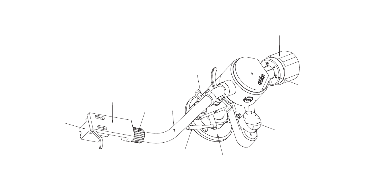
Parts identification – AS-212R
Headshell
(Not included)
Cartridge
(Not included)
Universal
connector
Arm tube
Counterweight
Arm rest
Tracking force scale
Anti-skating
Arm lift
Tonearm base
Figure 1
5
Page 5
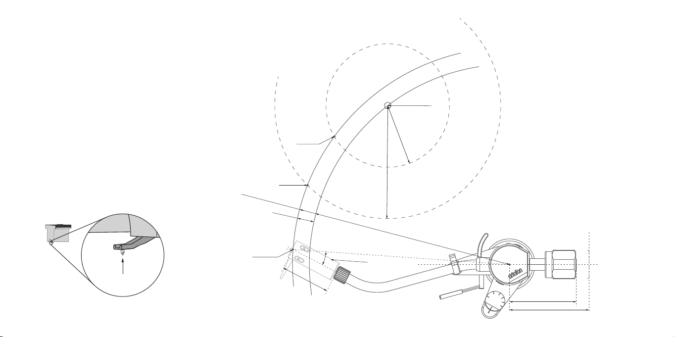
Dimensions – AS-212R
1:4
Stylus point
E
f
fec
t
i
v
e
len
gt
Stylus point
h
O
:
232 m
v
Null point
m
er
h
ang
Null point
1
8
52
m
m
Center spindle
R
66
R
1
20
.
9
Mounting distance: 214 mm
2
3
.
O
7
f
f
se
t
an
g
l
5
°
e
70.5 mm
Maximum elongation: 85 mm
Figure 2
6
Page 6

Specifications – AS-212R
Arm base
• Arm base fixing screw position: 40 mm in diameter from the center
of the base.
• Three screws are equally spaced at 120°.
Ø3.2
Ø18
Ø40
Ø54.6
Figure 3
Ton ea rm
• Mounting distance: 214 mm
• Effective length: 232 mm
• Overhang: 18 mm
• Offset angle: 23.75°
• Stylus point to the rear end of headshell: 52 mm
• Tonearm geometry: Baerwald alignment (IEC recommendation, the null
point is 66.04 and 120.9 mm)
• Arm shaft diameter: 18 mm
• Recommended arm shaft hole diameter:: 22 mm
• Cartridge weight: 18 to 26 g (with standard weight, including headshell)
• Cartridge weight: 26 to 38 g (with heavy weight, including headshell)
• Tonearm weight: 600 g / 630 g standard weight/heavy weight
• Height above mounting sur face: 59 – 79 mm (up to top of the tonearm)
• Counterweight radial clearance: 80 mm for standard weight; 89 mm for
heavy weight (measured from pivot point)
• Distance from mounting surface to top of platter: 20 – 48 mm
• Effective arm mass: 7 g
7
Page 7
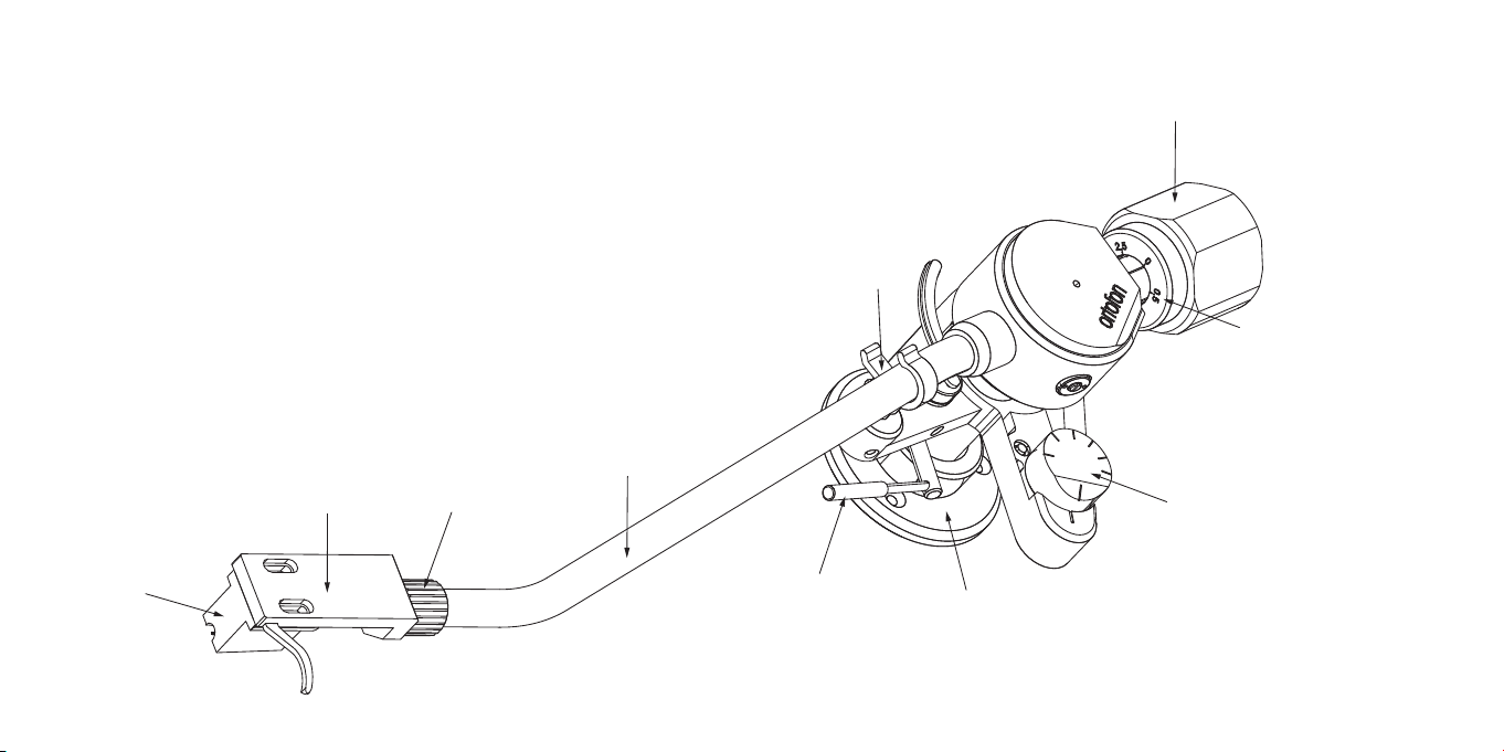
Parts identification – AS-309R
Counterweight
Arm rest
Tracking force scale
8
Cartridge
(Not included)
Headshell
(Not included)
Universal
connector
Arm tube
Arm lift
Anti-skating
Tonearm base
Figure 4
Page 8
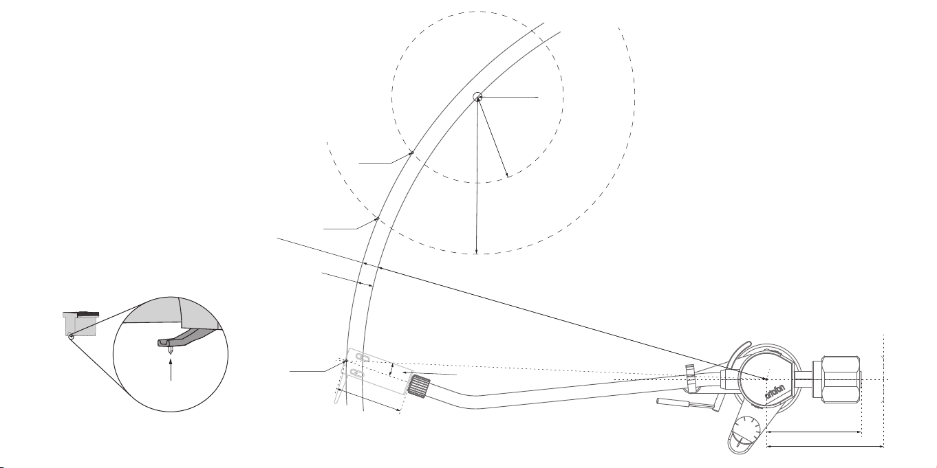
Dimensions – AS-309R
1:4
Null point
Center spindle
R 6
6
R 120.9
Figure 5
Stylus point
E
f
f
e
c
Stylus point
Null point
t
ive
le
n
gt
h
:
3
2
3.
5
m
m
O
ve
r
h
a
n
g
1
2.
5
Mounting dis
t
ance:
3
1
1 mm
1
6
.
7
O
f
fs
et
a
n
g
l
5
°
5
2
mm
e
70.5 mm
Maximum elongation: 90 mm
9
Page 9

Specifications – AS-309R
Arm base
• Arm base fixing screw position: 40 mm in diameter from the center
of the base.
• Three screws are equally spaced at 120°.
Ø3.2
Ø18
Ø40
Ø54.6
Figure 6
10
Ton ea rm
• Mounting distance: 311 mm
• Effective length: 323.5 mm
• Overhang: 12.5 mm
• Offset angle: 16.75°
• Stylus point to the rear end of the headshell: 52 mm
• Tonearm geometry: Baerwald alignment (IEC recommendation, the null
point is 66 and 120.9 mm)
• Arm shaft diameter: 18 mm
• Recommended arm shaft hole diameter: 22 mm
• Cartridge weight: 18 to 26 g (with standard weight, including shell)
• Cartridge weight: 26 to 38 g (with heavy weight, including shell)
• Tonearm weight: 680 g / 730 g standard weight/heavy weight
• Height above mounting sur face: 59 – 79 mm (up to top of the tonearm)
• Counterweight radial clearance: 85 mm for standard weight; 93 mm for
heavy weight (measured from pivot point)
• Distance from mounting surface to top of platter: 20 – 48 mm
• Effective arm mass: 11 g
Page 10

Packing list – AS-212R and AS-309R
To securely remove the arm from the form, please hold
the lower base of the arm.
After unpacking your tonearm, immediately confirm that the following
accessories are included. We recommend keeping the packaging, which
will be needed when transporting the product safely.
• Tonearm
• Standard counterweight
• Heavy counterweight
• Arm base
• Tonearm base template
• Tonearm cable
• Arm base mounting screw/Hexagonal wrench set
- Round countersunk Phillips-head wood screws: 3.1 x 20 mm long
(3 pcs.)
- Round countersunk Phillips-head screws: M3 x 30 mm long (3 pcs.)
- Round countersunk Phillips head screws: M3 x 20 mm long (3 pcs.)
- Hexagon nut: M3 (3 pcs.)
- Flat washers: M3 (3 pcs.)
- Hexagonal wrench: 1.5 mm (1 pcs.)
- Hexagonal wrench: 2.0 mm (1 pcs.)
• Paper mounting template
• Userguide (this manual)
• Product warranty card
• Cartridge alignment tool
• Guide pin adaptor + guide pin
11
Page 11

Guidelines for tonearm care maintenance
and warranty protection
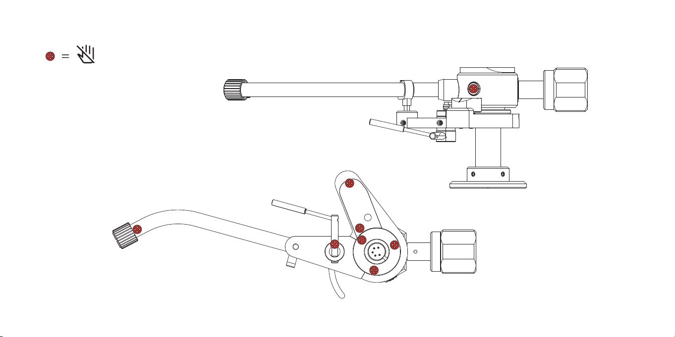
Do not remove or adjust the bearings on the
tonearm pivot assembly. They are factory adjusted to
exacting specifications, and any changes will result in
malfunctioning of the arm and will void the warranty.
Note: When handling the tonearm, ensure it is securely
fastened to the armrest, and never handle or carry the
arm by the arm tube. Do not transport the arm with the
counterweight attached.
12
Do not adjust
Figure 7A
Page 12
Do not adjust
Figure 7B
13
Page 13
How to setup your tonearm
Mounting the arm base
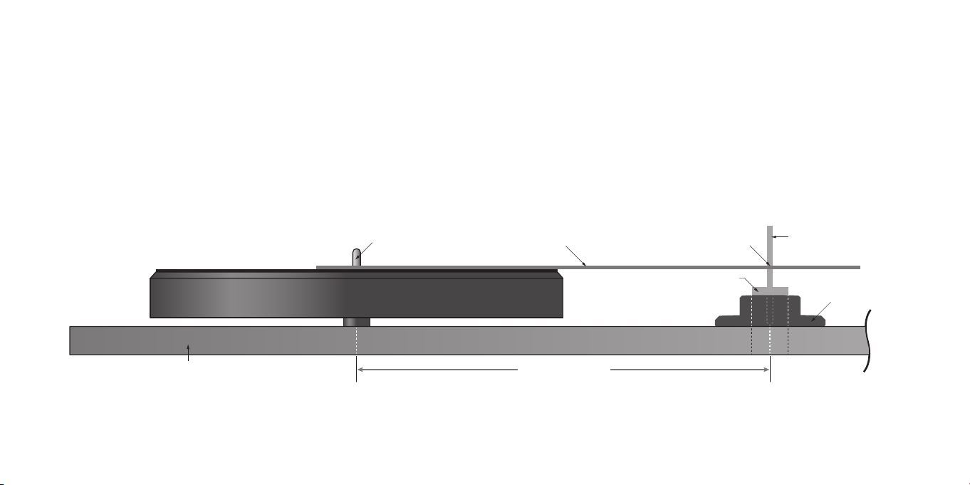
1. Insert the metal guide pin into the hole on the guide pin adapter
(the plastic base) to assemble the guide pin adapter.
2. Insert the guide pin adaptor in the hole for the tonearm shaft and secure
it with one of the set screws.
Turntable spindle
Turntable plinth (or armboard) Mounting distance
14
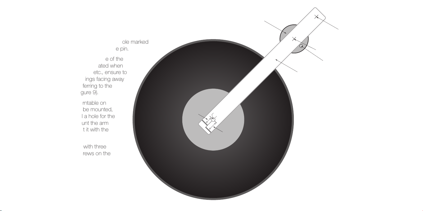
3. Place the spindle hole of the supplied Paper Mounting Template onto
the turntable spindle and determine the position of the arm base (Figure
8 and 9).
Mounting template
The hole of template ma rked
AS-212R or AS-309R
Guide pin adapter
Guide pin
Tonearm base
Figure 8
Page 14
Mounting the arm base (continued)
3. Place the Paper Mounting Template hole marked
“AS-212R or AS-309R” on the guide pin.
4. Since the set screw on the side of the
arm base is frequently operated when
adjusting the arm height, etc., ensure to
install the screw openings facing away
from the platter by referring to the
position example (Figure 9).
5. Depending on the turntable on
which your arm is to be mounted,
you may need to drill a hole for the
tonearm shaft to mount the arm
base and then mount it with the
appropriate screws.
6. Mount the arm base with three
suitable mounting screws on the
plinth or armboard.
12.5
Tonearm base
The hole for turntable spindle
Overhang
18
AS-212R
AS-309R
The hole of template marked AS-212R
Mounting template
The hole of template
marked AS-309R
3 x M3 Screw Hole
Figure 9
15
Page 15
Fitting the arm
Fitting the cartridge
1. After attaching the arm base,
it is possible to pass the
supplied phono cable
or your phono cable
(compatible with phono
5-pin terminal) through
the hole in the center
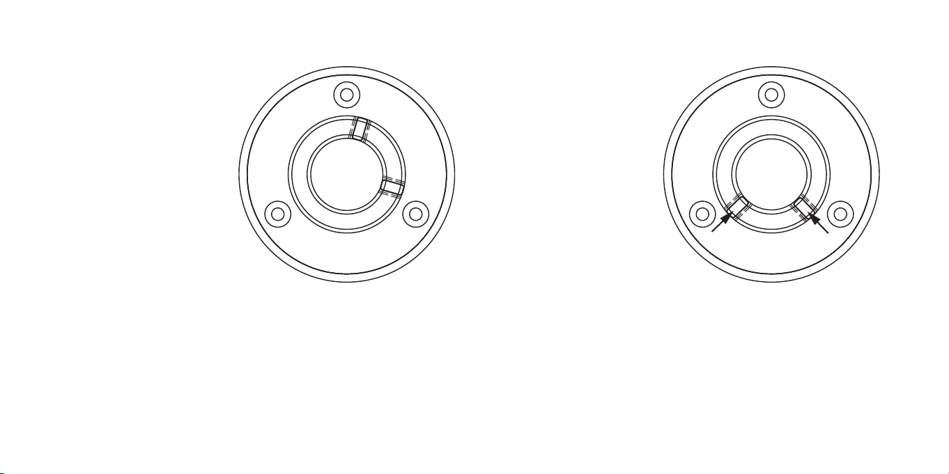
of the base*. Connect
the phono cable to the
tonearm while holding it
with one hand. Connect
the tonearm cable to the
connector inside the bottom of
the arm shaft. Make sure to align
the pin on the cable with the slot on
the bottom of the arm shaft.
If you are more confident with mounting the cables after mounting the
tonearm, it’s possible to wait.
2. Temporarily tighten the arm shaft to the base at an appropriate height.
Only one of the set screws should be lightly tightened for temporary
fixing.
16
Figure 10 Figure 11
1. After fixing the shaft, ensure
the tonearm is locked in
to the arm rest, and then
attach the headshell with
the cartridge attached
to the headshell
connector. Remember
to keep the stylus guard
on the cartridge.
a. Ensure your cartridge
is mounted on the
headshell with the stylus
point at a 52 mm distance
to the end of the headshell to
achieve correct Baerwald alignment
(Figure 2 and 5).
b. Mount the cartridge with the headshell on the tonearm.
Page 16

Adjusting the arm height and swing angle
(without counterweight)
1. Lower the cartridge on the platter’s outer edge and check if the
bottom of the tonearm is parallel to the platter surface.
For this initial alignment, we need to keep the stylus guard on.
2. If they are not parallel, return the tonearm to the arm rest, loosen the
set screws on the arm base, adjust the height of the arm shaft fixing
position, and check again.
3. To control the swing angle, gently swing the tonearm toward the
plat t e r.
4. Check if the arm pipe contacts the arm rest when the tip of the
headshell is placed near the outer circumference of the platter (two
points indicated by the circles in Figure 12)
5. If there is contact, loosen the set screws on the arm base, adjust the
arm body outward, and then re-tighten it. Be careful not to change
the arm height of the tonearm while adjusting the swing angle.
Please notice that further adjustments might are needed after
adjusting the tracking force.
Figure 12
17
Page 17

Mounting the counterweight
Vertical adjustment
1. Mount the counterweight to the shaft of the rear arm, place the side
with the numbers towards the tonearm pivot, and turn it while giving it a
slight push until it catches and moves back and forth when rotated.
Horizontal adjustment
1. Remove the car tridge stylus guard and lower the arm lift. From this
point on, the stylus tip and cantilever at the end of the cartridge will be
exposed, so be careful not to damage them while making adjustments.
2. Remove the tonearm from the arm rest and hold the cartridge up with
one hand.
3. In order to perform the zero balance adjustment, turn the entire
counterweight (both the tracking force scale and the black weight itself)
and balance the tonearm until it floats.
4. After confirming that the tonearm is balanced, return the tonearm to the
arm rest.
5. Align the “0” on the tracking force scale with the white line drawn at the
top of the weight shaft without turning the weight itself. This completes
the zero balance adjustment.
18
1. Adjust the value of the tracking force to the white line at the center of
the weight shaft within the value of the recommended tracking force
specified in the official cartridge specifications.
2. To control the adjustment, use a stylus pressure gauge (Ortofon DS-3)
to check the needle pressure.
3. Place a record on the turntable.
4. Lower the cartridge on the outer edge of the record and check if the
bottom of the tonearm is parallel to the record surface.
5. If not parallel, please adjust the tonearm height while checking the
swing angle of the tonearm.
Lift height
1. In most cases, no adjustment is necessary, but to control the lift height,
raise the arm lift and move the stylus to the middle of the record.
Page 18

2. The tonearm should be slightly above the parallel position, not too high
or too low. If the distance between the needle tip of the car tridge and
the record sur face is too high or if the distance is so low that the needle
tip almost touches the record, even when the lifter lever is raised, return
the tonearm to the arm rest, loosen the tonearm lift fixing screw to move
the lifter cylinder up and down.
Adjusting anti-skating
When a vinyl record spins, the stylus riding in the groove is pulled inwards
toward the center of the vinyl, causing a greater stylus pressure against
the inside wall of the groove than against the outside wall. The anti-skating
mechanism incorporated in the tonearm will neutralize this.
1. Adjust anti-skating by turning the anti-skating knob on the tonearm.
Each increment on the knob responds roughly to 0.5 g. The force is
applied by turning clockwise. Normal anti-skating is set at the same
value as the vertical tracking force.
2. To determine the perfect value, use an Ortofon Test Record to compare
the two channels.
Your tonearm is now set up and ready to use.
Follow the QR code for setup and support.
19
Page 19

Scan and follow the QR code for setup
and support or find more information on
www.ortofon.com/support
Ortofon A /S | Stavangervej 9 | DK-4900 Nakskov | Denmark | [email protected] | www.ortofon.com
07-2023/5-8 00174-12
 Loading...