

Page 1
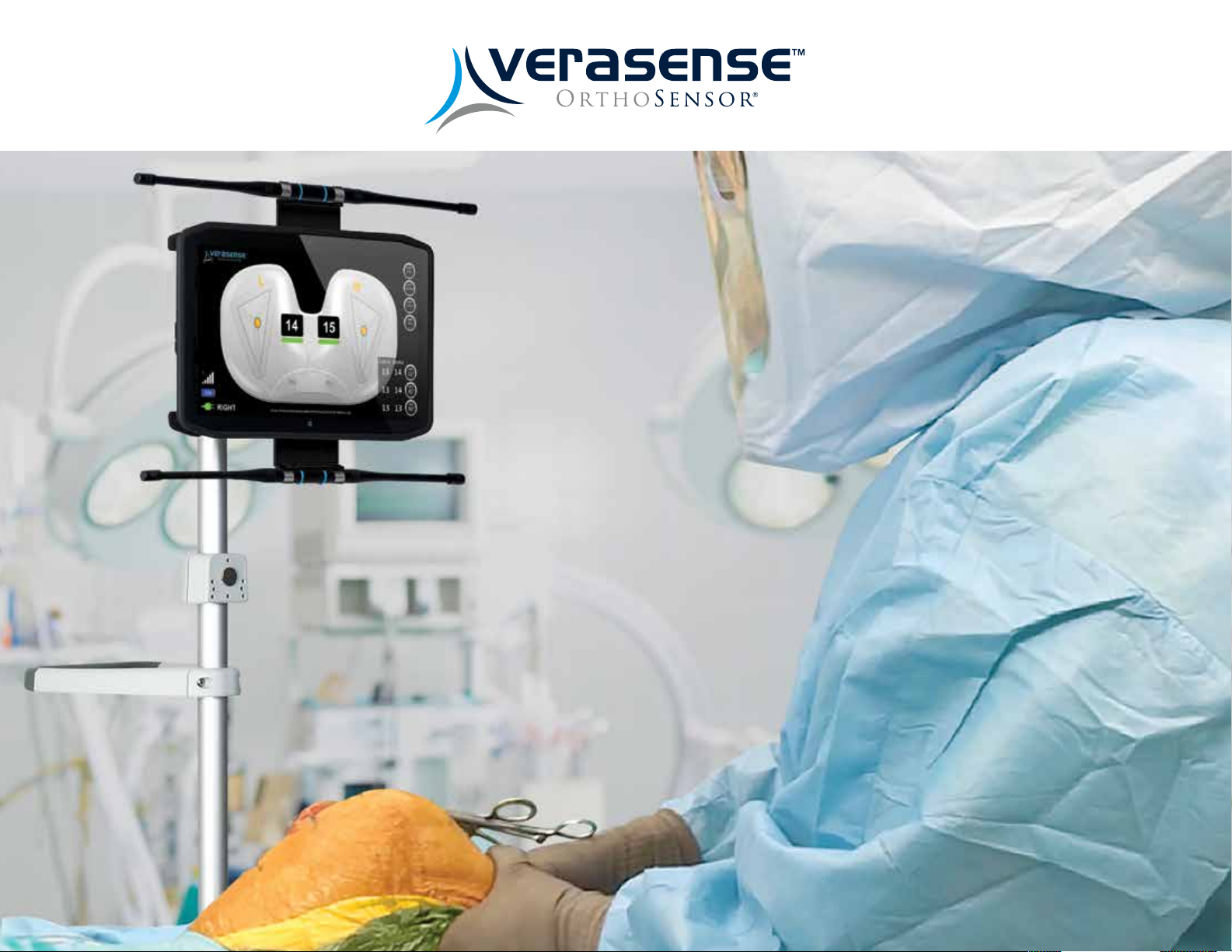
VERASENSE USER GUIDE
1
12/2018 LB-5092 Rev. 2
12/2018 LB-5092 Rev. 2
VERASENSE OrthoSensor.com
Page 2

12/2018 LB-5092 Rev. 2
Page 3
VERASENSE USER GUIDE
TABLE OF CONTENTS
VERASENSE Overview 4
Linkstation Mini With 5
Integrated Antenna Option Overview
Linkstation Mini Evaluation Kit Overview 6
VERASENSE Software Application Overview 7
Getting Started 8
Transceiver Setup 9
Surgeon Selection 1 1
VERASENSE Activation 12
Calibration Sequence & Leg Selection 13
Verify VERASENSE Activation 14
Active Monitoring Screen 15
VERASENSE Insertion 16
Assessing Loads 17
Image & Data Capture 18
Calibration Indicators 19
Understanding Balance 20
VERASENSE Re-Zero Load 22
Kinetic Tracking* 23
Cementing 24
Shutting Down VERASENSE 25
Shutting Down the Linkstation Mini 26
and Linkstation Mini Evaluation Kit
Warning & Dialog Messages 27
Troubleshooting 29
Cleaning & Care 30
Additional Features 3 1
Options Menu 32
Display Available Menus 33
OrthoLogIQ Mode (“IQ Mode”) 34
WiFi Connection Setup 35
Selecting the Open Network 36
Keyboard Hot-Keys 37
Balance Soft-Tissue 2 1
VERASENSE OrthoSensor.com
3
12/2018 LB-5092 Rev. 2
Page 4
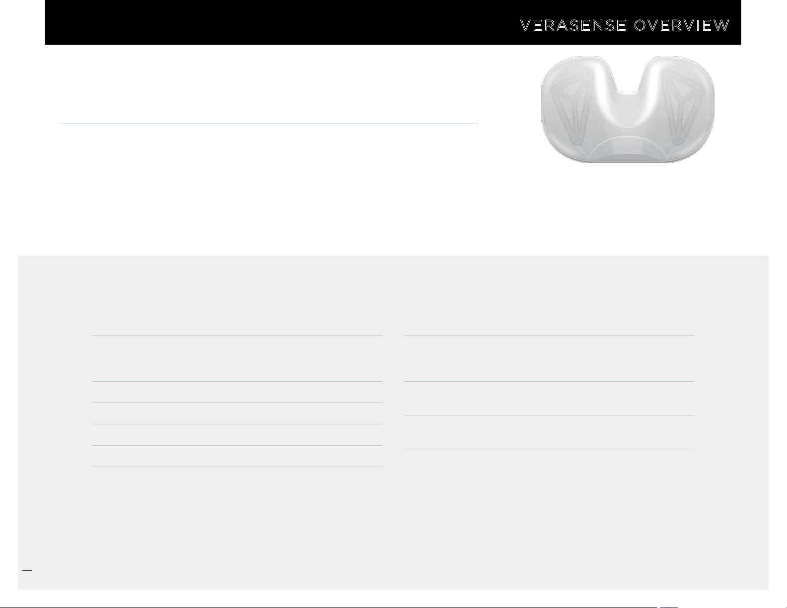
OrthoSensor’s VERASENSE delivers evidence-based data wirelessly to
an intra-operative monitor that enables surgeons to make informed
decisions on soft tissue balance and implant position in real time.
VERASENSE utilizes proprietary sensor technologies to transmit compartmental
load data wirelessly. This enables surgeons to make informed decisions regarding
soft tissue balance, and implant position with the goal of improving joint
performance, knee kinetics and patient satisfaction.
1-3
As a result, patients whose knees have been balanced through the use of
VERASENSE show statistically significant improvements in joint function, pain,
activity level and patient satisfaction.
VERASENSE KEY PRODUCT FEATURES KEY CLINICAL BENEFITS
VERASENSE OVERVIEW
SENSOR-ASSISTED TKA
VERASENSE enables surgeons to
quantify ligament balance and
improves surgeon skill through
real-time, evidence-based data.
• Provides dynamic intercompartmental loads in the medial
and lateral compartments through full ROM with the capsule
closed and patella reduced
• Kinetic Tracking* feature displays dynamic kinematic tracking
in conjunction with load data to visualize tibiofemoral
articulation through full ROM
• Requires no change in surgical workflow
• Low-cost, single-use disposable sensor
• Compatible with multiple knee implant systems
• Enables intraoperative data capture
1 Gustke K A, Golladay GJ, Roche M, Elson L,
Anderson C. Primary TKA patients with Quantifiably
Balanced Sof t-Tissue Achieve Significant Clinical
Gains S ooner than Unbalanced Patients. Adv
Orthop. 2014:628 695.
5 Lombardi AV, Berend KR, Adams JB. Why knee
replacements fail in 2013: patient, surgeon, or
implant? Bone Joint J. 2014;96-B(11 Supple A):
101-104.
VERASENSE OrthoSensor.com
4
2 Gustke K A, Gollad ay GJ, Roche MW, Jerry GJ,
Elson LC , Anderson CR. In crease d satisfaction
after total knee replacement using sensor-guided
technology. Bon e Joint J 2014;96-B:1333–8.
6 Schroer WC, Berend KR, Lombardi AV, et al. Why
are total knees failing today? Etiology of total
knee revision in 2010 and 2011. J Arthroplasty
2013;28(8 Suppl):116–119.
• Intended to address leading causes of premature implant
failure in TKA: mal-alignment and soft-tissue balance
related complications
4-8
• Dynamic compartmental load data and Kinetic Tracking*
enables evidence-based soft tissue releases to improve
stability
4
• Enables reproducible, teachable surgical technique through
quantifying surgeon “feel”
• Captures intraoperative data for inclusion in patient EMR,
registries or comparative effectiveness studies
3 Gustke, Golladay, et al. A New Method for Defining
Balance: Promising Short-Term Clinical Outcomes
of Sensor-Guided TKA. J Arthroplasty. 2014
May:29(5):955-60.
7 Parratte S, Pagnano MW. Instability after total
knee arthroplasty. J Bone Joint Surg Am 2008; 90:
184-94.
4 Bozic K, Kurtz S, Lau E, et al. The epidemiology of
revision total knee arthroplasty in the united
states. Clin Orthop Relat Res. 2010. 468: 45-51.
8 Rodriguez-Merchan, EC. Instability Following Total
Knee Arthroplasty. HSS J. Oct 2011: 7(3): 273-278.
*For Reference Only
12/2018 LB-5092 Rev. 2
Page 5
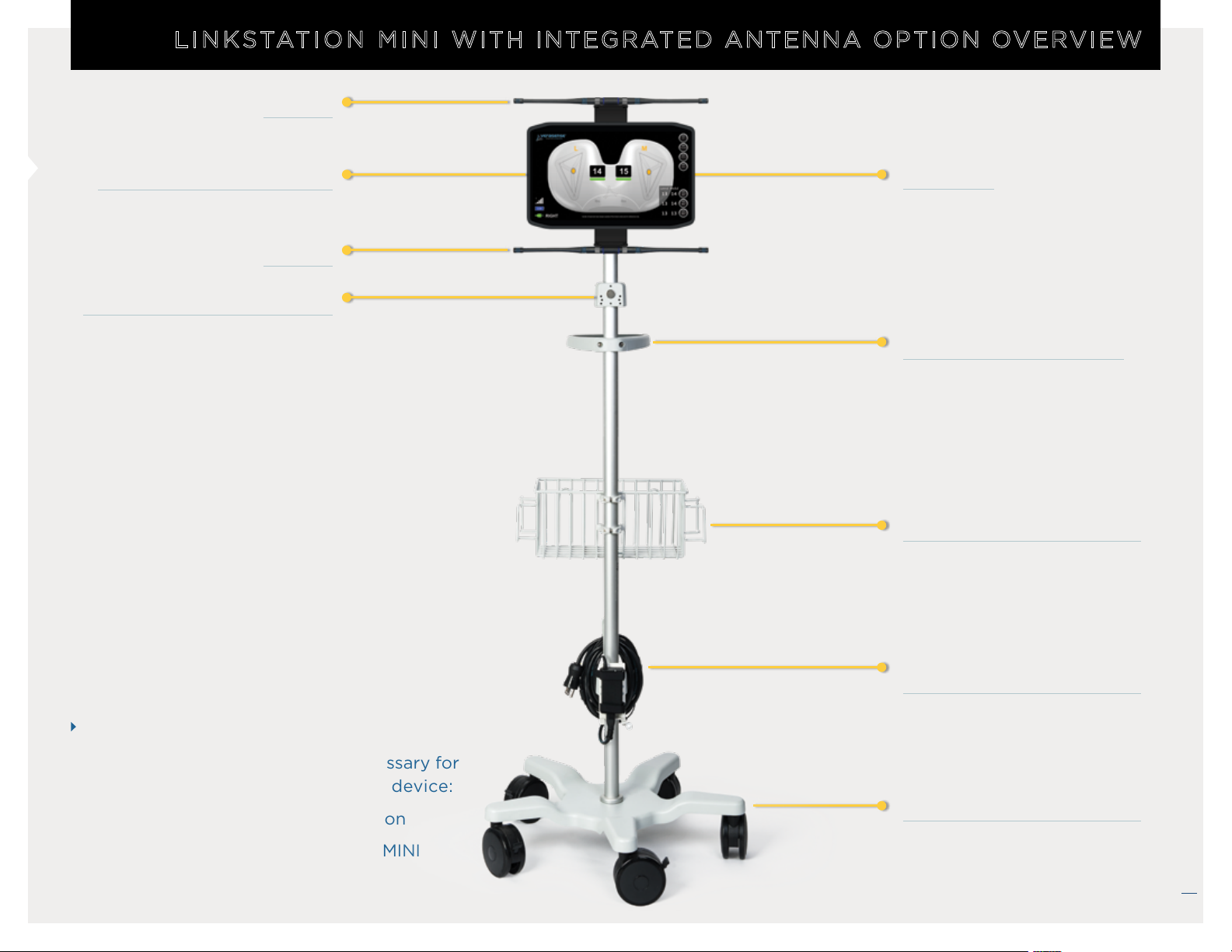
LINKSTATION MINI WITH INTEGRATED ANTENNA OPTION OVERVIEW
Antenna
LinkStation MINI Display Unit
Antenna
VERASENSE Activation Magnet
Transceiver
Easy Grip Transport Handle
VERASENSE Storage Basket
NOTE
The following accessories are necessary for
the operation of the VERASENSE device:
VERASENSE Software Application
LinkStation MINI or LinkStation MINI
Evaluation Kit
Medical Grade Power Cord
with Power Supply Holster
Balanced Rolling Stand
*Center of load and load values outside of
the Green Zone are for reference only.
12/2018 LB-5092 Rev. 2
VERASENSE OrthoSensor.com
5
Page 6

Antenna
Antenna
LinkStation MINI
Evaluation Kit
Display Unit
LINKSTATION MINI EVALUATION KIT OVERVIEW
Transceiver
Transceiver Tripod
Medical Grade Power
Stand
Cord with Power Supply
(NOT DISPLAYED)
NOTE
The following accessories are necessary for the
operation of the VERASENSE device:
VERASENSE Software Application
VERASENSE OrthoSensor.com
6
LinkStation MINI or LinkStation MINI Evaluation Kit
*Center of load and load values outside of the Green Zone are for reference only.
12/2018 LB-5092 Rev. 2
Page 7
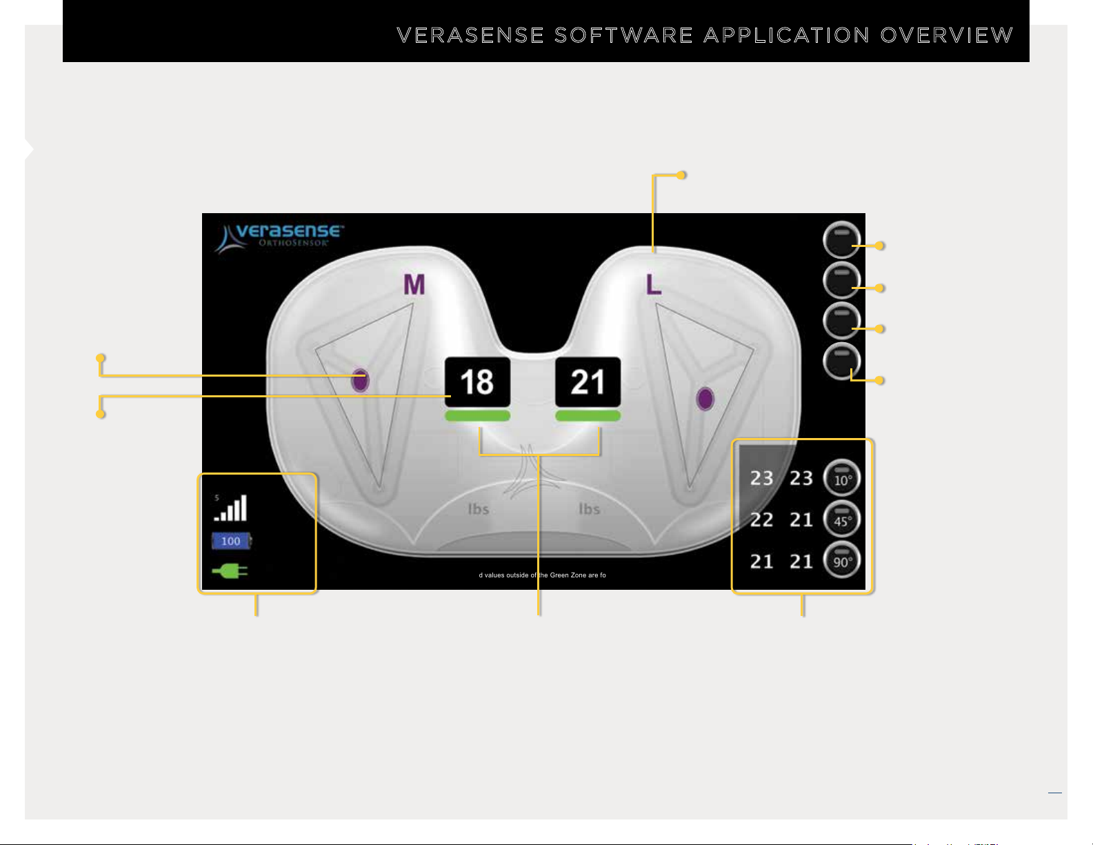
VERASENSE SOFTWARE APPLICATION OVERVIEW
Medial/Lateral Indicators
& Compartment Re-zero
Center of Load
Indicators*
Load Values
LEFT
Center of load and load values outside of the Green Zone are for reference only.
• RF/Bluetooth Signal Strength/
Channel
VERASENSE Calibration
Indicators
EXIT
OPTIONS
TRACK
ZERO
Medial Lateral
Positional Data
Capture Table
Exit VERASENSE
Software Application
Options Menu
Kinetic Tracking*
Re-Zero
VERASENSE
•
VERASENSE Battery Life
• Tablet AC/DC
• Surgical Side Indicator
*Center of load and load values outside of the Green Zone are for reference only.
12/2018 LB-5092 Rev. 2
VERASENSE OrthoSensor.com
7
Page 8
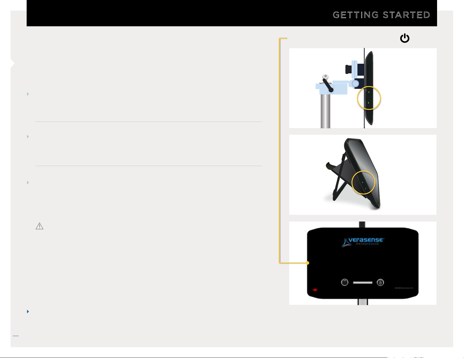
POWERING ON THE LinkStation MINI
STEP 1
To turn on the LinkStation MINI or LinkStation MINI Evaluation Kit, press
the power button located on the left side of the Display Unit.
STEP 2
The VERASENSE Software Application will automatically startup
once the Display Unit is powered on.
STEP 3
GETTING STARTED
DISPLAY UNIT POWER BUTTON
LINKSTATION MINI
The plug-shaped AC/DC Power indicator on the bottom left of the screen
will show whether the tablet is plugged in and running on AC power or if
it is unplugged and running on DC battery power.
LINKSTATION MINI
EVALUATION KIT
CAUTION It is recommended to always plug in the Display Unit and
operate the system on AC power.
Please activate sensor by placing it on the magnet
(Keep sensor on the magnet until application starts)
Searching for sensors...
Physician Name
Turn OFF
Devices
NOTE
VERASENSE OrthoSensor.com
Place the LinkStation MINI or LinkStation MINI Evaluation Kit on
contralateral side of the operating table for optimal surgeon visibility.
AC/DC POWER INDICATOR
RED = UNPLUGGED (DC)
GREEN = PLUGGED IN (AC)
8
Select
12/2018 LB-5092 Rev. 2
Page 9
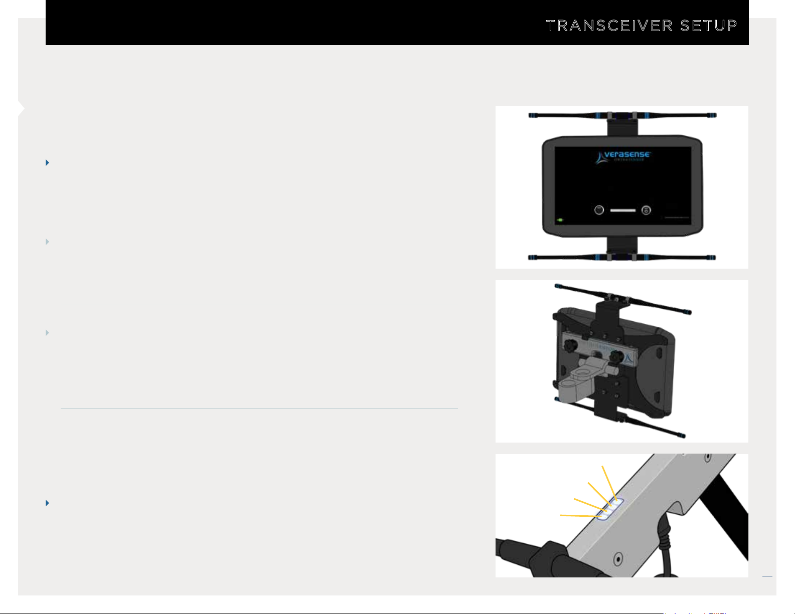
TRANSCEIVER SETUP
TRANSCEIVER SETUP
NOTE The VERASENSE for Zimmer Biomet Persona communicates
with the LinkStation MINI via Bluetooth and the transceiver setup is
not required.
LINKSTATION MINI WITH INTEGRATED ANTENNA OPTION
STEP 1
Ensure the Transceiver Antenna mounting brackets are securely fixed to the
back mounting plate of the Display Unit. Also ensure the Transceiver
housing is properly fixed to the top mounting bracket.
STEP 2
Ensure the Transceiver cable is connected to the USB port on the right of
the Display Unit and firmly connected to the Transceiver. Also confirm both
antenna cables are securely connected to the Transceiver and the top and
bottom mounted Antennas.
Please activate sensor by placing it on the magnet
(Keep sensor on the magnet until application starts)
Searching for sensors...
Physician Name
Turn OFF
Select
Devices
NOTES
1. LED (1) and LED (2) indicate communication between the
Transceiver and
both LEDs are illuminated.
2. LED (3) and LED (4) indicate the Transceiver is powered on.
VERASENSE. Communication is optimal when
LED (1)
LED (2)
LED (3)
LED (4)
VERASENSE OrthoSensor.com
9
12/2018 LB-5092 Rev. 2
Page 10
TRANSCEIVER SETUP
NOTE The VERASENSE for Zimmer Biomet Persona communicates
with the LinkStation MINI or LinkStation MINI Evaluation Kit via
Bluetooth and the transceiver setup is not required.
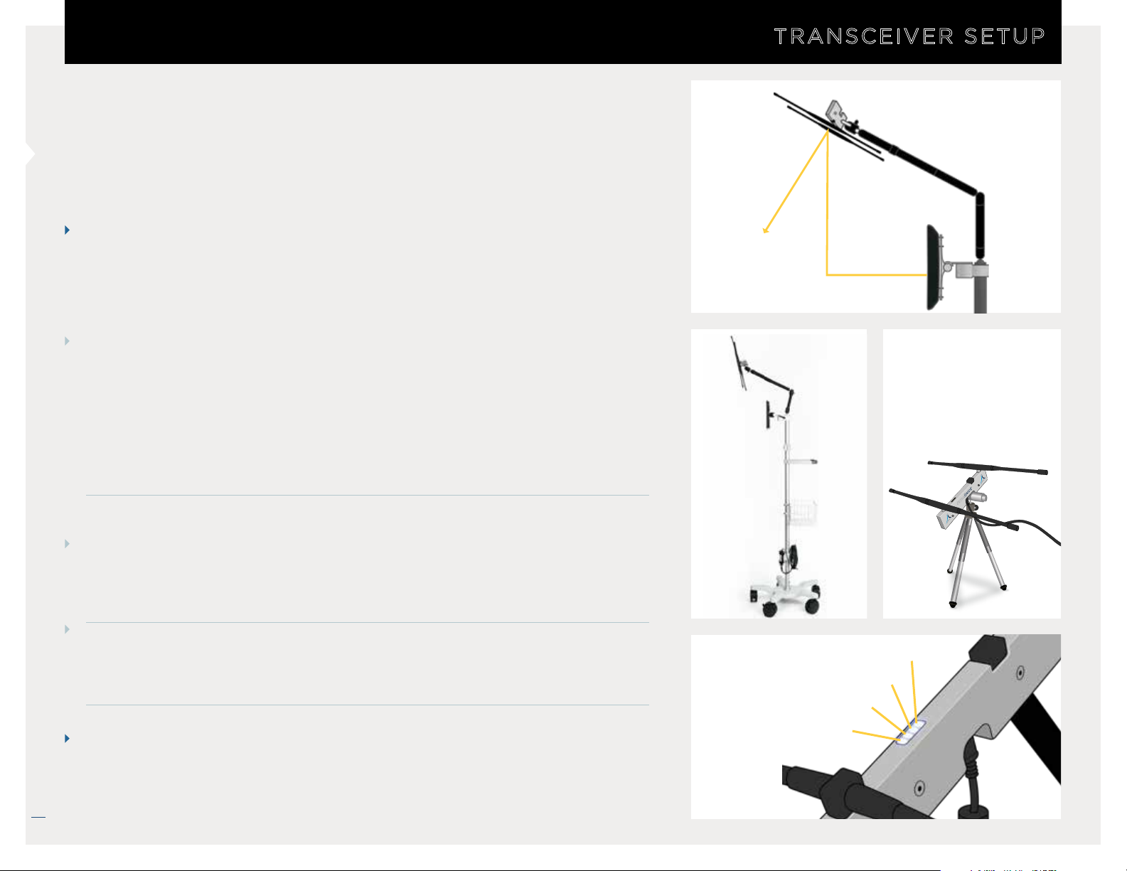
LINKSTATION MINI WITH NON-INTEGRATED ANTENNA
OPTION
STEP 1
See images for ideal Transceiver arm position.
TRANSCEIVER SETUP
LINE OF
SIGHT
>12”
>7”
LINKSTATION MINI
LINKSTATION MINI
EVALUATION KIT
10
• Position antennas at 45° to the floor and at least 12”
(178 mm) out from the display unit.
(305 mm) above and 7”
• Ensure the Transceiver cable is connected to the USB port on the right of
the Display Unit.
LINKSTATION MINI EVALUATION KIT
STEP 1
Attach antennas to Transceiver and mount to tripod. Fully extend tripod
legs prior to use.
STEP 2
Ensure the Transceiver cable is connected to the USB port on the right of
the Display Unit.
NOTES
LED (4)
1. LED (1) and LED (2) indicate communication between the Transceiver and
VERASENSE. Communication is optimal when both LEDs are illuminated.
VERASENSE OrthoSensor.com
2. LED (3) and LED (4) indicate the Transceiver is powered on.
LED (1)
LED (2)
LED (3)
12/2018 LB-5092 Rev. 2
Page 11

SELECT THE SURGEON
STEP 1
Prior to activating VERASENSE, select the surgeon
performing the case.
SURGEON SELECTION
Please activate sensor by placing it on the magnet
STEP 2
Touch the text box to open a drop down menu of surgeon
names.
NOTE: The first name to appear is the surgeon who
was selected for the last use of the VERASENSE Software
Application.
STEP 3
If the surgeon performing the case does not appear, then
select “Surgeon Not Listed” from the drop down menu.
NOTE
(Keep sensor on the magnet until application starts)
Searching for sensors...
Physician Name
WIFI
Physician Name
Doe John MD
Select
Doe John MD
Surgeon Not Listed
Surgeon Not Listed
POWER
POWER
Please contact OrthoSensor Customer Service
to add a new surgeon to the list.
US ONLY 888.75.ORTHO (888. 756.7846)
US AND INTERNATIONAL +1 954.577.7700
VERASENSE OrthoSensor.com
11
12/2018 LB-5092 Rev. 2
Page 12
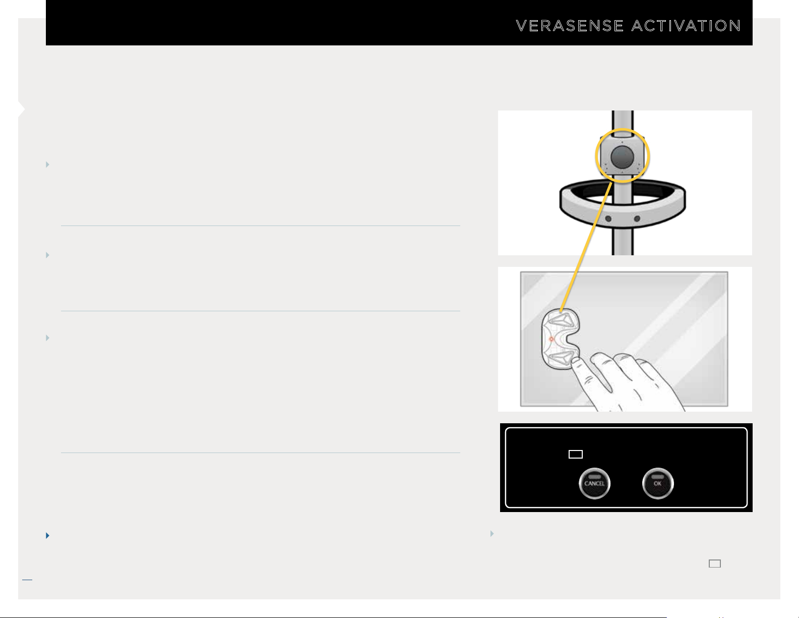
ACTIVATE VERASENSE
STEP 1
Select appropriate VERASENSE size and remove VERASENSE and shims
from outer box.
• DO NOT remove from sterile pouch.
VERASENSE ACTIVATION
12
STEP 2
LINKSTATION MINI
Activate VERASENSE by holding it stationary up against the magnet.
NOTE: For the LinkStation MINI only, the magnet is mounted on the roll stand.
STEP 3
DO NOT REMOVE VERASENSE FROM THE MAGNET UNTIL EACH OF THE
FOLLOWING ACTIVATION STEPS OCCURS:
• An LED light will illuminate in VERASENSE after approximately one (1)
second. The light turns off after approximately four (4) seconds.
• The VERASENSE Software Application will recognize VERASENSE and
initializes communication.
NOTE
VERASENSE OrthoSensor.com
To optimize battery life, do not activate VERASENSE until just before it is
required in the surgical workflow.
VERASENSE has a 40 minute battery life.
If channel switching is enabled, then the
ACTIVE VERASENSE FOUND dialog will display.
Select
OK after verifying serial number (
with package.
Active VERASENSE found
SN
(
1234567890) Connect?
SN
)
12/2018 LB-5092 Rev. 2
Page 13
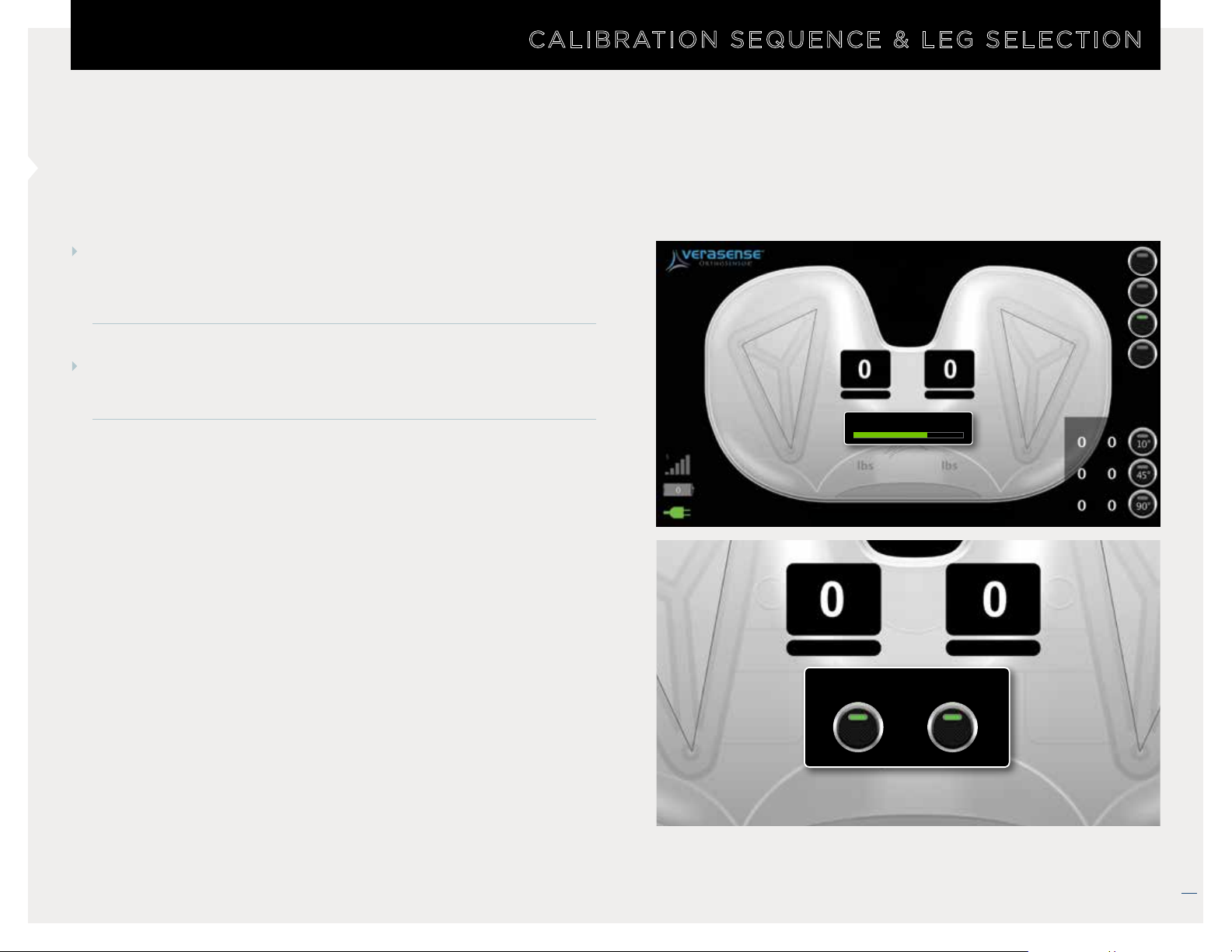
SELECT LATERALITY
CALIBRATION SEQUENCE & LEG SELECTION
STEP 1
Once the calibration sequence is complete, the SELECT LEG
dialog will appear.
STEP 2
Press either LEFT or RIGHT to match the surgery side.
Please wait... Calibrating Sensor
Center of load and load values outside of the Green Zone are for reference only.
Please select leg
EXIT
OPTIONS
TRACK
ZERO
Medial Lateral
* Center of load and load valu es outside of the Green Zone are for reference only.
LEFT RIGHT
VERASENSE OrthoSensor.com
13
12/2018 LB-5092 Rev. 2
Page 14
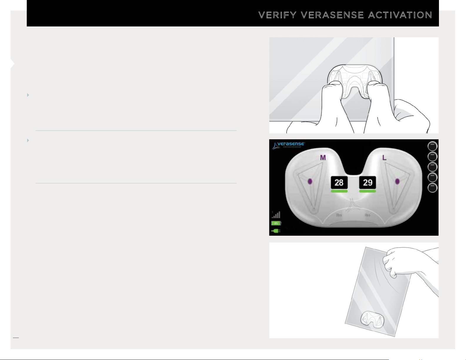
VERIFY VERASENSE ACTIVATION
STEP 1
While in sterile pouch, apply pressure to the VERASENSE
condylar surfaces and confirm that loads display on the
VERASENSE Software Application.
VERIFY VERASENSE ACTIVATION
STEP 2
Once activation is confirmed, open the sterile packaging that
contains VERASENSE and shims and pass into sterile field using
standard sterile technique by hospital personnel.
LEFT
EXIT
OPTIONS
TRACK
ZERO
CAPTURE
Center of load and load values outside of the Green Zone are for reference only.
14
VERASENSE OrthoSensor.com
* Center of load and load valu es outside of the Green Zone are for reference only.
12/2018 LB-5092 Rev. 2
Page 15
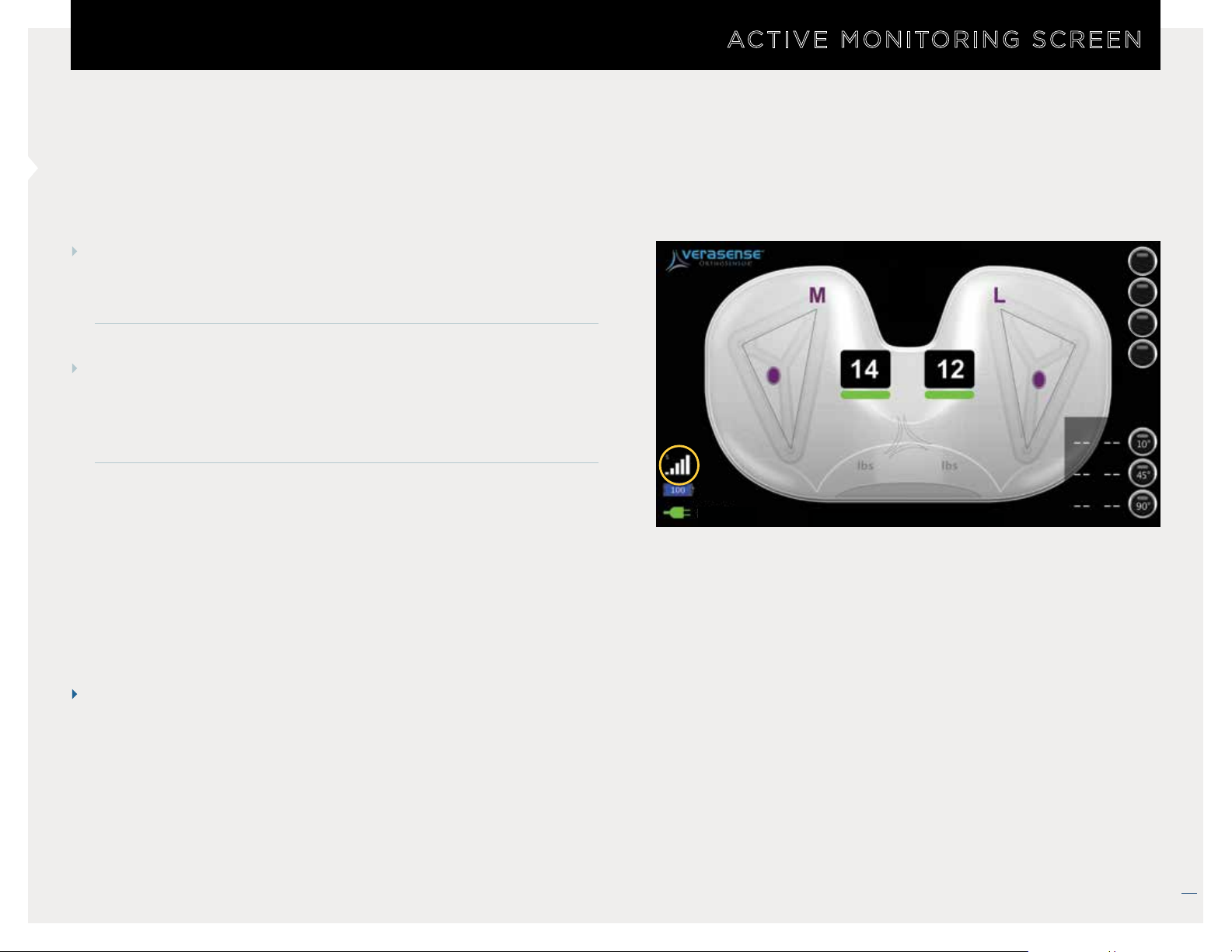
ACTIVE MONITORING SCREEN
ACTIVE MONITORING SCREEN AND COMMUNICATION STATUS
STEP 1
Once VERASENSE is passed into the sterile field, it is ready
for use during the procedure.
STEP 2
Position the LinkStation MINI or LinkStation MINI Evaluation
Kit as close to the sterile boundary as possible and within
direct view of the surgeon.
NOTES
LEFT
EXIT
OPTIONS
TRACK
ZERO
Medial Lateral
Center of load and load values outside of the Green Zone are for reference only.
1. The ACTIVE MONITORING SCREEN is the main screen of
VERASENSE Software Application.
the
2. The Communication Signal Strength Indicator is
located at the bottom left of the screen
VERASENSE
Software Application.
Reposition the LinkStation MINI or or LinkStation MINI
•
Evaluation Kit to troubleshoot poor signal strength.
* Center of load and load values outside of the Green Zone are for reference only.
12/2018 LB-5092 Rev. 2
VERASENSE OrthoSensor.com
15
Page 16
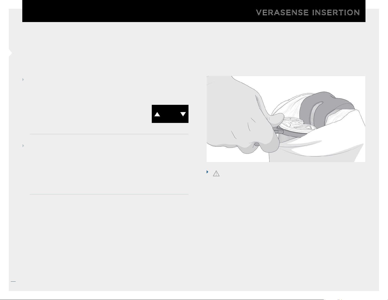
VERASENSE INSERTION & SHIM ASSEMBLY
STEP 1
Determine desired VERASENSE thickness and attach the
appropriate shim as needed.
VERASENSE INSERTION
• NOTE: VERASENSE for Zimmer Biomet
Persona requires the user to input the
selected shim thickness within the
VERASENSE Software Application prior to use.
SHIM
16
STEP 2
Insert VERASENSE.
• In a tight knee capsule, it may be necessary to insert the
trial tibial baseplate and VERASENSE prior to insertion of
the femoral trial. In this instance, reduce the tibia under the
femur, then insert the femoral trial.
CAUTION
DO NOT utilize excessive force or impact VERASENSE
directly with a mallet. Excessive impaction force may
damage or negatively impact function of
VERASENSE.
16
VERASENSE OrthoSensor.com
12/2018 LB-5092 Rev. 2
Page 17
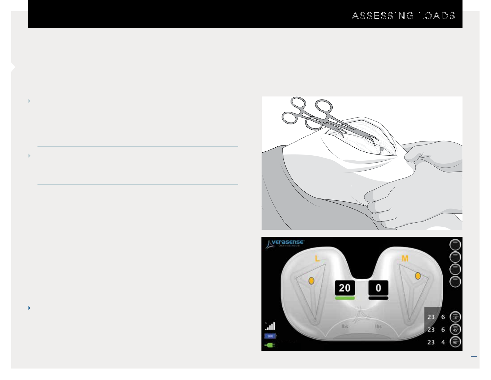
ASSESSING LOADS AND BALANCE
STEP 1
With VERASENSE inserted, the VERASENSE Software
Application will display the position (Contact Points*) and
magnitude of the applied loads in the medial and lateral
compartments.
STEP 2
Data is displayed dynamically through a full range of motion.
ASSESSING LOADS
NOTE
It is recommended to evaluate compartmental loads and
joint balance with the patella reduced and the capsule
closed.
* Center of load and load valu es outside of the Green Zone are for reference only.
RIGHT
EXIT
OPTIONS
TRACK
ZERO
Lateral Medial
Center of load and load values outside of the Green Zone are for reference only.
VERASENSE OrthoSensor.com
17
12/2018 LB-5092 Rev. 2
Page 18
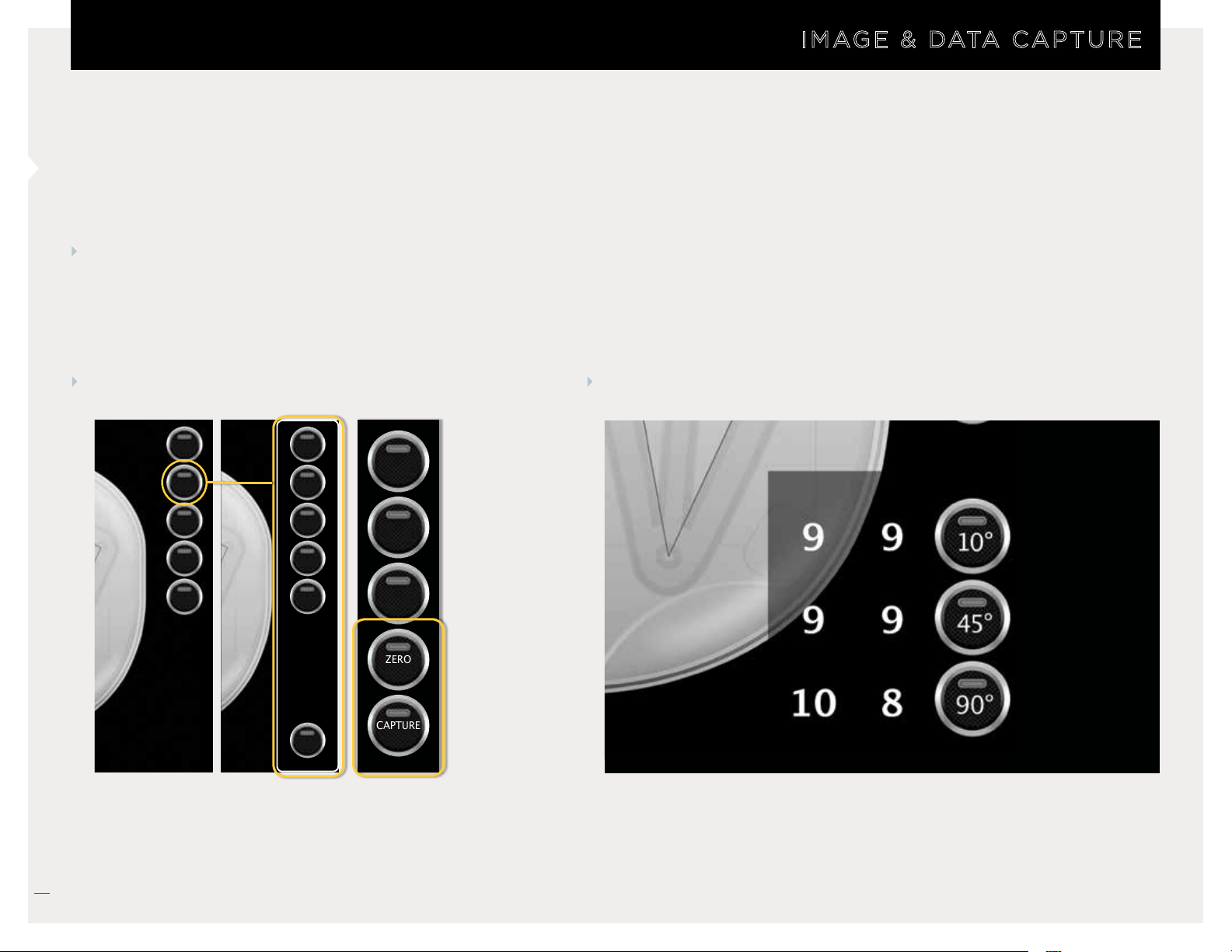
IMAGE & DATA CAPTURE
IMAGE & DATA CAPTURE
TWO WAYS TO CAPTURE SCREEN IMAGES AND DATA
The VERASENSE Software Application shows EITHER the Simple Capture Button OR the Position Capture Table
SIMPLE CAPTURE POSITION CAPTURE
EXIT
OPTIONS
TRACK
ZERO
CAPTURE
• Shown when Position Capture Table isn’t displayed.
LEFT
POSITION
CAPTURE
IQ
INFO
MANUALS
CLOSE
EXIT
Lateral Medial
OPTIONS
TRACK
ZERO
CAPTURE
• Captures screenshot and records load data when 10°, 45°, 90°
BUTTONS are selected.
• Captures screenshot when selected.
VERASENSE OrthoSensor.com
18
12/2018 LB-5092 Rev. 2
Page 19
WHAT YOU NEED TO KNOW:
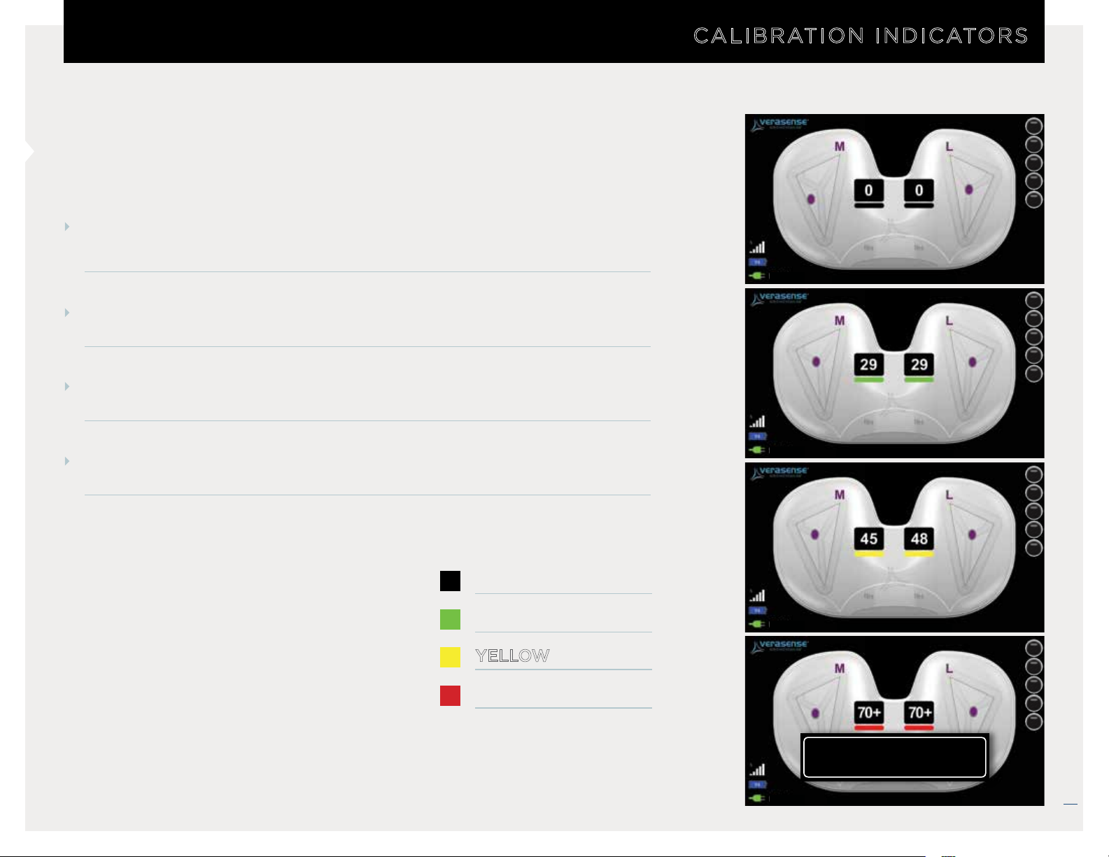
Calibration Indicators are the color bar displays beneath each M/L load value.
• Indicate levels of VERASENSE accuracy throughout loading range.
Center of Load reference points are a consistent color throughout all
loading ranges.
Calibrated load range is within
outside of the GREEN ZONE are for reference only.
GREEN ZONE FROM 5 – 40 LBF. Loads values
CALIBRATION INDICATORS
LEFT
Center of load and load values outside of the Green Zone are for reference only.
EXIT
OPTIONS
TRACK
ZERO
CAPTURE
EXIT
OPTIONS
TRACK
ZERO
CAPTURE
VERASENSE Software Application displays a
message when either side goes into the
VERASENSE OVERLOAD
RED ZONE.
BLACK = 0-4 lbf
GREEN = 5-40 lbf
YELLOW = 41-70 lbf
RED = 70+ lbf
* Center of load and load valu es outside of the Green Zone are for reference only.
LEFT
LEFT
Center of load and load values outside of the Green Zone are for reference only.
Center of load and load values outside of the Green Zone are for reference only.
VERASENSE overload detected,
re-zero recommended.
LEFT
Center of load and load values outside of the Green Zone are for reference only.
EXIT
OPTIONS
TRACK
ZERO
CAPTURE
EXIT
OPTIONS
TRACK
ZERO
CAPTURE
VERASENSE OrthoSensor.com
19
12/2018 LB-5092 Rev. 2
Page 20
UNDERSTANDING BALANCE
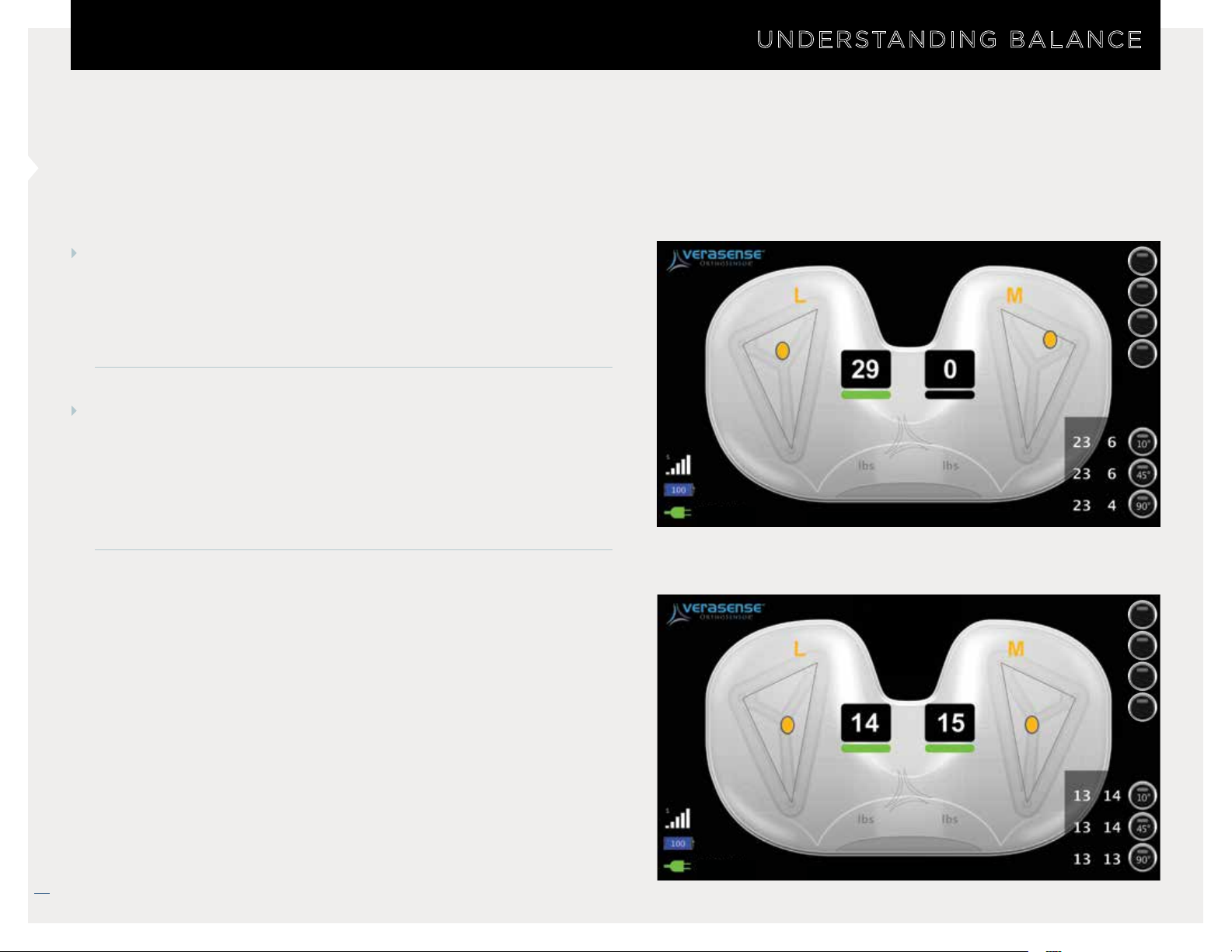
CORONAL BALANCE
UNDERSTANDING BALANCE
UNBALANCED
(Load Difference = 29 - 4 = 25lbf)
EXIT
Clinical research suggests a load differential between the
medial and lateral compartments of
less than or equal to 15 LBF
through the range of motion is indicative of coronal plane soft
tissue balance.*
SAGITTAL BALANCE (CR COMPONENTS)
This is typically determined by a stable end-point during a
posterior drawer test, while not exhibiting gross PCL tension
leading to excessive rollback or anterior lift-off of the tibial
component. The femoral contact points are in the mid-third of
the tibial plateau.*
RIGHT
Center of load and load values outside of the Green Zone are for reference only.
BALANCED
(Load Difference = 15 - 14 = 1lbf)
OPTIONS
TRACK
ZERO
Lateral Medial
EXIT
OPTIONS
TRACK
ZERO
20
Lateral Medial
Roche MW, et al. Dynamic soft tissue balancing in total knee
arthroplasty. Orthop Clin N Am. 2014; 45(2): 157-165
VERASENSE OrthoSensor.com
* Center of load and load valu es outside of the Green Zone are for reference only.
RIGHT
Center of load and load values outside of the Green Zone are for reference only.
12/2018 LB-5092 Rev. 2
Page 21
BALANCE SOFT-TISSUE
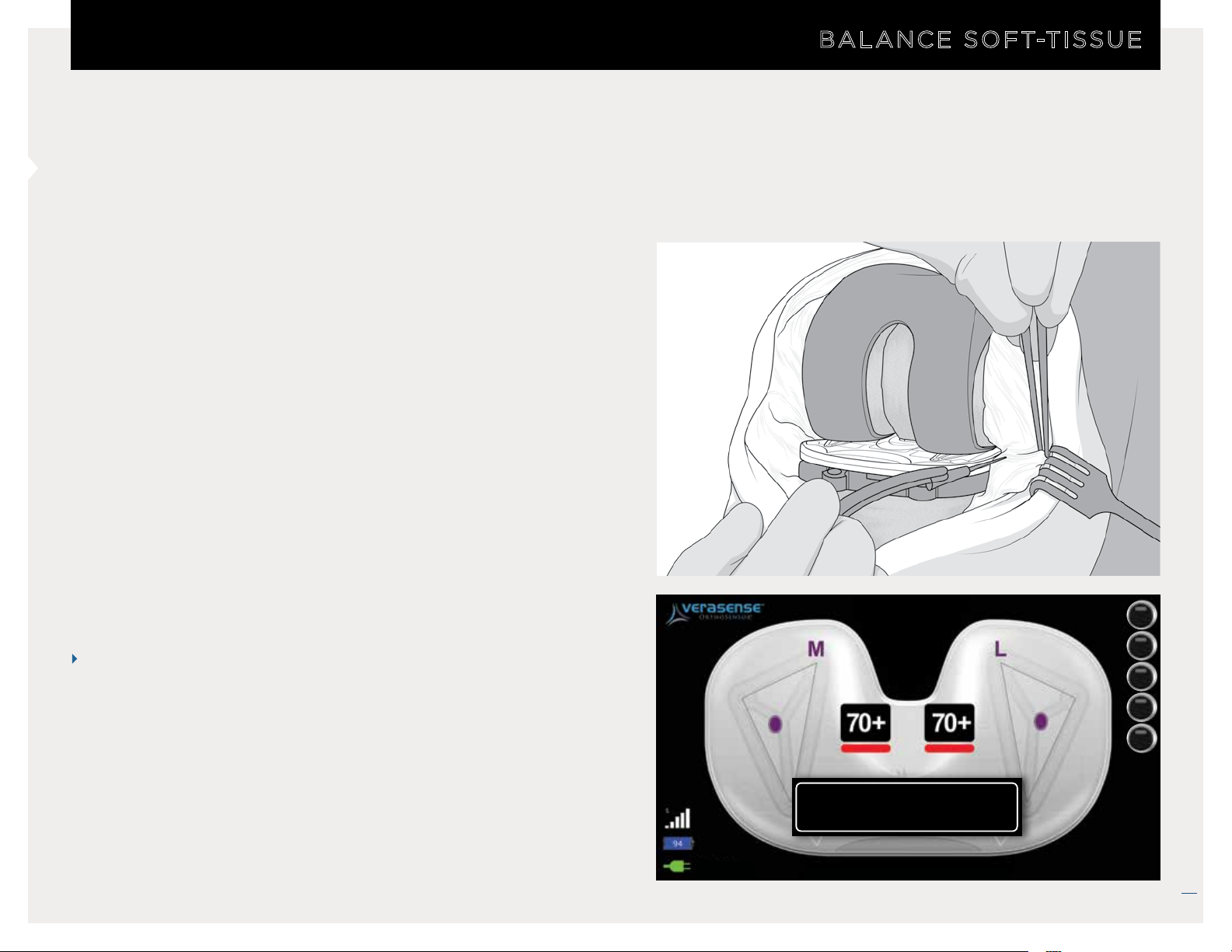
Clinical experience combined with information displayed by the
VERASENSE Software Application may be used to assist decision
making regarding component placement and soft tissue releases
to achieve compartmental balance.
BALANCE SOFT-TISSUE
MCL pie-crusting with an 18-gauge needle
NOTES
1. If VERASENSE indicates a compartmental load in excess of
70lbf, reduce shim size if possible or perform initial releases
to bring the load below 70lbf. Before performing final
release to achieve soft tissue balance, remove
and re-zero.
2. If VERASENSE indicates a compartmental load of less than
5 lbf, increase shim size to generate condylar load.
* Center of load and load values outside of the Green Zone are for reference only.
VERASENSE
LEFT
EXIT
OPTIONS
TRACK
ZERO
CAPTURE
VERASENSE overload detected,
re-zero recommended.
Center of load and load values outside of the Green Zone are for reference only.
VERASENSE OrthoSensor.com
21
12/2018 LB-5092 Rev. 2
Page 22
VERASENSE RE-ZERO LOAD
RE-ZEROING
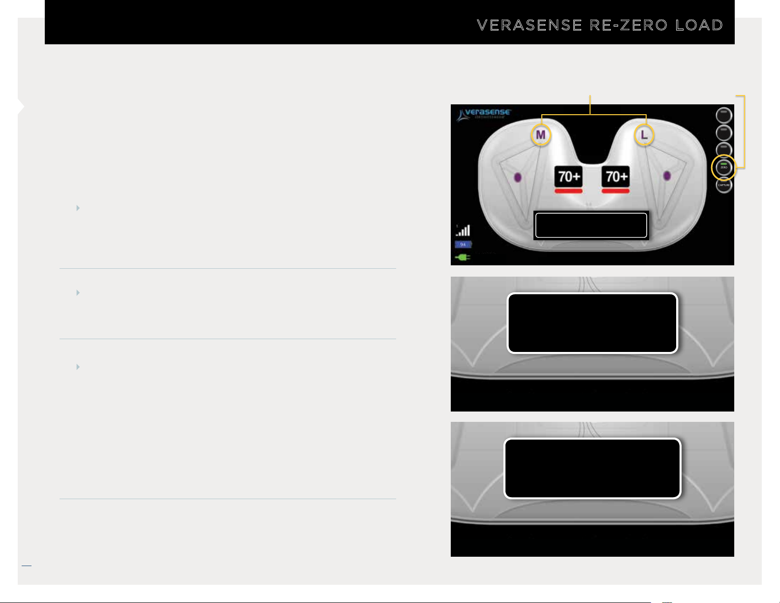
If VERASENSE experiences elevated loads, a re-zero
calibration may be required for accurate load readings. A user
can perform a re-zero in three ways:
MOTION-CONTROLLED RE-ZERO
Hold VERASENSE with superior side (articulating surface)
facing the floor for three (3) seconds. Wait for Re-Zero
Enabled and Re-Zero Completed messages to display.
MENU ZERO BUTTON
Remove loaded VERASENSE and then press the Zero
Button on the VERASENSE Software Application.
COMPARTMENT SPECIFIC RE-ZERO
Compartment Re-Zero
VERASENSE overload detected,
re-zero recommended.
LEFT
Center of load and load values outside of the Green Zone are for reference only.
Re-Zero Enabled
Re-Zero Device
EXIT
OPTIONS
TRACK
ZERO
CAPTURE
22
With the VERASENSE in the joint, apply a varus or valgus
Center of load and load values outside of the Green Zone are for reference only.
thrust to the knee in order to off-load the desired medial
or lateral compartment. Once the VERASENSE surface is
visually unloaded, select the laterality indicator of the
unloaded side to initiate the Re-Zero, repeat the steps on
the opposite side in order to complete the Re-Zero.
NOTE: Compartment Re-Zero is only available with VERASENSE for
Zimmer Biomet Persona.
VERASENSE OrthoSensor.com
Re-Zero Completed
Center of load and load values outside of the Green Zone are for reference only.
12/2018 LB-5092 Rev. 2
Page 23
USING THE KINETIC TRACKING FEATURE
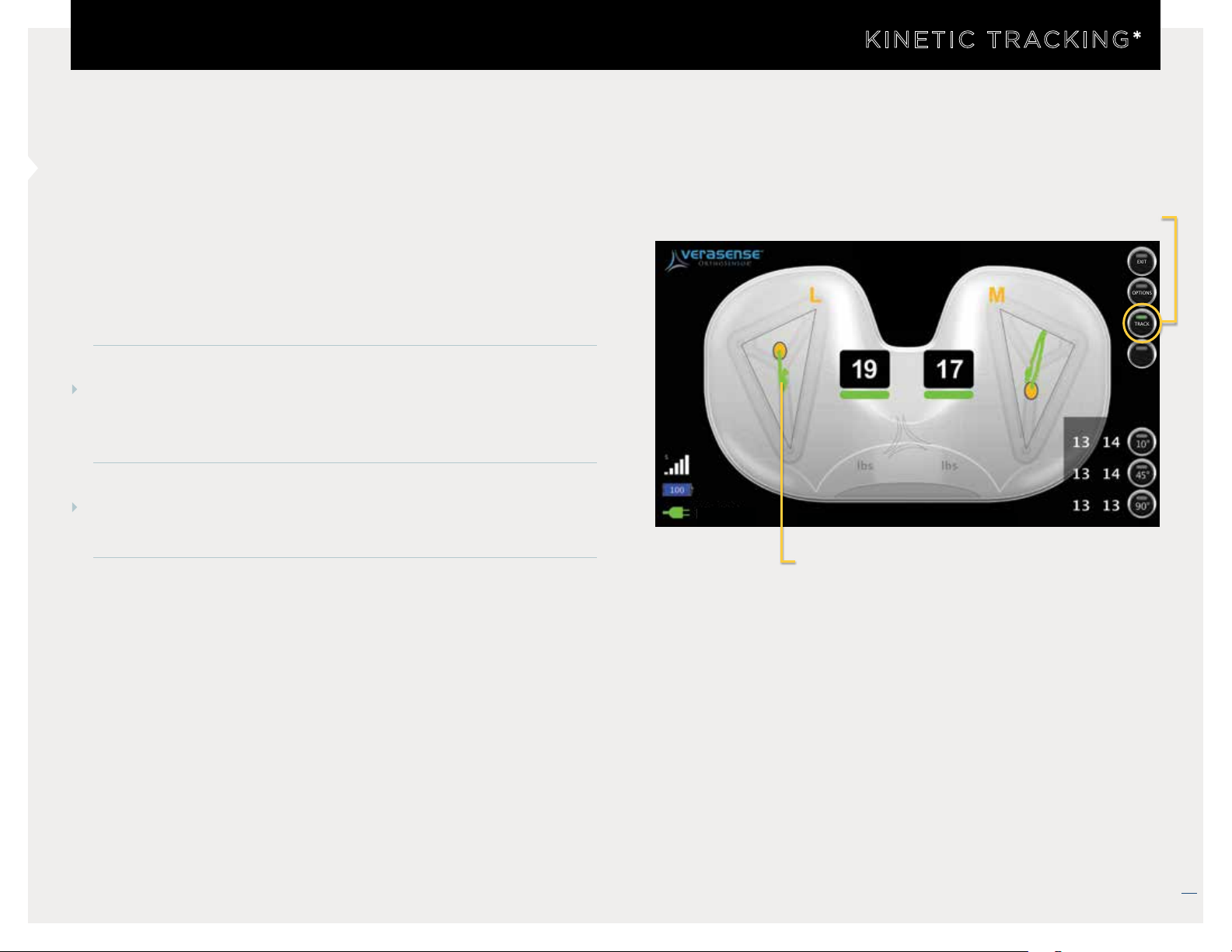
Displays dynamic motion of the knee through the full ROM to
evaluate joint kinetics
• Extension to flexion roll back evaluation, AP drawer test,
Int/Ext rotation laxity, etc.
STEP 1
KINETIC TRACKING*
Press Track to turn on/off kinetic tracking
EXIT
OPTIONS
TRACK
ZERO
Select the Track Button on the VERASENSE Software
Application to enable Kinetic Tracking.
STEP 2
To clear and disable tracking, click the Track Button again.
RIGHT
Center of load and load values outside of the Green Zone are for reference only.
Kinetic Tracks are displayed as
green lines that trace contact
point movement*
Lateral Medial
* Center of load and load values outside of the Green Zone are for reference only.
VERASENSE OrthoSensor.com
23
12/2018 LB-5092 Rev. 2
Page 24
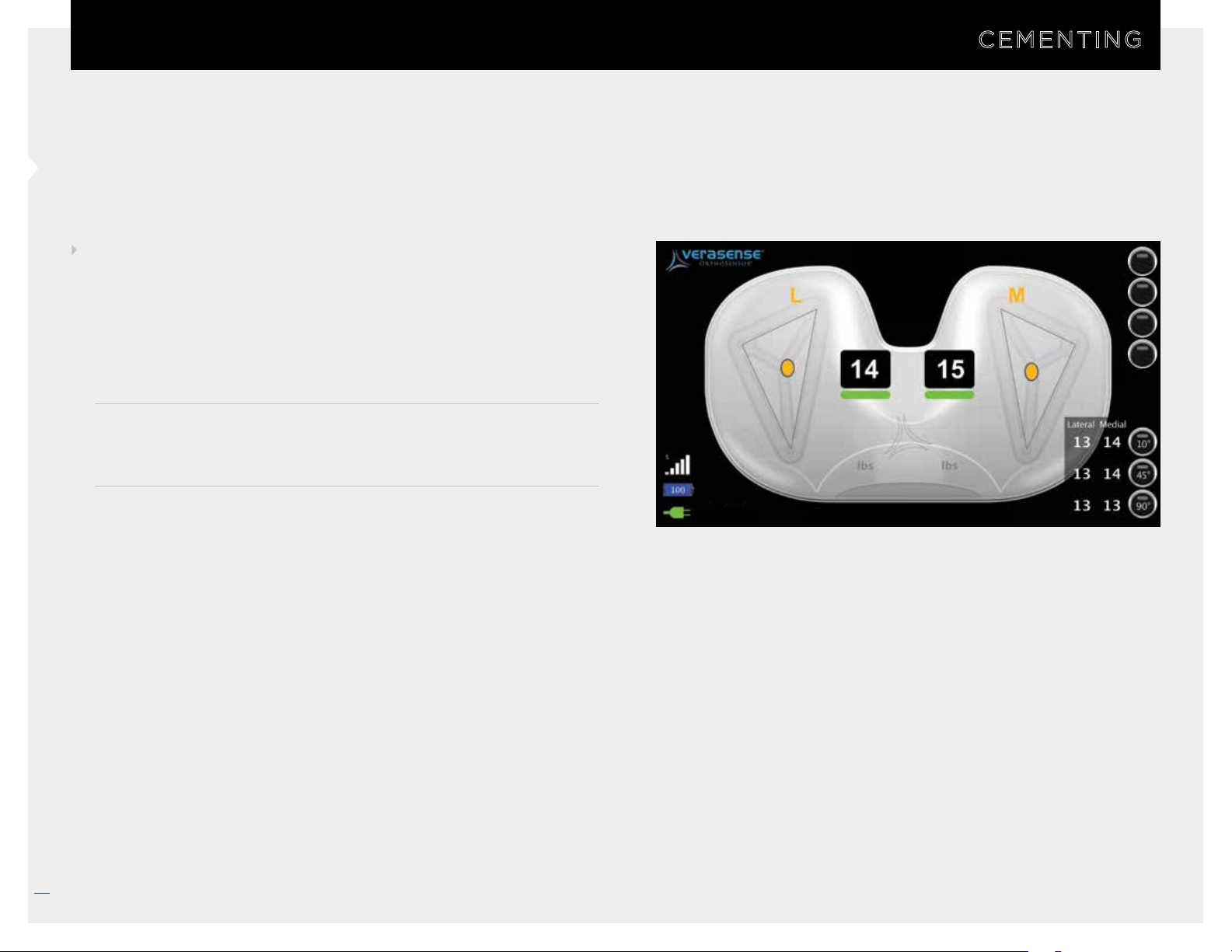
USE OF VERASENSE DURING CEMENTATION
CEMENTING
VERASENSE can be used during the final cementation
process to ensure balance achieved during component trialing
is maintained through the end of the procedure.
• Ensure proper seating of the components, as even a small
amount of residual cement mantle can affect joint balance.
• Assess final poly component thickness for adequate loading.
When impacting the final femoral componets be sure not to
overload VERASENSE. Re-Zero, if necessary.
RIGHT
EXIT
OPTIONS
TRACK
ZERO
Lateral Medial
Center of load and load values outside of the Green Zone are for reference only.
24
VERASENSE OrthoSensor.com
* Center of load and load valu es outside of the Green Zone are for reference only.
12/2018 LB-5092 Rev. 2
Page 25
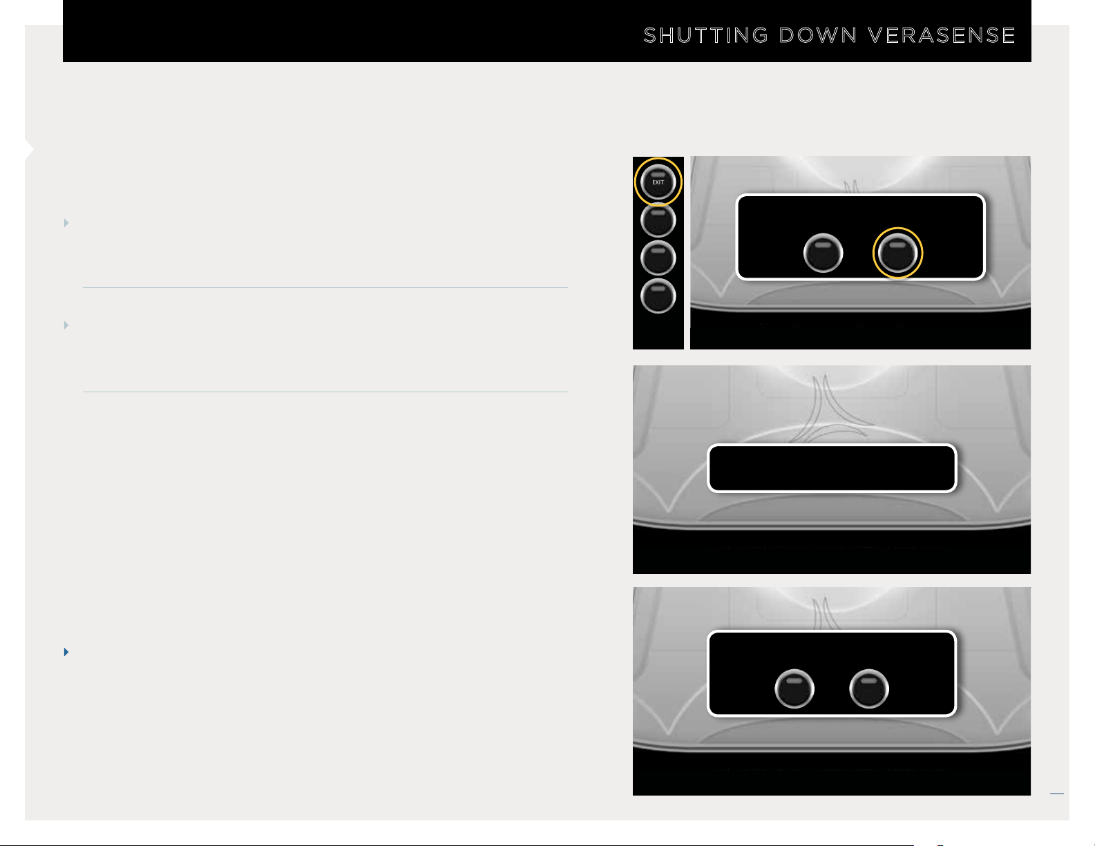
VERASENSE SHUT DOWN
SHUTTING DOWN VERASENSE
EXIT
STEP 1
To turn off VERASENSE when the procedure is complete, press the
EXIT button in the top right corner of the Active Monitoring screen.
STEP 2
Confirm exit on the pop-up window by pressing OK. The “Shutting
down VERASENSE” dialog box will open.
OPTIONS
TRACK
ZERO
Center of load and load values outside of the Green Zone are for reference only.
VERASENSE connected.
Are you sure you want to exit?
CANCEL
OK
Shutting down VERASENSE...
Center of load and load values outside of the Green Zone are for reference only.
NOTE
Either the RF or Bluetooth Transceiver will communicate with
VERASENSE to power down the device. If communication can no longer
be achieved, the “VERASENSE shutdown failed” box will open. Select
EXIT HOME SCREEN to exit the VERASENSE Software Application.
* Center of load and load values outside of the Green Zone are for reference only.
VERASENSE shutdown failed. Try again?
Exit
Home
Screen
Center of load and load values outside of the Green Zone are for reference only.
RETRY
VERASENSE OrthoSensor.com
25
12/2018 LB-5092 Rev. 2
Page 26
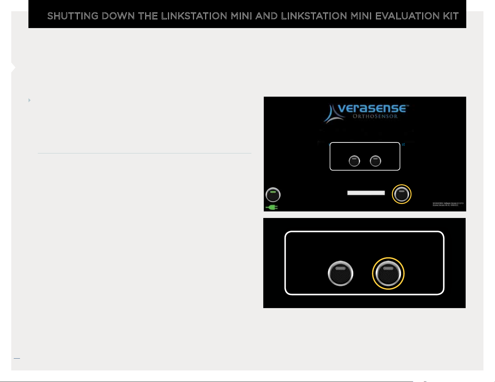
SHUTTING DOWN THE LINKSTATION MINI AND LINKSTATION MINI EVALUATION KIT
LINKSTATION MINI AND LINKSTATION MINI EVALUATION KIT
SHUTDOWN
After the procedure is complete and VERASENSE has been shut
down successfully, shut down the Display Unit by pressing the
POWER BUTTON and then selecting OK.
• This will power the entire Display Unit down.
• In order to restart, the external power button must be pressed.
Please activate sensor by placing it on the magnet
(Keep sensor on the magnet until application starts)
Are you sure you want to shutdown?
Searching for sensors...
CANCEL
WIFI
Surgeon Not Listed
OK
Physician Name
POWER
Are you sure you want to shutdown?
CANCEL
OK
26
VERASENSE OrthoSensor.com
12/2018 LB-5092 Rev. 2
Page 27
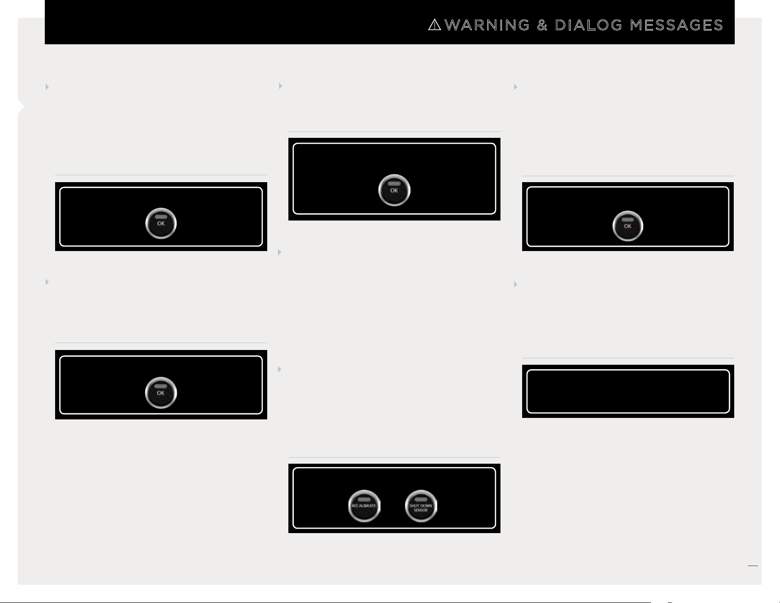
WARNING & DIALOG MESSAGES
VERASENSE ERROR -
UNABLE TO CONNECT
Error during the initial connection with
starting VERASENSE. Typically due to
VERASENSE power loss during
connection.
VERASENSE error. Unable to connect.
INVALID LEG SELECTION
Error message if leg selection is the
wrong side for an asymmetrical
VERASENSE.
Invalid Leg Selection.
RF TRANSCEIVER UNPLUGGED
Transceiver cable disconnected
during active
Please plug it back into a USB port.
VERASENSE
Transceiver is unplugged!
monitoring.
VERASENSE CALIBRATION
TIMEOUT
This message will appear if a calibration
error occurs during Activation of
VERASENSE.
• Select
VERASENSE Software Application
recalibrate VERASENSE prior to
moving to the Active Monitoring
Screen.
• Select
shut down the current VERASENSE
and to exit to the VERASENSE
Software Application Home Screen.
RECALIBR AT E to have the
SHUT DOWN VERASENSE to
VERASENSE CALIBRATION
ERROR
This message will appear if a VERASENSE
Software Application error has occurred
during the initial VERASENSE calibration
while on the Active Monitoring Screen.
VERASENSE Calibration Error.
VERASENSE OVERLOAD
DETECTED
VERASENSE overload condition in loads
exceed 70lbf. Re-Zero should be
performed.
VERASENSE overload detected,
re-zero recommended.
VERASENSE Calibration Timeout.
VERASENSE OrthoSensor.com
27
12/2018 LB-5092 Rev. 2
Page 28
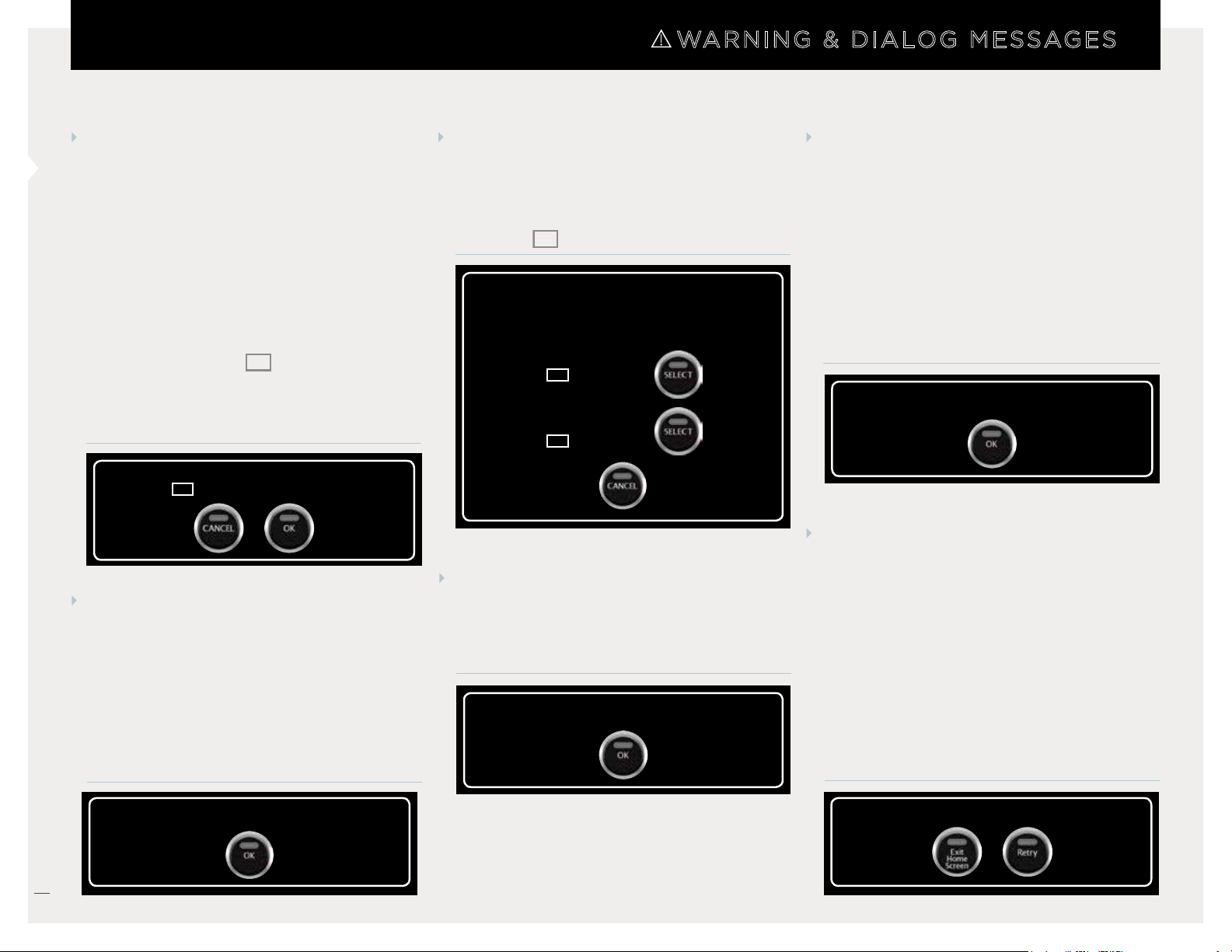
WARNING & DIALOG MESSAGES
ACTIVE VERASENSE FOUND
This message appears when an active
VERASENSE is found. If the VERASENSE
Software Application is enabled with
Channel Switching and the VERASENSE
Software Application detects an active
VERASENSE, the following dialog box
will appear with the active VERASENSE
serial number.
SERIAL NUMBER (SN) VERASENSE.
(The serial number is located on both the
VERASENSE box as well as the Tyvek
Pouch that VERASENSE is in).
Active VERASENSE found
SN
(
1234567890) Connect?
VERASENSE SEARCH - ERROR
This message appears when an error
has occurred while the VERASENSE
Software Application is searching for
active VERASENSE. Select OK and the
VERASENSE Software Application will
reset and re-establish the search for all
active VERASENSE.
MULTIPLE VERASENSE FOUND
VERASENSE selection message when
multiple VERASENSE sensors are active.
Choose desired VERASENSE by serial
number (
Please select VERASENSE or ‘CANCEL’ to wait for
a different VERASENSE to become activated.
SN
) listed on box.
Multiple VERASENSE found
SN
311717036
SN
412938089
VERASENSE DATA TIMEOUT
This message will appear if an error has
occurred when handling measured data
that is being transferred from VERASENSE.
VERASENSE Data Transfer Timeout.
VERASENSE ERROR - UNABLE
TO CONNECT
This message may appear when an error
has occurred during the initial connection
after the identification of VERASENSE
and the VERASENSE Software Application
is unable to properly obtain the
VERASENSE EEPROM data. Typical causes
are due to loss of VERASENSE power
during activation or reception issues.
VERASENSE Error. Unable to connect.
VERASENSE SHUTDOWN FAILED
This message will appear if an error has
occurred when trying to shutdown
VERASENSE from the Active Monitoring
Screen. If
VERASENSE Software Application will
offer additional shutdown attempts. If
EXIT HOME SCREEN is selected then the
VERASENSE Software Application will
close and return to the VERASENSE
Software Application Homepage.
RETRY is selected, the
28
Error during VERASENSE Search. Select ‘OK’ to reset.
VERASENSE OrthoSensor.com
VERASENSE shutdown failed. Try again?
12/2018 LB-5092 Rev. 2
Page 29
TROUBLESHOOTING
TROUBLESHOOTING
VERASENSE
If VERASENSE Light does not turn off during activation:
• Return VERASENSE to the activation magnet to complete
the activation sequence.
If VERASENSE is showing no load values in the knee, or load
values are being shown when it has been removed from the
knee and no load is being applied:
• Re-Zero VERASENSE.
DISPLAY UNIT
If Display Unit will not turn on, or shuts down
inadvertently:
• Ensure the power cord is properly attached to the Display
Unit and plugged into a power outlet.
If Display Unit power button is blinking but nothing is happening:
• The Display Unit is in sleep mode. Press the power button
to wake up the Display Unit.
WIRELESS COMMUNICATION
If Communication is intermittent:
• Reposition the LinkStation MINI or LinkStation MINI
Evaluation Kit as close to the sterile boundary as possible
and within direct view of the surgeon.
• Objects such as OR lights, metal tables and mayo stands,
and people can potentially interfere with communication.
RF Communication:
• Verify USB cable for the Transceiver is securely plugged
into the Display Unit and into the USB port on the bottom
of the Transceiver.
• Ensure antennas on the Transceiver are secure and that the
line of sight between the Transceiver and VERASENSE is
clear.
• All four LED lights on the Transceiver will be illuminated
when VERASENSE is communicating assembly.
ROLL STAND
If Roll Stand will not roll:
• Check to ensure that the breaks on the casters are
disengaged.
(FOR LINKSTATION MINI ONLY)
Bluetooth Communication: (FOR ZIMMER BIOMET PERSONA ONLY)
• If communication cannot be reestablished, complete a force
restart of the LinkStation MINI or LinkStation MINI
Evaluation Kit by holding the power button on the display
unit down for 5 seconds. The system will reboot and
automatically reconnect to the device.
VERASENSE OrthoSensor.com
29
12/2018 LB-5092 Rev. 2
Page 30
CLEANING AND CARE
CLEANING & CARE
SOLUTIONS
The following is a list of chemical cleaning solutions that have
been successfully tested on the Display Unit & Roll Stand:
• SANI-CLOTH HB
• SANI-CLOTH PLUS
• SUPER SANI-CLOTH
• Cavi Wipes
• Cloro-Wipe Towelette
• 70% Isopropyl Alcohol
• Alcohol Prep Pads
• Tuffie Wipes
DISPLAY UNIT
Use only a soft, lint-free cloth. Please note: abrasive cloths,
towels, paper towels or similar items should not be used as
these may cause damage to the Display Unit.
1. Disconnect the Display Unit from any external power sources.
2. Spray approved cleaning solutions onto soft lint-free cloth.
Do not spray cleaning solutions directly onto equipment or
at any openings.
TRANSCEIVER
Wipe the Transceiver down with 70% isopropyl alcohol wipes
after each use.
ROLL STAND
The Roll Stand may be cleaned with most mild, non-abrasive
solutions commonly used in the hospital environment (e.g.
diluted bleach, ammonia, or isopropyl alcohol).
(FOR LINKSTATION MINI ONLY)
NOTE
The surface finish will be permanently damaged by strong
chemicals and solvents such as acetone and trichloroethylene. Do not use steel wool or other abrasive material
to clean the Display Unit. Never submerge or allow liquids
to enter the Display Unit. Wipe any cleaning agents off the
Display Unit immediately using a water-dampened cloth.
Dry all Display Unit thoroughly after cleaning.
30
3. Wipe surface until clean.
4. Cleaning of the Display Unit should be performed after
each use.
VERASENSE OrthoSensor.com
12/2018 LB-5092 Rev. 2
Page 31
VERASENSE ADDITIONAL FEATURES
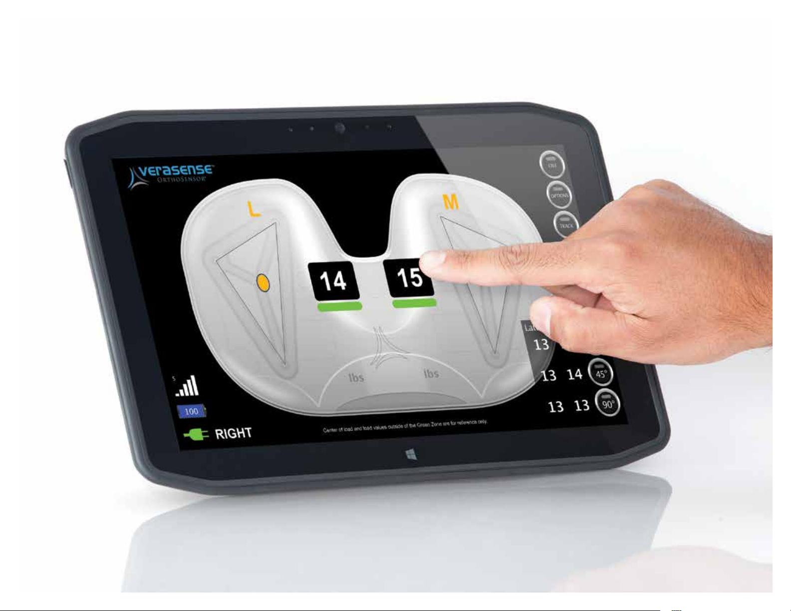
*Center of load and load values outside of the Gree n Zone are for reference only.
VERASENSE OrthoSensor.com
31
12/2018 LB-5092 Rev. 2
Page 32
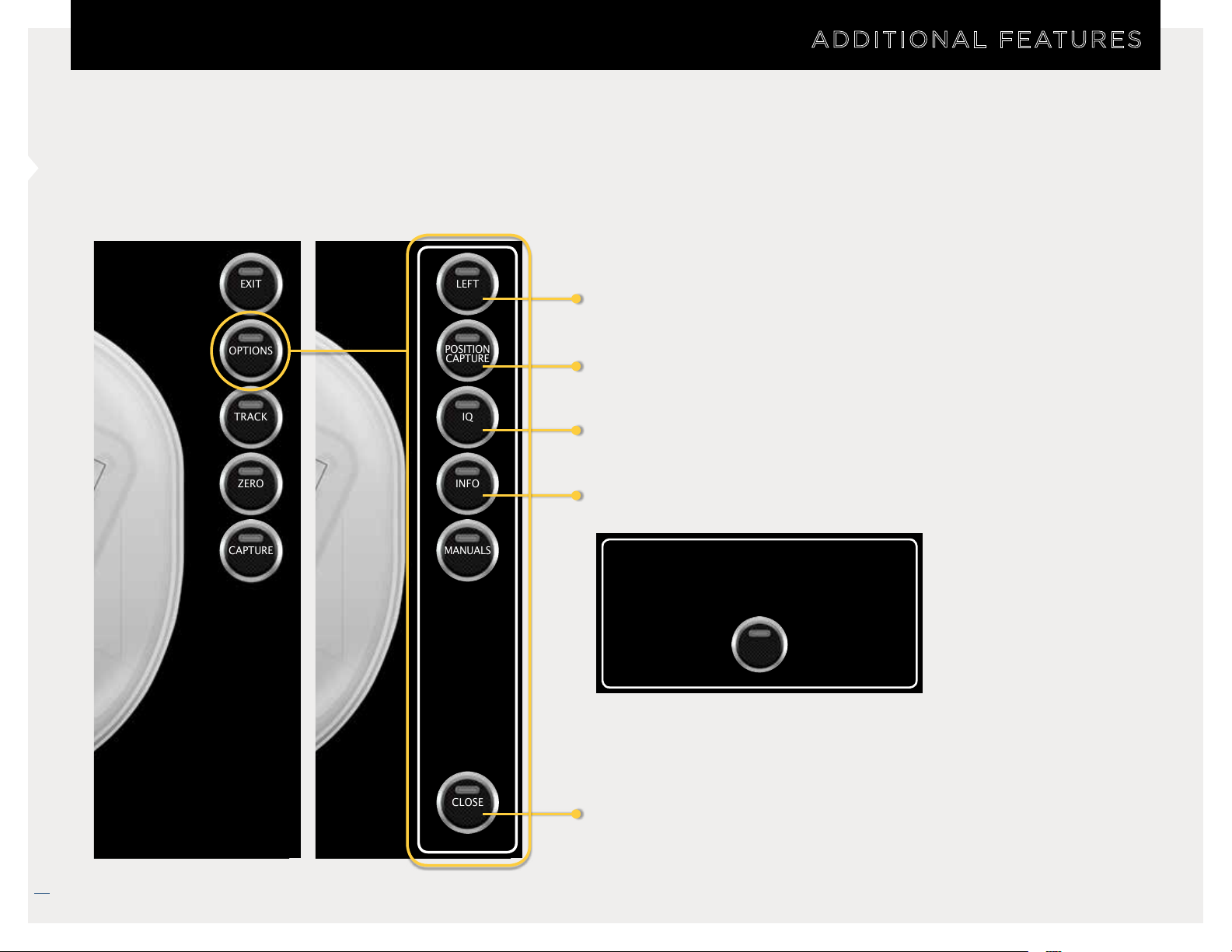
OPTIONS MENU
ADDITIONAL FEATURES
EXIT
OPTIONS
TRACK
ZERO
CAPTURE
LEFT
POSITION
CAPTURE
IQ
INFO
MANUALS
Left/Right Leg Selection
Open/Close the 10/45/90 Position Capture Table
Open OrthoLogIQ* Web Portal
Open VERASENSE Information Panel
Side: Left
Device ID: 512193013
Device Type: OrthoSensor VERASENSE
OK
32
CLOSE
Exit Options Panel
VERASENSE OrthoSensor.com
* Orth oLogIQ is only available to those end-users who purchase it pursuant to a separate agreement with OrthoSenso r, Inc. O rthoLogIQ is only available in the U nited States.
12/2018 LB-5092 Rev. 2
Page 33
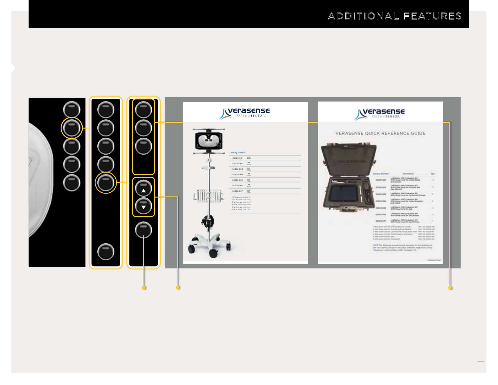
DISPLAY AVAILABLE MANUALS
ADDITIONAL FEATURES
EXIT
OPTIONS
TRACK
ZERO
CAPTURE
LEFT
POSITION
CAPTURE
IQ
INFO
MANUALS
CLOSE
IFU
Quick
Reference
Guide
User
Guide
CLOSE
VERASENSE
QUICK REFERENCE GUIDE
Catalog Number Description Qty
05000-001
05000-002
05000-003
05000-004
05000-005
05000-006
05000-007
1 With power cord for United States and Canada
2 With power cord for Australia and New Zealand
3 With power cord for Continental Europe & South Korea
4 With power cord for United Kingdom and Ireland
5 With power cord for Italy
6 With power cord for Switzerland
NOTE The following accessories are necessary for the operation of the VERASENSE
device: VERASENSE Software Application, Transceiver, and LinkStation MINI.
1
LinkStation MINI
With Power cord for United States and Canada
2
LinkStation MINI
With Power cord for Australia and New Zealand
3
LinkStation MINI
With Power cord for Continental Europe
4
LinkStation MINI
With Power cord for United Kingdom and Ireland
5
LinkStation MINI
With Power cord for Italy
6
LinkStation MINI
With Power cord for Switzerland
3
LinkStation MINI
With Power cord for South Korea
PART NO. 05000-410
PART NO. 05000-555
PART NO. 05000-411
PART NO. 05000-412
PART NO. 05000-413
PART NO. 05000-414
OS-VS-16-0162 Rev. 4
1
1
1
1
1
1
1
Exit to VERASENSE
Active Monitoring
Screen
Page Up /
Page Down
Buttons
Opens & Displays
the appropriate manual
when selected.
VERASENSE OrthoSensor.com
33
12/2018 LB-5092 Rev. 2
Page 34
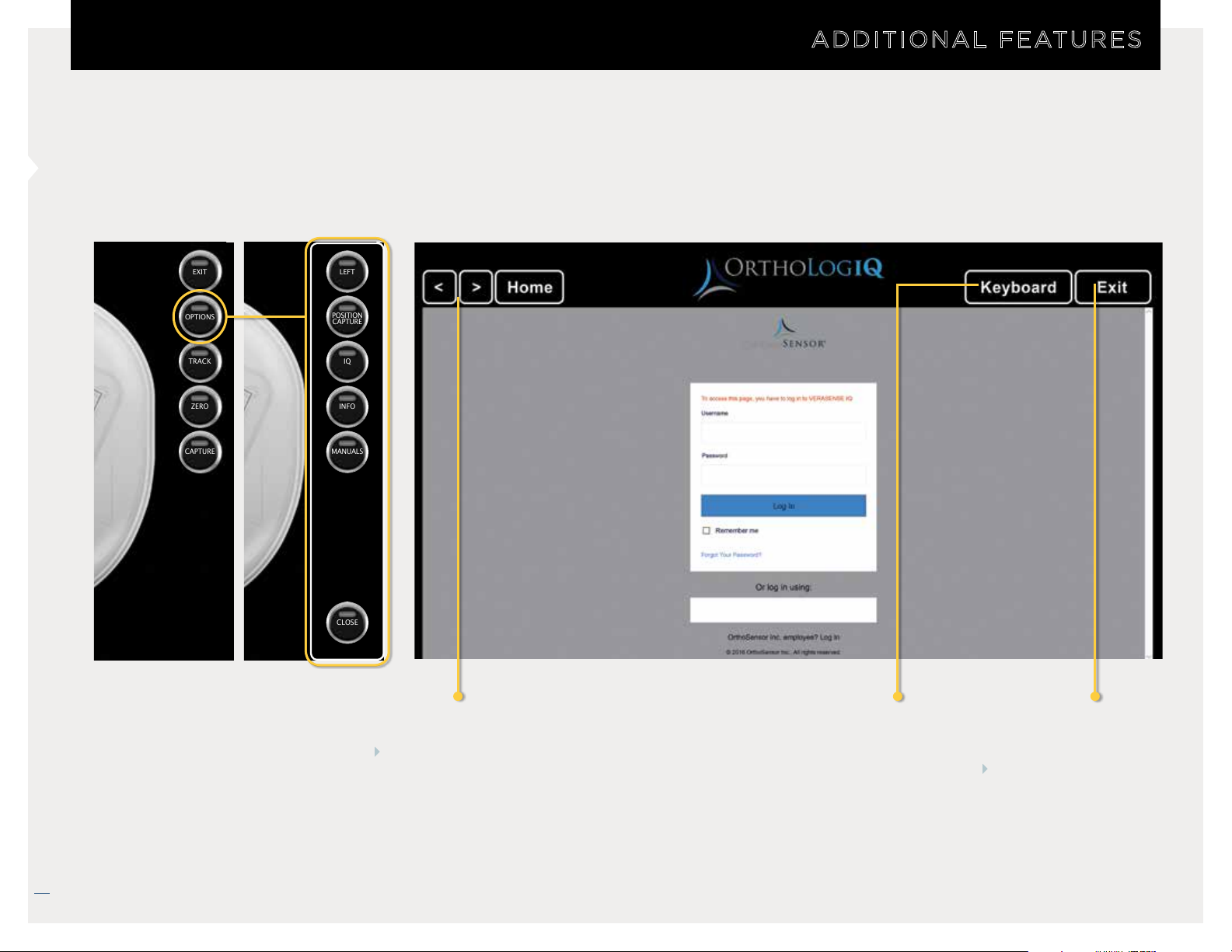
ORTHOLOGIQ MODE (“IQ MODE”)
ADDITIONAL FEATURES
EXIT
OPTIONS
TRACK
ZERO
CAPTURE
LEFT
POSITION
CAPTURE
IQ
INFO
MANUALS
CLOSE
34
Browser Controls
Back/Forward
Home
Open/Close
Digital
Keyboard
Exit to VERASENSE
Software Application
If user exits IQ mode,
browser will minimize
and can be reopened
with IQ button.
VERASENSE OrthoSensor.com
* Orth oLogIQ is only available to those end-users who purchase it pursuant to a separate agreement with OrthoSenso r, Inc. O rthoLogIQ is only available in the U nited States.
12/2018 LB-5092 Rev. 2
Page 35
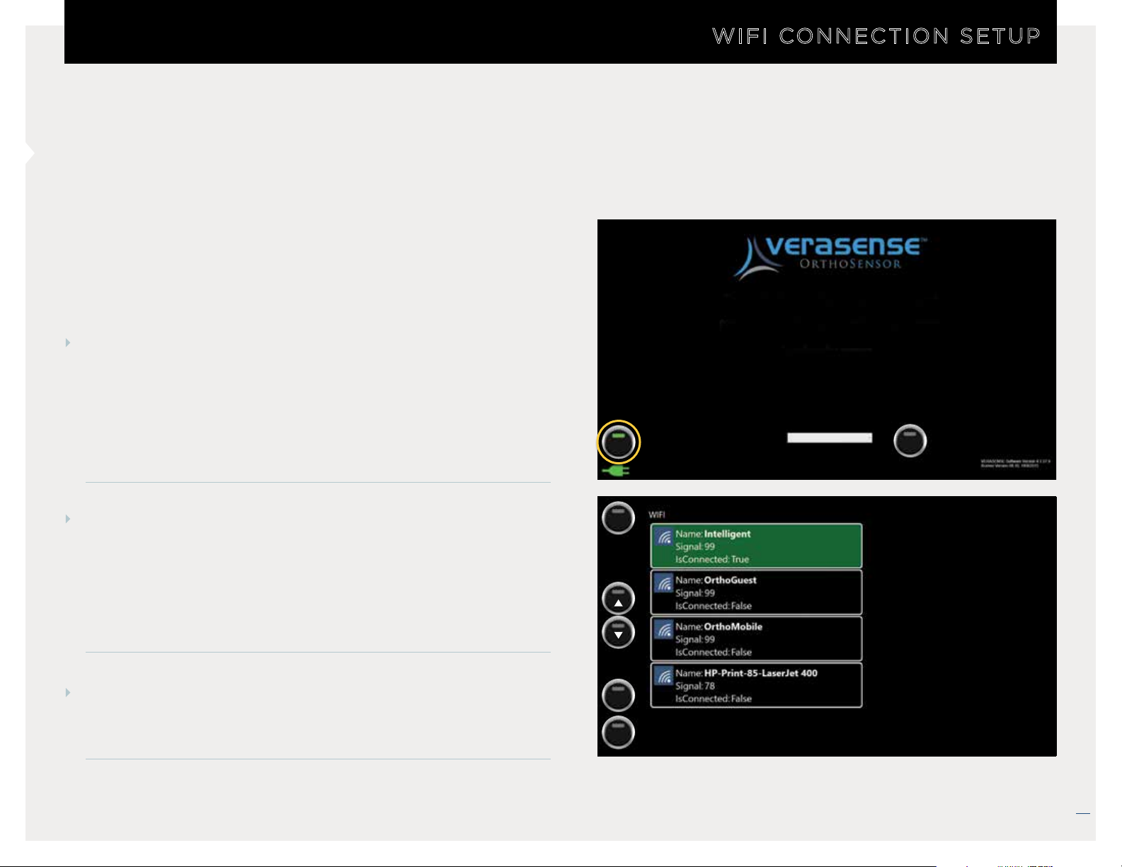
WIFI CONNECTION SETUP
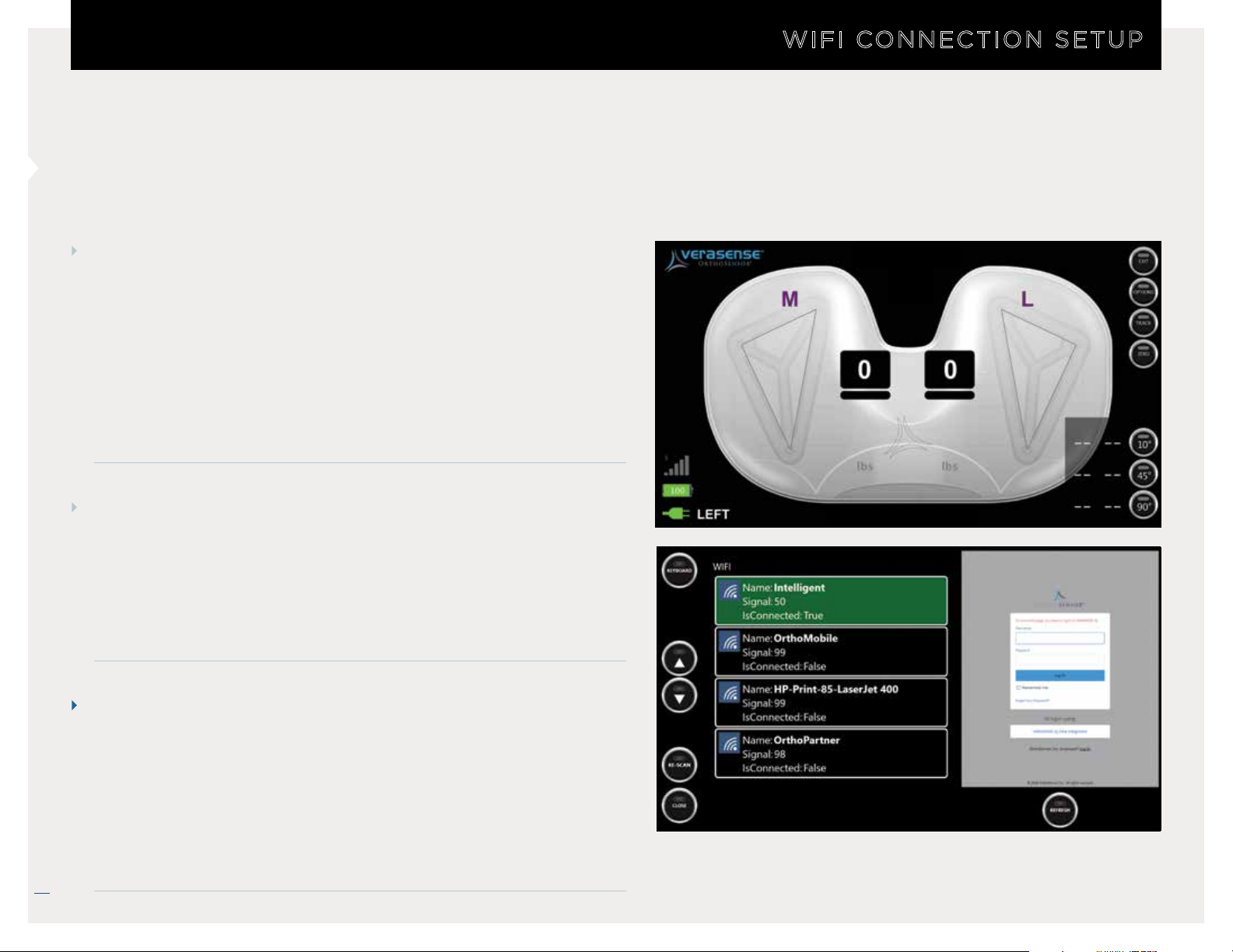
The WIFI Button in the lower left-hand corner will indicate the
connection status of the VERASENSE Software Application:
WIFI CONNECTION SETUP
GREEN = WIFI Connected
RED = WIFI Not Connected
STEP 1
Select the WIFI button to connect the VERASENSE Software
Application to a wireless network or to acknowledge a
network access policy for a connected (green) network.
• On the WIFI Network Configuration Screen, a list will
populate with the names of all available networks.
STEP 2
Use the UP and DOWN arrows to scroll through the list of
available networks.
NOTE: If desired network is not shown, please select the
RE-SCAN button to repopulate the network list.
STEP 3
WIFI
KEYBOARD
RE-SCAN
Please activate sensor by placing it on the magnet
(Keep sensor on the magnet until application starts)
Searching for sensors...
Physician Name
Surgeon Not Listed
POWER
Select the desired WIFI network by touching the appropriate
network box.
CLOSE
VERASENSE OrthoSensor.com
35
12/2018 LB-5092 Rev. 2
Page 36
SELECTING THE OPEN NETWORK
STEP 1
After selecting the appropriate WIFI network, enter the
Network Security Key:
WIFI CONNECTION SETUP
• Press the
• Select the Network Security Key field and enter key.
• Press the
KEYBOARD button to open the virtual keyboard.
CONNECT button.
NOTE: If the WIFI network does not have a Network Security
Key, select the
CONNECT button to proceed.
STEP 2
To confirm a successful WIFI network:
• The connect WIFI network will appear in GREEN.
• Is Connected = True
• On the right portion of the screen, the OrthoLogIQ* login page
will appear.
NOTE
If the the selected network requires acceptance of a local
internet access policy , a pop-up window will appear in the
right-hand side of the WIFI Configuration Screen. Enter the
required policy information.
36
To exit to the Home Screen, select the CLOSE button in the
VERASENSE OrthoSensor.com
bottom left corner.
* Orth oLogIQ is only available to those end-users who purchase it pursuant to a separate
agreement with OrthoSensor, Inc. O rthoLogIQ is only available in the U nited States.
12/2018 LB-5092 Rev. 2
Page 37
KEYBOARD HOT KEYS
STEP 1
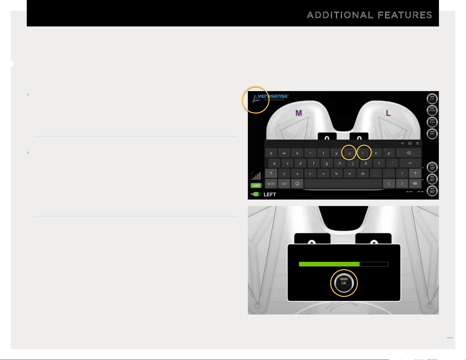
Press the top left corner of the screen to open the digital keyboard.
• Works on both the VERASENSE Software Application
Activation and Active Monitoring screens.
STEP 2
“Hot-keys” have been designated for added features:
U – Initiate the utilization data upload to cloud. Select OK once
•
the upload is complete.
•
I – Open IQ mode. Allows user to access OrthoLogIQ once
VERASENSE has been shutdown.
ADDITIONAL FEATURES
Center of load and load values outside of the Green Zone are for reference only.
Uploading Utilization Data...
* Center of load and load valu es outside of the Green Zone are for reference only.
* Orth oLogIQ is only available to those end-users who purchase it pursuant to a separate agreement with OrthoSenso r, Inc. O rthoLogIQ is only available in the U nited States.
VERASENSE OrthoSensor.com
37
12/2018 LB-5092 Rev. 2
Page 38
NOTES
38
VERASENSE OrthoSensor.com
12/2018 LB-5092 Rev. 2
Page 39
NOTES
39
12/2018 LB-5092 Rev. 2
VERASENSE OrthoSensor.com
Page 40
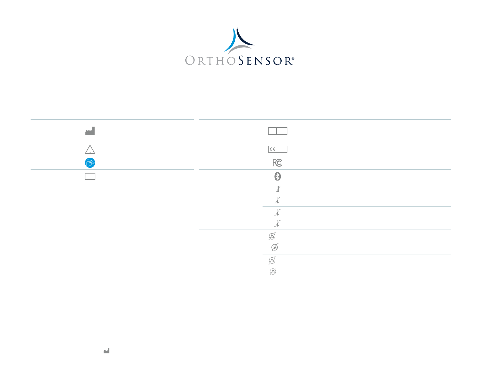
OrthoSensor is the technology leader in the development of intelligent orthopaedic solutions that
60°C
37°C
50°C
0°C
50°C
5%
95%
non-condensing
30%
100%
5%
95%
non-condensing
10%
80%
non-condensing
provide real-time intraoperative data to surgeons and hospitals. OrthoSensor
intelligent orthopaedic
solutions utilize proprietary sensor technologies with the goal of improving healthcare outcomes and
potentially reducing the cost of treating musculoskeletal disease.
MANUFACTURER
CAUTION
DOCUMENTATION
IDENTIFICATION
SN
OrthoSensor, Inc.
1855 Griffin Road, Suite A-310
Dania Beach, FL 33004-2200, USA
Consult User Guide
Serial Number
REPRESENTATIVE IN THE
EUROPEAN COMMUNITY
AUTHORIZED
CE MARK
FCC ID
BLUETOOTH
TEMPERATURE LIMIT
IN OPERATION
IN STORAGE
-10°C
15°C
0°C
Emergo Europe
REPEC
Prinsessegracht 20
2514 The Hague, The Netherlands
0297
LinkStation MINI & LinkStation MINI Eval. Kit
VERASENSE
LinkStation MINI & LinkStation MINI Eval. Kit
VERASENSE
RELATIVE HUMIDITY
IN OPERATION
LinkStation MINI & LinkStation MINI Eval. Kit
submersion
VERASENSE
LinkStation MINI & LinkStation MINI Eval. Kit
IN STORAGE
VERASENSE
Surgeons must always rely on one’s own professional clinical judgment when deciding on whether to use a particular product for patient care. OrthoSensor does not provide medical advice and
recommends that surgeons be trained in the use of any particular product before surgical use. No portion of this should be redistributed, duplicated or disclosed without the express written consent of
OrthoSensor, Inc. Information presented is intended to demonstrate the breadth of OrthoSensor product offerings. Surgeons must always refer to the package insert, product label and/or IFU before
using any OrthoSensor product. OrthoSensor products may not be available in all markets because product availability is subject to the regulator and/or medical practices in individual markets.
For additional product information, including indications, contraindications, warnings, precautions and potential adverse effects, see the Instructions For Use and OrthoSensor website. All trademarks
herein are property of OrthoSensor, Inc. or its subsidiaries unless otherwise indicated. Copyright 2017 OrthoSensor, Inc.
www.OrthoSensor.com | CustomerService@OrthoSensor.com
U.S. Only +1 888.75.ORTHO (+1 888.756.7846) | U.S. and International +1 954.577.7770 | Fax +1 954.337.9222
OrthoSensor, Inc. | 1855 Griffin Road, Suite A-310 | Dania Beach, Florida 33004 USA
12/2018 LB-5092 Rev. 2
 Loading...