

Orthogonal Devices ER-102 User Manual

User Manual
ER-102:
Sequencer Controller
with Firmware v1.04
Last revised on April 4, 2015
OD
Orthogonal Devices © 2015
IntroductIon 3
What does it do? 3
The interface 3
Math transforMs 4
Edit screen 4
Operations 5
Identity 5
Inversion 5
Examples 6
Parts 7
What are parts? 7
Interface 8
Voltage control 9
Various types of parts 10
Transitions 11
GrouPs 12
What are groups? 12
Selecting steps 12
Applying transforms 13
Modiers 14
recordInG 16
Real-time mode 17
Step mode 19
Alter mode 20
rotoInversIon 21
storaGe 22
Snapshots 23
Loading MIDI Files 24
User Voltage Tables 25
The Conguration File 26
Updating the rmware 27
2
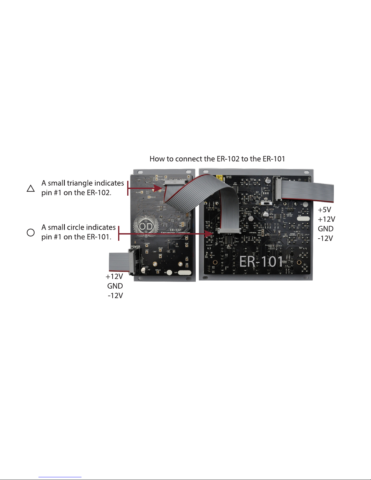
Please update your ER-101 to at least v2.02 of the
rmware before connecting it to the ER-101.
3
What does it do?
The ER-102 Sequencer Controller is an expander for the ER-101. The design and
feature set implemented by the ER-102 is the result of the critical distillation of the
many overlapping feature requests that were made by users during the rst year of
the ER-101’s release.
TIP: Throughout this manual, I will assume that you are already familiar with the ER-
101’s interface. If that is not the case then please rst read the ER-101 User Manual.
The interface
The ER-102 interface is divided into 4 sections:
• STORAGE: a memory card for holding snapshots and loading rmware.
• PARTS: adds up to 99 CV-controllable loops (each with their own reset step) to
each snapshot.
• GROUP: adds up to 16 arbitrary selections of steps each with their own transforms and routing matrix that is connected to a 3 channel modulation bus.
• RECORDING: adds a comprehensive and recongurable set of inputs that can
record new sequences, alter existing ones, or place the ER-101 under remote
editing control.
The ER-102 was designed to be place to the right of the ER-101. This layout was
chosen to minimize the impact on your hand motions when including the ER-102
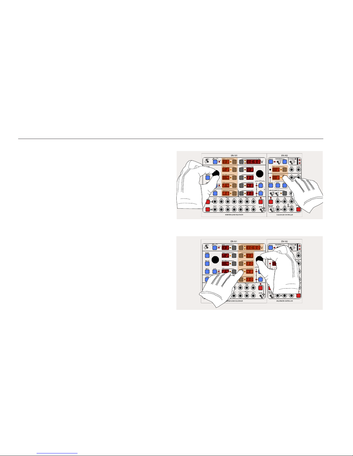
in your workow. For example, the LEFT knob on the ER-101 is used whenever
changing any values on displays with focus buttons on their right (INDEX, TRACK,
PATTERN, STEP, SNAPSHOT, PART and GROUP). The RIGHT knob on the ER-101 is
used whenever changing any values on displays with focus buttons on their left
(VOLTAGE, vCV-A, CV-B, DURATION, and GATE). The result is that your hands never
obstruct the displays that you need to see while you are manipulating the interface.
TIP: Throughout this manual, a “focus press” means to press the focus button of a
display that is already focused. If the display is not focused, then you will need to
focus it rst and then press it again to get the desired eect.
IntroductIon
The possible targets for the LEFT knob are highlighted.
The possible targets for the RIGHT knob are highlighted.
4
Under the ER-101/102 paradigm, whenever you want to operate mathematically on
the parameters of a single step or multiple steps, you use a MATH transform. Examples of such operations are transposing pitch values, randomizing gate lengths, doubling or halving step durations, and quantizing random note durations or pitches to
a xed grid.
There are two types of transforms, destructive and non-destructive. A destructive
transform permanently alters the stored parameters of the target steps. These
destructive transforms are always accessed via the MATH button. A non-destructive
transform alters step parameters as they are being interpreted during playback but
without changing their stored values. You will nd non-destructive transforms in
the GROUP MODIFIER section of the ER-102’s interface.
All transforms share the following interface:
UI Element Function
LEFT knob Selects an operation (i.e. add, multiply, randomize, etc.).
RIGHT knob Changes the focused operator’s parameter.
FOCUS buttons Focuses the interface on a particular step parameter.
DELETE button Clears all operations so that the transform has no eect.
Edit screen
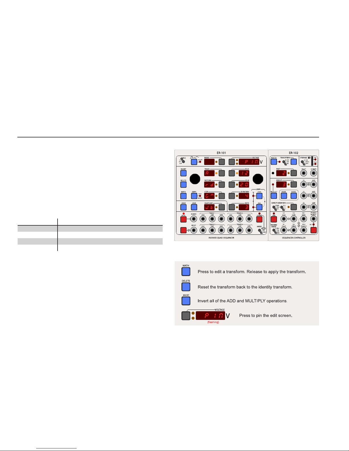
Pressing and holding the MATH button will activate the TRANSFORM EDIT screen for
any of the desctructive transforms associated with tracks and groups.
TIP: When you rst enter the TRANSFORM EDIT screen, the word “PIN” will be ash-
ing in the VOLTAGE display. Press the VOLTAGE focus button to pin the TRANSFORM
EDIT screen so that you do not have to hold the MATH button while making long
edits to the transform. Pressing the MATH button while pinned in the edit screen
will apply the current MATH transform.
The TRANSFORM EDIT screen for the non-destructive group transforms is automatically activated when editing the GROUP MODIFIERS (refer to the chapter on groups).
Math transforMs
The TRANSFORM EDIT screen: Turning the LEFT knob will change the focused
operation for the focused parameter (in this case CV-A). Turning the RIGHT knob will
change the focused operation’s paramter value.
5
Operations
Whenever you apply a transform, all of the operations that it contains are applied
sequentially in the following order to each step parameter:
1. Add RANDOM(Rd)
2. Multiply by G
3. Add JITTER(Jt)
4. Add A
5. Quantize to Qt
The result is the following formula:
P
after
= QUANTIZE(G*(P
before
+ RANDOM(Rd)) + JITTER(Jt) + A,Qt)
where,
P
after
: The new value of the step parameter
P
before
: The old value of the step paramter
QUANTIZE(x,y): Round x to the nearest multiple of y
RANDOM(x): Random integer between 0 and x (uniform distribution)
JITTER(x): Random integer between -x and x (uniform distribution)
If for a particular step and parameter, the transform results in a P
after
that is outside
the valid range of the step parameter then the transform will have no eect on that
parameter. For example, trying to subtracting 50 from CV-A = 12 will have no eect.
TIP: In the case of non-destructive transforms, the Jitter and Random operations are
re-evaluated every time a target step is played.
Identity
A transform with all default values for each of its operations has no eect and is
called the identity transform. You can quickly reset any transform back to its identity
by pressing the DELETE button while in the TRANSFORM EDIT screen.
Inversion
You can invert a transform that you are editing by pressing the INVERT button. Also,
you can apply the inverted version of a transform by holding the INVERT button
while pressing and releasing the MATH button. Transform inversion only applies to
the Add (A) and Multiply (G) operators.
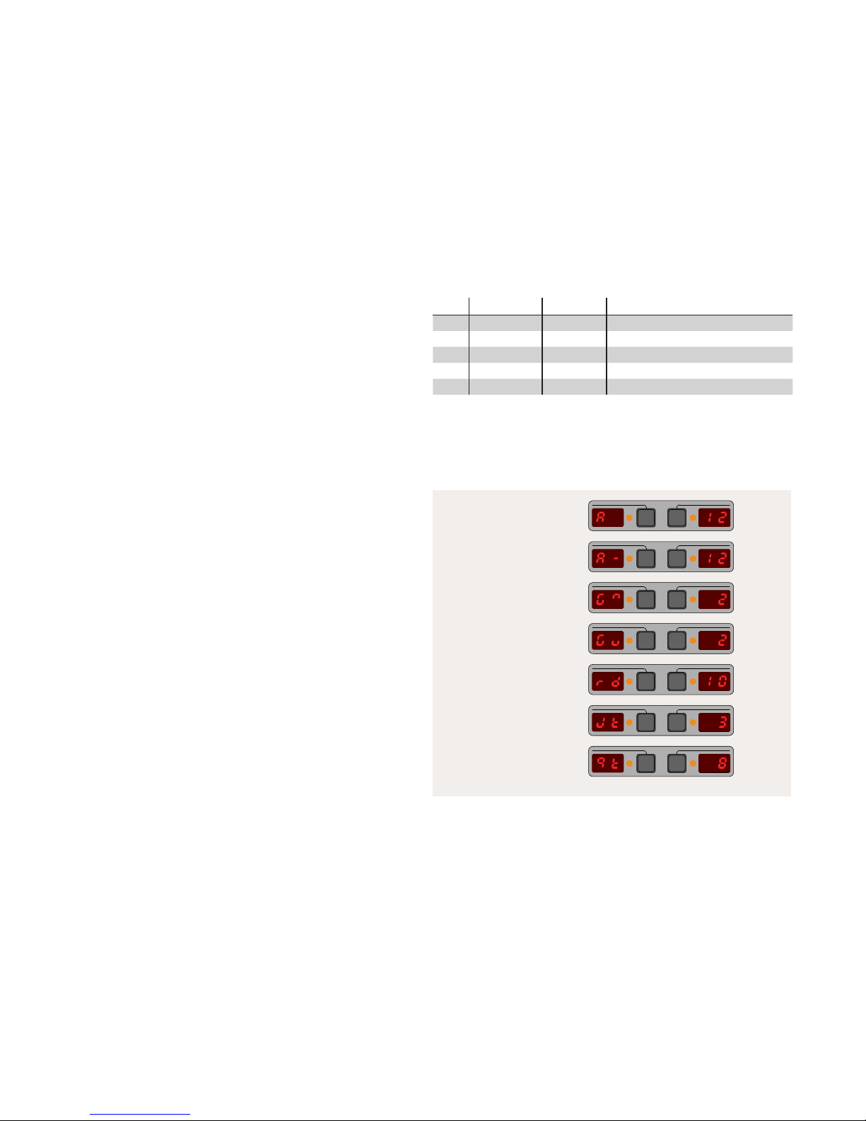
Add 12.
Subtract 12.
Multiply by 2.
Divide by 2.
Add a random number
between 0 and 10.
Add a random number
between -3 and 3.
Round to the nearest
multiple of 8.
Code Operation Range Eect
A Addition -99 to 99 add A
G Multiplication 1/99 to 99 multipy by G
Jt Jitter 0 to 99 add a random integer between [-Jt, Jt]
Rd Random 0 to 99 add a random integer between [0, Rd]
Qt Quantize 1 to 99 round to the nearest multiple of Qt
The letter codes (aka variables) used in the TRANSFORM EDIT screen to represent
each operation.
Congurable Option: You can edit the conguration le to have only a single opera-
tion active at a time instead of all operations.

6
Examples
Set parameters to a specic value:
To achieve the aect of an assignment operation, just set G = 0 and set A to the
desired value. Typically you would do this when you want to simultaneously set a
particular parameter of many steps to a desired value (e.g. set the DURATION of all
steps in a pattern to 16 clock pulses). Additionally, you can use the JITTER(Jt) parameter to add a bit of zero-centered random noise to the parameter. This is especially
useful for velocity CVs and gate lengths.
Generate random parameter values in a given range:
The RANDOM operation produces random integers between 0 and Rd. If you want
random numbers between L and H, then just set A = L and Rd = H-L. For example,
to get random values between 12 and 19, set A = 12 and Rd = 7. This is often done
when producing random pitch values that are within a restricted range.
Generate random pitches separated by a given xed interval:
To generate random multiples of a given number just set Rd and A as you would for
producing random numbers in a range but also set G to the desired interval size. For
example, to produce random pitch values from one octave of the whole tone series
then set G=2, Rd=6, and set A to the root pitch. Alternatively, you can use RANDOM
with the QUANTIZE operation: Rd=12 and Qt=2.
Generate random rhythms with customized probabilities:
Start with a simple sequence of steps with all the GATE parameters set to zero. If
you apply a MATH transform of [GATE+RANDOM(4)]/3 to the entire track then you
will get random sample of steps with a GATE parameter of 1 and the rest will be zero.
Furthermore, if you start with a sequence of steps where some of the steps have a
GATE parameter of 1, 2 or 3 (rather than just zero) then these steps will have a progressively higher probability of being assigned a non-zero GATE after you apply the
MATH transform. This way you can sculpt the resulting random rhythm lightly by
biasing the randomization. For example, this is great for producing random rhythms
that have a higher probability of triggering on the strong beats then on the weak
beats.
This example works especially well with the HIGH/LOW transforms (see Groups)
because the initial probability contour is not overwritten by the application of these
non-destructive transform, and, the HIGH/LOW transforms get re-evaluated everytime a step is played, thus producing a continually evolving rhythm that nevertheless adheres to the user’s specied probability contour.
7
What are parts?
The top section of the ER-102 is dedicated to the manipulation of parts. Using parts,
you can divide tracks into smaller sub-sequences (called parts) and then activate
these parts during playback using the manual interface or using voltage control. A
single snapshot can contain up to 99 parts.
Looping dierent sections of a track on just the ER-101 is a very eective way of
introducing variations in real-time. However, there are some limitations with a
standalone ER-101:
• You cannot save and recall multiple loops.
• You cannot activate dierent loops simultaneously across all or some tracks.
• You cannot change the step that the ER-101 rewinds to on a reset signal.
• There is no external voltage control of the play cursor.
The ER-102 removes each of these limitations by introducing the concept of a part.
A single part assigns a reset step and a looped section for each of the 4 tracks such
that when a part is triggered, potentially all tracks will have their reset steps and
looped sections changed.
Parts

8
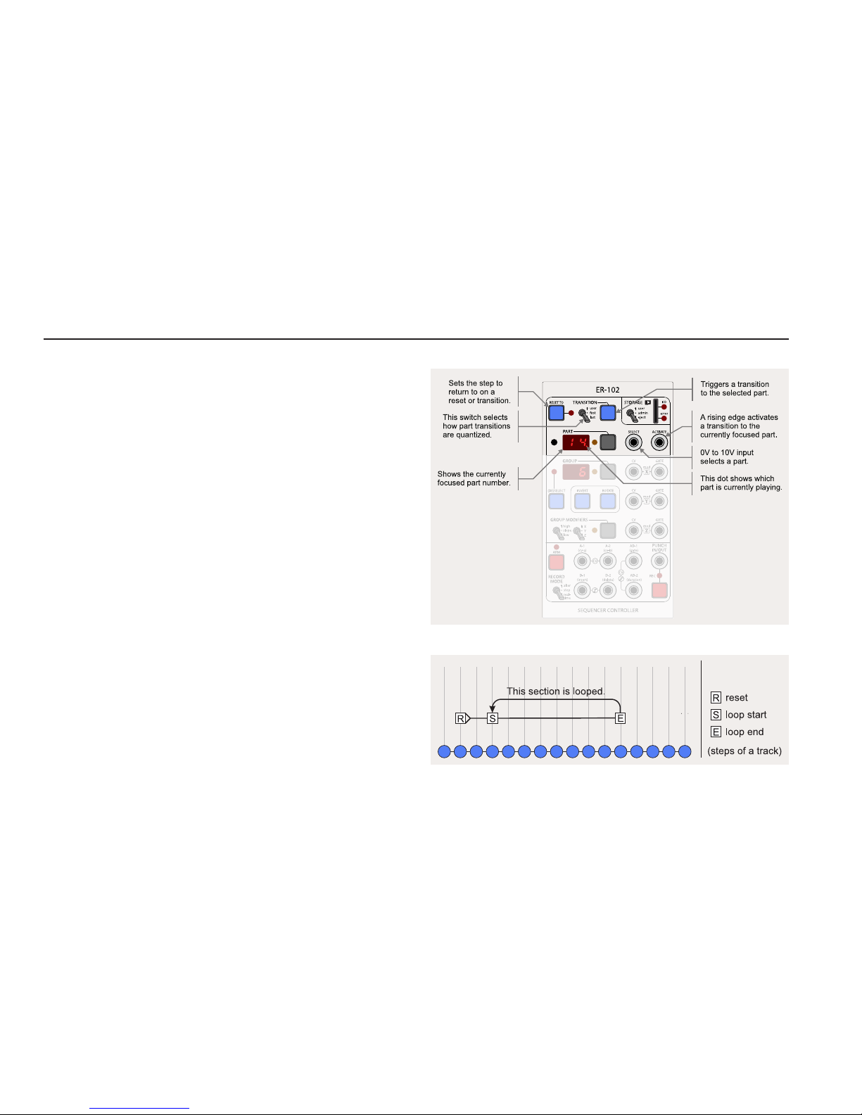
Interface
At any time there will always be a part that is focused and a part that is playing. Sometimes, there will also be part that is pending. When the PART display is
focused, you can change the part by turning the LEFT knob. Also, the INDEX and
VOLTAGE display are commandeered to show information relevant to the focused
part and the next pending part, if any.
Focused Part
The focused part is the part whose number is showing in the PART display. When
you are changing the reset step or the loop section for the current track, then your
changes are always applied to the focused part. The looped section of the focused
part is set with the LOOP START and LOOP END buttons on the ER-101, while the
reset step is assigned with the RESET TO button on the ER-102.
Pending Part
The pending part is the part that is scheduled to play next (i.e. after the current part
nishes). When the PART display is focused then the pending part will be shown in
the INDEX display on the ER-101. Also, the PART display’s orange LED will ash when
a part is pending.
Playing Part
The currently playing part is indicated by the dot in the lower right of the PART
display. All tracks will adhere to the reset step and looped section assigned in the
playing part.
Part Overview (experimental)
When the PART display is focused a rough overview of the focused part is shown
in the VOLTAGE display. The display is divided horizontally into 4 sections, one for
each track. Each section holds 3 horizontal bars that indicate (from top to bottom)
whether the RESET TO, LOOP START, and LOOP END steps have been set in their
respective tracks.
Quick Navigation
If you hold down the PART focus button and turn the LEFT knob then the cursor will
skip in order through the steps in the following list:
First step - RESET TO step - LOOP START step - LOOP END step - Last step
In this example, the PART display is focused and part 6 is showing. The VOLTAGE
display shows an overview of the part and we can see that track 1 has a RESET TO,
LOOP START and LOOP END all set, while track 2 only has the LOOP START and LOOP
STOP set. Track 3 has none of them set and track 4 has RESET TO and LOOP END set.
Additionally, we can see that part 3 is pending to be played after part 6.
9
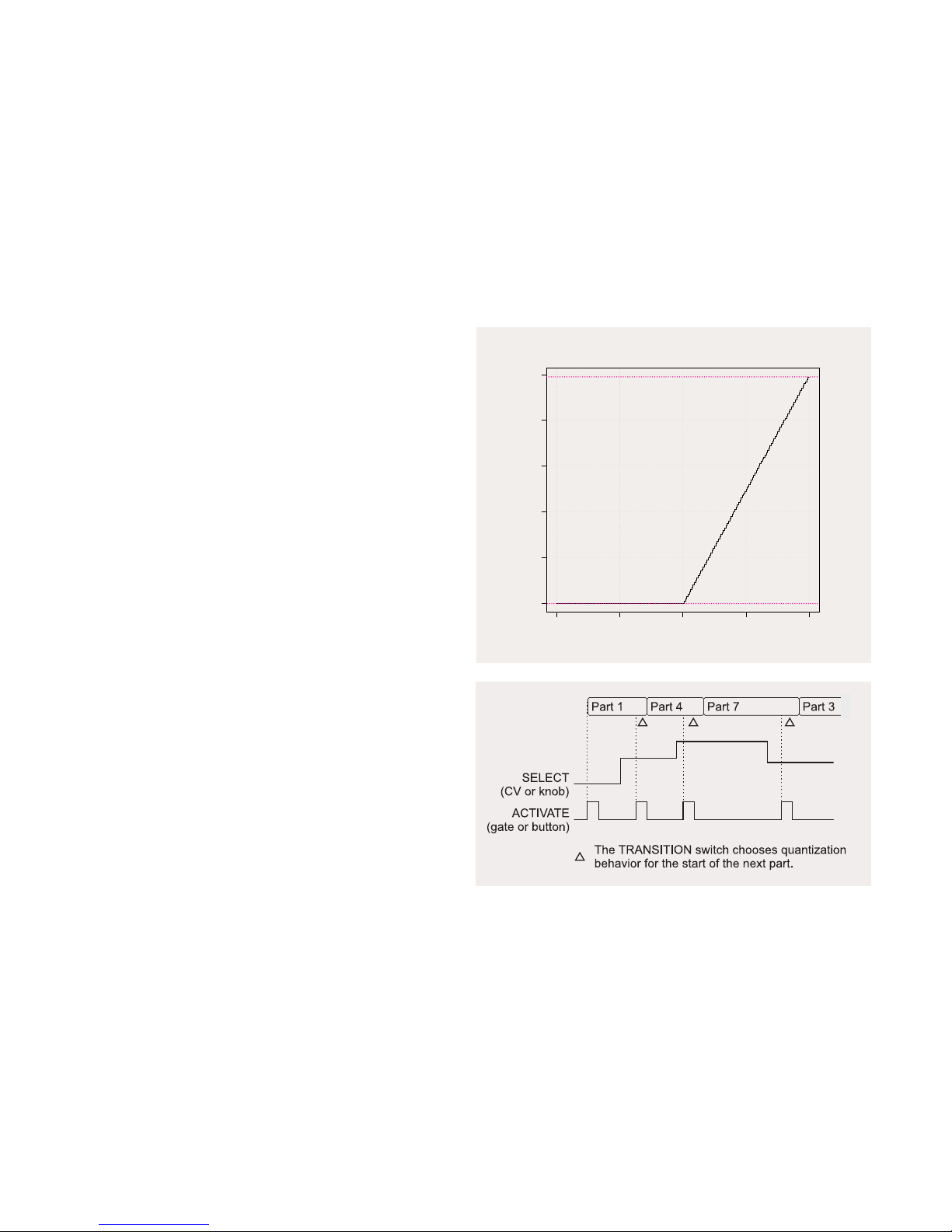
Voltage control
Parts can be focused and activated using external voltage control just by patching
a suitable CV/gate source into the SELECT and ACTIVATE jacks on the ER-102. The
SELECT voltage is converted to a PART number according to the chart on the right.
TIP: As soon as you insert a cable into the SELECT jack, part selection is placed
under external voltage control. This means that the LEFT KNOB can no longer be
used to alter the focused part. If you try to change the focused part with the LEFT
knob while a cable is patched into the SELECT jack, the word “PLUG” will ash in the
VOLTAGE display to remind you that part selection is under external voltage control.
Remove the cable to once again be able to select parts via the LEFT KNOB.
Once a part is selected (or focused), then this part can be activated with gate signal
to the ACTIVATE jack. In fact, as long as the ACTIVATE input is held high the pending
part (or next part cued to play) will track the voltage selection. This allows you to
eectively “play” parts in real-time.
TIP: The actual timing of when the newly activated part starts playing depends on
the position of the TRANSITION switch (see the section on Transitions).
−10 −5 0 5 10
0 20 40 60 80 100
VOLTAGE
PAR T
part = oor(voltage*10)
maximum:99
minimum:0
 Loading...