

Page 1

USER MANUAL
July 2008
Page 2
2
inc
All rights reserved
Please give this manual to the owner of the
wheelchair.
Please read this manual in it entirety before using your
wheelchair for the first time. Read this
manual until it becomes familiar and pay close attention to
the warnings.
If you have any questions about non-covered subjects in this
manual, please consult a technician in an authorized service
center or contact our customer service at: 1-(418)-847-5225
Center:
Address:
Phone:
The adjustments of your wheelchair must be made by
a health care professional. Inadequate adjustments can
cause wounds and/or damage to the user, the caregiver, the
wheelchair or the environment.
Do not install unauthorized accessories. Always consult a
health care professional for any modifications to your
wheelchair.
Page 3

3
inc
All rights reserved
is proud to count you among its customers and thanks you for having
chosen one of its products.
All the products manufactured by
respect or exceed the highest standards
of quality and safety currently in force in the industry.
employees are
guided by the desire to satisfy expectations of his customers. This is why
does not hesitate to offer a most complete warranty, applying to the whole wheelchair
elements and components. However, the warranty does not apply to parts and
components damaged by abuse, carelessness, accident and normal use or installed
and modified by an unauthorized person.
This operating instructions manual has been written to enable you to use your
wheelchair safely. You will find in this document, information
relating to safety, operating instructions and adjustments.
In order to optimize the performance of your
and to extend its
lifespan, it is essential to have it check regularly by a technician from an authorized
service center.
refuse any responsibility for physical injuries or damages resulting from an
improper use of its products, from a lack of precaution in their use or from a modification
made without it written assent.
Page 4

TABLE OF CONTENTS
4
inc
All rights reserved
1
SAFETY REQUIREMENTS .......................................................................6
1.1 SAFETY REQUIREMENTS ........................................................ ... ..... ... .. ...... .. ... ..... ... ... ....6
1.1.1 BEFORE TAKING THE ROAD ............................................................................ ... .... .... .... .... .... ... ..6
1.1.2 MOVING WITH THE WHEELCHAIR............................................................... ................................7
1.1.3 TO CARRY OUT TRANSFERT.......................................................................................................7
1.1.4 VARIOUS HANDLING OPERATIONS.............................................................................................8
1.1.5 CLEANING AND MAINTENANCE OF COMPONENTS..................................................................9
1.2 WHAT ABOUT THE ELECTROMAGNETIC ENERGY......................................... ............ 9
1.2.1 CAUTION.......................................................................................................................................10
1.2.2 USING TRANSMITTERS AND RECEIVERS................................................................................10
2
RECOMMENDED USE............................................................................11
3
SPECIFICATIONS...................................................................................12
4
SETUP INSTRUCTIONS..........................................................................14
4.1 FOOTREST..................................................................................................................... ..14
4.1.1 TO ADJUST THE FOOTREST LENGHT.......................................................................................14
4.1.2 TO CHANGE THE ANGLE OF THE FOOTPLATE .......................................................................15
4.1.3 TO CHANGE THE DEPTH POSITION OF THE COMPOSITE FOOTPLATE ..............................15
4.1.4 TO CHANGE THE ANGLE OF THE FULL LENGTH FOOTPLATE..............................................16
4.1.5 DEPTH ADJUSTMENT OF THE HEEL LOOPS............................................................................16
4.1.6 ADJUSTMENT OF THE TOE LOOPS..................................................... ........ .... .... ... .... .... .... ... ....16
4.1.7 TO CHANGE THE HEIGHT OF THE CALF PAD..........................................................................17
4.1.8 TO CHANGE THE POSITION OF THE CALF PAD ......................................................................17
4.2 ARMREST ........................... ................................... .................................. ........................18
4.2.1 HEIGHT ADJUSTMENT, REMOVABLE, SWINGAWAY ARMREST............................................18
4.2.2 RIGID SIDEGUARD.......................................................................................................................18
4.2.3 REMOVABLE “U” SHAPE SWINGAWAY ARMREST...................................................................20
4.3 ADJUSTABLE BACKREST ANGLE............ . . . . . . . ........... . . ........... . . . . . ........... . . . . . ........... ....21
4.3.1 TO CHANGE THE BACKREST ANGLE........................................................................................21
4.3.2 TO CHANGE THE BACKREST HEIGHT ......................................................................................23
4.3.3 PUSH HANDLES INSTALLATION ................................................................................................24
4.4 DYNAMIC BACKREST....................................................................................................26
4.4.1 DYNAMIC BACKREST INSTALLATION .......................................................................................26
4.4.2 DYNAMIC BACKREST ADJUSTMENT.........................................................................................28
4.5 SEAT............................... .................................. ................................... ........................... ..29
4.5.1 SLING SEAT..................................................................................................................................29
4.5.2 RIGID SEAT...................................................................................................................................30
4.6 ADJUSTABLE ISCHIATIC PROFILE SEAT CUSHION.................................................31
4.6.1 ADJUSTABLE ISCHIATIC PROFILE SEAT CUSHION INSTALLATION......................................32
4.6.2 ISCHIATIC SEAT CUSHION ADJUSTMENT................................................................................35
4.7 FRONT CASTERS ................... ................................ ................................ ........................36
4.7.1 TO CHANGE THE MODEL OR THE HEIGHT OF THE FRONT CASTER...................................36
4.7.2 FORKS PERPENDICULAR ADJUSTMENT..................................................................................37
4.8 REAR WHEELS ....................................................... ................................ ........................38
4.8.1 TO CHANGE THE MODEL OF REAR WHEELS..........................................................................38
4.8.2 CENTER OF GRAVITY ADJUSTMENT.............................................................. .... ... ........ .... ... ....40
4.8.3 REAR HEIGHT ADJUSTMENT.....................................................................................................41
4.9 PARKING BRAKES.........................................................................................................42
4.9.1 TO ADJUST THE POSITION OF THE PARKING BRAKE (Pushing or pulling brake type)..........42
4.9.2 TO CHANGE THE BRAKE LEVERS.............................................................................................43
4.9.3 TO CHANGE THE ANGLE OF THE BRAKE LEVER (pushing brake type only)..........................45
4.10 ANTI-TIPPERS....................................... .................................. ................................... ..... 46
4.10.1 HEIGHT ADJUSTMENT POSITION..............................................................................................46
4.11 ANCHOR POINTS............................................ ................................................................47
Page 5

TABLE OF CONTENTS
5
inc
All rights reserved
4.12 6 WHEELS CONFIGURATION................................ ... ..... ... ... ..... ... ..... ... .. ...... .. ... ..... ... ... ..48
4.12.1 6 WHEELS CONFIGURATION INSTALLATION...........................................................................48
4.13 OXYGEN CYLINDER SUPPORT ....................................................................................51
4.13.1 OXYGEN CYLINDER SUPPORT INSTALLATION.......................................................................51
5
OPERATING INSTRUCTIONS................................................................52
5.1 HOW TO FOLD AND UNFOLD YOUR PRIMA WHEELCHAIR........................ .............52
5.1.1 TO UNFOLD THE WHEELCHAIR.................................................................................................52
5.1.2 TO FOLD THE WHEELCHAIR......................................................................................................53
5.2 BACKREST PUSH HANDLE AND HEADREST ANCHOR ...... . ........... . . . . . ........... . . . . . ....53
5.2.1 BACKREST PUSH HANDLE.........................................................................................................53
5.2.2 BACKREST PUSH HANDLE WITH HEADREST ANCHOR.........................................................53
5.3 SWINGAWAY, REMOVABLE ARMRESTS....................................................................54
5.3.1 TO SWINGAWAY THE ARMREST ...............................................................................................54
5.3.2 REMOVE AND/OR REPLACE THE ARMREST.......................................... .... .... .... ... .... ........ ... ....54
5.4 FLIP-UP, REMOVABLE ARMRESTS................................................ ... .. ...... .. ... ..... ... .....55
5.4.1 TO SWINGAWAY ..........................................................................................................................55
5.4.2 TO REMOVE AND/OR INSTALL...................................................................................................56
5.4.3 HEIGHT ADJUSTMENT ................................................................................................................56
5.5 FOOTRESTS.................................................................................................................. ..57
5.5.1 TO SWINGAWAY ..........................................................................................................................57
5.5.2 TO REMOVE AND/OR INSTALL THE FOOTREST......................................................................59
5.5.3 TO RAISE AND LOWER THE LEGREST .....................................................................................59
5.6 TENSION ADJUSTABLE BACKREST...... ...................................... ................... ............60
5.7 REAR WHEELS ....................................................... ................................ ........................61
5.7.1 TO INSTALL AND/OR TO REMOVE.............................................................................................61
5.7.2 PNEUMATIC TIRE PRESSURE................................................... .... ....... .... .... .... .... ... .... .... .... ... ....61
5.8 PARKING BRAKES.........................................................................................................62
5.8.1 TO APPLY AND DISENGAGE THE PARKING BRAKE the PUSHING type................................62
5.8.2 RETRACTABLE HANDLES................................................... ........................................................62
5.8.3 APPLY – DISENGAGE THE HILL HOLDER.................................................................................63
5.9 ANTI-TIPPERS....................................... .................................. ................................... ..... 64
5.9.1 TO REMOVE AND/OR RETRACT ................................................................................................64
5.9.2 TO RETRACT................................................................................................................................64
5.9.3 TO REPLACE ................................................................................................................................65
5.10 CANE AND CRUTCH HOLDER......................................... .............................................65
5.11 SEAT BELT.............................................................................. ........................................66
5.12 TRANSPORTATION ........................... ................................... .................................. ........67
5.12.1 ANCHOR POINTS LOCALIZATION.......................................................................................... ....67
5.12.2 ADVICE FOR TRANSPORTATION...............................................................................................68
6
MAINTENANCE.. ........................................ ........................................ .....69
7
BREAKDOWN SERVICE GUIDE............................................................71
8
WARRANTY............................................................................................72
9
AUTHORIZED SERVICE CENTRES.......................................................74
Page 6

1
SAFETY REQUIREMENTS
6
inc
All rights reserved
1 SAFETY REQUIREMENTS
1.1 SAFETY REQUIREMENTS
(Applies to all
wheelchairs)
The adjustments of your wheelchair must be made by
a health care professional or a technician in an authorized
service center.
1.1.1 BEFORE TAKING THE ROAD
• Always put the key switch OFF before getting on or off your vehicle.
• Make sure that the batteries are sufficiently charged (see battery status
indicator).
• Make sure that the anti-tippers are installed.
• Make sure that brakes immobilize your wheelchair completely.
• Make sure that the tire pressure is appropriate.
• Make sure that nothing interferes with wheels (scarf, umbrella, etc…).
• Make sure that your seating position is stable.
• Position the backrest in the raised position.
• Make sure the 45° tilt mechanism is in driving position (seat horizontal with the
ground).
• Fasten your seat belt correctly and without too much slack.
• Make sure that swing away legrests are locked in position and that your feet are
stable on them.
• Push down the elevator legrests.
• Make sure that the swing away or removable armrests are locked in their
positions.
• Make sure that the position of the joystick box enable you to carry out all your
movements comfortably and easily.
• Make sure that the joystick rubber cover is in good condition, if not, try to have it
fixed as soon as possible.
• Make sure that your personal effects do not block in anyway the wheelchair
functions.
• Do not install or transport heavy objects on the backrest of your wheelchair
(backpack, bags, grocery, etc).
Page 7

1
SAFETY REQUIREMENTS
7
inc
All rights reserved
1.1.2 MOVING WITH THE WHEELCHAIR
• Avoid any shock to the joystick box or the joystick itself.
• Avoid slippery surfaces (snow, ice, etc).
• Do not change direction abruptly at high speed.
• Do not use your wheelchair on expressways or streets with intense car circulation.
• Do not transport passengers.
• Do not use your wheelchair under extreme climatic conditions (storm, rain, etc).
• If you drive outside at night, ensure that you will be seen by others.
• Do not approach a slope in a diagonal trajectory, always approach the slope in a
straight line, perpendicularly to the slope.
• Do not go down in a slope in reverse.
• Always actuate the lever gently when you start moving in a slope in order to avoid
tipping the wheelchair.
• Do not make a half-turn in a slope.
• Reduce your speed in restricted or encumbered areas.
• Reduce your speed in a crowd and use your horn to announce your presence.
• In front of an obstacle you must stop and cross it perpendicularly and gradually.
• Avoid thresholds of more than 1 ½ in (38 mm), they can endanger your stability.
• Use the elevators to move you from one level to another.
• Do not approach a slope surface exceeding 10° (17% slope).
• Always fasten your seat belt.
• Keep legs on the legrest while driving.
1.1.3 TO CARRY OUT TRANSFERT
• Always put the on/off switch of the joystick box on the OFF position before carrying
out a transfer.
• Never lean forward or backward to reach an object.
• Always place yourself sideway and the near es t you can to the object to reach.
• Use the transfer supports on the armrests to raise yourself, after you made sure that
they are correctly in position.
• If your backrest is inclined, do not sit down on the backrest, you could damage the
backrest and tip the wheelchair.
• Do not raise yourself upright on the footplates, you could damage and/or tip the
wheelchair.
• Do not sit on the armrests. The wheelchair could tip over.
Page 8

1
SAFETY REQUIREMENTS
8
inc
All rights reserved
1.1.4 VARIOUS HANDLING OPERATIONS
Never try to recharge the batteries in your bedroom while you
sleep. During recharge, batteries can produce a harmful gas
who can cause you health problem.
• Do not immerse your wheelchair, it could cause a dangerous electrical problem.
• Do not store or leave your wheelchair without someone taking care of it.
• Do not leave your wheelchair under the rain.
• Do not store your wheelchair in a wet or very cold place, this could cause a
dangerous problem on your motorized wheelchair.
•
does not limit nor exclude that the user remains seated in his
wheelchair when using a road vehicle adapted for transportation (paratransit),
provided the driver and the owner of the aforesaid road vehicle respects, on this
subject, all legislative requirements, rules, laws, protocols, directives, norms,
standards, instructions and recommendations pertaining to such use by
competent authorities.
• Do not travel on tilted surfaces when the wheelchair is in free wheel. If you have
to do it, the caregiver must always be oriented in the direction of the bottom of
the slope.
• Do not raise the wheelchair by its detachable components (armrest, seat, etc).
• Do not use your battery charger in a hermetic place (backpack, drawer, etc.).
• Always put the on/off switch of the charger on the OFF position before
disconnecting the charging connector on the wheelchair.
• Never try to modify the connector (110 V AC) of the battery charger.
• Never try to modify the battery charger connector (24 V DC) which connect to the
wheelchair.
• Never try to recharge the batteries in your bedroom while you sleep.
• Never connect an electric component other than those manufactured by
.
• Never modify the electric circuit of the wheelchair.
• Always protect the joystick box when you have to carry the wheelchair.
• Always immediately replace any damaged electric wires.
• Always carry out regularly maintenance of your motorized wheelchair as
recommended by
.
Page 9

1
SAFETY REQUIREMENTS
9
inc
All rights reserved
1.1.5 CLEANING AND MAINTENANCE OF COMPONENTS
• Clean as soon as possible your joystick box once it been soiled.
• Use a soft rag and a diluted soft soap.
• Do not use detergent based on alcohol or thinner.
• Regularly carry out maintenance of your wheelchair as recommended by
.
1.2 WHAT ABOUT THE ELECTROMAGNETIC ENERGY
All electronic instruments which transmit remote informations are generally
apparatus which emit in the environment some radio waves. These radio waves
are called " electromagnetic energy ".
The functionality of an electronic instrument can be deteriorated by this
electromagnetic energy field. It is what we call " an electromagnetic
interference". Stronger the intensity of energy is, greater the risk of bad
functional problem of the apparatus increase. This energy is measured in volt
per meter (V/m).
All motorized wheelchair are suitable to be affected by these interferences.
However, current technology makes it possible to immunize them against these
risks. It is what is called their electromagnetic level of immunity to the
interference, measured also in volt per meter (V/m).
20 V/m is a level of immunity which offer a good protection against the
electromagnetic interferences. The electronic parts of the R-NET electronic from
do meet standard directive IEC 1000-4-3.
To avoid electromagnetic interferences, it is important to read
and respect the following warning section, before to use your
wheelchair for the first time.
Page 10

1
SAFETY REQUIREMENTS
10
inc
All rights reserved
1.2.1 CAUTION
Waves emitted by :
• Radio and television stations;
• Amateur radio;
• Radio transmitters and receivers;
• Cellular phones;
• Computers laptop.
CAN AFFECT THE CORRECT FUNCTIONALITY OF MOTORIZED WHEELCHAIR.
1.2.2 USING TRANSMITTERS AND RECEIVERS
• Avoid proximity of these sources of electromagnetic emissions.
• Always put the joystick box in the OFF POSITION before using a cellular phone
or a CB apparatus.
• The addition of electric accessories and/or electric modifications made to the
wheelchair will modify its level of immunity to the electromagnetic emissions.
• Always put the key in the OFF POSITION as soon as it safe to do it and that
appears an erratic operation with the wheelchair.
• Please forward any incident of this kind to
.
Page 11

2 RECOMMENDED USE
11
inc
All rights reserved
2 RECOMMENDED USE
The
manual collapsible wheelchair offers all the mechanical
characteristics and necessary functions in order to ensure powerful propulsion with the
least effort possible.
Its structural concept and its frame entirely composed of light and resistant aluminum
alloy offer all the necessary mechanical functions for the adjustment of multiple
components.
Page 12

3 SPECIFICATIONS
12
inc
All rights reserved
3 SPECIFICATIONS
Dimensions
Front casters
Weight: 9.4 kg - 20 pounds (without wheels and footrests)
Pneumatic of 6 x 1 ¼, 7 x 1 ¾, 8 x 1 ¼, 8 x 2 inches
Overall width : Width + 8 ¼ inches
Foam filled insert
Minimum folded width : 12 ½ inches
Semi-pneumatic of 5 x 1 ½”, 6 x 1 ½”, 8 x 1 ½” inches
Overall length : 22 inches without anti-tippers and footrests
High density tires 5 x 1, 6 x 1, 7 x 1 and 8 x 1 inch
(rear wheels 20 inches) Narrow fork at 3 posit ions
Capacity : 250 pounds
Large fork at 3 positions
Frame
Lower fork at 4 positions
Aluminum structure Suspension fork
Epoxy paint – 4 choices of color
Rear wheel
Central propulsion Pneumatic of 20-22-24-26 inches
Seating
Polyurethane of 22-24 inches
Single cross width frame : 14-15-16-17-18 inches Semi-pneumatic of 20-22-24 inches
Double cross width frame : 16-17-18-19-20-21-22-23 inches
Foam filled insert of 20-22-24-26 inches
Depth : 14-15-16-17-18-19-20 inches Spoke wheel of 20-22-24 inches
Removable rigid seat embedded of (0,-1 or -2 inches) Mag wheels of 20-22-24 inches
Profiled or straight cushion 2 or 3 inches Reinforced spoke wheel of 20-22-24-26 inches
Front seat to floor height adjustable from 14 to 21 ½ inches
Hand rims
Rear seat to floor height adjustable from 13 3/8 to 20 ½ inches Aluminum 20-22-24-26 inches
Adjustable Ischiatic seat Plastic coated 20-22-24-26 inches
Backrest
Foam coated 20-22-24-26 inches
Aluminum tubing structure of 1 inch diameter
Wheel locks
Telescopic backrest post angle of 0° or 8° at 8 inches
Standard wheel lock by (pushing or pulling)
Backrest height 13 to 22 inches Angle adjustable lever
Removable rigid plate
Wheel lock extension
Nylon sling backrest Hill holder
Adjustable tension sling backrest
Wheel axle
Adjustable angles -5°, 0°, 5°, 10°, 15°, 20°
Standard
Push bar (rigid and collapsible) Quick release
Dynamic backrest
Footplates
Armrest
Foldable
Swingaway and removabl e Composite
Height adjustable from 7 to 14 inches Aluminum narrow or large
Armrest pad length from 10 to 14 inch, straight or profiled Aluminum narrow or large, angle adjustable
Telescopic clothes guard Aluminum full width
Clothes guard rigid or supple Heel loops
Width of armrest pad straight 2 inches Toe loops
Width of armrest pad profiled 3 inches Front roller bumper
Deported + 3 inches H strap
Footrest
Accessories
Swingaway - Removable
Adjustable headres t
Angle 60° / 70° or 90° parallel or tapered
Restraint belt (car, airplane and velcro) type
Length adjustment of 14 to 19 inches Paratransit anchor points
Length modification less than 14 inches or more than 19 inches Anti-tippers retracted or adjustable in height
Elevating
Cane and crutch holder
Articulated
Oxygen tank support
Calf pad flat or profiled Auxiliary motorized propulsion system
Page 13
3 SPECIFICATIONS
13
inc
All rights reserved
Rear seat to floor height table
PRIMA 4 wheels and 6 wheels
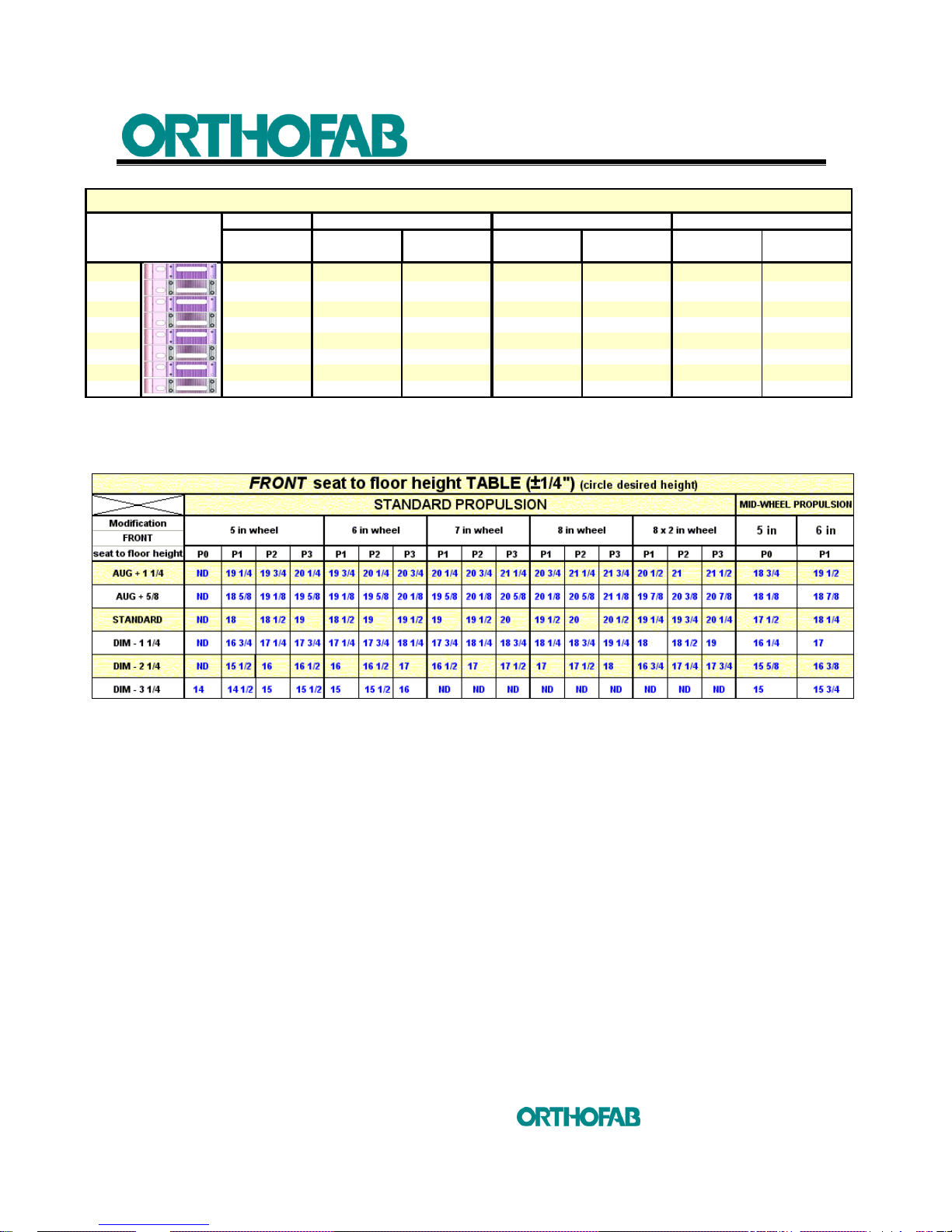
Front seat to floor height table
20" Wheel
1
13 3/8 14 3/8 13 3/4 15 1/4 14 5/8 16 1/8 15 1/2
2
14 15
14 3/8
15 7/8
15 1/4
16 3/4 16 1/8
3
14 5/8 15 5/8 15 16 1/2 15 7/8 17 3/8 16 3/4
4
15 1/4 16 1/4 15 5/8 17 1/8 16 1/2 18 17 3/8
5
15 7/8 16 7/8 16 1/4 17 3/4 17 1/8 18 5/8 18
6
16 1/2 17 1/2 16 7/8 18 3/8 17 3/4 19 1/4 18 5/8
7
17 1/8 18 1/8 17 1/2 19 18 3/8 19 7/8 19 1/4
8
17 3/4 18 3/4 18 1/8 19 5/8 19 20 1/2 19 7/8
Rear seat to floor height
15
Rear seat to floor
22" Wheel 24" Wheel 26" Wheel
Pneumatic
Pneumatic and
Semi pneumatic
Pneumatic and
Semi pneumatic
Polyurethane and
Hight pressure
Pneumatic and
Semi pneumatic
Polyurethane and
Hight pressure
High pressure
Page 14
4 SETUP INSTRUCTIONS
14
inc
All rights reserved
4 SETUP INSTRUCTIONS
After having carried out an adjustment and before using the
wheelchair, make sure that all hardware is tight. Make sure
that all functions are secure before using the wheelchair.
The adjustments of your wheelchair must be made by
a health care professional. Inadequate adjustments can
cause wounds and/or damage to the user, the caregiver, the
wheelchair or the environment.
4.1 FOOTREST
4.1.1 TO ADJUST THE FOOTREST LENGHT
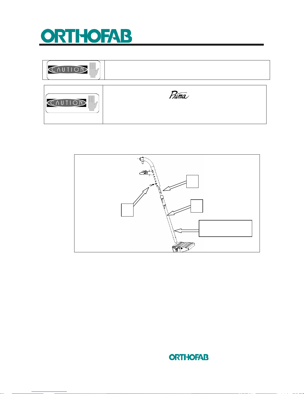
Figure 1 : To adjust the footrest lenght.
To adjust the length of all types of footrest:
1. Remove the adjustment screw (A) using a 7/16" wrench;
2. Adjust the telescopic tubing (C) at the needed length;
3. Put back the (A) screw and tighten firmly.
B
C
A
TELESCOPIC
TUBING
Page 15
4 SETUP INSTRUCTIONS
15
inc
All rights reserved
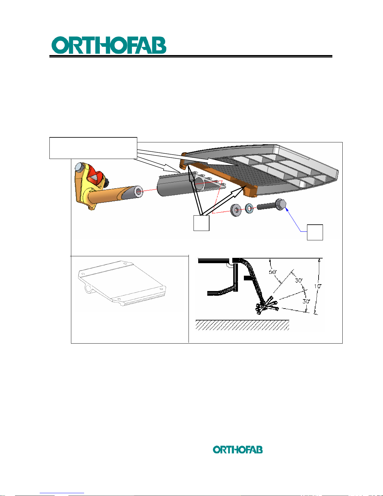
4.1.2 TO CHANGE THE ANGLE OF THE FOOTPLATE
1. Loosen screw (B) using a 10 mm key:
2. Install the footplate at the desired angle;
3. Tighten screw (B) firmly (tightening at 140 Pounds/inch).
Figure 2 : To change the angle of the footplate.
4.1.3 TO CHANGE THE DEPTH POSITION OF THE COMPOSITE FOOTPLATE
1. Remove the two (2) Phillips screws (A) at the end of the footplate (see; figure 2) ;
2. Pull the footplate to release it from the support ;
3. Readjust the footplate at the needed depth ;
4. Replace the end part of the footplate with the Phillips screws (A).
Aluminum footplate
B
COMPOSITE FOOTPLATE
INSERTION GROOVE
A
Page 16
4 SETUP INSTRUCTIONS
16
inc
All rights reserved
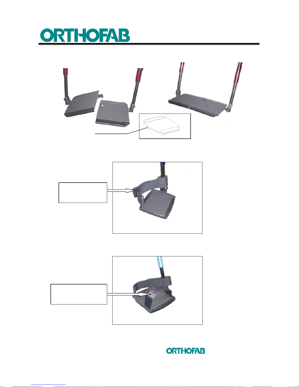
4.1.4 TO CHANGE THE ANGLE OF THE FULL LENGTH FOOTPLATE
Figure 3 : To change the angle of the full lenght footplate.
4.1.5 DEPTH ADJUSTMENT OF THE HEEL LOOPS
Figure 4 : Depth adjustment of the heel loops.
4.1.6 ADJUSTMENT OF THE TOE LOOPS
Figure 5 : Adjustment of the toe loops.
Angle adjustment
See section 4.1.3
Pull the "Velcro" and
adjust at the needed
length.
Pull the "Velcro" and
adjust at the needed
length.
Page 17
4 SETUP INSTRUCTIONS
17
inc
All rights reserved
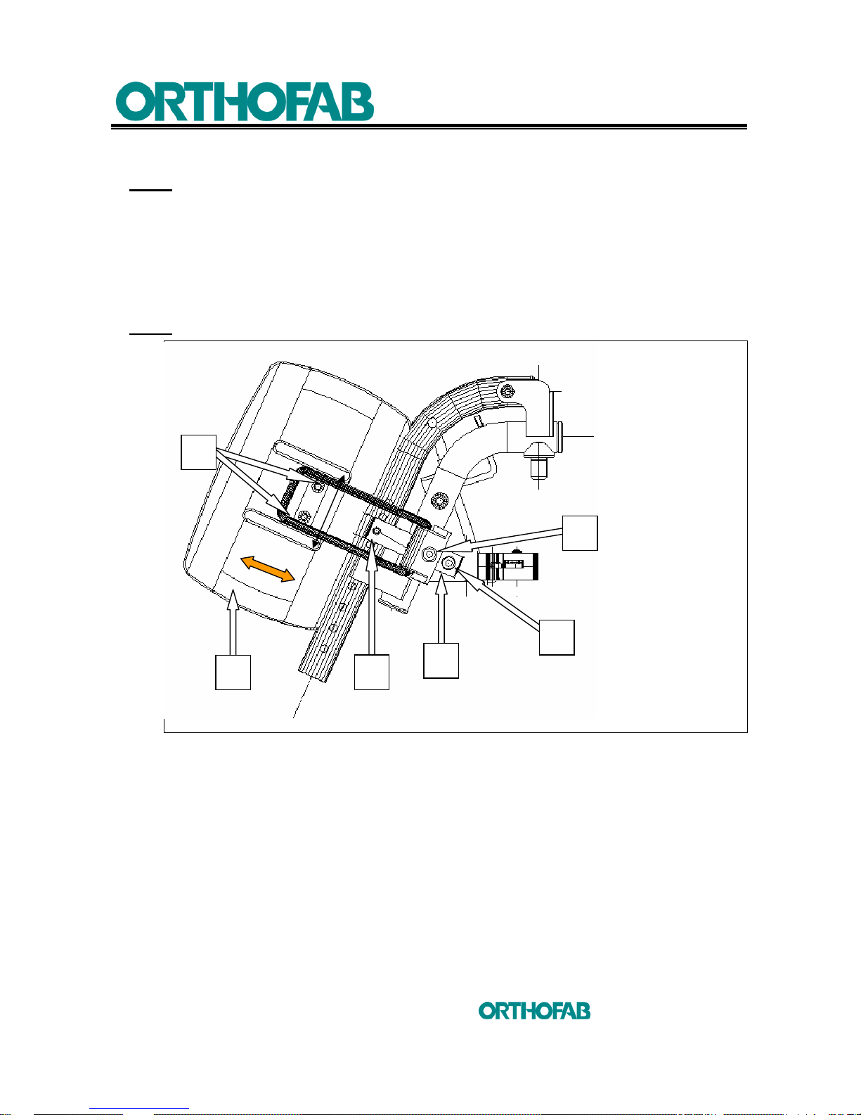
4.1.7 TO CHANGE THE HEIGHT OF THE CALF PAD
NOTE: The calf pad is adjustable in height, depth and width (see; figure 6).
a) To adjust the calf pad height :
1. Loosen screw (A) using a 5 mm Allen key ;
2. Slide support (B) until you reach the adequate position ;
3. Put back in place screw (A) and tighten firmly.
NOTE
: The calf pad is not adjustable in height with the articulated legrest.
Figure 6 : Calf pad adjustment.
4.1.8 TO CHANGE THE POSITION OF THE CALF PAD
b) To adjust the width :
1. Loosen screws (C) using a 4 mm Allen key ;
2. Slide calf pad (D) until you reach the adequate position ;
3. Tighten screws (C).
c) To adjust the depth :
1. Loosen screw (E) using a 5 mm Allen key ;
2. Loosen screw (F) ;
3. Adjust at the needed position and tighten screws (E) and (F).
A
B
C
D
E
F
Page 18
4 SETUP INSTRUCTIONS
18
inc
All rights reserved
4.2 ARMREST
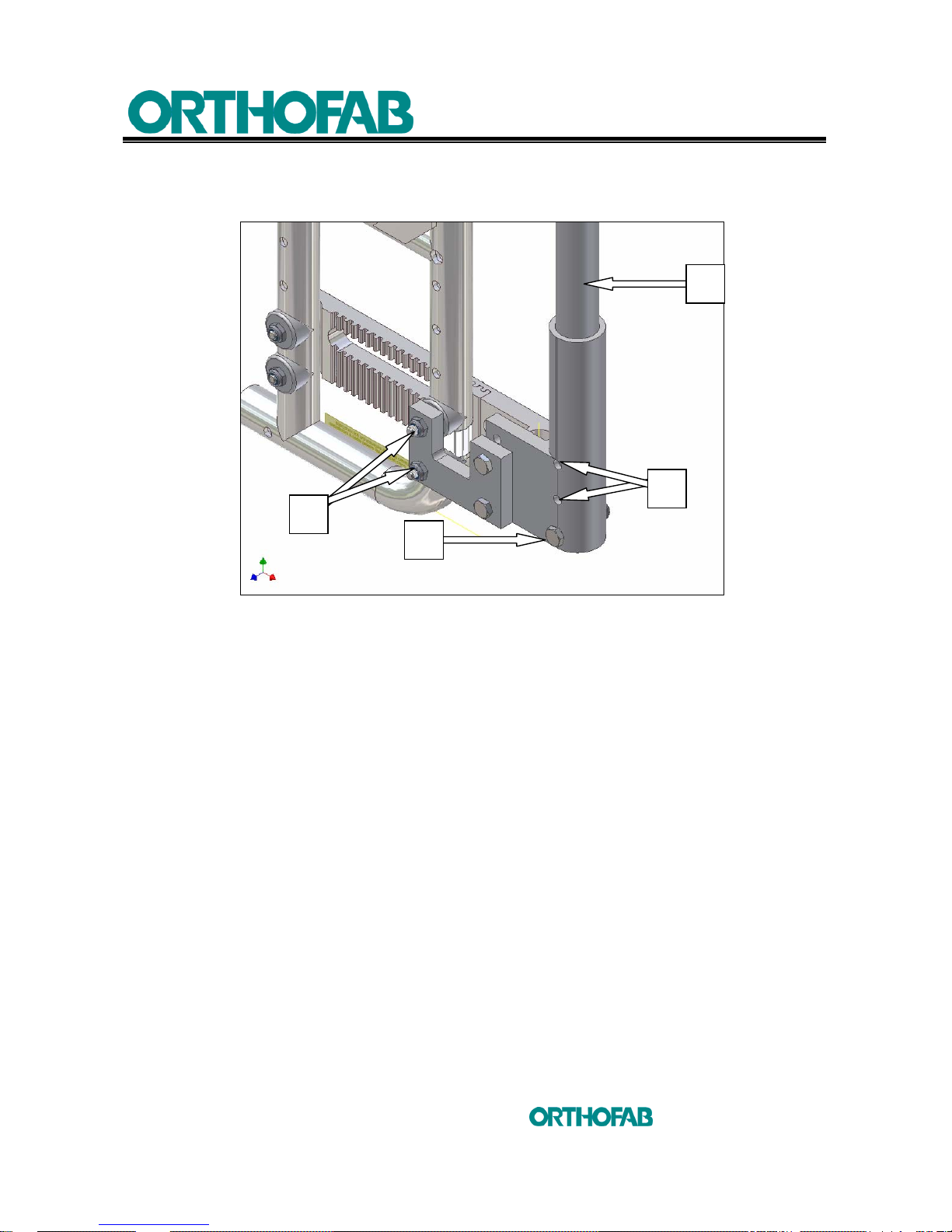
4.2.1 HEIGHT ADJUSTMENT, REMOVABLE, SWINGAWAY ARMREST
Figure 7 : Height adjustment, removable, swingaway armrest (A).
The height can be adjusted in 2 ways (see; figure 7) ;
1. By positioning the support screw (B) in the selected adjustment hole (C) using a
7/16" key ;
2. Installing the base of the armrest to a different height on the wheelchair frame
using the adjustment screws (D).
4.2.2 RIGID SIDEGUARD
TO ADJUST THE HEIGHT :
In order to maximize rigidity and to reduce movement, it is preferable to install the support
(A) as close as possible to the seat.
The height can be adjusted in 2 manners s (see; figure 8);
a) Adjustment of the support (A):
1. Using a 5 mm Allen key and unscrew the (B) bolt;
2. Install the support (A) at the needed position;
3. Tighten back the screws (B).
D
B
A
C
Page 19
4 SETUP INSTRUCTIONS
19
inc
All rights reserved
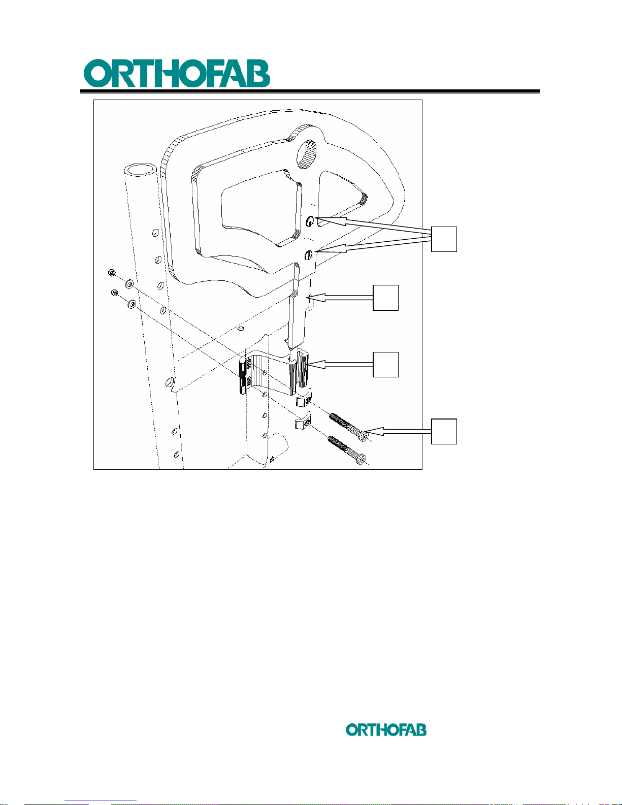
Figure 8 : Clothes guard adjustment.
b) Rod (D) adjustment :
1. Using a flat screwdriver of 1 cm x 1 mm; unscrew screws (C) and remove the two
(2) shoulder nuts (non illustrated) ;
2. Slide the rod (D) until you reach the needed height ;
3. Put back screws (C) and shoulder nuts and tighten.
B
A
D
C
Page 20
4 SETUP INSTRUCTIONS
20
inc
All rights reserved
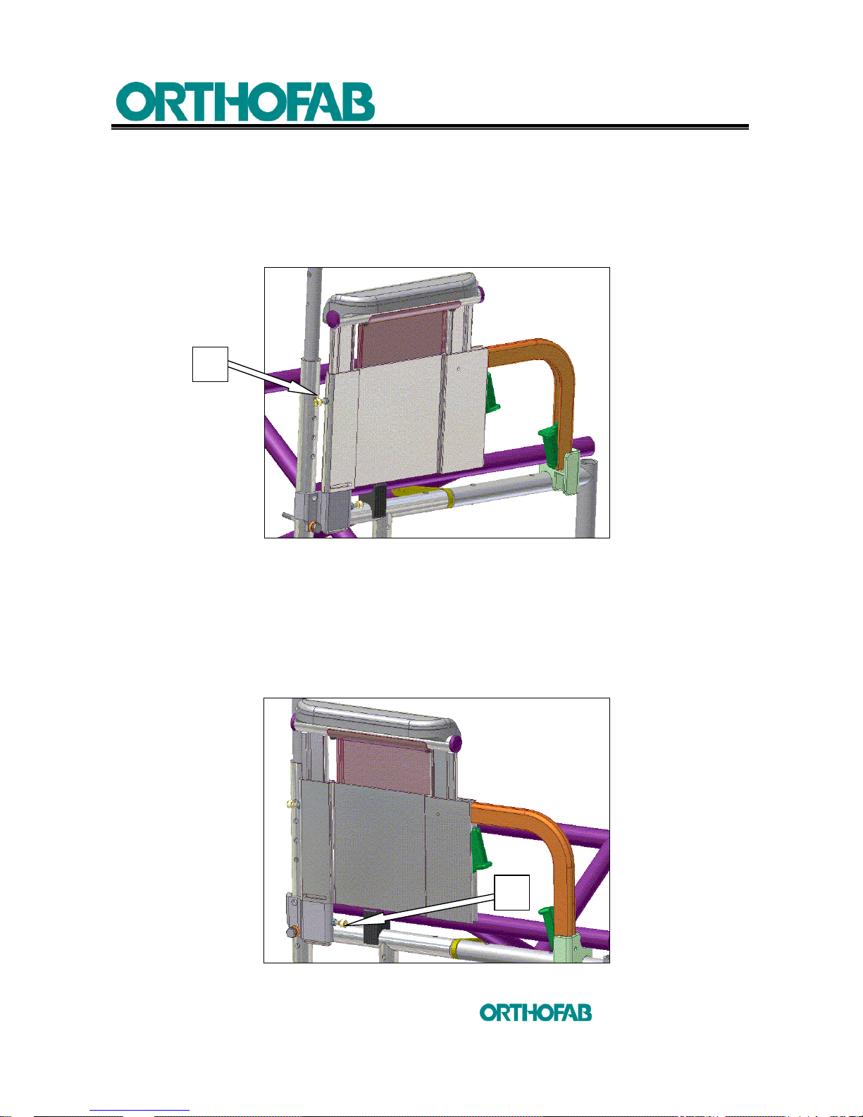
4.2.3 REMOVABLE “U” SHAPE SWINGAWAY ARMREST
4.2.3.1 TO PROHIBIT ADJUSTMENT IN HEIGHT
The screw (A) located at the back of the armrest gives the possibility of prohibiting the
adjustment in height of the armrest. To prohibit the height adjustment, loosen the
counter-nut (8 mm key), screw (4 mm Allen key) the bolt (A) in the hole and tighten back
the counter-nut (see; figure 9-A).
Figure 9-A : "U" shape armrest to prohibit the height adjustment.
4.2.3.2 PROHIBIT REMOVING OF THE ARMREST
The (A) screw located at the base of the armrest, gives the possibility of installing in a
permanent way the armrest to the wheelchair. This removes the "DETACHABLE" function
of the armrest while preserving the swingaway possibility. Loosen the counter-nut (8 mm
key), and screw (4 mm Allen key) the bolt (A) in the hole and tighten back the counter-nut.
(see; figure 9-B).
Figure 9-B : "U" shape armrest to prohibit removing.
A
A
Page 21
4 SETUP INSTRUCTIONS
21
inc
All rights reserved
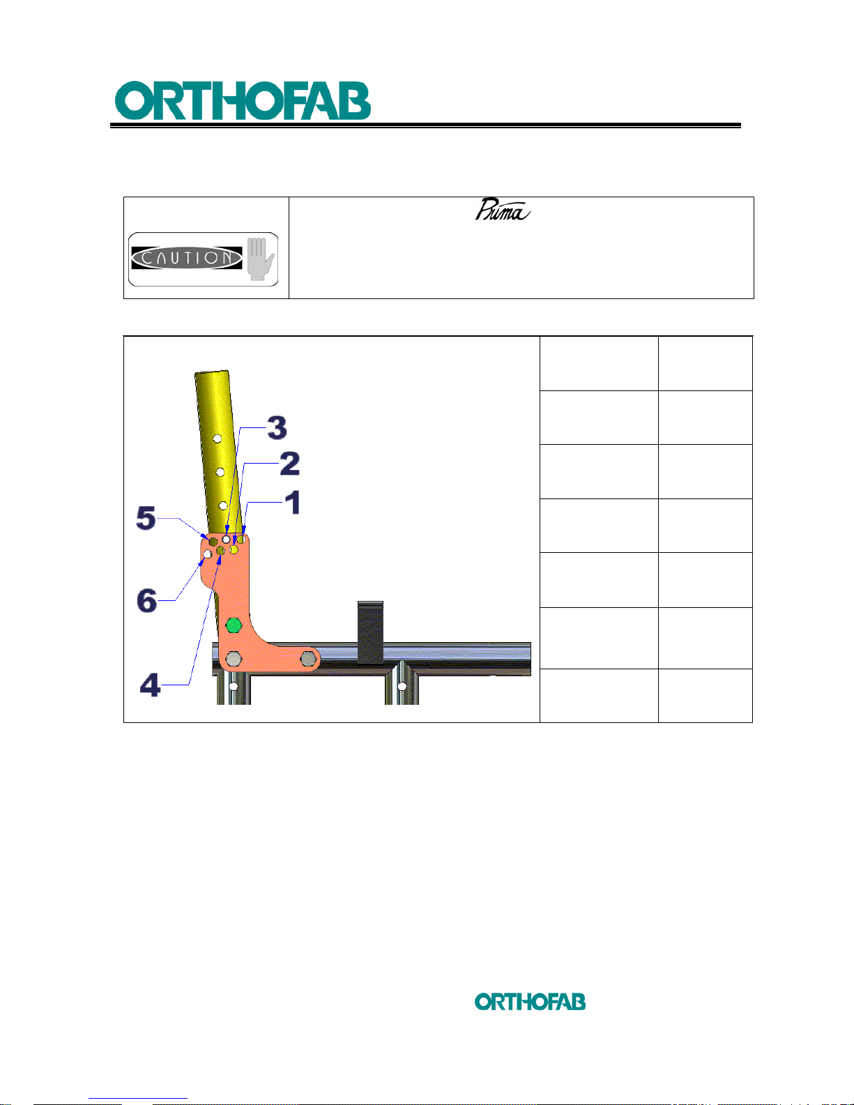
4.3 ADJUSTABLE BACKREST ANGLE
4.3.1 TO CHANGE THE BACKREST ANGLE
POSITION ANGLE
1 -5°
2 0°
3 5°
4 10°
5 15°
6 20°
Table 1 : To change the backrest angle.
The adjustments of your wheelchair must be made by
a health care professional. Inadequate adjustments can cause
wounds and/or damage to the user, the caregiver, the
wheelchair or the environment.
Page 22
4 SETUP INSTRUCTIONS
22
inc
All rights reserved
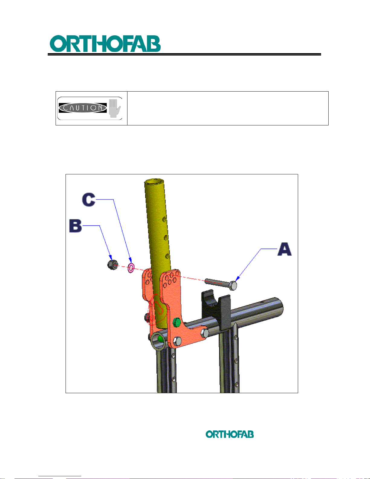
1. Unscrew nut (B) (using a 7/16" key) on each backrest post (see; figure 10) ;
2. Place yourself behind the backrest, then withdraw the screw (A) on each side ;
Once the screws (A) are removed, the backrest can be folded
back completely backwards.
3. Replace the (A) screws of the backrest in one of the six (6) holes of assembly on
the adjustment plate to obtain –5°, 0°, 5°, 10°, 15°, 20° as shown in the table 1 ;
4. Tighten the screw (A) and nut (B) of each backrest post, do not forget the (C)
washers
.
Figure 10 : To change the backrest angle.
Page 23
4 SETUP INSTRUCTIONS
23
inc
All rights reserved
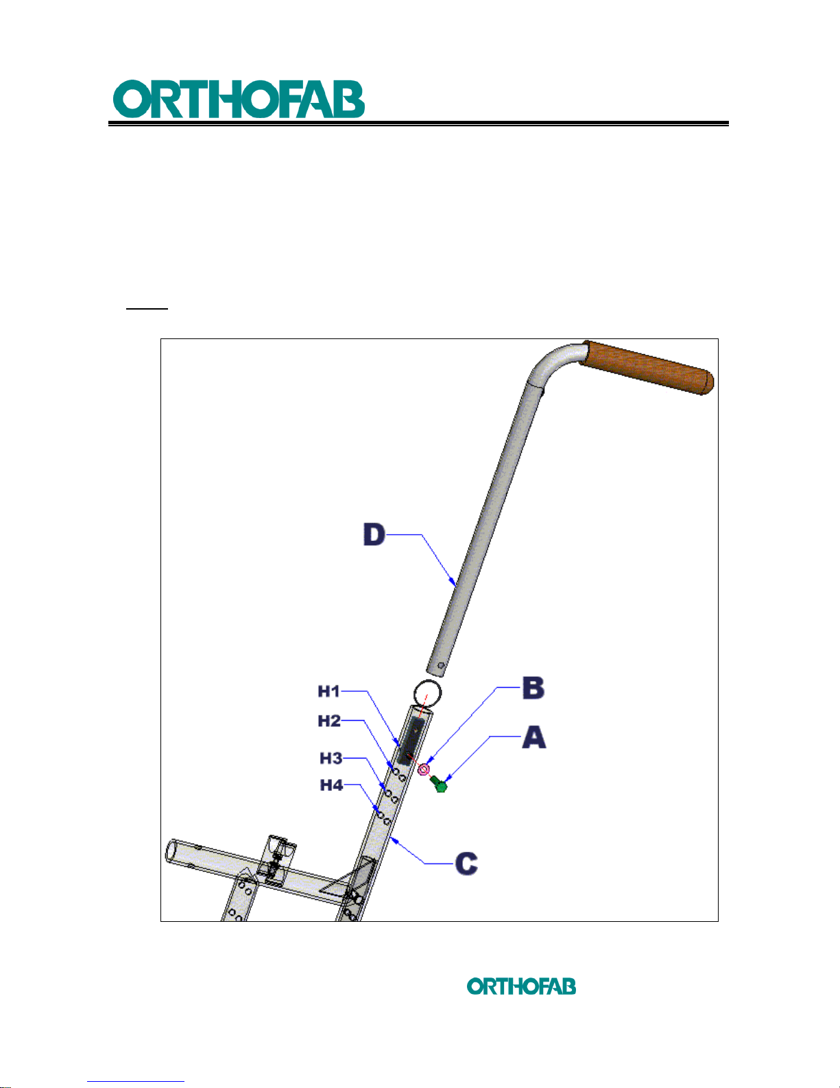
4.3.2 TO CHANGE THE BACKREST HEIGHT
To change the height of the backrest (see; figure 11) :
1. Unscrew the (A) screw (using a 7/16" key) located on each backrest structure (C).
2. Choose the height and bring the threaded part of the backrest post (D) at the
height (H1, H2, H3 or H4) on the backrest structure (C) and tighten firmly the (A)
screw, do not forget the (B) washer.
NOTE: There are 4 possible adjustment heights, no matter which rear frame will be
choose.
Figure 11 : To change the backrest height.
Page 24
4 SETUP INSTRUCTIONS
24
inc
All rights reserved
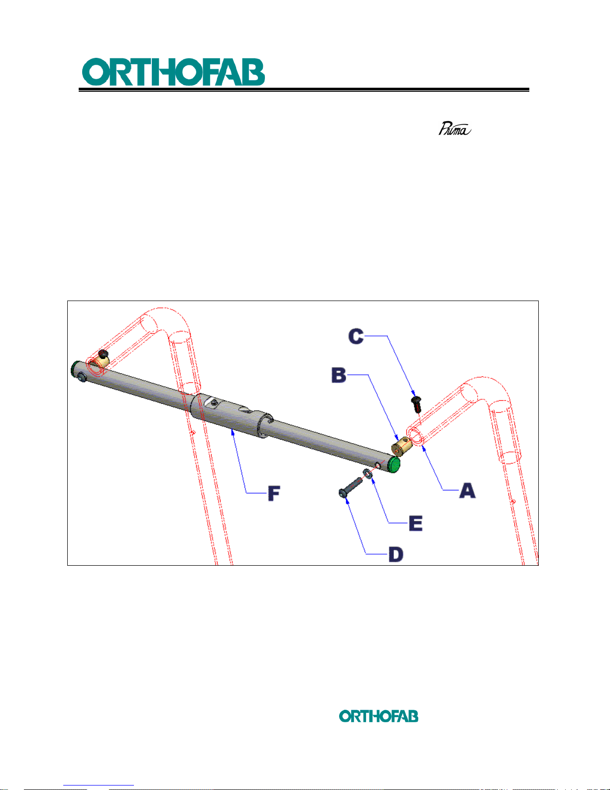
4.3.3 PUSH HANDLES INSTALLATION
For reinforcement reasons a push handle bar can be assembled on the
to do it :
a) PUSH HANDLE (see; figure 12) :
1. Cut out the rubber handle on the backrest post (A) flush to the steel tubing ;
2. Insert the push handle fixation bushing (B) in the hole at the end of the backrest
post (A) ;
3. Clear a little the rubber on the backrest post and tighten the (C) screw, using a
4 mm Allen key, in the fixation bushing (B), replace the rubber over the (C) screw ;
4. Using a 4 mm Allen key, tighten firmly the (D) screw and the (E) washer at the end
of the fixation bushing (B) to fix the push handle (F) ;
5. Do this procedure on both sides of the wheelchair.
Figure 12 : Push handle assembly.
Page 25
4 SETUP INSTRUCTIONS
25
inc
All rights reserved
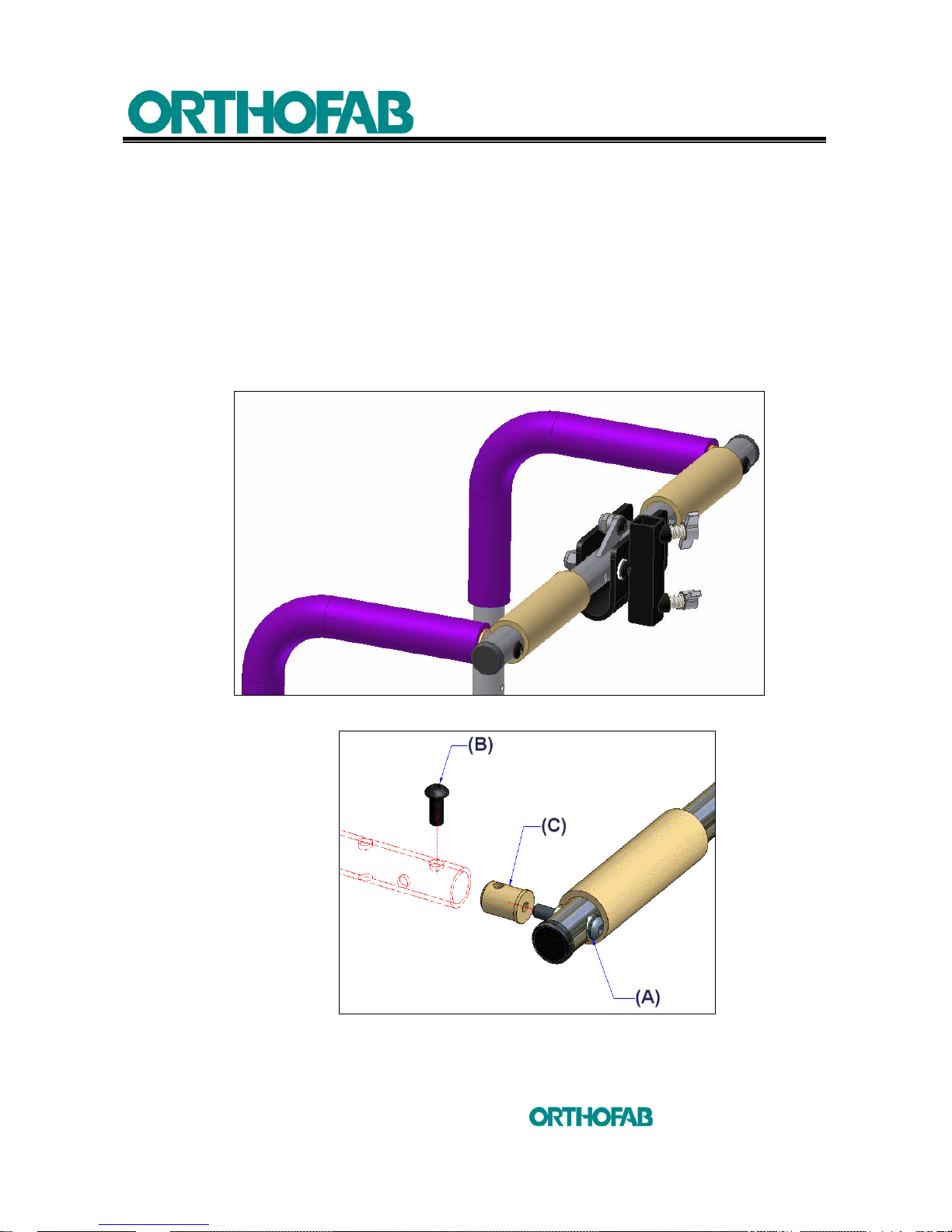
b) PUSH HANDLE WITH HEADREST SUPPORT (see; figures 13-A and B) :
1. Cut out the rubber handle on the backrest post flush to the steel tubing ;
2. Insert the push handle fixation bushing (C) in the hole at the end of the backrest
post (see; figure 13-B) ;
3. Using a 4 mm Allen key, tighten firmly the (B) screw in the fixation bushing (C) and
also the (A) screw at the end of the fixation bushing (C) to finish the assembly ;
4. Once the assembly will be finish it should be as shown at figure 13-A (the rubber
handle should cover completely the (B) screw ;
5. Do this procedure on both sides of the wheelchair.
Figure 13-A : Push handle with headrest support assembly.
Figure 13-B : Push handle fixation on the backrest post.
Page 26
4 SETUP INSTRUCTIONS
26
inc
All rights reserved
4.4 DYNAMIC BACKREST
4.4.1 DYNAMIC BACKREST INSTALLATION
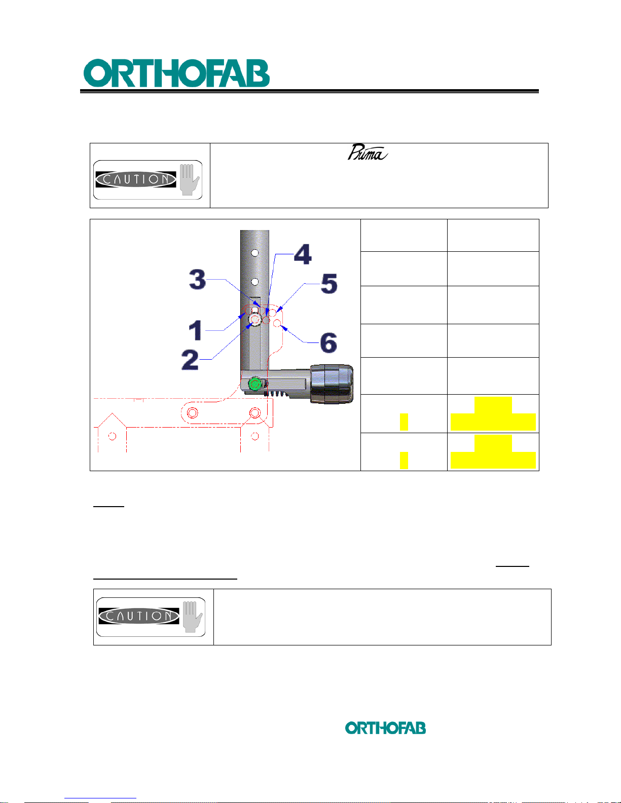
POSITION ANGLE
1 -5°
2 0°
3 5
° (std)
4 10°
5
NON-
AVAILABLE
6
NON-
AVAILABLE
Table 2: Dynamic backrest angles adjustment positions.
NOTE:
The way to change the dynamic backrest angle, is the same as per section 4.3.1,
the only difference with the dynamic backrest is to don’t forget to move the nylon washers
(C) following the new angle position (see; figure 14).
Consult the table 2 above to know the possible adjustment angles and to tighten
the screws at 20 pounds/inch.
It is important to use only the 1 to 4 positions of the table 2
above, to not damage the dynamic backrest system.
The adjustments of your wheelchair must be made by
a health care professional. Inadequate adjustments can cause
wounds and/or damage to the user, the caregiver, the
wheelchair or the environment.
Page 27
4 SETUP INSTRUCTIONS
27
inc
All rights reserved
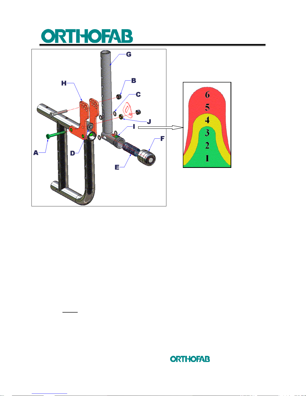
Figure 14: Dynamic backrest installation on the wheelchair.
1. Determine at which angle the backrest should be installed ;
2. Take the backrest structure tubing (G) and insert the compression piston (D) equal
to the oblong hole in the same way as shown at figure 14 above. The compression
piston (D) should be sprayed with grease before insertion.
3. Spray with grease the 4 nylon washers (C) and put two of them on the inside in line
with the bottom holes on the anchor structure (H). The grease should retain the
nylon washers stick to the anchor structure (H).
4. Take the backrest structure tubing (G) with the compression piston (D) and install it
on the anchor structure (H). Once that the two (C) nylon washers, the
compression piston (D) and the oblong hole on the backrest structure tubing will be
all aligned, insert the (A) screw, the (J) washer and tighten the (B) screw, using
two 7/16" key.
• NOTE: Tighten the screws at 20 pounds/inch. This tightening force should allow
the dynamic backrest assembly to move freely.
5. Take the two others (C) nylon washers and put them on the inside in line with the
adjustment angle holes on the anchor structure (H).
Page 28

4 SETUP INSTRUCTIONS
28
inc
All rights reserved
6. Adjust the backrest structure tubing (G) at the desired angle and once the (C)
nylon washers and the holes in the backrest structure tubing (G) will be all aligned,
insert the full threaded (A) screw and tighten the (B) nut, using two 7/16" key (see;
the note at step 4, in reference to know about the tightening force to use).
7. Insert the (E) spring beforehand sprayed with grease in the bottom part of the
backrest structure tubing (G) shown at figure 14.
8. Spray with grease the threaded part of the spring tension adjustment handle (F).
9. Screw the spring tension adjustment handle (F) on the bottom part of the backrest
structure tubing (G) until you can see only two threads (this is the NEUTRAL
position at this position the spring is not compressed yet).
4.4.2 DYNAMIC BACKREST ADJUSTMENT
It is possible to choose 3 different types of springs with the dynamic backrest. 3 springs
with different compression hardness. The RED spring (soft tension), the BRONZE spring
(regular tension) and the GREEN spring (hard tension).
1. Insert the selected (E) spring in the bottom part of the backrest structure tubing (G)
and screw the spring tension adjustment handle (F) until you can not see any
threads (the spring will be a little bit compressed) (see; figure 14).
2. Refer to the graduated sticker (I) to know the maximum compression of each
springs (see; figure 14). For example
; the green spring, will reach its maximum
compression, when the handle (F) will be in line with the number 3 on the sticker
(I).
3. The final adjustment will depend on each user comfort. Moreover, this adjustment
could be different on each backrest post.
Never put your hands on the spring tension adjustment
handle (F) during somebody use the dynamic backrest.
Page 29
4 SETUP INSTRUCTIONS
29
inc
All rights reserved
4.5 SEAT
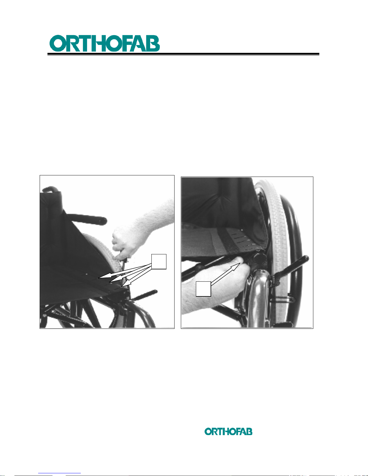
4.5.1 SLING SEAT
Sling seat tension adjustment :
To stretch the sling seat, remove the seat cushion and do the following
(see; figures 14-A et B).
1. Loosen (A) screws ;
2. Stretch the sling by pulling on the (B) part bended un der the seat, the (B) part is
retained by a “Velcro” strip ;
3. Tighten (A) screws.
Figure 14-A: Sling seat adjustment. Figure 14-B
A
B
Page 30
4 SETUP INSTRUCTIONS
30
inc
All rights reserved
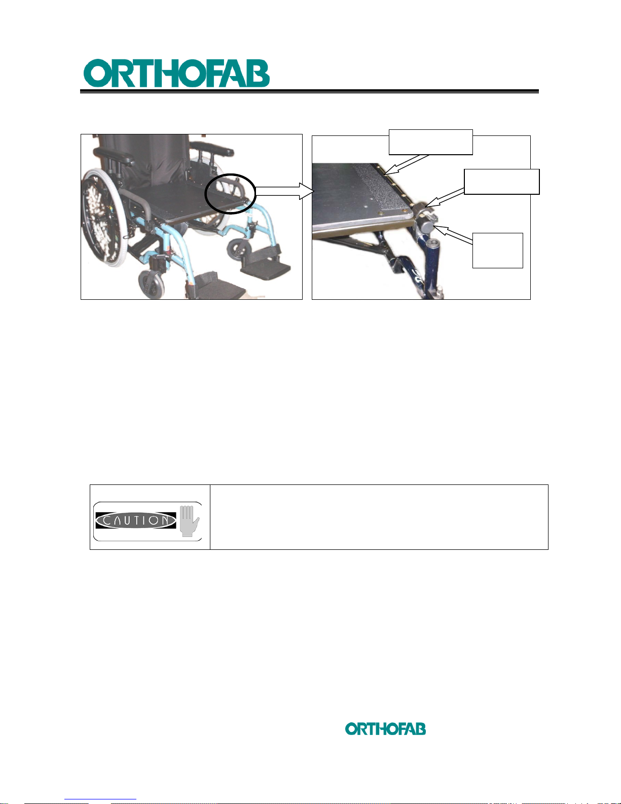
4.5.2 RIGID SEAT
Figure 15-A: Rigid seat installation. Figure 15-B
a) To remove the rigid seat :
• To remove the rigid seat, grab the rigid seat by the handle and pull upwards to
release the seat from the side frame.
b) To install the rigid seat :
• Push the rear part of the rigid seat up to the upholstery of the backrest. Locate the
hooks at the front of the seat and apply against the end stop located on both side
of the wheelchair on the side frame. Make sure that the rear hooks are in contact
with the side frame.
It is important to secure the hooks right by the end stops.
SIDE FRAME
HOOK
END
STOP
Page 31
4 SETUP INSTRUCTIONS
31
inc
All rights reserved
4.6 ADJUSTABLE ISCHIATIC PROFILE SEAT CUSHION
NOTES
:
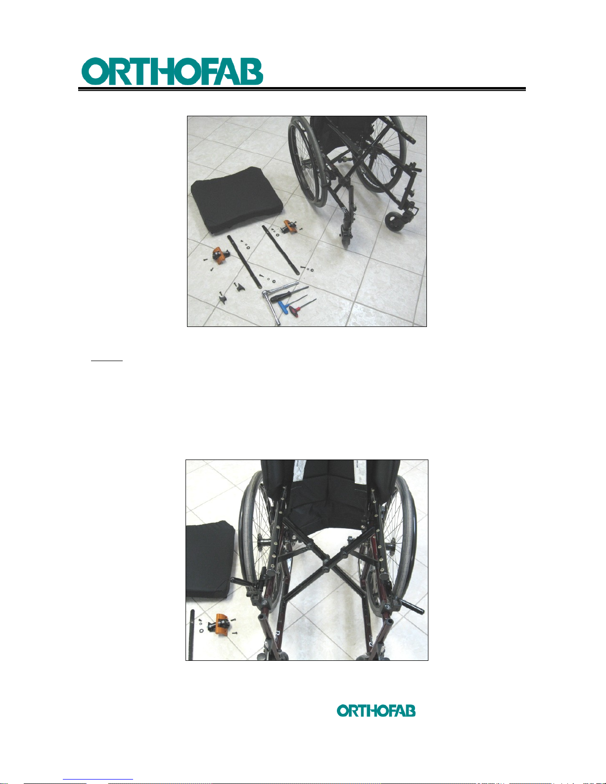
1. This product installation can be done in 4 steps. The tools required are: 3 mm and
5/32" Allen key, also a medium Phillips screwdriver (see; figure 16-A).
2. The postural adjustment can be done using a ratchet tool with an extension and a
1/2" socket (see; figure 16-A).
The installation of your adjustable ischiatic profile seat
cushion
must be made by a health care professional.
Inadequate adjustments can cause wounds and/or damage to
the user, the caregiver, the wheelchair or the environment.
Please note that the anchor systems are factory assembled
with hardware which should not be dismantled nor reinstalled.
It is very important that the anchor systems stay untouched
and that no effort to replace parts should be done. In case of
doubt or damage, please change the complete anchor system
approved by Orthofab. Failure to respect this warning can
cause wounds and/or damage to the user, the caregiver, the
wheelchair or the environment.
The adjustments of your adjustable ischiatic profile seat
cushion
wheelchair must be made by a health care
professional. Inadequate adjustments can cause wounds
and/or damage to the user, the caregiver, the wheelchair or
the environment.
Page 32
4 SETUP INSTRUCTIONS
32
inc
All rights reserved
4.6.1 ADJUSTABLE ISCHIATIC PROFILE SEAT CUSHION INSTALLATION
Figure 16-A: Hardware and tools needed to install the ischiatic seat cushion.
Step 1 :
1. Fold slightly the wheelchair and keep it like that until the last step of this installation
(see; figure 16-B).
2. Remove the armrests and legrests.
3. Place the restraint belt on the backrest, to clear the side frame.
4. Engage the parking brakes.
5. Remove, if necessary, the sling seat or the rigid seat.
Figure 16-B: Fold slightly the wheelchair .
Page 33
4 SETUP INSTRUCTIONS
33
inc
All rights reserved
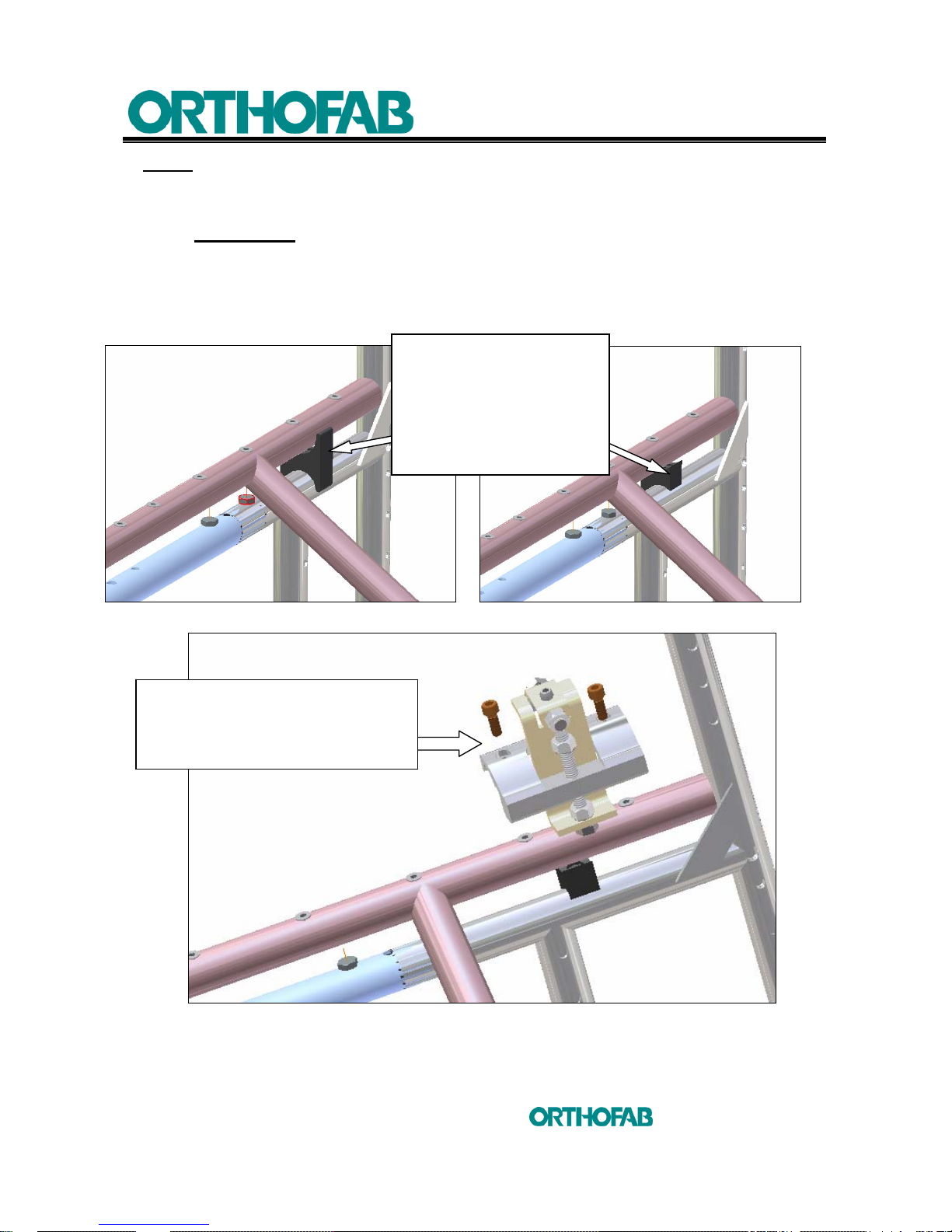
Step 2 :
1. Using a Phillips screwdriver, replace the collapsible brace frame supports by the
truncated one (see; figures 16-C and D).
2. IMPORTANT: The truncated side of the collapsible brace frame supports must be
installed towards the inside of the wheelchair.
3. Using a 4 mm Allen key, place and install the adjustment mechanisms on each
side frame. These mechanisms are made to fit towards the inside of the
wheelchair without create any interferences (see; figure 16-E).
Figure 16-C: To change the brace frame supports. Figure 16-D: Truncated brace frame support.
Figure 16-E: Ischiatic seat cushion adjustment mechanism installation.
Remove the collapsible
brace frame supports and
replace them by the
truncated one.
Flat side towards the
inside of the wheelchair.
Install the ischiatic seat cushion
adjustment mechanisms on both
side of the wheelchair towards the
inside.
Page 34
4 SETUP INSTRUCTIONS
34
inc
All rights reserved
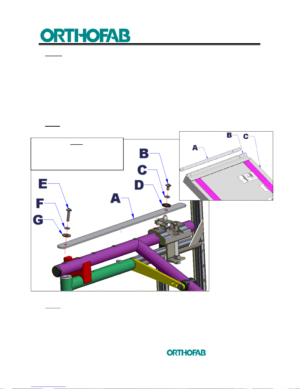
Step 3 :
1. Insert the metal flat bar (A) in the ischiatic seat cushion (C) by making sure to align
the right size holes of the metal flat bar (A) with those ones in the (B) ischiatic seat
cushion sleeve (see; figure 16-F).
2. With the wheelchair slightly folded, place the 45° corners of the ischiatic seat
cushion towards rear and fix the front part of the seat cushion on the side frame,
using a 3 mm Allen key, by placing the (G) washer, (F) lock-washer and the (E)
screw. The rear part of the seat cushion will be fixed on the adjustment
mechanism by placing the (D) flat washer, (C) lock-washer and the (B) screw.
3. Insert all the hardware but do not fix it completely at this step.
NOTE : Keep the wheelchair folded at this step. Do not unfold it until to finish the
installation : Step 4.
Figure 16-G: Ischiatic seat cushion metal flat bar (A) installation.
Step 4 :
1. Before to tight the (B) and (E) screws, be sure that you installed all the hardware
correctly, check that the screws turn freely in the threaded inserts.
2. Tighten the 4 screws (2 on each side), using a 3 mm Allen key.
3. Unfold the wheelchair (open) and do the adjustment of the seat at section 4.6.2.
Figure 16-F
NOTE:
THE METAL FLAT BAR IS SHOWN
WITHOUT THE ISCHIATIC SEAT
CUSHION TO A BETTER DRAWING
COMPREHENSION.
Page 35
4 SETUP INSTRUCTIONS
35
inc
All rights reserved
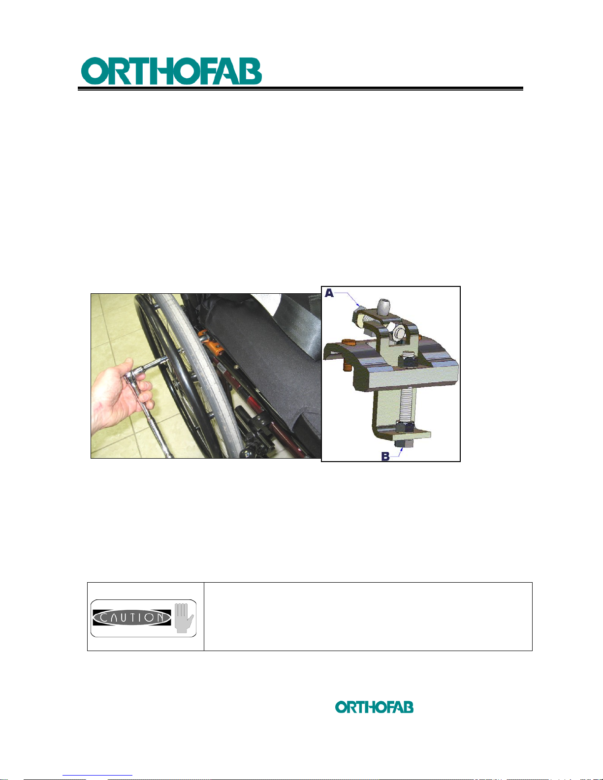
4.6.2 ISCHIATIC SEAT CUSHION ADJUSTMENT
The adjustable ischiatic profile seat cushion is made to allow the perfect adjustment when
the user is seated. The occupational therapist will be able, by direct palpation, to decide
which adjustment will be required.
There are two types of adjustment: LATERAL and in ELEVATION. It is recommended to
remove the armrests or to swing them away to provide access to the lateral adjustment
screws on each side of the wheelchair. The elevation adjustment is made under the seat
by taking position behind the wheelchair.
Using a ratchet with an extension and a 1/2" socket, place yourself on one side of the
wheelchair. Place the socket on the head of the (A) screw and turn clockwise to release
the tension in the ischiatic seat cushion. To turn the (A) screw counterclockwise will
stretch the seat cushion. Repeat the procedure on the other side for the 2
nd
lateral
adjustment screw (see; figure 17).
Figure 17: Ischiatic seat cushion, lateral adjustment.
If necessary, you can proceed to the elevation adjustment. Place yourself behind the
wheelchair, in the way to get access to the (B) elevation adjustment screw (see; figure
17). It is possible here to raise or lower the seat cushion only by turning clockwise or
counterclockwise the (B) elevation adjustment screw. Work together with the
occupational therapist who hand checked the user and give feedback (with the user) on
the adjustment quality. This adjustment can compensate for hips obliquities, scoliosis or
simply to adjust a comfort position for a hand and foot propulsion.
Make sure to never force the lateral and elevation adjustment
screws, these screws have a set range and exceed this range
can cause damage to the product components. The
adjustment screws are installed in the way that you will never
have to dismantle them from the adjustment mechanism.
Page 36
4 SETUP INSTRUCTIONS
36
inc
All rights reserved
4.7 FRONT CASTERS
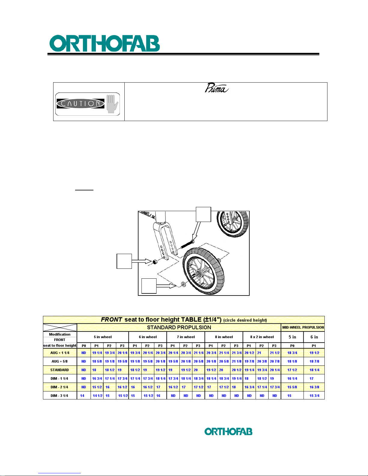
4.7.1 TO CHANGE THE MODEL OR THE HEIGHT OF THE FRONT CASTER
1. Remove the (A) screw, using a 1/2" key, and the (B) nut which maintains the front
caster wheel to the fork (see; figure 18) ;
2. Remove the wheel from the fork ;
3. Remove the (C) spacers ;
4. Install the (A) screw in the selected hole on the fork ;
5. Invert the procedure to reinstall the wheel on the fork.
NOTE : Refer to table 3 below for the choice of height . When the diameter or
the front wheel height is changed, it is important to reset the
perpendicular adjustment (see; section 4.7.2).
Figure 18: To change the model of the front caster.
Table 3: (Front) seat to floor height according to the chosen wheel size and the frame.
The adjustments of your wheelchair must be made by
a health care professional. Inadequate adjustments can cause
wounds and/or damage to the user, the caregiver, the
wheelchair or the environment.
A
B
C
Page 37
4 SETUP INSTRUCTIONS
37
inc
All rights reserved
4.7.2 FORKS PERPENDICULAR ADJUSTMENT
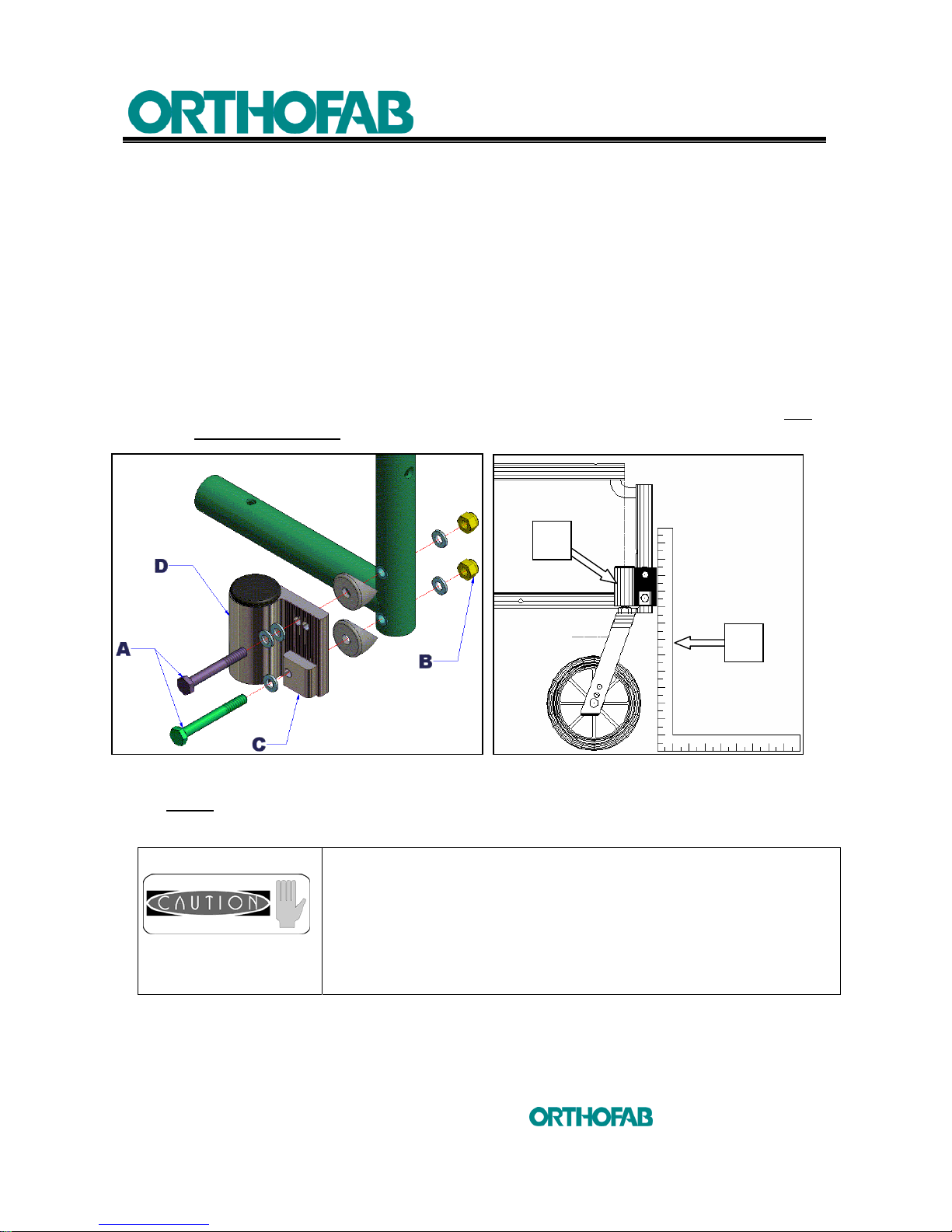
To make sure that the wheelchair will easily pivot and will keep a straight trajectory, it is
important to maintain an angle of 90° between the ground and the caster stem axle. To
do it, follow the instructions below (see; figures 19-A and B).
1. Loosen (A) screws with a 7/16" key (see; figure 19-A) ;
2. Loosen (B) nuts with a 7/16" key, up to the point where the small teeth on part (C)
will disengaged from the mating teeth on part (D) ;
3. Align the flat side of the caster stem (D) on a square ruler (E) (see; figure 19-B) ;
4. Realign the teeth of the adjustment plate (C) with the teeth of the caster stem (D) ;
5. Tighten the (A) screws and (B) nuts firmly, use a torque wrench and torque at 100
to 120 Pounds/inch.
Figure 19-A: Perpendicular adjustment. Figure 19-B
NOTE
: Each tooth allows an adjustment of 1/16 inch. If you turn the (C) plate 180°, you
will get an adjustment of 1/32 inch.
For minimal obstruction and for a better handiness, it is
preferable to assemble the caster stem backwards (see;
figures 19-A and B). However, with a seat depth of 16 inches,
some configurations of front caster and rear wheels diameter
can generate interferences between the front caster and the
rear wheels. It is then necessary to assemble the caster stem
forward.
D
E
Page 38
4 SETUP INSTRUCTIONS
38
inc
All rights reserved
4.8 REAR WHEELS
4.8.1 TO CHANGE THE MODEL OF REAR WHEELS
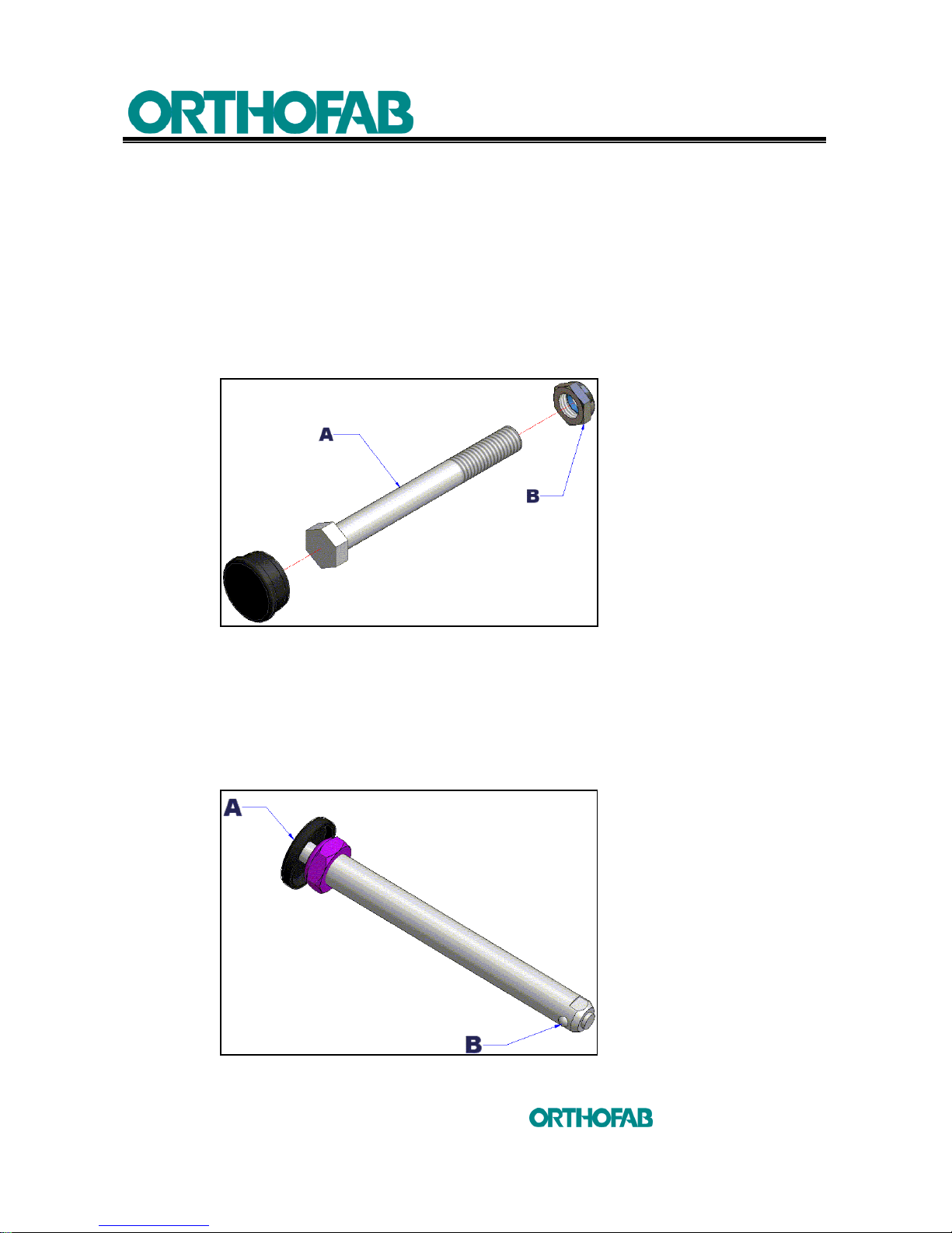
The modification of the seat to floor height can require a change of the rear wheels
diameter. To do it :
a)
THREADED AXLES
:
1. To remove the wheel, unscrew the (A) screw and (B) nut, using a 3/4" key ;
2. To put back the wheel in place, use a new nut. Avoid tightening the nut too much,
if you do, the wheel might have difficulty to turn (see; figure 20-A).
Figure 20-A: Threaded axle.
b)
QUICK RELEASE AXLES :
1. Push the (A) button and pull the wheel towards you. Handle the wheel from its
center part (see; figure 20-B) ;
2. To install, push the (A) button and insert the axle in the housing. Make sure that
the axle is locked in place in the housing by the blocking pins (B).
Figure 20-B: Quick release axle.
Page 39
4 SETUP INSTRUCTIONS
39
inc
All rights reserved
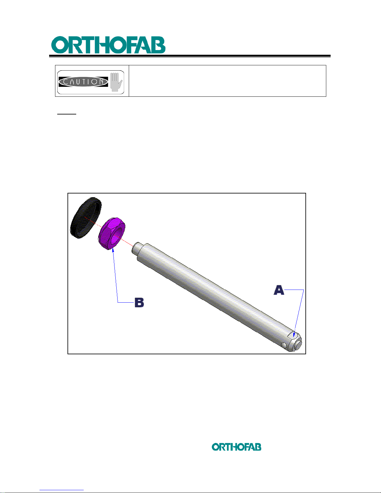
NOTE
: If the axle does not locked, it may requires an adjustment.
To do it (see; figure 20-C) :
1. Remove the axle from the housing ;
2. Use a 7/16" key, to maintain the end of the axle (A) ;
3. Use a 3/4" key, to tighten or loosen slightly nut (B);
4. Insert the axle in the wheel and carry out a test. (It is always
preferable to have a small side play, once the axle is locked ±
1/64”.)
Figure 20-C: Quick release axle adjustment.
Make sure that the two (2) blocking pins of the quick
release axle are released before using the wheelchair. The
blocking pins MUST exceed the housing for a perfect fit.
Keep the axle and the blocking pins clean.
Page 40
4 SETUP INSTRUCTIONS
40
inc
All rights reserved
4.8.2 CENTER OF GRAVITY ADJUSTMENT
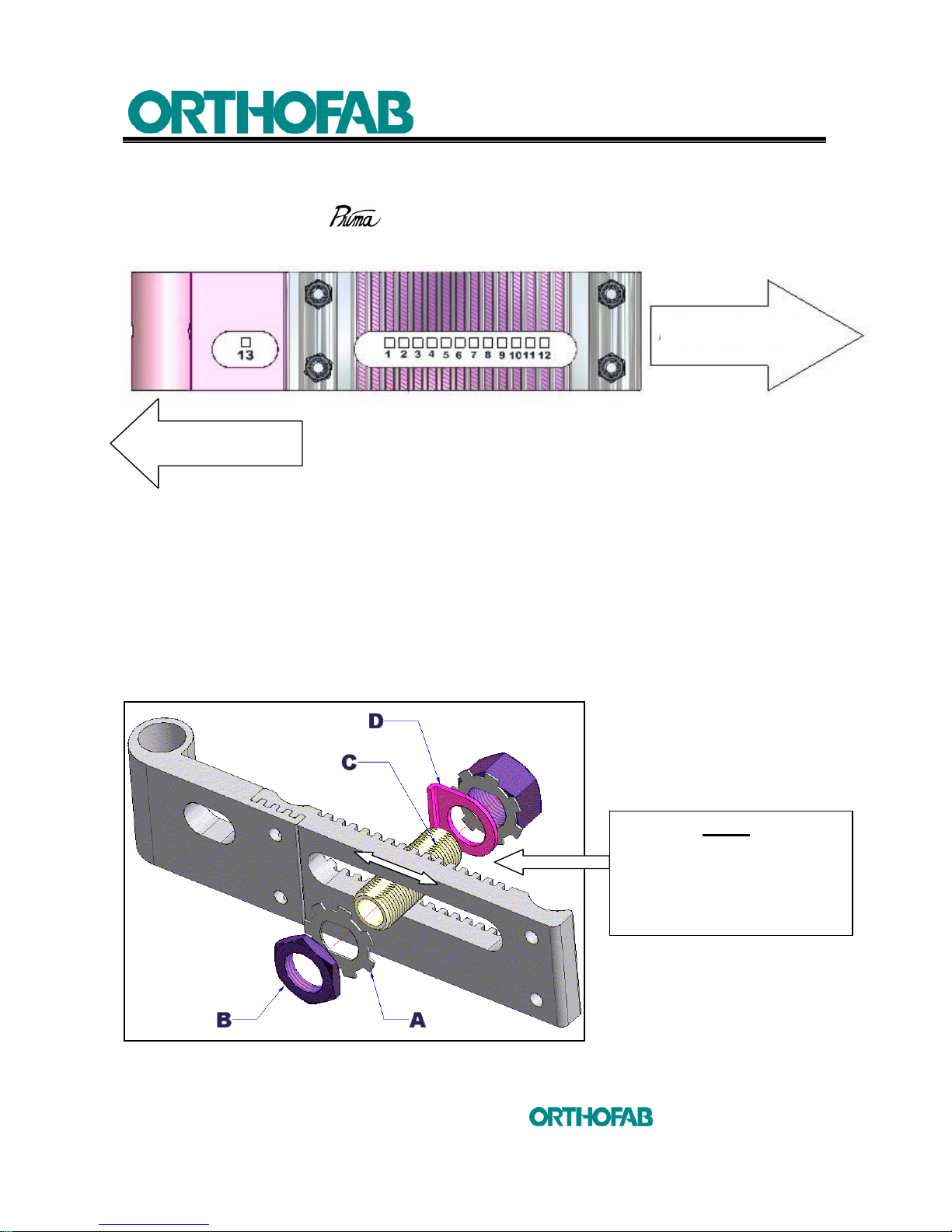
The adjustment of the center of gravity is necessary in order to preserve a good stability
of the wheelchair. The
allows thirteen adjustment (13) positions. The choice of
these positions is the responsibility of the occupational therapists or the clinicians.
The more the position of the wheel is placed towards rear, better is the wheelchair
stability (except for the 6 wheels configuration which is always stable).
To move forward or backward the rear axle (see; figure 21) :
1. Unf old the jam nut notch (A) to free nut (B) ;
2. Loosen the (B) nut with a 1 1/8" key, just enough to disengage the depth
positioning plate (D) ;
3. Position the housing (C) at the needed location ;
4. Replace the jam nut (A) and fold the notch over the (B) nut ;
5. Firmly tighten the (B) nut with a torque wrench (360 Pounds/inch).
Figure 21: To move forward or backward the rear axle.
FRONT OF WHEELCHAIR
6 wheels Prima
NOTE :
Make sure that the (C)
housings are located at the
same position on each side
of the wheelchair.
FRONT OF WHEELCHAIR
4 wheels Prima
Page 41
4 SETUP INSTRUCTIONS
41
inc
All rights reserved
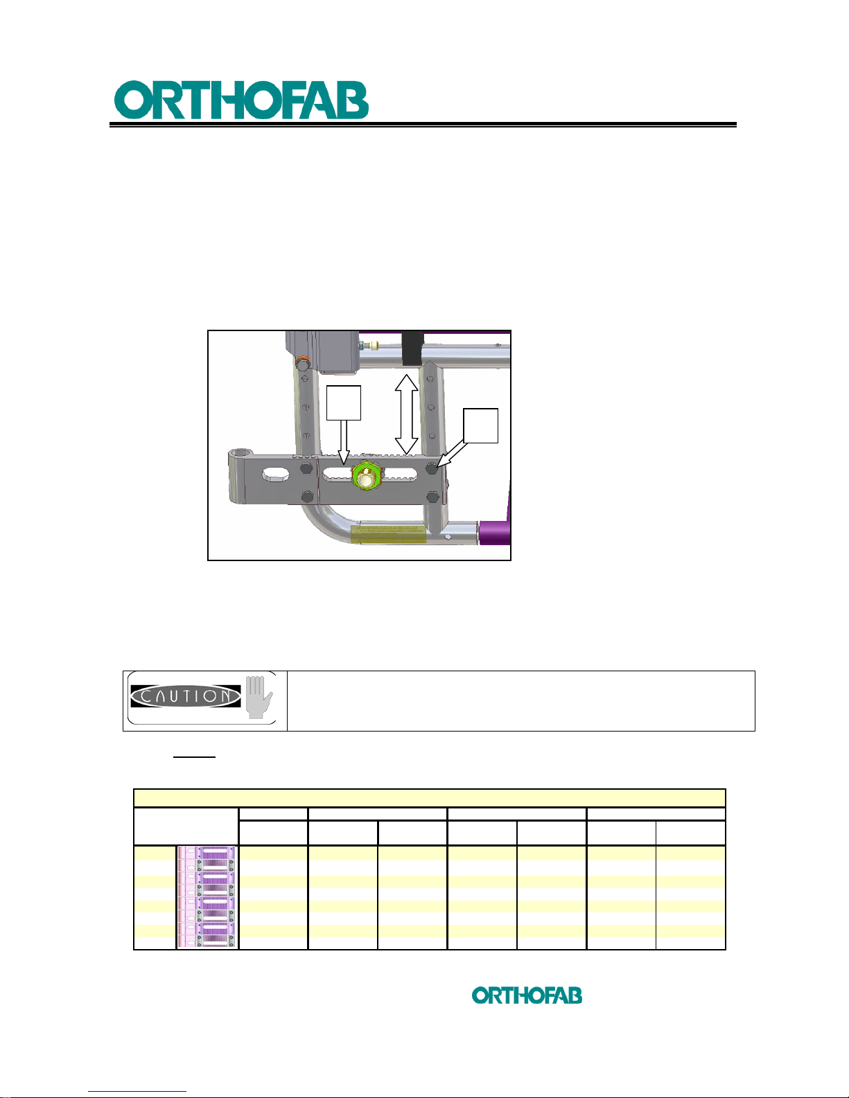
4.8.3 REAR HEIGHT ADJUSTMENT
To modify the rear height of the wheelchair, reposition the rear wheel housing plate
(see; figure 22).
To do it:
1. Remove the rear wheels. See; section 4.8.1 ;
2. Loosen the 4 screws (A) with a 7/16" key ;
3. Reposition the plate (B) at the needed height, with the saddles and washers ;
4. Tighten firmly the 4 screws (A) with new nuts (torque of 120 Pounds/inch) ;
Figure 22: Rear height adjustment.
5. Repeat this procedure on the other side ;
6. Replace the rear wheels ;
7. Repeat this procedure until the wheelchair is stable.
NOTE : When the diameter or the rear wheel height is changed, it is important to
reset the front wheels perpendicular adjustment (see; section 4.7.2).
Once the procedure is completed, it will be necessary to adjust
the parking brakes as per the instructions in section 4.9.1.
Adjust also the anti-tippers.
A
B
Table 4: Rear seat to floor height.
20" Wheel
1
13 3/8 14 3/8 13 3/4 15 1/4 14 5/8 16 1/8 15 1/2
2
14 15
14 3/8
15 7/8
15 1/4
16 3/4 16 1/8
3
14 5/8 15 5/8 15 16 1/2 15 7/8 17 3/8 16 3/4
4
15 1/4 16 1/4 15 5/8 17 1/8 16 1/2 18 17 3/8
5
15 7/8 16 7/8 16 1/4 17 3/4 17 1/8 18 5/8 18
6
16 1/2 17 1/2 16 7/8 18 3/8 17 3/4 19 1/4 18 5/8
7
17 1/8 18 1/8 17 1/2 19 18 3/8 19 7/8 19 1/4
8
17 3/4 18 3/4 18 1/8 19 5/8 19 20 1/2 19 7/8
Rear seat to floor height
15
Rear seat to floor
22" Wheel 24" Wheel 26" Wheel
Pneumatic
Pneumatic and
Semi pneumatic
Pneumatic and
Semi pneumatic
Polyurethane and
Hight pressure
Pneumatic and
Semi pneumatic
Polyurethane and
Hight pressure
High pressure
Page 42
4 SETUP INSTRUCTIONS
42
inc
All rights reserved
4.9 PARKING BRAKES
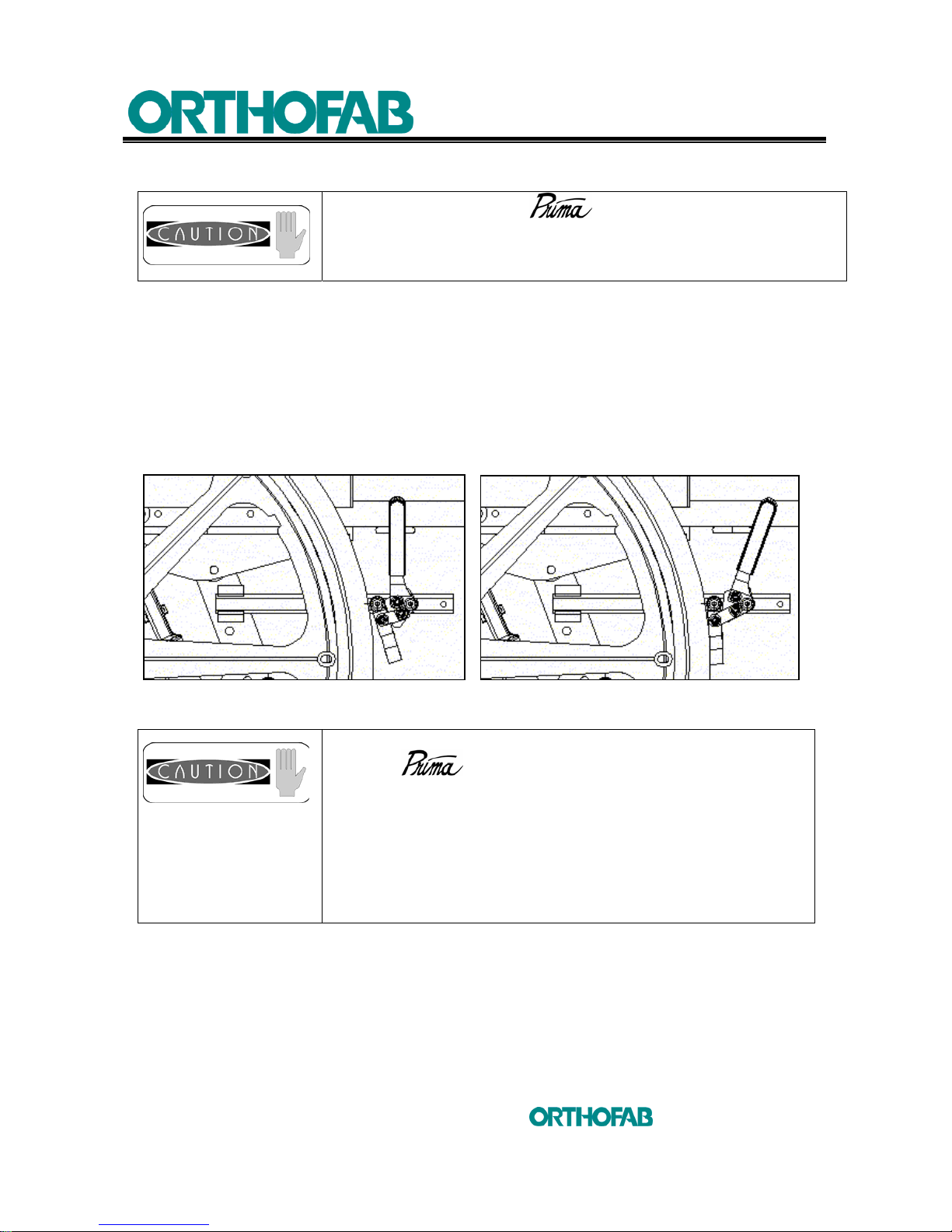
4.9.1 TO ADJUST THE POSITION OF THE PARKING BRAKE (Pushing or pulling brake type)
As per the level of wear of the tires or each time the position of the rear wheels
was changed, an adjustment of the parking brake is necessary.
a) Routine adjustment (see; figure 23) :
The effectiveness of the brake is optimum when a distance from 1/4 of an inch is
obtained between the tire and the brake (when the brakes are disengaged).
Before to adjust the parking brakes, make sure that the tire pressure is adequate;
Figure 23 : Parking brake position adjustment.
The adjustments of your wheelchair must be made by
a health care professional. Inadequate adjustments can cause
wounds and/or damage to the user, the caregiver, the
wheelchair or the environment.
It is possible to have two different type of parking brake
with the
wheelchair, by PUSHING or PULLING.
To apply the pushing brake, you have to push the brake
lever forward.
To apply the pulling brake, you have to pull the brake lever
backward.
The adjustment principle of the brake position describe at
section 4.9.1, stay the same for one or the other of these
brakes.
Page 43
4 SETUP INSTRUCTIONS
43
inc
All rights reserved
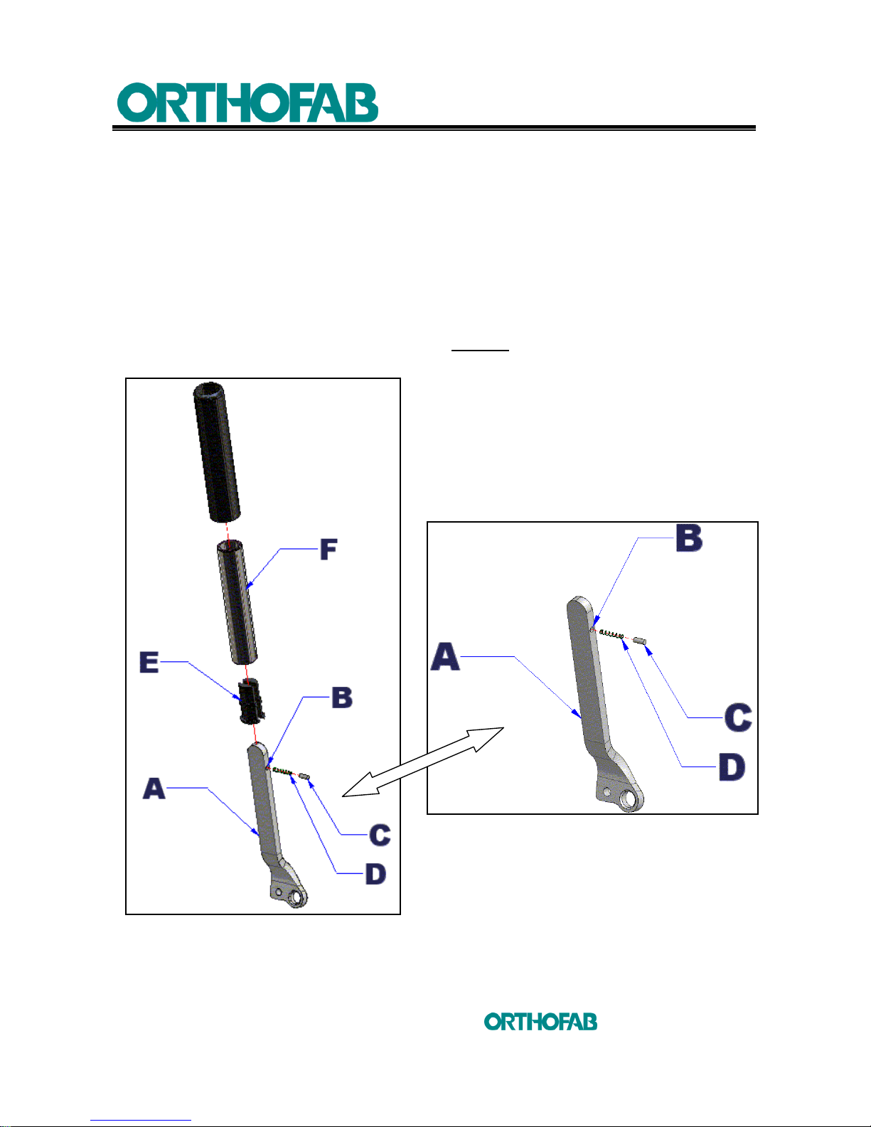
4.9.2 TO CHANGE THE BRAKE LEVERS
You have the choice of two (2) types of brake extensions that can be assembled :
a) RETRACTABLE EXTENSION (see; figure 24) :
1. Install the extension guides (E) on each side of the brake lever (A) ;
2. Place the (D) spring include with (F) extension, in the (B) hole ;
3. Insert the (C) dowel pin in the (B) hole by compressing the (D) spring ;
4. While retaining the dowel pin (C) inside the (B) hole, slide the wheel brake
extension (F) on the brake lever (A). Caution
: This assembly can be difficult to
do the first time, make sure you don't lose dowel pin (C).
Figure 24 : Retractable extension installation.
Page 44
4 SETUP INSTRUCTIONS
44
inc
All rights reserved
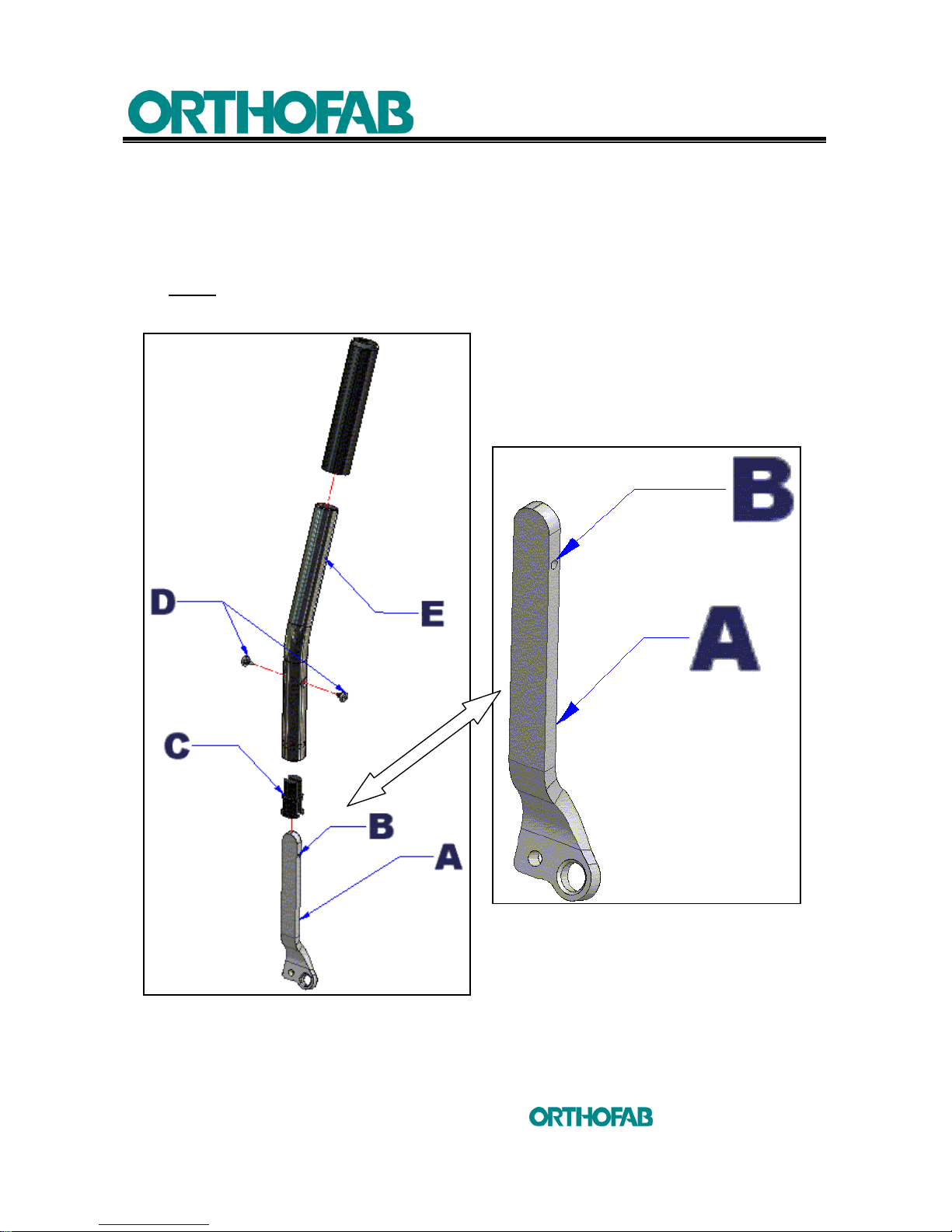
b) FIXED LENGTH EXTENSION (see; figure 25) :
1. Install the extension guides (C) on each side of the brake lever (A) ;
2. Insert the extension lever (E) on the brake lever (A) ;
3. Place the (D) screws in line with the (B) holes ;
NOTE
: If you have to drill a hole on the opposite side of the (B) hole, use a 7/64" drill.
4. Tighten (D) screws.
Figure 25 : Fixed length extension installation.
Page 45
4 SETUP INSTRUCTIONS
45
inc
All rights reserved
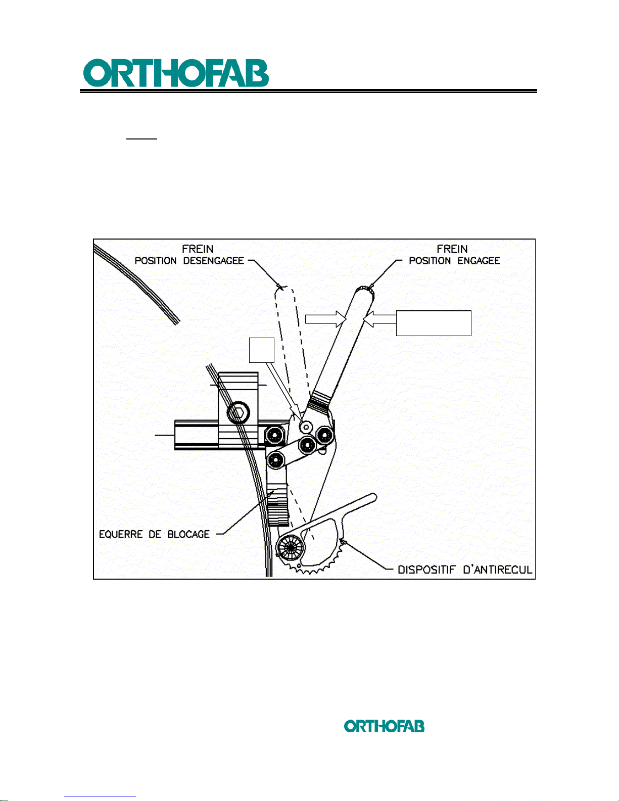
4.9.3 TO CHANGE THE ANGLE OF THE BRAKE LEVER (pushing brake type only)
NOTE
: The angle of the brake lever can be adjusted.
To do it :
• Unscrew (B) screw, using a 1/8” Allen key and carry out a rotation of the lever
until the needed position is reached ;
• Put in place (B) screw and tighten firmly.
Figure 26 : To change the angle of the brake lever.
B
LEVIER
Page 46
4 SETUP INSTRUCTIONS
46
inc
All rights reserved
4.10 ANTI-TIPPERS
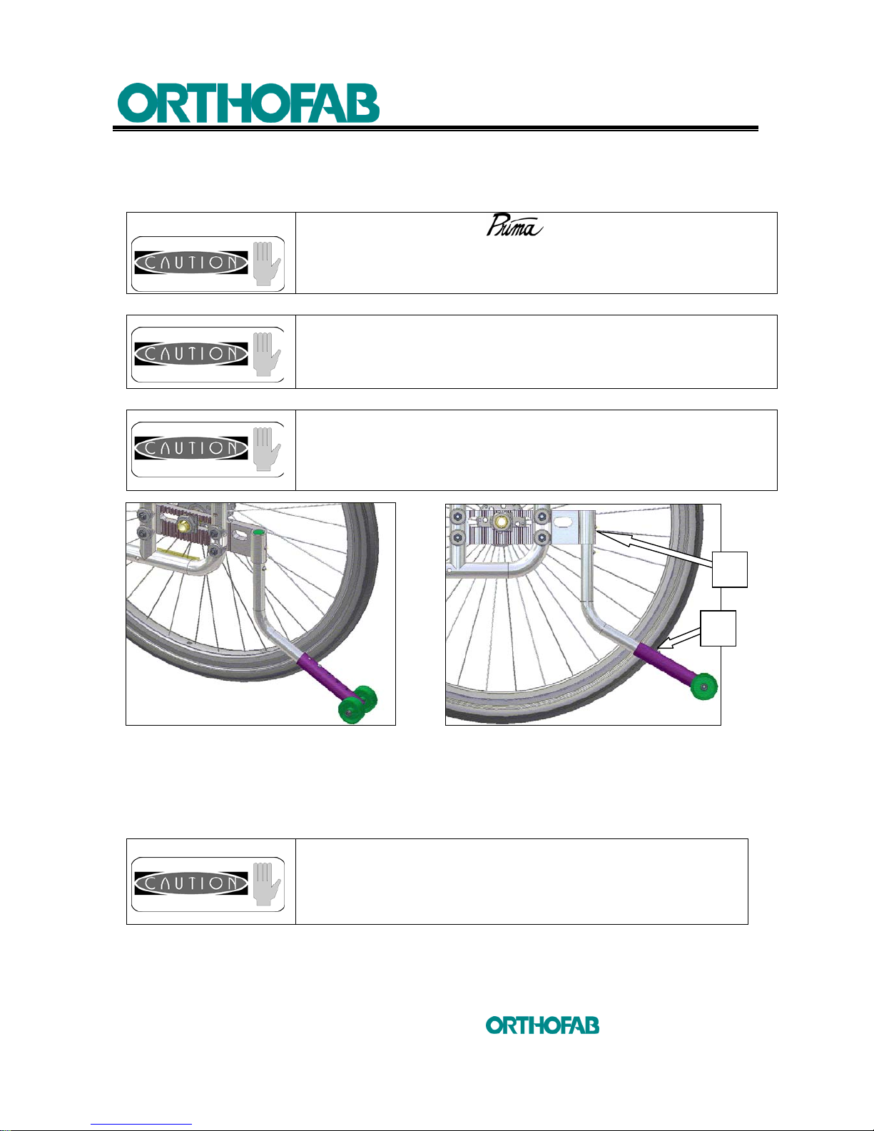
4.10.1 HEIGHT ADJUSTMENT POSITION
Figure 27-A : Anti-tippers adjustment. Figure 27-B
1. Push the (A) spring release button and slip the anti-tippers upwards or downwards to
reach the height of 1 3/4 inches relatively to the floor (see; figures 27-A and B).
2. The spring release button (B) will allow you to make a finer adjustment.
The adjustments of your wheelchair must be made by
a health care professional. Inadequate adjustments can cause
wounds and/or damage to the user, the caregiver, the
wheelchair or the environment.
A maximum of 1 3/4 inches between the floor and the antitippers must be maintained at any time.
If the seat to floor height or the dimension of the rear wheels
has been modified, the anti-tippers must be adjusted in order
to maintain the height of 1 3/4 inches between the anti-tippers
and the floor.
The anti-tippers must be secured and the spring release
button must arise from the adjustment hole.
A
B
Page 47
4 SETUP INSTRUCTIONS
47
inc
All rights reserved
4.11 ANCHOR POINTS
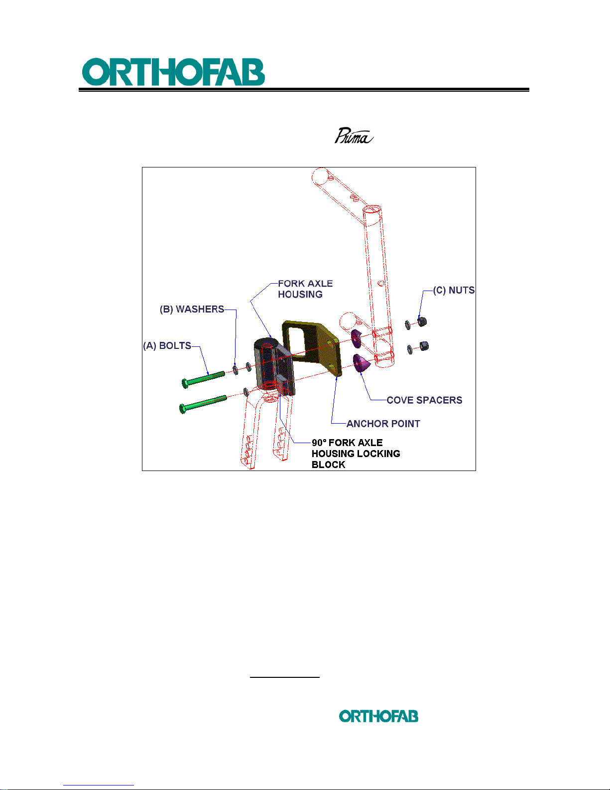
There is (2) two anchor points at the front of the wheelchair. See the figure 28
below to know how to assemble.
Figure 28 : Front anchor points assembly.
1. Unscrew and remove (A) bolts and (C) nuts, using (2) 7/16" key. Make sure to
don't lose the (B) washers and the cove spacers.
2. Place the anchor point on the cove spacers (place the cove spacers as same as
shown on figure 28), the slotted holes on the anchor point allows a depth
adjustment.
3. Place 2 new (A) bolts, the longest one lower with the 90° fork axle housing locking
block, (C) nuts and (B) washers and tighten the assembly just enough to get a little
play between parts.
4. Use a 90° square ruler. Place one side of the square on the floor (working table)
and the other one on the front face of the fork axle housing (see; section 4.7.2).
5. When the assembly will be placed at 90° angle, place the 90° fork axle housing
locking block straight and tighten firmly
all the assembly.
Page 48
4 SETUP INSTRUCTIONS
48
inc
All rights reserved
4.12 6 WHEELS CONFIGURATION
4.12.1 6 WHEELS CONFIGURATION INSTALLATION
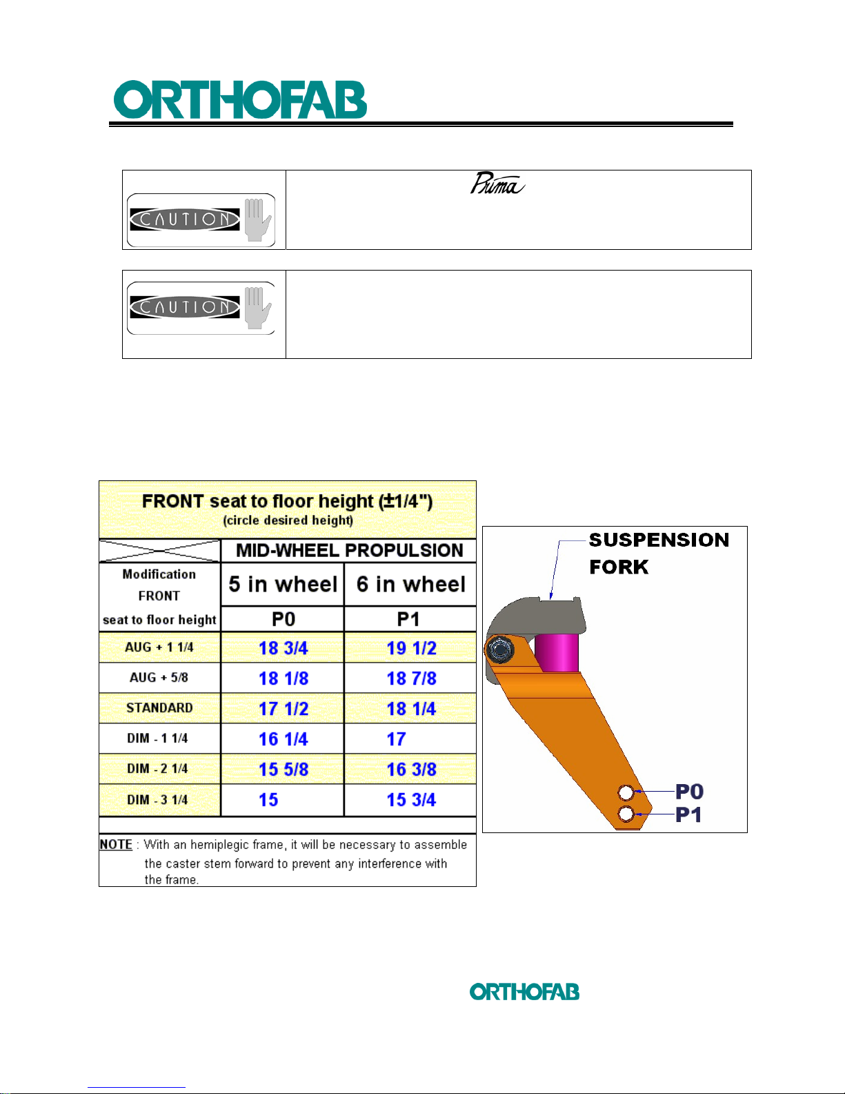
This product configuration will be in direct relation with the seat to floor height chosen. The
wheels dimensions chosen 5 or 6 inches assembled on a suspension fork in front and rear of
the wheelchair and the 2 different types of front frame will determine the seat to floor height.
There are 12 possible configurations for the 6 wheels Prima, see table 5 below.
Table 5: (Front) seat to floor height according to the chosen wheel size and frame.
The adjustments of your wheelchair must be made by
a health care professional. Inadequate adjustments can cause
wounds and/or damage to the user, the caregiver, the
wheelchair or the environment.
A maximum of ¼ of an inch between the rear wheels (which
replace the anti-tippers) and the floor must be maintained at
any time.
Page 49
4 SETUP INSTRUCTIONS
49
inc
All rights reserved
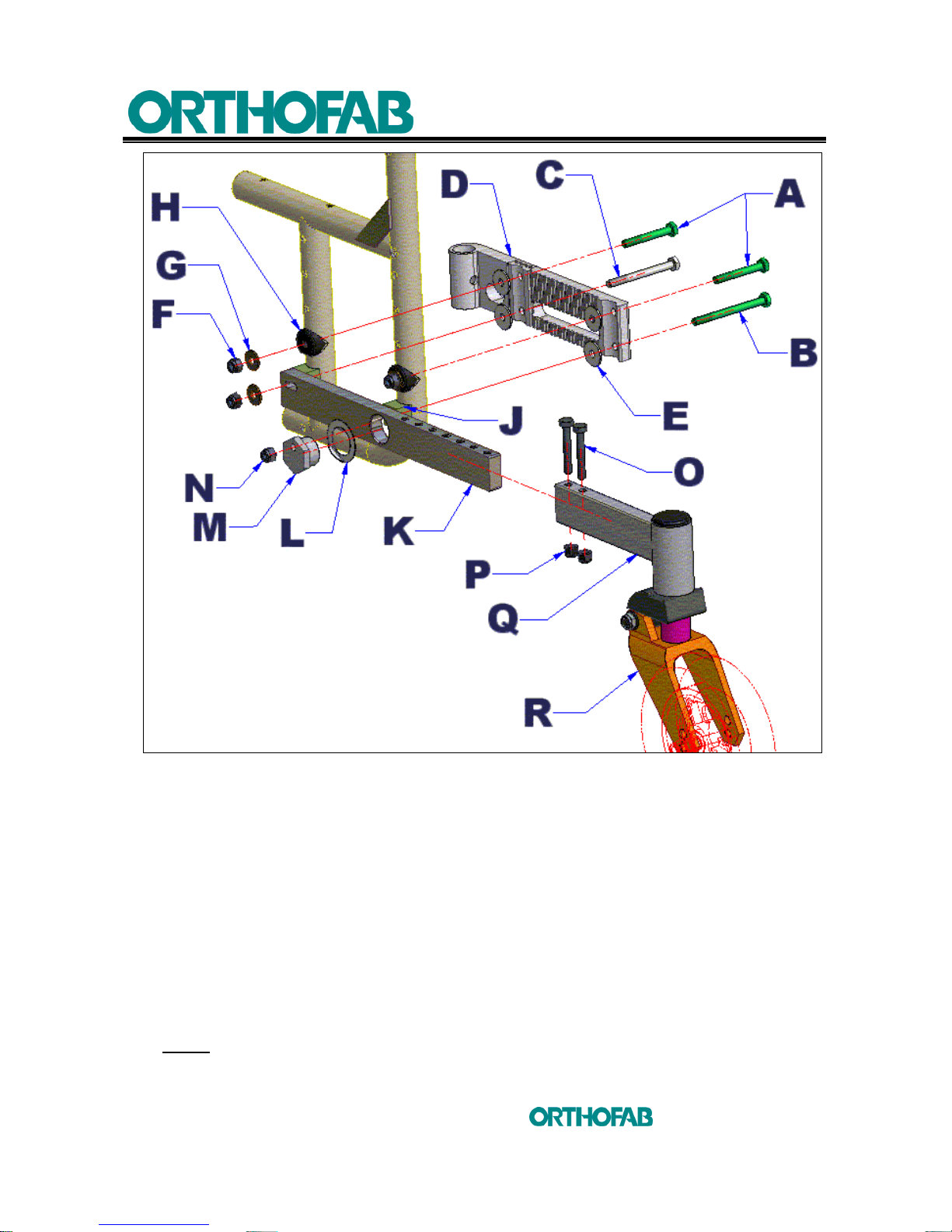
Figure 29-A : 6 wheels configuration installation.
Follow these steps for the installation of a 6 wheels configuration on the Prima wheelchair
(see; figures 29-A, B and C) :
1. Determine the front seat to floor height required, refer to the table 5 above.
2. Remove the parking brakes, they will have to be reinstalled and readjusted later.
Remove also the propulsion wheels.
3. Remove the multiposition plate (D), using (2) 7/16" key, from both side of the
wheelchair and keep the hardware, screws, washers, saddles and nuts.
4. Remove the housing (C) (see; figure 29-B and section 4.8.2) from the two
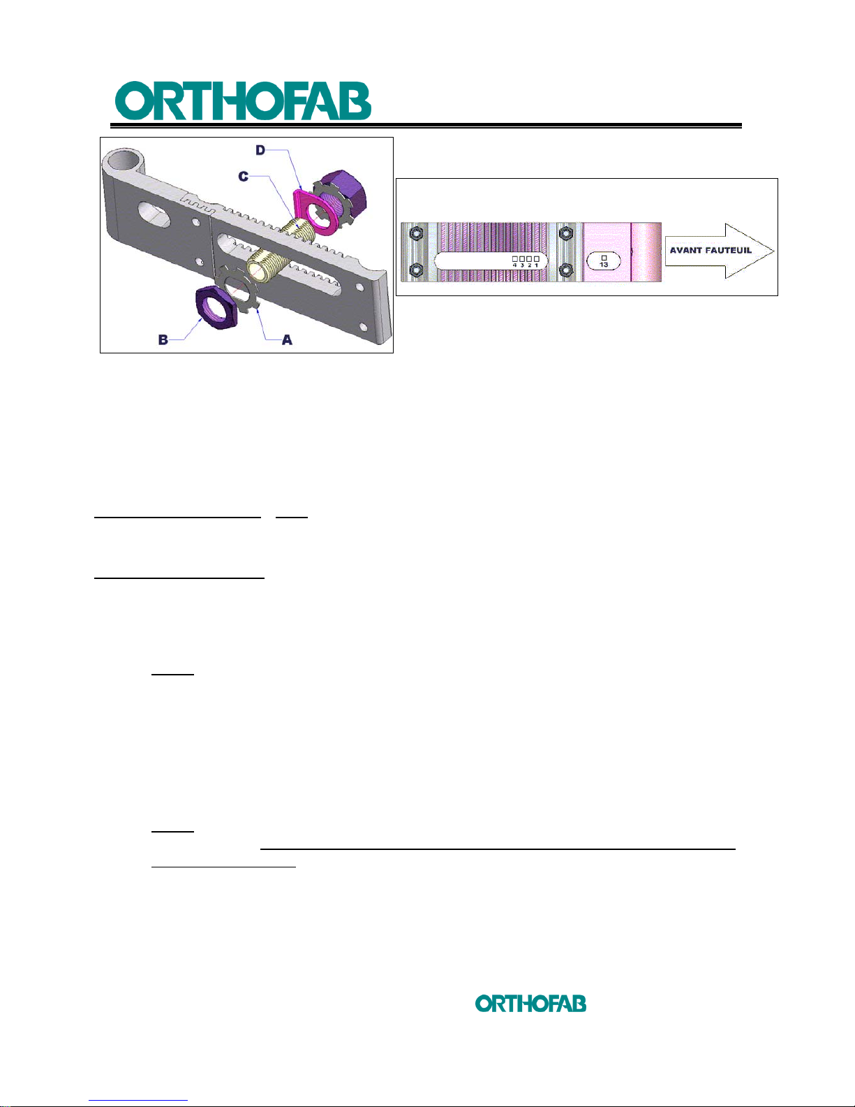
multiposition plates (D) (see; figure 29-A). For the 6 wheels configuration on a
Prima wheelchair the assembly of the (C) housing will be only possible in those 5
positions (13, 1, 2, 3 and 4) shown at figure 29-C next page.
NOTE1: At the position 13, you will not have to install the depth positioning plate (D)
(see; figure 29-B).
Page 50
4 SETUP INSTRUCTIONS
50
inc
All rights reserved
Figure 29-B : Housing (C) reinstallation on the multiposition plate.
5. Install the housings (C) at the desired position (refer to figure 29-C) on the 2
multipostion plates (D).
6. The multiposition plates (D) must be inverted for the installation on a 6 wheels
configuration. See figure 29-A to know which way the plates (D) must be installed.
7. Determine the rear seat to floor height desired (refer to table 4 at section 4.8.3)
and install the multiposition plates (D) on each side at the same height.
FOR THE UPPER FIXATION :
(NOTE: use the same hardware kept at step 3, use new (F) nuts)
Use the (A) screws, the (E) nylon washers, the (H) saddles, the (G) flat washers and
the (F) nuts.
FOR THE LOWER FIXATION :
Use the (C) screw in front and the longer (B) screw, towards rear. Put the (E) nylon
washers, the (J) saddles, the anti-tipper side frame adjustment (K), the (G) washer
and the (F) nut towards front. The (L) washer, the (M) eccentric nut and the (N) nut
towards rear.
NOTE2: The (L) washer, has a 90° bend, positioned against one of the faces of the
eccentric nut (M). Once the eccentric nut (M) will be adjusted, you will have to bend
over the (L) washer on the edge of the anti-tipper side frame adjustment (K) to prevent
the nut to turn or to loose.
8. Tighten (A) screws at a torque of 120 pounds/inch.
9. Wait before to do the final tightening of the (B) and (C) screws or to install the (Q)
fork support that should be assembled beforehand with a suspension fork (R) with
the 5 inch wheel (P0) or the 6 inch wheel (P1) following the table 5 information.
NOTE3: The (Q) fork support, should be assembled on the anti-tipper side frame
adjustment (K), at the place where it will not have any chances of interference with the
propulsion mid-wheel. There are 6 possible adjustment positions.
10. Once you will have determined the (Q) fork support position on the anti-tipper side
frame adjustment (K), tighten the (O) screws and the (P) nuts firmly.
Figure 29-C
Page 51
4 SETUP INSTRUCTIONS
51
inc
All rights reserved
11. Using a 1 1/8" key or an adjustable wrench, turn the eccentric nut (M) to adjust the
height of the rear wheels with the floor (leave a space of ¼" with the floor).
12. Once the rear wheel height will be adjusted, tighten (B) and (C) screws firmly,
using a 7/16" key and refer to the NOTE
2
of the previous page to bend over the (L)
washer using a flat screwdriver and a hammer.
13. Reinstall the parking brakes on the wheelchair as describe at section 4.9.
NOTE4 : It is likely with the 6 wheels configuration, that the pulling parking brake would
be the one to favour.
14. Check the wheelchair stability. If you are not sure of the wheelchair stability it is
better to move back the (Q) fork support on the anti-tipper side frame adjustment
(K) to get more stability.
4.13 OXYGEN CYLINDER SUPPORT
4.13.1 OXYGEN CYLINDER SUPPORT INSTALLATION
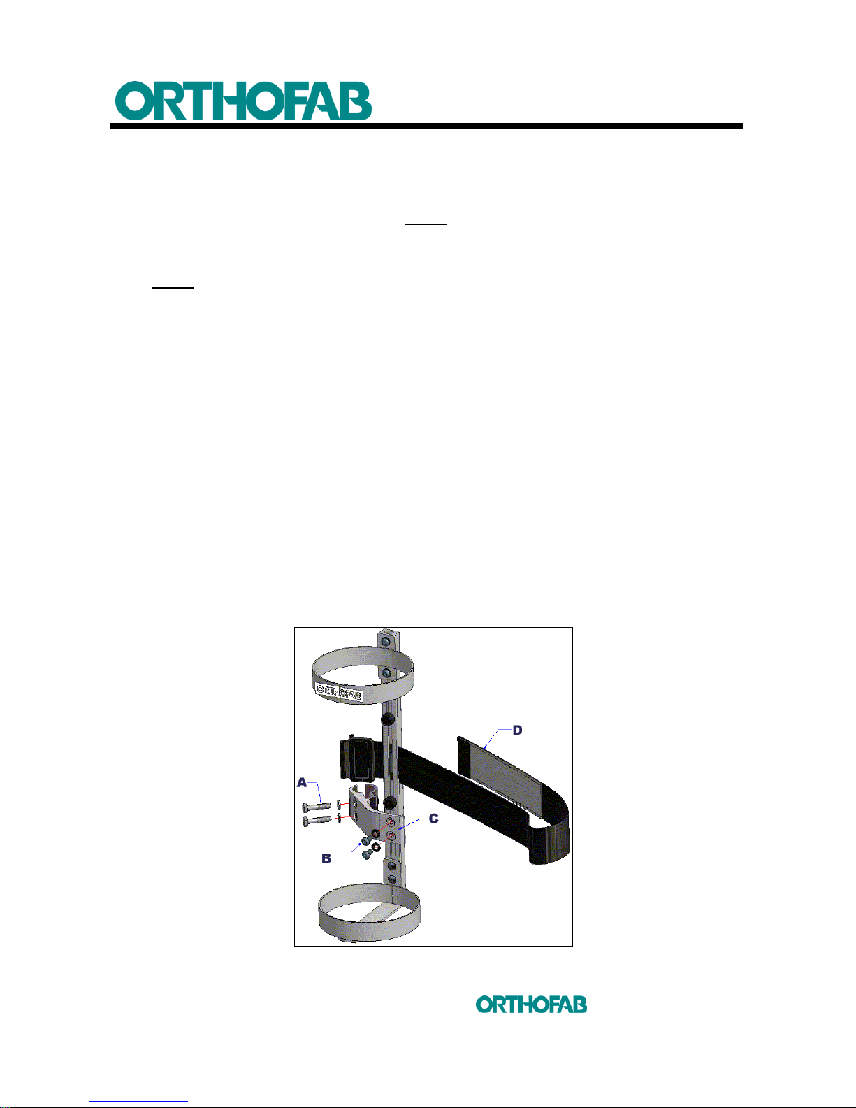
1. Determine on which side the oxygen cylinder should be installed.
2. Position the (C) mounting bracket in the way to install it on the vertical section of
the rear frame on the Prima wheelchair. If necessary, using a 5/32" Allen key,
remove the (B) screws and invert the (C) mounting bracket (see; figure 30).
3. Tighten the (A) screws of the (C) mounting bracket, using a 7/16" key, on the rear
frame of the Prima wheelchair.
4. Use the (D) strap to maintain the cylinder in place in its support.
5. Make sure to position the cylinder in the way that the valve and others cylinder
equipments do not disturb the user.
Figure 30 : Oxygen cylinder support installation.
Page 52
6 MAINTENANCE
52
inc
All rights reserved
5 OPERATING INSTRUCTIONS
5.1 HOW TO FOLD AND UNFOLD YOUR PRIMA WHEELCHAIR
5.1.1 TO UNFOLD THE WHEELCHAIR
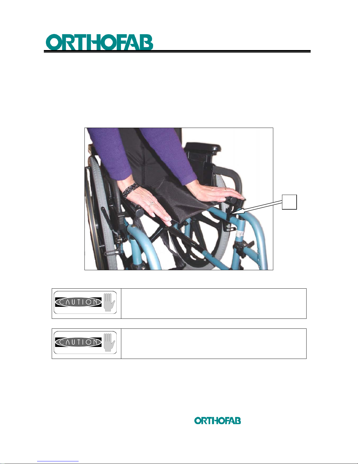
Place the wheelchair at your side; with one hand, tilt slightly the wheelchair and
with the other hand, push on the side frame until it leans on the (A) support
(see; figure 31).
Figure 31 : To unfold the wheelchair.
Make sure that the seat is completely unfolded before
seating.
When unfolding the wheelchair, avoid putting fingers
between the side frame and the frame itself.
A
Page 53
6 MAINTENANCE
53
inc
All rights reserved
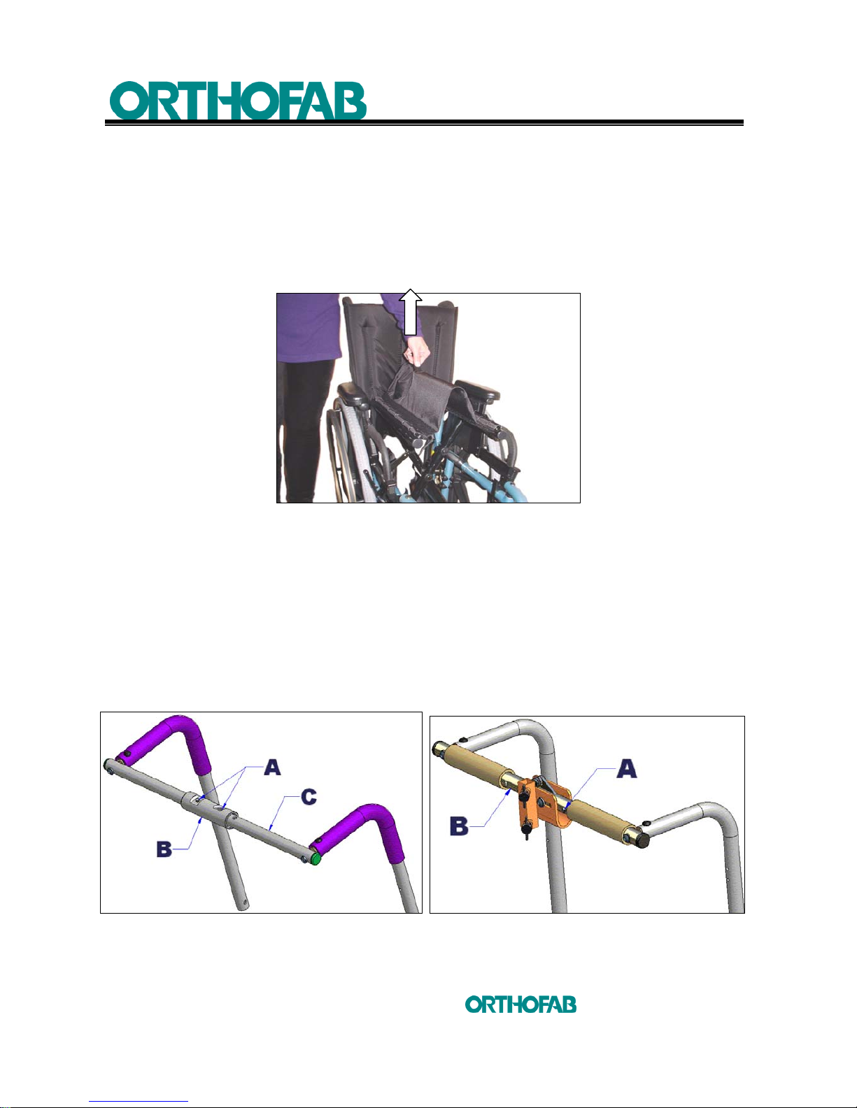
5.1.2 TO FOLD THE WHEELCHAIR
1. First, push the heel straps up and then, lift the footplates ;
2. Remove the cushion or the rigid seat ;
3. Swingaway the calf pads ;
4. Fold the backrest push handle ;
5. Grab the strap on the sling seat and pull up until the wheelchair is completely
closed (see; figure 32).
Figure 32 : To fold the wheelchair.
5.2 BACKREST PUSH HANDLE AND HEADREST ANCHOR
To fold the wheelchair :
5.2.1 BACKREST PUSH HANDLE
Push on the 2 pins (A) turn and slide the lock cylinder (B) along the tubing (C)
(see; figure 33-A).
5.2.2 BACKREST PUSH HANDLE WITH HEADREST ANCHOR
Push on the 2 pins (A) and push downward the (B) tension bar (see; figure 33-B).
Figure 33-A : Push handle. Figure 33-B : With headrest anchor.
Page 54
6 MAINTENANCE
54
inc
All rights reserved
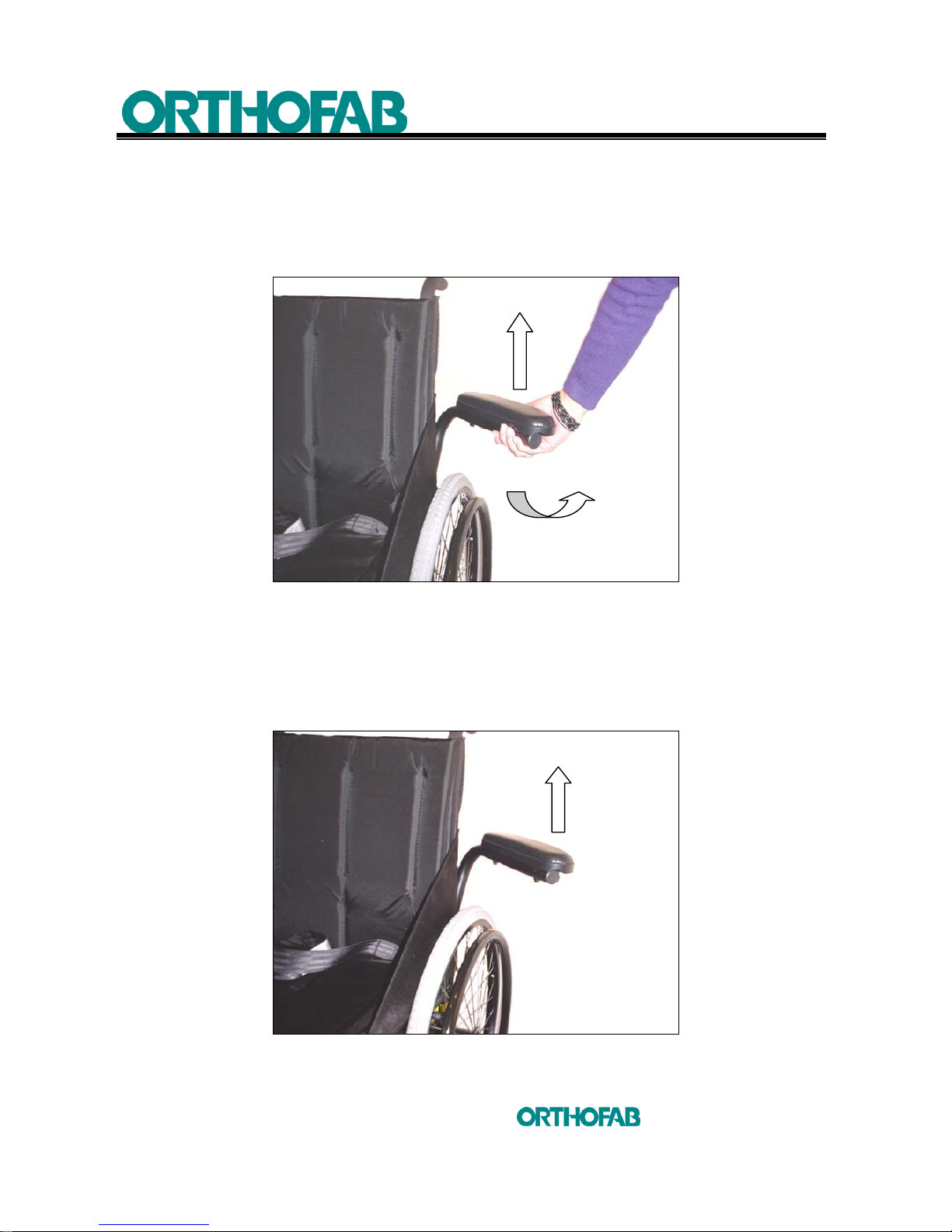
5.3 SWINGAWAY, REMOVABLE ARMRESTS
5.3.1 TO SWINGAWAY THE ARMREST
To swingaway the armrest, raise slightly the armrest while grabbing under the
arm pad and swingaway towards rear (see; figure 34-A).
Figure 34-A : To swingaway the armrest.
5.3.2 REMOVE AND/OR REPLACE THE ARMREST
• To remove it completely, raise after having swingaway towards rear.
• To replace the armrest, insert the armrest tubing in the rear receptacle and
swingaway the armrest towards front of the wheelchair (see; figure 34-B).
Figure 34-B : Remove and replace the armrest.
Page 55
6 MAINTENANCE
55
inc
All rights reserved
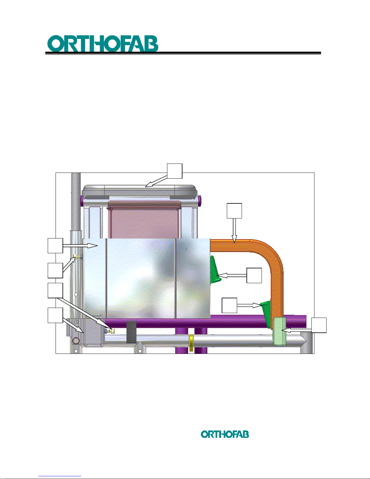
5.4 FLIP-UP, REMOVABLE ARMRESTS
5.4.1 TO SWINGAWAY
1. To swingaway the armrest, push on the (A) release button in the same direction
than the arrow and pull upwards the (E) transfer handle (see; figure 35).
2. To position the armrest in driving mode, insert the (E) transfer handle in the (B)
front socket armrest support and push down the armrest.
3. When the armrest is back into position, make sure that it is locked correctly in the
(B) front socket armrest support. Try to lift the armrest by the (E) transfer handle,
it should not move.
Figure 35 : Adjustable "U" shape armrest height.
B
A
D
E
F
G
C
H
J
Page 56

6 MAINTENANCE
56
inc
All rights reserved
5.4.2 TO REMOVE AND/OR INSTALL
1. Follow the 5.4.1 section to swingaway the armrest from its (B) front socket
armrest support (see; figure 35).
2. Unscrew slightly the locking nut and the screw (G) from the (C) rear armrest
socket, using a 8 mm key and a 4mm Allen key. Pull upwards the armrest,
grabbing it by the (J) armrest upholstery to remove it completely from the (C) rear
armrest socket.
3. To replace the armrest, first insert the rear part of the armrest in the (C) rear
armrest socket.
4. Tighten the locking screw and nut (G) and position the armrest as describe in the
5.4.1 section above.
5. After you put back in place the armrest, make sure that it is locked correctly and
secure in the (B) front socket armrest support by trying to swingaway the armrest
using the (E) transfer handle.
5.4.3 HEIGHT ADJUSTMENT
The
armrest allows a height adjustment by increment of 1 inch.
To do it (see; figure 35):
1. Unscrew slightly the locking nut and the screw (H) from the (F) armrest lateral
panel, using a 8 mm key and a 4 mm Allen key.
2. Push on the (D) release button in the same direction than the arrow and pull
upwards the armrest by grabbing the (J) armrest upholstery. Adjust the armrest
height as needed. At every step of adjustment you should feel the (D) release
button locking the armrest height in position. This will happen each time you will
reach a new position.
3. Tighten the locking screw and nut (H) to fix permanently the armrest position.
It can be dangerous to raise the wheelchair, while holding it by
the armrests.
Page 57
6 MAINTENANCE
57
inc
All rights reserved
5.5 FOOTRESTS
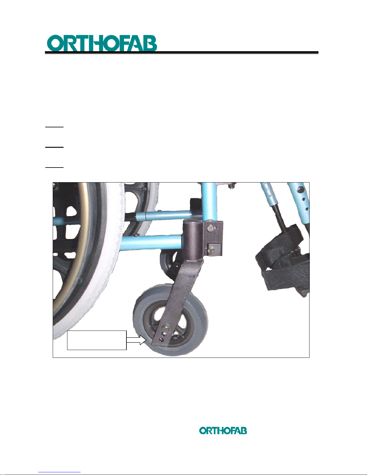
5.5.1 TO SWINGAWAY
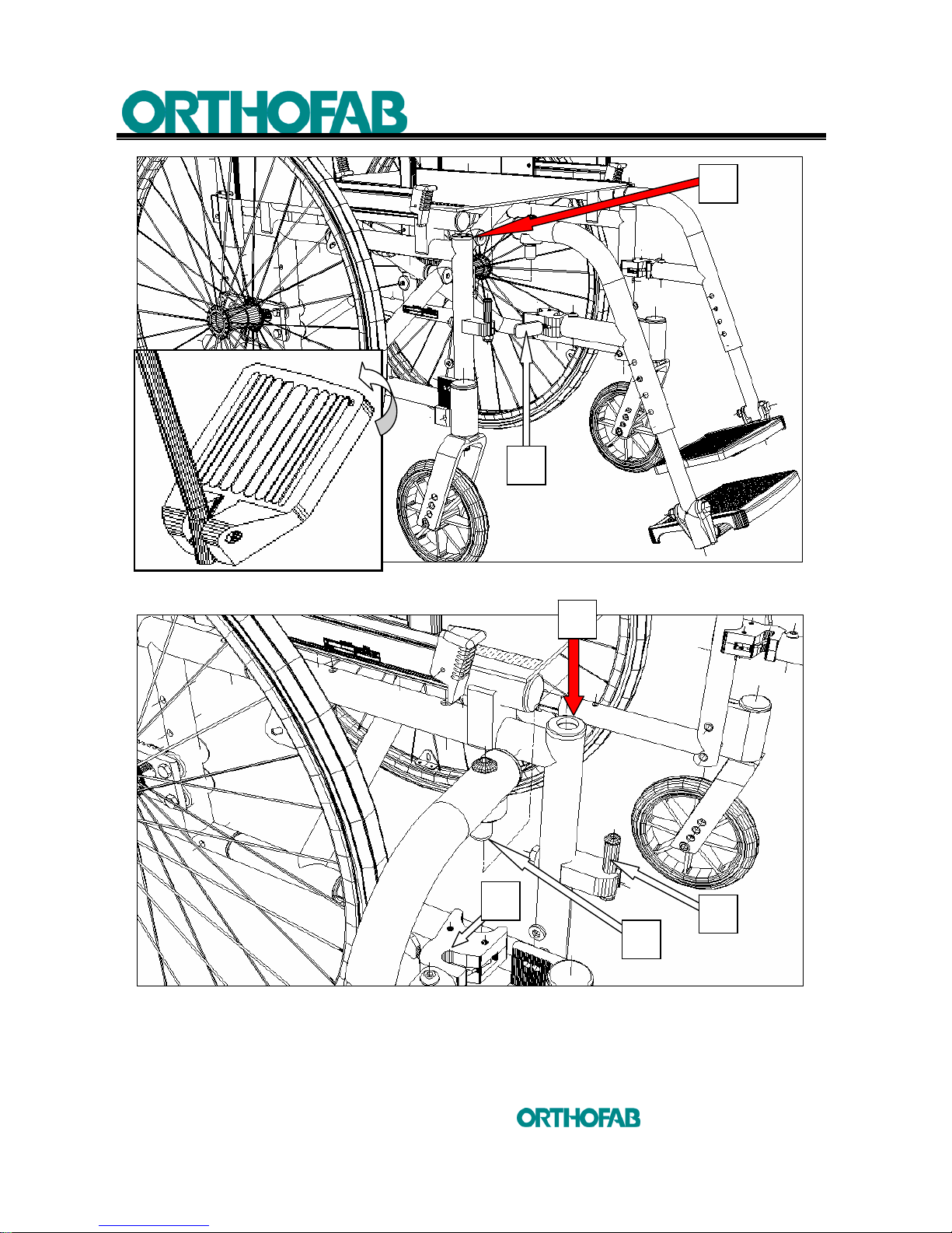
1. To remove the footrests, you will first have to take your feet off the footplates ;
2. Then by pushing on the (A) lever, the footrest will swingaway itself
(see; figures 36-B and C).
NOTE1 : It is preferable to fold back the footplate before to swingaway the footrest
(see; figure 36-B).
NOTE2 : In some cases, because of the front casters position, it can be difficult to
swingaway completely the footrest.
NOTE3 : Always check that the front casters are in forward driving position
(see; figure 36-A).
Figure 36-A : To swingaway the footrest, front wheels in forward driving position.
FORWARD
DRIVING POSITION
Page 58
6 MAINTENANCE
58
inc
All rights reserved
Figure 36-B : To swingaway the footrest.
Figure 36-C : To swingaway the footrest.
A
FOLD BACK
THE FOOTPLATE
B
C
C
D
E
Page 59
6 MAINTENANCE
59
inc
All rights reserved
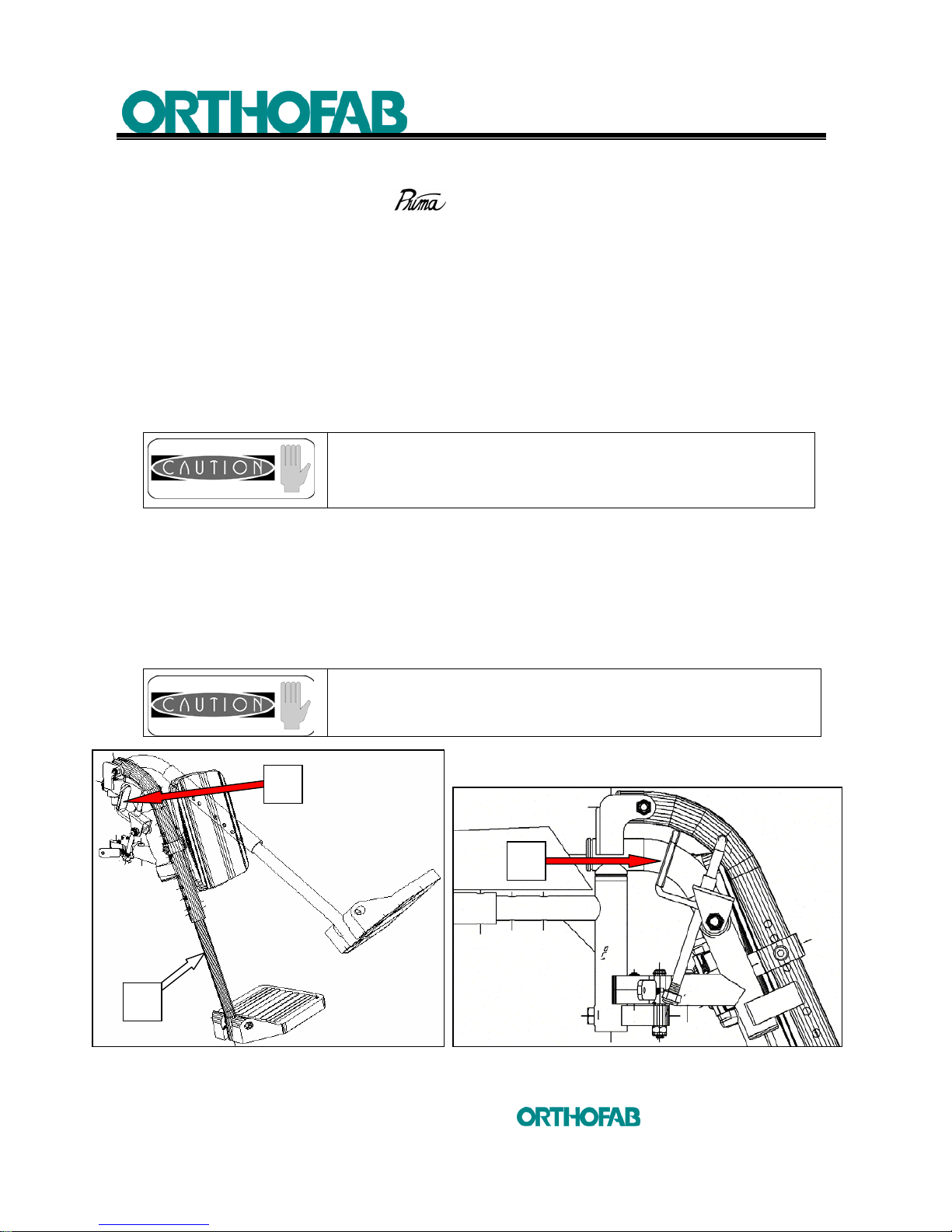
5.5.2 TO REMOVE AND/OR INSTALL THE FOOTREST
• All the footrests on the
wheelchair are removable ;
1. To do this, it is initially necessary to swingaway the footrest as described earlier
in section 5.5.1;
2. Then grab the legrest by its upper part, and raise it to release from the (C)
hanger bracket (see; figures 36-B and C);
3. To replace the footrest, it is necessary to orient it at a 90° direction relatively to
the seat and insert the footrest guide (B) in the (C) hanger bracket
(see; figure 36-C);
4. Then, you will be able to swingaway the legrest to lock it in its original position.
The blocking mechanism (D) must lock on the locking pin (E).
It can be dangerous to raise the wheelchair, while holding
it by the footrests.
5.5.3 TO RAISE AND LOWER THE LEGREST
a) To raise the legrests, it might be necessary to remove your foot from the footplate
and your legs from the calf pads; then grab the telescopic tubing and pull upwards.
The legrest will block itself in the needed position (see; figure 37-A).
b) To lower, push on the (B) lever while grabbing the telescopic tubing. You will
then be able to lower the legrest (see; figures 37-A and B).
Never put your fingers in the mechanisms when you
proceed to either raise or lower the legrest. To raise or
lower, always handle it by grabbing the telescopic tubing.
Figure 37-A : To raise and lower the legrest. Figure 37-B
B
B
A
Page 60
6 MAINTENANCE
60
inc
All rights reserved
5.6 TENSION ADJUSTABLE BACKREST
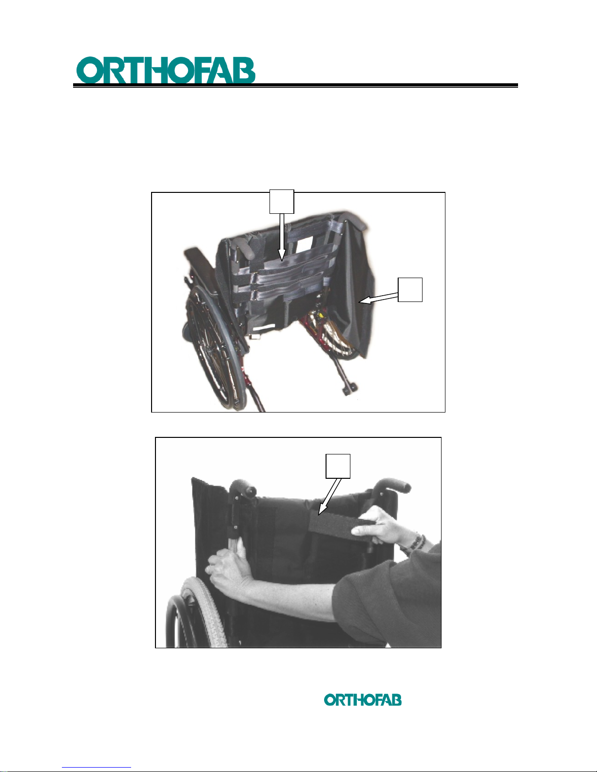
The tension adjustable backrest is composed of a series of "Velcro" straps (A) allowing
tension level adjustment. To adjust your backrest, open the rear flap (B), adjust each
straps to the needed tension. When closing the flap, make sure that the straps are well
secured. The central straps (C) can also be adjusted in height.
(see; figures 38-A and B).
Figure 38-A : Tension adjustable backrest open.
Figure 38-B : Tension adjustable backrest adjustment.
A
B
C
Page 61
6 MAINTENANCE
61
inc
All rights reserved
5.7 REAR WHEELS
5.7.1 TO INSTALL AND/OR TO REMOVE
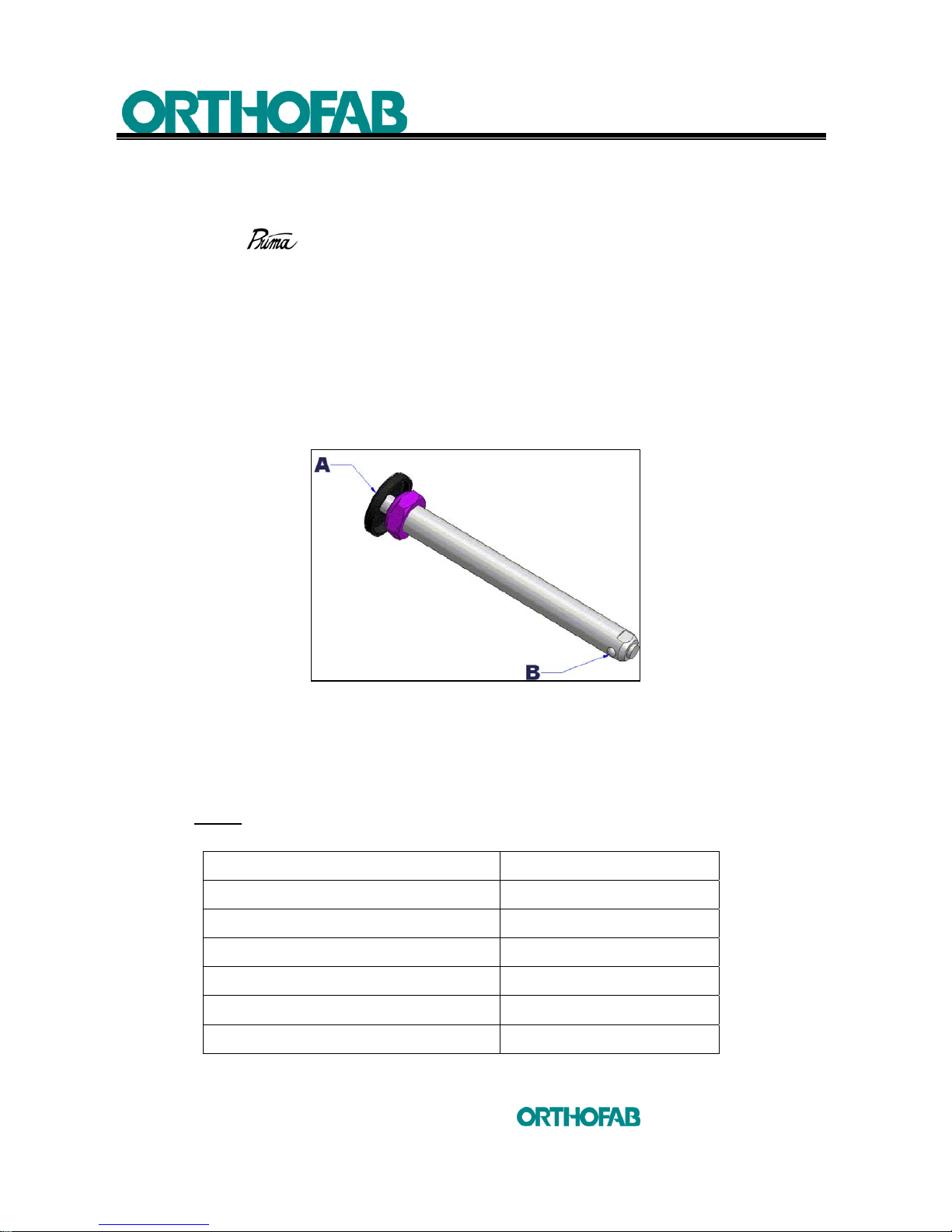
If your
is equipped with a quick release axle, you can remove the wheels
in order to facilitate transportation of the wheelchair.
This operation is carried out when nobody is seated in the wheelchair.
To remove the wheel :
1. Push the (A) button and pull the wheel towards you. Handle the wheel from
its center part (see; figure 39) ;
2. To install, push t he (A) button and insert the axle in the housing. Make sure
that the axle is locked in place in the housing by the blocking pins (B).
Figure 39 : Quick release axle.
5.7.2 PNEUMATIC TIRE PRESSURE
In order to guarantee optimum performances from your wheelchair, the tire
pressure must be checked every week.
NOTE : Make sure that the inflating apparatus will not damage the tire, if a
higher pressure than the one supported by the tire can be reached.
Caster 6 x 1 ¼ inches 35 psi
Caster 7 x 1 ¾ inches 35 psi
Caster 8 x 1 ¼ inches 35 psi
Caster 8 x 2 inches 35 psi
Rear wheel 20 inches 65 psi
Rear wheel 22 inches 65 psi
Rear wheel 24 inches 65 psi
Page 62
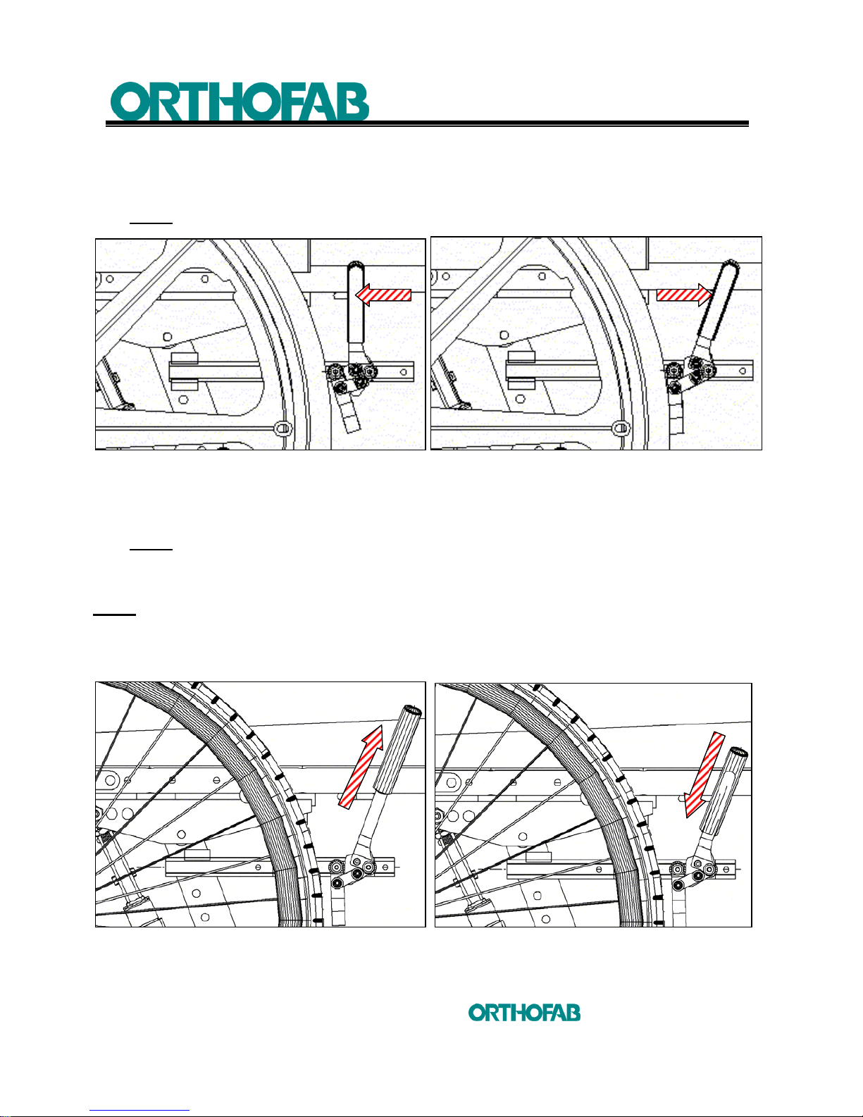
6 MAINTENANCE
62
inc
All rights reserved
5.8 PARKING BRAKES
5.8.1 TO APPLY AND DISENGAGE THE PARKING BRAKE the PUSHING type
NOTE : With the PULLING brake type, invert the lever action.
Figure 40-A : Brake disengage.
Figure 40-B : Brake apply.
a) To apply the brake, exert a pressure on the handle towards front (see; figure 40-B) ;
b) To disengage the brake, pull the handle towards you (see; figure 40-A).
NOTE : If the tire pressure is inadequate, the effectiveness of the brake is uncertain.
5.8.2 RETRACTABLE HANDLES
NOTE : In order to facilitate accessibility, the brake can be equipped with a retractable extension.
a) To use this extension, pull on the handle upwards (see; figure 41-A) ;
b) Push back to retract (see; figure 41-B).
Figure 41-A : Retractable handle in extension. Figure 41-B : Retracted.
Page 63
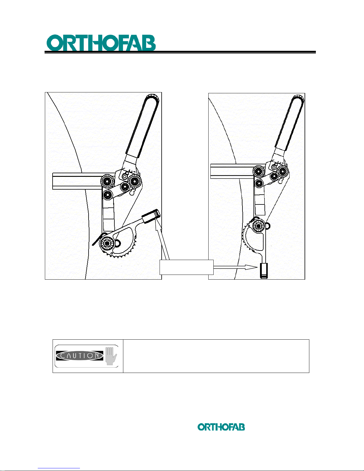
6 MAINTENANCE
63
inc
All rights reserved
5.8.3 APPLY – DISENGAGE THE HILL HOLDER
In order to be able to climb slopes, your wheelchair can be equipped with a hill holder
mechanism to stop backward movement when climbing.
Figure 42-A : Hill holder disengage. Figure 42-B : Hill holder apply.
1. To put the hill holder in function, lower the lever towards the ground
(see; figure 42-B);
2. To disengage the hill holder, pull the lever upwards. The wheelchair is now free
to move backward (see; figure 42-A).
When driving the wheelchair, hold your fingers distant
from this mechanism.
LEVER
Page 64
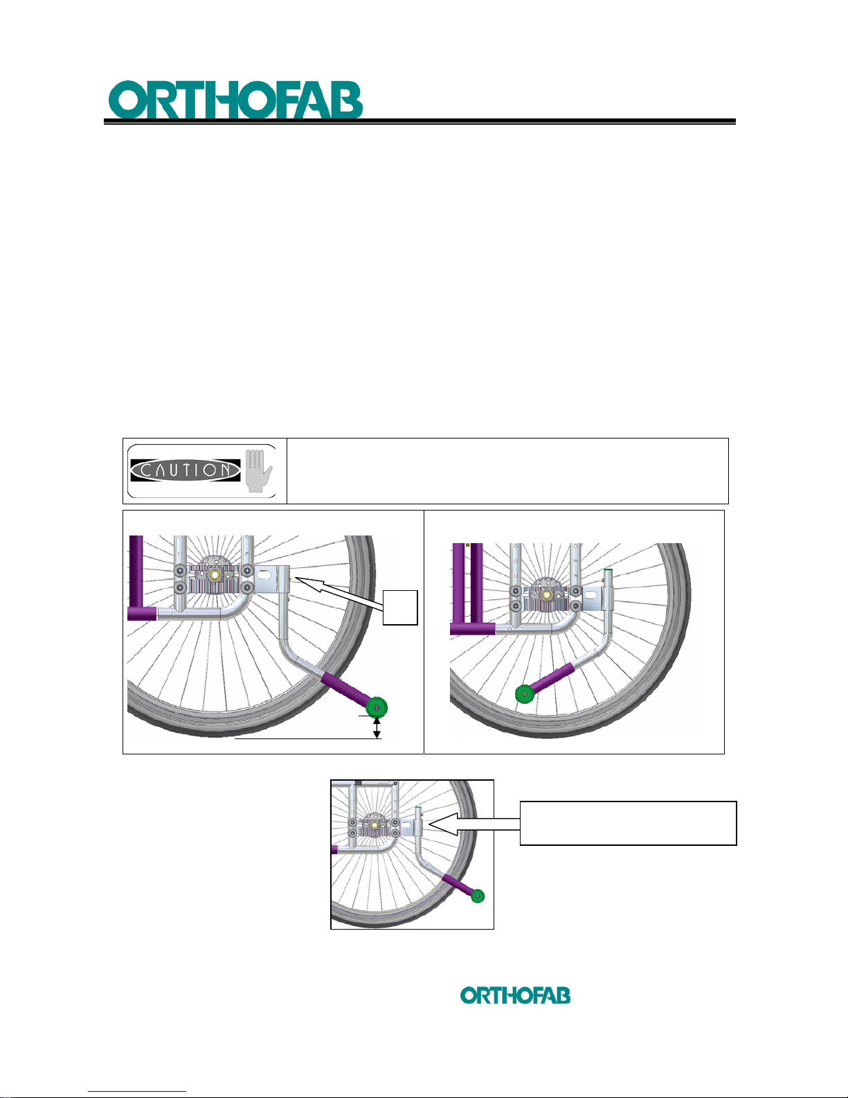
6 MAINTENANCE
64
inc
All rights reserved
5.9 ANTI-TIPPERS
5.9.1 TO REMOVE AND/OR RETRACT
• In order to facilitate the transport of your wheelchair, the anti-tippers can
be removed. To do this, exert a pressure on the spring button (A) and
remove the anti-tipper from its housing (see; figure 43-A).
• An other possibility is to press the (A) spring button and to retract the
anti-tipper under the seat, until it reach the opposite hole of the housing
(see; figure 43-B).
5.9.2 TO RETRACT
• To go over some obstacles, the anti-tippers can be ret racted upwards or
completely under the seat (see; figure 43-B) ;
• In this case, a third person must protec t your displacements from behind
the backrest, both hands in contact with the backrest push handles.
Never use your wheelchair if the anti-tippers are not in
propulsion position.
PROPULSION POSITION
RETRACTED POSITION
Figure 43-A : Anti-tippers. Figure 43-B
1 3/4"
A
ANTI-TIPPERS POSITION TO GO
OVER SOME OBSTACLES
Page 65
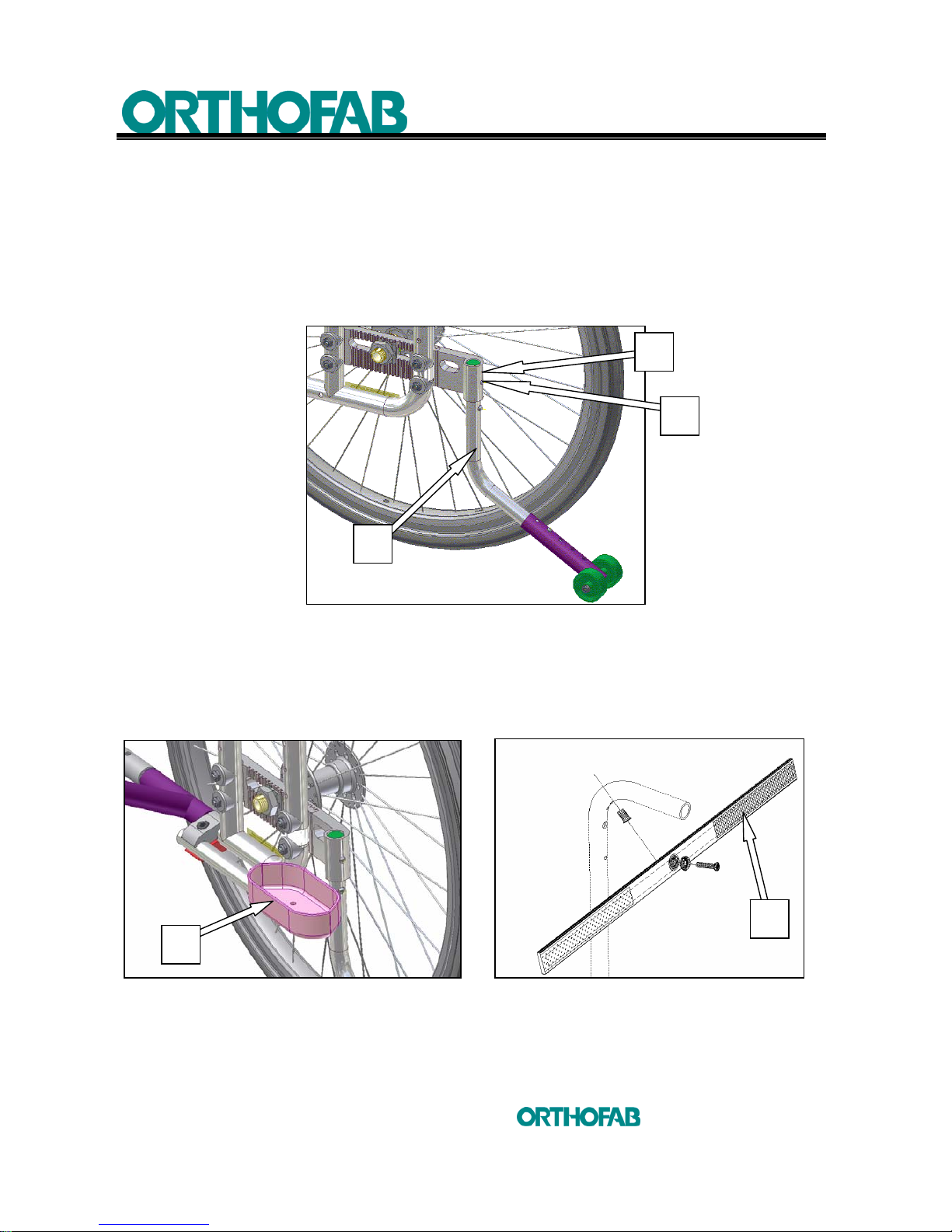
6 MAINTENANCE
65
inc
All rights reserved
5.9.3 TO REPLACE
• To replace the anti-tippers, insert the (B) tubing in its (C) housing while pushing
slightly the (A) spring release button. When the spring button will catch itself in
the hole, this will indicates that the anti-tippers are secured ;
• Make s ure that the anti-tippers are correctly locked in their housing. Try to turn or
remove them from their (C) housing (see; figure 44).
Figure 44 : Replace the anti-tippers.
5.10 CANE AND CRUTCH HOLDER
Install canes and crutches in the (A) support and fasten (cane or crutch) near the push
handle using the (B) "Velcro" strap. (see; figures 45-A and B).
Figure 45-A : Cane and crutch holder. Figure 45-B : “Velcro” strap.
C
B
A
A
B
Page 66
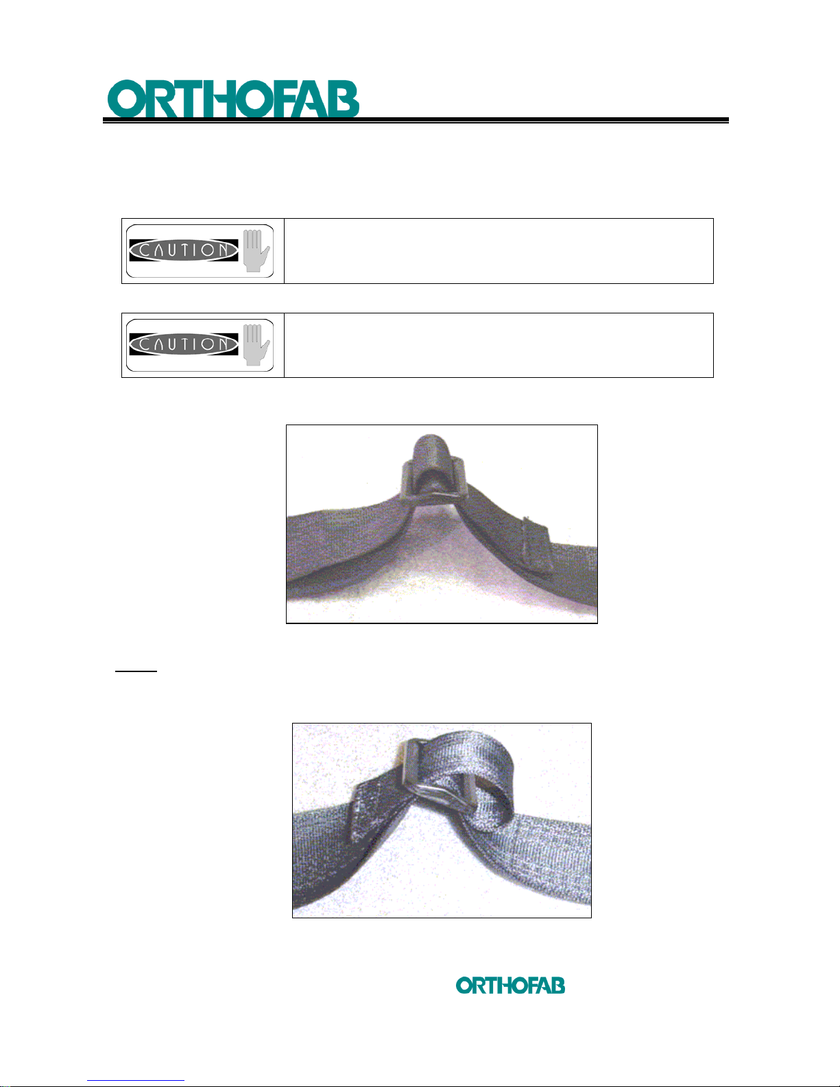
6 MAINTENANCE
66
inc
All rights reserved
5.11 SEAT BELT
It is important for your comfort and safety that the belt provided with the wheelchair be
adjusted to your size.
Never modify the assembly or anchor point of your belt.
In a paratransit transportation, the belt provided with your
wheelchair, cannot be used as a seat belt.
To adjust the belt length, slip the strap in the plastic loop as represented at figure 46-A.
Figure 46-A : Seat belt length adjustment.
NOTE: The free part must always exceed at least three (3) inches from the plastic loop.
If you want to prevent the strap to slip from the plastic loop, pass the belt again in the
plastic loop as shown at figure 46-B.
Figure 46-B : To prevent seat belt strap to slip from the plastic loop.
Page 67
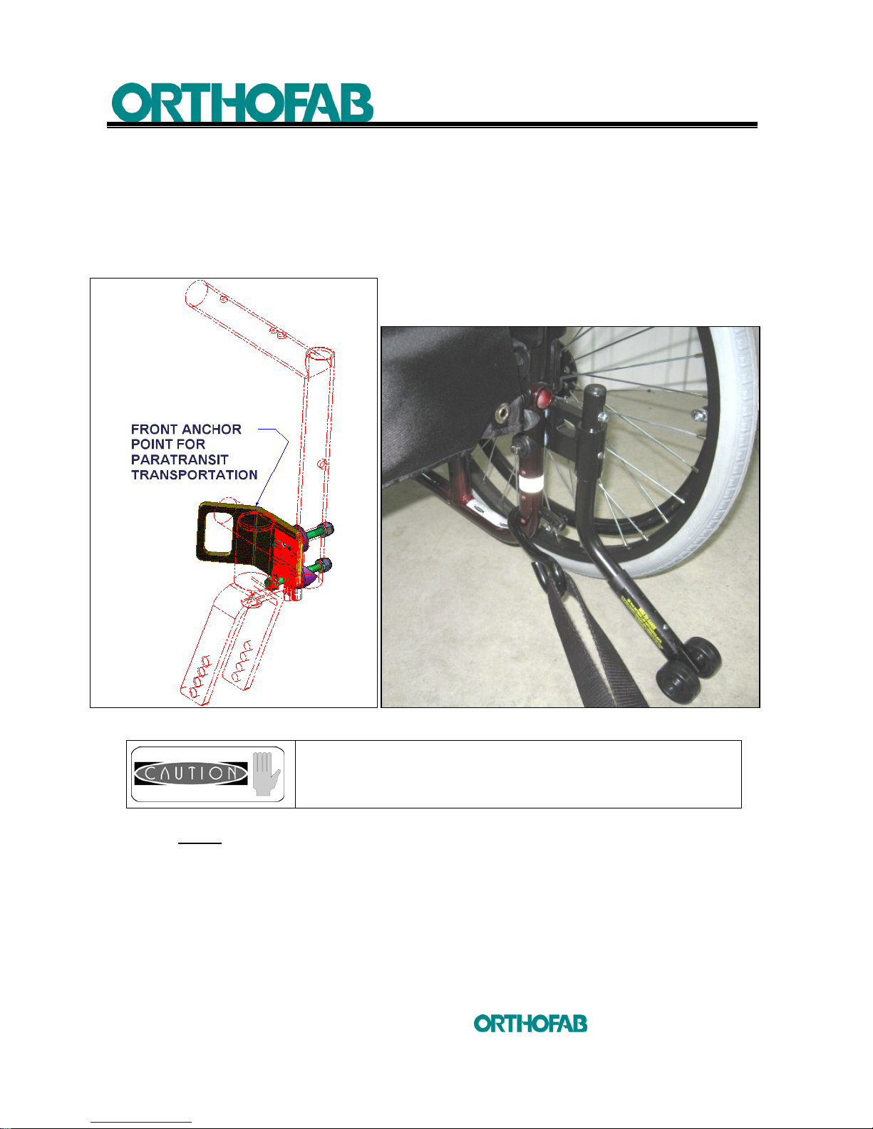
6 MAINTENANCE
67
inc
All rights reserved
5.12 TRANSPORTATION
5.12.1 ANCHOR POINTS LOCALIZATION
In order to immobilize your wheelchair during transportation, your wheelchair is
equipped with four (4) anchor points. Two (2) are placed at the front and two (2) at the
rear. The front anchor points are located right beside the fork support (see; figure 47-A).
Figure 47-A : Front anchor point. Figure 47-B : Rear anchor point.
Always use these anchor points in a paratransit
transportation.
NOTE
: If you remain seated in your wheelchair during transportation, it will be
necessary to use a seat belt independent of your wheelchair. This one will
generally be of the same type as those used in automobile vehicles.
The rear anchor points are located on the rear frame vertical part of the
wheelchair. Insert the hook as shown at figure 47-B.
Page 68

6 MAINTENANCE
68
inc
All rights reserved
5.12.2 ADVICE FOR TRANSPORTATION
• Check that the brakes immobilize your wheelchair completely ;
• Put your seat belt and make sure that it is well adjusted to your size.
• Lower the legrest ;
• Always use your seat belt (restraint belt);
•
does not assume any responsibility as for the risks incurred by the
use of the wheelchair as a seat in a public transport vehicle.
• Your wheelchair is equipped with anchor points in the event of transportation.
These anchor points cannot replace the approved restraint systems (seat belt)
from Transport Canada;
• Do not raise the wheelchair by its detachable components (armrests, footrests,
etc...).
Page 69

6 MAINTENANCE
69
inc
All rights reserved
6 MAINTENANCE
MAINTENANCE PROCEDURE
To function adequately and in a safe way, your wheelchair, like any other vehicle,
needs care. A routine maintenance will increase the lifespan and the
effectiveness of your wheelchair.
Once a year, bring your wheelchair at a qualified retailer or an authorized service
center for an in-depth inspection and maintenance. A regular cleaning will reveal
parts requiring adjustment or worn out.
Check list
Initial adjustments must be made according to your personal needs. For any
subsequent maintenance, follow these procedures:
At delivery
Weekly
Monthly
Periodically
1. General
The wheelchair drives in a straight line, it does not draw on one side.
x x
2. Brakes
Must not interfere with the wheels when you drive, engage and disengage
themselves easily. The mobile parts are neither loose, nor worn.
x x
3. Cloth guard
Check for deformation or protuberant parts, make sure that all the fasteners
are secured.
x x
4. Armrests
Solid but easy to remove
x x
5. Armrest pad
Check for tear – Make sure that the armrest pad is correctly fastened to the
armrest.
x x
6. Fabrics of seat and backrest
Check for tear or depression.
x
7. Cable and release handle
The cables do release completely and return to their original position after
released.
x x
8. Rear wheels 20, 22 and 24 inches
Make sure that the wheel bearings are in good condition and that the wheels
are free of movement.
x x x
9. Hand rims
Check for rough finish or peels. Make sure that they are correctly
assembled to the wheels.
x x
10. Front casters
Make sure that the tension is adequate while swiveling the wheel, it should
stop gradually. Adjusts the tension on the bearing if the wheel stops
abruptly.
CAUTION The tires must be checked periodically for signs of wear and
tear and be replaced, if necessary.
x x
11. Tires
Check for wear. If pneumatic, check the air pressure.
x x
12. Axles
Keep the axles clean and oiled (3 in 1 oil)
x
13. Cleaning
Clean and wax all parts -
x
Page 70

6 MAINTENANCE
70
inc
All rights reserved
Tire pressure
Usually, recommended air pressure will be written on the side of the tire. However,
if absent, you can refer in the following table.
6 x 1 ¼ Tire 35 psi
7 x 1 ¾ Tire 35 psi
8 x 1 ¼ Tire 35 psi
8 x 2 Tire 35 psi
20 inches Tire 65 psi
22 inches Tire 65 psi
24 inches Tire 65 psi
After having carried out an adjustment, make sure that all the
parts are well tightened BEFORE using the wheelchair. DO
NOT tighten too much the hardware.
Page 71

7
BREAKDOWN SERVICE GUIDE
71
inc
All rights reserved
7 BREAKDOWN SERVICE GUIDE
Wheelchair
steers right
Wheelchair
steers left
Wheelchair
is difficult to
propulse
Loose front
caster
Noise
SOLUTIONS
X X X
Check tire pressure
X X X
Check screws and nuts tightening
X X X
Make sure that both front casters
touch the ground simultaneously
Check spokes tightening
X X X X
Check the front forks angle
X X
Check the adjustment of the rear
wheel axle (equal on both side)
X X X
Check the front and the rear wheel
bearing
X X
Check the fork and caster bearings
Page 72

8 WARRANTY
72
inc
All rights reserved
8 WARRANTY
will warranty the the
manual collapsible wheelchair against any
manufacturing defect for a period of one (1) year from the delivery date. This warranty
cover the components and the wheelchair complements except for the tires, tubes and
the covering of seat, backrest and armrest of which the warranty is (1) month.
will repair or replace any defective parts that will be returned carefully
packed to prevent any further damage and send (paid port) to an authorized
service center and this, during the warranty validity period.
However, this warranty does not apply to parts and components damaged by abuse,
carelessness, accident and normal use or installed and modified by an unauthorized
person.
guarantees the availability of components and parts necessary to the
operation of the wheelchairs for a five (5) year period from the delivery date.
The present warranty is given in place of any other written, tacit or statutory warranty.
The responsibility of
is limited to repair or the replacement of any parts or
components, according to the above-mentioned terms.
Exclusions and limitations
This warranty does not apply to products, which have been the subject of carelessness,
accidental, normal use or abnormal use, maintenance or defective storage. Moreover,
this warranty does not apply to products damaged in consequences of a repair, a
component modification without the express assent of
neither with repairs
and/or modifications not carried out by an
authorized distributor and nor with
the products damaged because of circumstances independent of the will of
This warranty is limited to repairs and, with absolute discretion of
to the
replacement of defective parts as expressed with the present warranty. Except for the
warranty expressed in this document,
does not grant, relative with its
products, any warranty express or implicit, legal or conventional, including for hidden
vice, nor no implicit warranty of marketable quality or suitability aiming at a particular
use, except contrary stipulation with the present warranty.
The warranty stipulated above replaces any responsibility or obligation of
concerning the damage coming from or referring to the
products.
Page 73

8 WARRANTY
73
inc
All rights reserved
cannot, in any case, be held responsible for the particular, indirect or
consecutive damage, even if
were informed of the possibility of such
damage. The warranty of the distributor is expressly limited to the repair and the
replacement of non-conformity of products as envisaged in this warranty or to the
refunding of a sum not exceeding the purchase price of the material in question.
The stipulations above constitute the complete and exclusive warranty declaration
which applies to the
products and overrides any proposal or former
agreement, orally or written, and on any other communication in between
and a particular distributor relative to the
warranty.
does not assume any risk related to damages who could happen during
shipment.
do not grant any other warranty but that which is envisaged above. All the
warranties, including the implicit warranty of marketable quality and suitability aiming at
a particular use are limited to the period indicated above starting from the date of
purchase.
cannot be held responsible for the particular, indirect or
consecutive damage, from contractual nature, that result from an offence or another
cause.
NOTES:
• Components exchanged under this warranty will be covered by the original
warranty.
• If a component is returned to get its warranty enforced, but is considered by
as functional. The component will be returned to the customer.
Page 74

9
AUTHORIZED SERVICE CENTRES
74
inc
All rights reserved
9 AUTHORIZED SERVICE CENTRES
Institut de réadaptation en déficience physique de
Québec
(Centre Cardinal-Villeneuve)
2975, chemin Saint-Louis
Sainte Foy (Québec) G1W 1P9
Tél.: 418-529-9141
Institut de réadaptation en déficience physique de
Québec
(Centre François-Charron)
525, boulevard Hamel
Québec (Québec) G1M 2S8
Tél.: 418-529-9141
Centre de réadaptation en déficience physique
Carrefour de santé de Jonquière
2230, rue de l’Hopital CP 1200
Jonquière, QC, G7X 7X2
(418) 695-7787
Hôpital Sainte-Justine 3175, côte Sainte-Catherine
Montréal (Québec) H3T 1C5
Tél.: 514-345-4931
Institut de réadaptation de Montréal 6300, ave Darlington
Montréal (Québec) H3S 2J4
Tél.: 514-340-2080
Centre de réadaptation Lucie Bruneau 2275, ave Laurier Est
Montréal (Québec) H2H 2N8
Tél.: 514-527-4527
Centre hospitalier Hôtel-Dieu d’Amos
622, 4e rue Ouest
Amos (Québec) J9T 2S2
Tél.: 819-732-3341 (2453)
Sans frais : 1 800 875 7070
Centre de réadaptation La Maison 100, chemin Docteur-Lemay, C.P. 1055
Rouyn (Québec) J9X 5C8
Tél.: 819-762-6592
Centre régional de réadaptation
La Ressource
135, boul. St-Raymond
Gatineau, QC J8Y 6X7
Tél. : 819-777-8710
Centre de réadaptation Marie-Enfant de l’Hôpital
Ste-Justine
5200, Bélanger Est
Montréal (Québec)
H1T 1C9 Tél.: 514-374-1710
Centre de réadaptation
Le Bouclier
260, Lavaltrie Sud
Joliette (Québec) J6E 5X7
Tél.: 1-800-363-2783 (450-755-2741)
Centre de réadaptation
Le Bouclier
11, rue Boyer
St-Jérome QC J7Z 2K5
Tél: (450) 432-7588
Centre de réadaptation
Constance-Lethbridge
7005, De Maisonneuve Ouest
Montréal (Québec) H4B 1T3
Tél.: 514-487-1770
Page 75

9
AUTHORIZED SERVICE CENTRES
75
inc
All rights reserved
Centre de réadaptation de l’Estrie inc. 300, rue King Est, Bureau 200
Sherbrooke (Québec) J1G 1B1
Tél. : 819-346-8411
Centre de réadaptation Interval 4100, rue Jacques Labadie
Trois-Rivières (Québec) G9A 5M6
Tél. : 819-693-0441
Centre de réadaptation Gaspésie 230, route du Parc
Ste-Anne-des-Monts (Québec) G4V 2C4
Tél. : 418-763-3323
CSSS de la Mitis 800, ave du Sanatorium
Mont-Joli (Québec) G5H 3L6
Tél. : 418-775-7261
Centre de réadaptation l’Émergent
(Sept-Îles)
450, rue Évangéline
Sept-Îles (Québec) G4R 2N5
Tél. : 418-968-2470/800-968-2470
Centre de réadaptation l’Émergent
(Baie-Comeau)
1250, rue Lestrat
Baie-Comeau (Québec) G5C 1T8
Tél. : 418-589-2038
Service Orthaide
7, 9E Rue
Rouyn Noranda, QC J9X 2A9
(819) 762-6592
Centre Montérégien de réadaptation
5300 Ch. de Chambly
Saint Hubert, QC J3Y 3N7
(450) 676-7447
1-877-462-8638
1-800-667-4369
CRDP-CA
2055 Boul De La Rive-Sud
bureau 100, Saint Romuald, QC G6W 2S5
(418) 834-5888
Institut de réadaptation en déficience physique de
Québec
(Centre Cardinal-Villeneuve)
2975, chemin Saint-Louis
Sainte Foy (Québec) G1W 1P9
Tél.: 418-529-9141
Institut de réadaptation en déficience physique de
Québec
(Centre François-Charron)
525, boulevard Hamel
Québec (Québec) G1M 2S8
Tél.: 418-529-9141
Page 76

76
inc
All rights reserved
Customer service
2160, De Celles
Québec (Québec)
CANADA, G2C 1X8
Pho. : 1.800.463.5293
418.847.5225
Fax. : 418.847.7961
926-00390-00_PRIMA_2008-2011_B_ANG.doc
 Loading...