


For Model ODS-8003HS-14 ODS-9003HS-14 ODS-1109HS ODS-12012HS ODS-15011HS
WARNING
READ AND SAVE THESE INSTRUCTIONS
Installer: Leave this manual with the homeowner.
CAUTION
CLEANING & MAINTENANCE
OPERATION
TO REDUCE THE RISK OF FIRE, ELECTRIC SHOCK, OR INJURY TO PERSONS, OBSERVE THE FOLLOWING:
1. Use this unit only in the manner intended by the manufacturer. If you have questions, contact the manufacturer at the
address or telephone number listed in the warranty.
2. Before servicing or cleaning unit, switch power off at service panel and lock the service disconnecting means to prevent
power from being switched on accidentally. When the service disconnecting means cannot be locked, securely fasten
a prominent warning device, such as a tag, to the service panel.
3. Installation work and electrical wiring must be done by a qualified person(s) in accordance with all applicable codes and
standards, including fire-rated construction codes and standards.
4. Sufficient air is needed for proper combustion and exhausting of gases through the flue (chimney) of fuel burning equip ment to prevent backdrafting. Follow the heating equipment manufacturer’s guideline and safety standards such as those
published by the National Fire Protection Association (NFPA), and the American Society for Heating, Refrigeration and
Air Conditioning Engineers (ASHRAE), and the local code authorities.
5. When cutting or drilling into wall or ceiling, do not damage electrical wiring and other hidden utilities.
6. Ducted fans must always be vented to the outdoors.
7. Acceptable for use over a tub or shower when connected to a GFCI (Ground Fault Circuit Interrupter) - protected branch
circuit (ceiling installation only).
8. This unit must be grounded.
1. For general ventilating use only. Do not use to exhaust hazardous or explosive materials and vapors.
2. This product is designed for installation in ceilings up to a 12/12 pitch (45 degree angle). Duct connector must point up.
DO NOT MOUNT THIS PRODUCT IN A WALL.
3. To avoid motor bearing damage and noisy and/or unbalanced impellers, keep drywall spray, construction dust, etc. off
power unit.
4. Please read specification label on product for further information and requirements.
For quiet and efficient operation, long life, and attractive appearance - lower or remove grille and vacuum interior of unit
with the dusting brush attachment.
The motor is permanently lubricated and never needs oiling. If the motor bearings are making excessive or unusual noises, replace the motor with the exact service motor. The impeller should also be replaced.
Use an on/off switch to operate this fan. See “Connect Wiring” for details.
The humidity control and fan can be operated separately. Use a 1 or 2 function wall control. Do not use a dimmer switch
to operate the humidity control or light. See “Connect Wiring” for details.
SENSOR OPERATION
The humidity-sensing fan uses a sophisticated humidity sensor that responds to: (a) rapid to moderate (user-adjustable)
increases in humidity or (b) humidity above a user-adjustable set-point (50%-100% relative humidity). The humidity sensor may occasionally turn the fan ON when environmental conditions change. If the fan continuously responds to changing environmental conditions, “H” (means “humidity”) adjustment may be required. This figure is factory-set for about 75%
(Ambient temperature of 25℃).
SENSITIVITY ADJUSTMENT
The “H” has been factory set for most shower applications. However, if the fan is in a tub area or is being used for dampness control, the “H” may need to be increased toward maximum “+”. If the control is responding too often to changing
environmental conditions, movement toward less “-” “H” may be required.
To adjust the “H”:
1. Disconnect power at service entrance.
2. Through the grille, locate the slot marked “H”.
3. Carefully rotate the “H” adjustment toward “+” or “-”.
1
MODEL: ODS-8003-14 ODS-9003-14 ODS-1109 ODS-12012 ODS-15011
ODS-8003HS-14 ODS-9003HS-14 ODS-1109HS ODS-12012HS ODS-15011HS
VENTILATION FAN
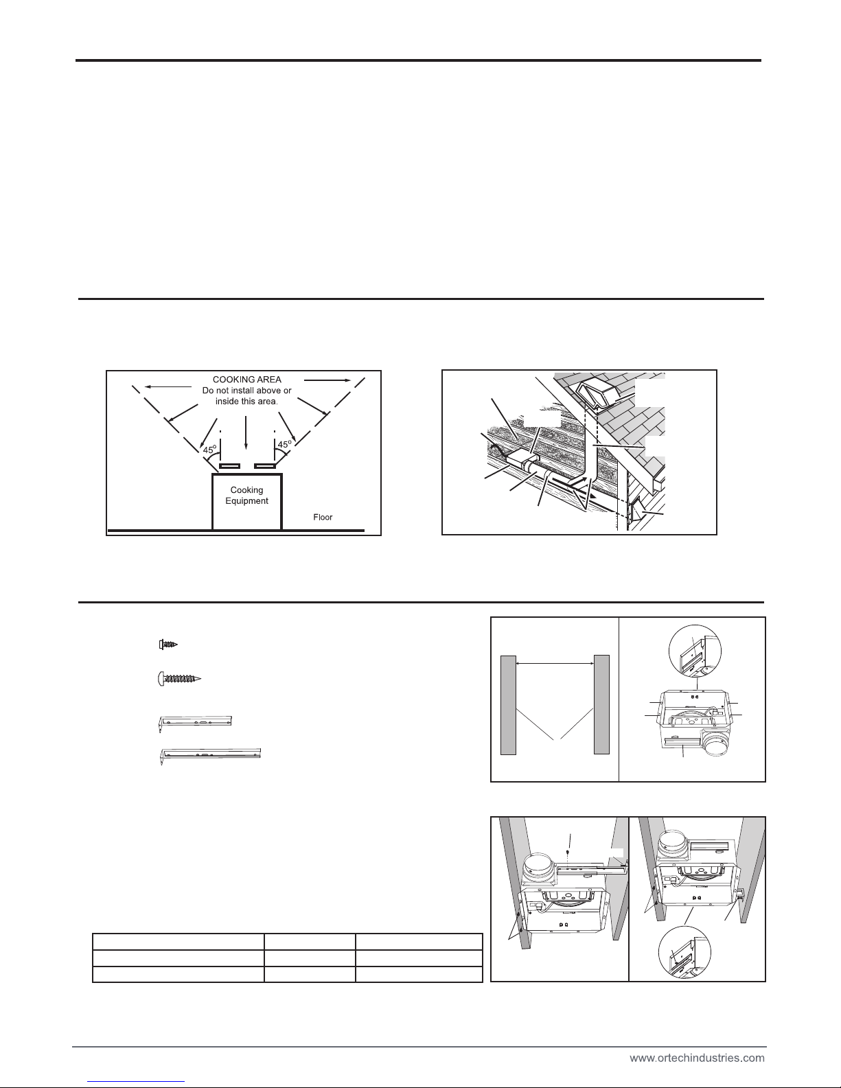
2. Mount with mountion holes and hanger bar
Slide one hanger bar into the channel on the housing and adjust as
needed to fit between framing. Hold housing in place so that the housing
contact the bottom of the joist, Screw housing to joist through the hole A
and hole B. Screw the hanger bar onto the other side of joist through the
hole (refer to the right diagram).
Screw hanger bar to housing with screw A.
OPERATION
PLAN THE INSTALLATION
1. Do not use in a cooking area.
2. Two ways to connect ductwork to a factory-shipped unit.
ASSEMBLY INSTRUCTIONS
2
4. Turn on power and check operation by turning on the shower or other humidity source until the fan turns on.
5. Repeat above steps if necessary.
When the temperature changes, humidity sensor values will have deviation.
TIMER ADJUSTMENT
The humidity sensing fan has a “T” (means timer) that can be adjusted from 5 to 60 minutes (factory-set at about 20 minutes). This “T” controls the length of time that the fan remains ON after the sensor has stopped sensing a rise in humidity
and the humidity level is below the user-adjustable set-point. To adjust the “T”:
1. Disconnect power at service entrance;
2. Through the grille, locate the slot marked “T”;
3. Carefully rotate the “T” adjustment to desired setting (from 5 to 60 minutes).
4. Check operation by turning on a humidity source until the fan turns on.
5. Turn humidity source off and time the unit.
6. Repeat above steps if necessary.
Distance A
JOIST
1. Before installation, you need to know:
Fig. 1 Fig. 2
Hole A
Hole B
Hole A
Hole B
Distance A
13 1/4 in to 15 1/2 in (336mm-394mm)
16 1/2 in to 18 7/8 in (419mm-480mm)
Hanger Bar
Channel
Channel A (Fig. 1)
Channel B (Fig. 2)
Hanger bar (short)
Hanger bar (long)
The choice of Hanger Bar
Channel A
Channel B
ST4.2*13mm
Screw A
Screw B
Hanger bar
(short)
Hanger bar
(long)
ST4.2*25mm
7 1/2 in (190mm)
13 3/8 in (340mm)
Screw A
Screw B
Note: Hanger bar (short) only can slide into channle A.
Screw A
Screw A
Screw A
Screw B
ROOF CAP*
(with built-in
damper)
ROUND
DUCT*
WALL CAP*
(with built-in
damper)
* Purchase
separately
POWER
CABLE*
INSULATION*
(Place around and
over Fan Housing.)
Seal gaps
around
Housing.
FAN
HOUSING
ROUND
ELBOW(S) *
Seal duct
joints with
tape.
Keep duct
runs short
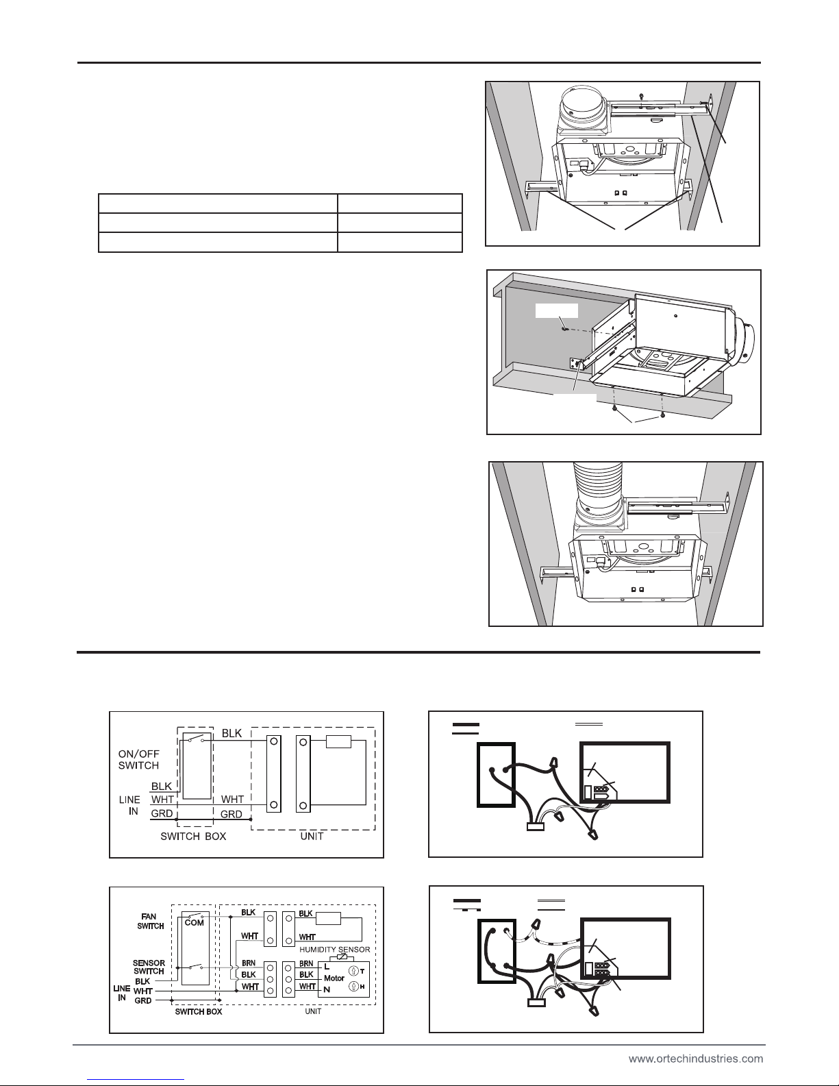
3. Mount with hanger bars only
Slide hanger bars onto housing and adjust as needed to fit between
framing. Extend the hanger bars to the width of the framing. Position the
ventilator with the hanger bar tabs wrapped around the bottom edge of
the framing, holding the ventilator in place.
Secure hanger bars to framing using one screw on each end of hanger
bar. (refer to the right diagram)
Screw hanger bar to housing with screw A.
4. Mount to I-joist
Slide one hanger bar (long) into channel B on the housing and adjust as
needed to fit between framing. Hold housing in place so that the housing
contacts the bottom of the joist. Screw housing to joist through the hole D
and hole C. Screw the hanger bar onto the other side of joist through the
hole (refer to the right diagram).
Screw hanger bar to housing with screw A.
5. INSTALL ROUND DUCTWORK
Connect the round ductwork (not included) to the damper/duct connector,
and run the ductwork to a roof or wall cap (not included). Using tape (not
included), secure all the ductwork connections so that they are air tight.
Run 120 V AC house wiring to the location of the fan. Use only UL-approved connectors (not included) to attach the house wiring to the
wiring plate. Refer to the wiring diagram, and connect the wires as shown.
ASSEMBLY INSTRUCTIONS
CONNECT ELECTRICAL WIRING
UNIT
BLACK (BLK)
SENSOR
SWITCH
SWITCH BOX
POWER SUPPLY
120V AC
GROUND (GRD)
BROWN (BRN)
WHITE (WHT)
WIRING
PLATE
FAN
RECEPTACLE
SENSOR
RECEPTACLE
UNIT
BLACK (BLK)
SWITCH BOX
FAN
SWITCH
FAN
SWITCH
POWER SUPPLY
120V AC
GROUND (GRD)
WHITE (WHT)
WIRING
PLATE
FAN
RECEPTACLE
3
FAN
FAN
For: ODS-8003-14 ODS-9003-14 ODS-1109 ODS-12012 ODS-15011
For: ODS-8003HS-14 ODS-9003HS-14 ODS-1109HS ODS-12012HS ODS-15011HS
Distance A
14 in to 23 1/2 in (356mm-597mm)
21 1/4 in to 23 1/2 in (540mm-597mm)
Hanger Bar A
Hanger bar (short)
Hanger bar (long)
The choice of Hanger Bar A
Hanger bar (long)
Hanger bar A
Screw A
Screw B
Screw A
Screw A
Screw B

Install ceiling material to complete the ceiling construction. Then, cut around
the fan housing.
To attach the grille assembly to the fan housing, pinch the grille springs on
the sides of the grille assembly, and position the grille into the housing with
the grille springs in the appropriate slots. Push the grille assembly towards
the ceiling to secure.
WARRANTY
INSTALL GRILLE
SERVICE PARTS
5
6
d
e
a
1
2
3
4
b
c
7
10
9
8
11
8
12
PART PART NAME Qty.
1
2
3
4
5
6
7
8
9
10
11
12
a
b
c
d
e
Housing
Damper / Duct Connector
Wiring plate
Screw
Blower Wheel
Wire Panel / Harness Assembly
Motor
1
2
1
1
1
1
1
1
1
1
3
1
4
4
1
4
1
Isolator
Motor Plate
Washer
Nut, Hex Lock
Grille Assembly (includes part 2)
Grille Spring
Hanger Bar Kit (short)
Hanger Bar Kit (long)
Screw
Humidity Sensor System (for sensor model)
* Blower Assembly includes part 6, 5, d, 4, c, b, a.
Replacement installation:
Remove the screw (part c), then take out the motor plate (part 4) from
the housing (part 10) by pushing down the rib in the plate while pulling
out on the side of the housing. Replace the broken parts.
4
WARNING: Before replacing, be sure to turn off power at power source.
ONE YEAR LIMITED WARRANTY from the original date of purchase against defects in material and workmanship.
This warranty is limited up to the amount of the original purchase price of the product, excluding any labor cost. For
inquiries please visit www.ortechindustries.com or call 1-888-543-6473.

Four Model ODS-8003HS-14 ODS-9003HS-14 ODS-1109HS ODS-12012HS ODS-15011HS
VENTILATEUR
AVERTISSEMENT
PRÉCAUTION
L ENTRETIEN
FONCTIONNEMENT
5
MODEL: ODS-8003-14 ODS-9003-14 ODS-1109 ODS-12012 ODS-15011
ODS-8003HS-14 ODS-9003HS-14 ODS-1109HS ODS-12012HS ODS-15011HS
fabricant.Pour toute question, veuillez contacter le fabricant
pas
qualifiée, qui doit suivre les
Veuillez suivre les les
tels
qu’expliqués par les fabricants d’équipement de chauffage, tels que publiés
Lorsque vous découpezv
électriques ou autres
générale seulement. N’utilisez pas cet
jusqu’à 12 ½ (45 degrés au maximum). Le raccordement pour le conduit d’aération
doit être dirigé vers
aux paliers du moteur ou augmenter le bruit ou déséquilibrer les roues à aubes,
d’huile. Si les paliers du moteur deviennent plus bruyants que d’habitude, remplacez le moteur
avec un moteur de rechange identique. La roue à aubes devra être remplacée aussi.
CONSERVER
Donnez ce manuel au propriétaire

FONCTIONNEMENT
PLANIFIE VOTRE INSTALLATION
6
INSTRUCTIONS POUR L’ASSEMBLAGE
2. Installation utilisant les trous de fixation et le support de montage.
Glissez un des supports de montage dans la rainure du boîtier et ajustez au
besoin afin de placer entre les solives. Tenez le boîtier en place afin de le
fixer vis-à-vis le bas de la solive. Vissez le boîtier à la solive en passant par
le trou A ainsi que le trou B. Vissez le support de montage de l’autre côté de
la solive à travers le trou (veuillez consulter l’illustration à droite). Vissez le
support de montage au boîtier en utilisant la vis A.
Distance A
Solive
1. Avant l’installation, veuillez prendre en note les détails suivants:
Fig. 1 Fig. 2
Trou A
Trou B
Trou A
Trou B
Distance A
13 1/4 po à 15 1/2 po (336mm-394mm)
16 1/2 po à 18 7/8 po (419mm-480mm)
Support de montage
Rainure
Rainure A (figure 1)
Rainure B (figure 2)
Support de montage (court)
Support de montage (long)
Le choix de support de montage
Rainure A
Rainure B
Filetage 4.2 * 13mm
Vis A
Vis B
Support de montage
(court)
Support de montage
(long)
Filetage 4.2 * 25mm
7 1/2 po (190mm)
13 3/8 po (340mm)
Vis A
Vis B
Nota: Seul le court support de montage peut glisser dans la rainure A.
Vis A
Vis A
Vis A
Vis B

POUR: ODS-8003-14 ODS-9003-14 ODS-1109 ODS-12012 ODS-15011
POUR: ODS-8003HS-14 ODS-9003HS-14 ODS-1109HS ODS-12012HS ODS-15011HS
BRUN
NOIR
TERRE
BLANC
NOIR
TERRE
BLANC
7
INSTRUCTIONS POUR L’ASSEMBLAGE
BRANCHEMENT DES FILS ÉLECTRIQUES
FAN
FAN
3. Installation utilisant seulement les supports de montage
Glissez les supports de montage dans la rainure du boîtier et ajustez au
besoin afin de le placer entre les solives. Ajustez les supports de montage
afin qu’ils touchent les solives. En tenant le ventilateur en place, arrangez-le
afin que les languettes situées sur les supports de montage enveloppent le
bord des solives. Fixez les supports de montage aux solives en utilisant une
vis à chacun des bouts de ceux-ci. (voir la figure à droite). Vissez le support
de montage au boîtier avec la vis A.
4. Installation aux solives en I
Glissez un des supports de montage (long) dans la rainure B du boîtier et
ajustez au besoin afin de le placer entre les solives. En tenant le boîtier en
place, assurez-vous que celui-ci touche le bas de la solive. Vissez le boîtier
à la solive en passant par les trous D et C. Vissez le support de montage
de l’autre côté de la solive en passant par le trou (veuillez voir la figure à
droite). Vissez le support de montage au boîtier avec la vis A.
5. L’installation du conduit rond
Raccordez le conduit rond (non compris) à l’amortisseur/le raccordement de
conduit, et joignez-le à un évent mural ou de toiture (non compris). En
utilisant du ruban adhésif pour conduit (non compris), assurez-vous qu’il n’y
ait aucune fuite d’air.
Distance A
14 po à 23 1/2 po (356mm-597mm)
21 1/4 po à 23 1/2 po (540mm-597mm)
Support de montage A
Support de montage (court)
Support de montage (long)
Support de montage (long)
Support de
montage A
Le choix de support de montage A .
Vis A
Vis B
Vis A
Vis A
Vis B
Relier le circuit électrique de votre maison de 120 V c.a. à l’emplacement du ventilateur. Utilisez seulement des raccords
homologués par UL pour relier le circuit électrique de votre maison à la plaque de câblage. Branchez les fils comme
illustré ci-dessous.

8
5
6
d
e
a
1
2
3
4
b
c
7
10
9
11
8
12
LIST DE PIECES DE RECHANGE
1
2
3
4
5
6
7
8
9
10
11
12
a
b
c
d
e
1
2
1
1
1
1
1
3
1
1
1
1
4
4
1
4
1
* 6, 5, d, 4, c, b, a.)
Remplacement de pièces: Enlevez la vis (piéce c), puis retirez la plaque du moteur (piéce 4)
du boîtier en poussant la nervure vers le bas, tout en tirant sur le côté du boîtier (piéce 10).
Remplacez les pièces défectueuses.
8
L’INSTALLATION DE LA GRILLE
Pincez ensemble les ressorts de la grille et insérez-les dans la plaque
du moteur dans le boîtier. Poussez la grille fermement vers le plafond.
Pour fixer la grille au boîtier du ventilateur, pincez les ressorts se
trouvant sur les côtés de la grille, puis installez la grille dans le boîtier
en insérant les ressorts dans leurs fentes respectives.
Poussez la grille vers le plafond pour la fixer fermement.
2
PIÈCE NOM DE LA PIÈCE Qté
GARANTIE LIMITÉE
(Pour capteur model)
AVERTISSEMENT: Avant de remplacer une pièce, assurez-vous de couper
l’alimentation électrique à la source.
(court)
(long)
grille
c
grille
d
d
d
b
b
f
f
GARANTIE limitée d'un an de la date d'achat contre tout vice de matériau et de fabrication. Cette garantie est limitée
à concurrence du montant du prix d'achat initial du produit, à l'exclusion de tout coût de main de œuvre. Si vous avez
des questions s'il vous plaît visitez notre site www.ortechindustries.com 1 888 543 6473 .
 Loading...