


VENTILATION FAN
WARNING
READ AND SAVE THESE INSTRUCTIONS
Installer: Leave this manual with the homeowner.
CAUTION
CLEANING & MAINTENANCE
OPERATION
TO REDUCE THE RISK OF FIRE, ELECTRIC SHOCK, OR INJURY TO PERSONS, OBSERVE THE FOLLOWING:
1. Use this unit only in the manner intended by the manufacturer. If you have questions, contact the manufacturer at the
address or telephone number listed in the warranty.
2. Before servicing or cleaning unit, switch power off at service panel and lock the service disconnecting means to prevent
power from being switching on accidentally. When the service disconnecting means cannot be locked, securely fasten
a prominent warning device, such as a tag, to the service panel.
3. Installation work and electrical wiring must be done by a qualified person(s) in accordance with all applicable codes and
standards, including fire-rated construction codes and standards.
4. Sufficient air is needed for proper combustion and exhausting of gases through the flue (chimney) of fuel burning equip ment to prevent backdrafting. Follow the heating equipment manufacturer’s guideline and safety standards such as those
published by the National Fire Protection Association (NFPA), and the American Society for Heating, Refrigeration and
Air Conditioning Engineers (ASHRAE), and the local code authorities.
5. When cutting or drilling into wall or ceiling, do not damage electrical wiring and other hidden utilities.
6. Ducted fans must always be vented to the outdoors.
7. Acceptable for use over a tub or shower when connected to a GFCI (Ground Fault Circuit Interrupter) - protected branch
circuit (ceiling installation only).
8. This unit must be grounded.
1. For general ventilating use only. Do not use to exhaust hazardous or explosive materials and vapors.
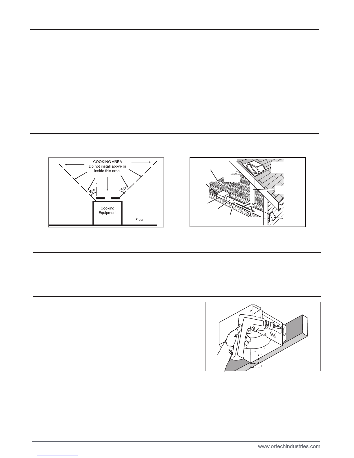
2. This product is designed for installation in ceilings up to a 12/12 pitch (45 degree angle). Duct connector must point up.
DO NOT MOUNT THIS PRODUCT IN A WALL.
3. To avoid motor bearing damage and noisy and/or unbalanced impellers, keep drywall spray, construction dust, etc. off
power unit.
4. Please read specification label on product for further information and requirements.
For quiet and efficient operation, long life, and attractive appearance - lower or remove grille and vacuum interior of unit
with the dusting brush attachment.
The motor is permanently lubricated and never needs oiling. If the motor bearings are making excessive or unusual noises, replace the motor with the exact service motor. The impeller should also be replaced.
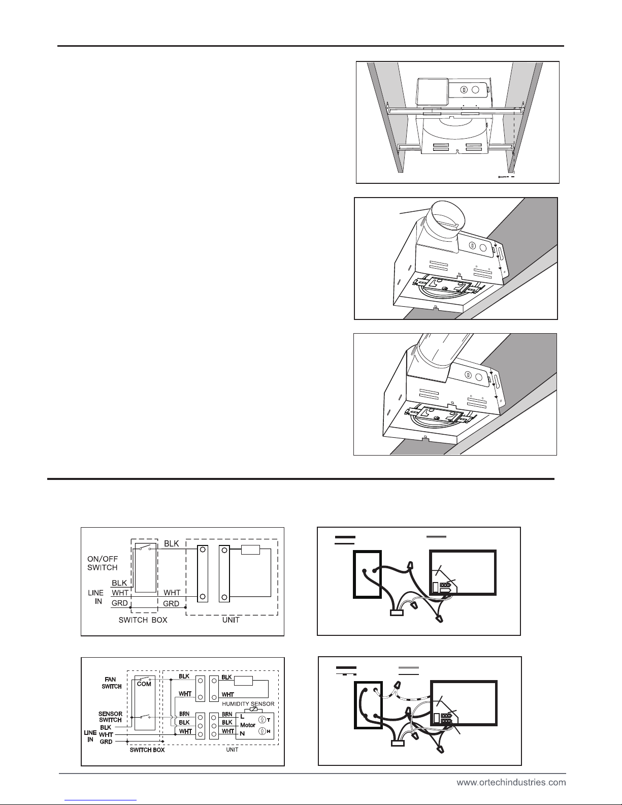
Use an on/off switch to operate this fan. See “Connect Wiring” for details.
For model OD-5006HS OD-8011HS
The humidity control and fan can be operated separately. Use a 1 or 2 function wall control. Do not use a dimmer switch
to operate the humidity control or light. See “Connect Wiring” for details.
SENSOR OPERATION
The humidity-sensing fan uses a sophisticated humidity sensor that responds to: (a) rapid to moderate (user-adjustable)
increases in humidity or (b) humidity above a user-adjustable set-point (50%-100% relative humidity). The humidity sensor may occasionally turn the fan ON when environmental conditions change. If the fan continuously responds to changing environmental conditions, “H” (means “humidity”) adjustment may be required. This figure is factory-set for about 75%
(Ambient temperature of 25℃).
SENSITIVITY ADJUSTMENT
The “H” has been factory set for most shower applications. However, if the fan is in a tub area or is being used for dampness control, the “H” may need to be increased toward maximum “+”. If the control is responding too often to changing
environmental conditions, movement toward less “-” “H” may be required.
To adjust the “H”:
1. Disconnect power at service entrance.
2. Through the grille, locate the slot marked “H”.
3. Carefully rotate the “H” adjustment toward “+” or “-”.
OD-5006
OD-5006HS
OD-8011
OD-8011HS
OPERATION
PLAN THE INSTALLATION
TYPES OF TYPICAL INSTALLATIONS
1. Do not use in a cooking area.
2. Two ways to connect ductwork to a factory-shipped unit.
ASSEMBLY INSTRUCTIONS
1. Housing mounted to I-joists (Start at “ASSEMBLY INSTRUCTIONS 1”)
2. Housing mounted to joists (Start at “ASSEMBLY INSTRUCTIONS 1” )
3. Housing mounted to truss (Start at step “ASSEMBLY INSTRUCTIONS 2”)
2
1.MOUNT HOUSING TO JOIST OR I-JOIST.
Hold the housing so that it is in contact with the bottom of the joist.
Place the fan housing next to the ceiling joist. Using wood screws
attach the housing loosely to the ceiling joist through the keyholes
in the mounting tabs. Adjust the housing to be flush with th
finished ceiling. For the grille to fit properly, the housing’s rim must
not extend beyond the finished ceiling surface. When the housing
is correctly adjusted, tighten the screws in the slots.
4. Turn on power and check operation by turning on the shower or other humidity source until the fan turns on.
5. Repeat above steps if necessary.
When the temperature changes, humidity sensor values will have deviation.
TIMER ADJUSTMENT
The humidity sensing fan has a “T” (means timer) that can be adjusted from 5 to 60 minutes (factory-set at about 20 minutes). This “T” controls the length of time that the fan remains ON after the sensor has stopped sensing a rise in humidity
and the humidity level is below the user-adjustable set-point. To adjust the “T”:
1. Disconnect power at service entrance;
2. Through the grille, locate the slot marked “T”;
3. Carefully rotate the “T” adjustment to desired setting (from 5 to 60 minutes).
4. Check operation by turning on a humidity source until the fan turns on.
5. Turn humidity source off and time the unit.
6. Repeat above steps if necessary.
ROOF CAP*
(with built-in
damper)
ROUND
DUCT*
WALL CAP*
(with built-in
damper)
* Purchase
separately
POWER
CABLE*
INSULATION*
(Place around and
over Fan Housing.)
Seal gaps
around
Housing.
FAN
HOUSING
ROUND
ELBOW(S) *
Seal duct
joints with
tape.
Keep duct
runs short
UNIT
BLACK (BLK)
SENSOR
SWITCH
SWITCH BOX
POWER SUPPLY
120V AC
GROUND (GRD)
BROWN (BRN)
WHITE (WHT)
FAN
RECEPTACLE
SENSOR
RECEPTACLE
FAN
SWITCH
FAN
Run 120 V AC house wiring to the location of the fan. Use only UL-approved connectors (not included) to attach the house wiring to the
wiring plate. Refer to the wiring diagram, and connect the wires as shown.
ASSEMBLY INSTRUCTIONS
CONNECT ELECTRICAL WIRING
3
2. MOUNT WITH HANGER BARS
Insret the hanger bars into the slots in the housing. Place the fan
housing between the joists, make sure the bottom of the housing
is even with the finished ceiling. Extend the hanger hars to the
joist. Use screws to secure the hanger bars to the
ceiling joists.
DUCT
3. ATTACH DAMPER/DUCT CONNECTOR
Snap the damper/duct connector onto the fan housing. The
connector must be flush with the top of the housing, and the
damper flap should fall closed.
4. INSTALL ROUND DUCTWOTK
Connect the round ductwork (not included) to the damper/duct connector,
and run the ductwork to a roof or wall cap (not included). Using tape (not
included), secure all the ductwork connections so that they are air tight.
D
For OD-5006HS OD-8011HS
For OD-5006 OD-8011
UNIT
BLACK (BLK)
SWITCH BOX
FAN
SWITCH
POWER SUPPLY
120V AC
GROUND (GRD)
WHITE (WHT)
WIRE
PANEL
WIRE
PANEL
FAN
RECEPTACLE
FAN

Install ceiling material to complete the ceiling construction. Then, cut around
the fan housing.
To attach the grille assembly to the fan housing, pinch the grille springs on
the sides of the grille assembly, and position the grille into the housing with
the grille springs in the appropriate slots. Push the grille assembly towards
the ceiling to secure.
WARRANTY
INSTALL GRILLE
SERVICE PARTS
PART PART NAME Qty.
1
2
3
4
5
6
7
8
9
10
Housing
Blower Wheel
Wire Panel / Harness Assembly
Motor
1
2
1
1
1
1
1
4
1
1
11aDamper / Duct Connector
1
1
Motor Plate
Grille Assembly
Grille Spring
* Blower Assembly includes part 3, 6, 7.
Replacement installation:
Remove the screw on motor plate (part 3), then take out the motor
plate (part 3) from the housing (part 9) by pushing down the rib in the
plate while pulling out on the side of the housing. Replace the broken
parts.
4
WARNING: Before replacing, be sure to turn off power at power source.
A
1
2
3
4
6
5
7
8
8
9
10
a
11
Hanger Bars
Humidity Sensor system (for sensor model)
Wiring plate
Screw
ONE YEAR LIMITED WARRANTY from the original date of purchase against defects in material and workmanship.
This warranty is limited up to the amount of the original purchase price of the product, excluding any labor cost. For
inquiries please visit www.ortechindustries.com or call 1-888-543-6473.

OD-5006
OD-5006HS
OD-8011
OD-8011HS
Four Model OD-5006HS OD-8011HS
VENTILATEUR
AVERTISSEMENT
PRECAUTION
L ENTRETIEN ET LE NETTOYAGE
FONCTIONNEMENT
5

6
FONCTIONNEMENT
PLANIFIE VOTRE INSTALLATION
INSTALLATIONS TYPIQUES
1. Boîtier monté sur solive en « I » (instructions pour l’assemblage 1)
2. Boîtier monté sur solive (instructions pour l’assemblage 1)
3. Boîtier monté sur poutre triangulée (instructions pour l’assemblage 2)
INSTRUCTIONS POUR L’ASSEMBLAGE
Placez le boîtier du ventilateur près de la solive
du plafond.
Fixez lâchement le boîtier à la solive en
insérant des vis à bois
dans les encoches en trou de serrure des languettes de
montage.
Réglez la position du boîtier
de façon
à ce qu’il soit
au même
niveau que le plafond fini. Pour que la grille
puisse être
installée
correctement, le bord du boîtier ne doit pas dépasser la
surface
du plafond fini. Une fois que le boîtier
e
st bien placé,
serrez les
vis dans les encoches.
1. INSTALLATION DIRECTE SUR UNE SOLIVE
OU UNE SOLIVE EN I
Tenez le boîtier en place de façon à ce qu’il soit en contact avec
la partie inférieure de la solive.

7
3. FIXATION DU RACCORD POUR CONDUITAVEC REGISTRE
Enclenchez le raccord pour conduit avec registre sur le boîtier du
ventilateur. Assurez-vous que le raccord est au même niveau que
le bord supérieur du boîtier et que l’obturateur à registre se ferme.
4.
INSTALLATION DU CONDUIT ROND
Reliez le conduit rond (non inclus) au raccord pour conduit avec
registre, puis reliez ce conduit à un évent de toit ou de mur (non
inclus). Scellez tous les raccords avec du ruban adhésif (non
inclus) pour vous assurer qu’ils sont solides et étanches à l’air.
D
INSTRUCTIONS POUR L’ASSEMBLAGE
2. INSTALLATION AVEC BARRES DE SUSPENSION
Insérez les barres de suspension dans les fentes du boîtier. Placez
le boîtier du ventilateur entre les solives de façon à ce que le bord
inférieur du boîtier soit au même niveau que le plafond fini.
Allongez les barres
de suspension jusqu’aux solives.
Utilisez
des vis pour fixer les barres de suspension aux solives.
POUR: OD-5006 OD-8011
POUR: OD-5006HS OD-8011HS
Amenez l’installation domestique de 120 V c.a. à l’emplacement du ventilateur. Utilisez seulement des connecteurs
homologués par UL pour relier l’installation domestique à la plaque de connexion. Branchez les fils comme l’illustre le
diagramme ci-contre.
BRANCHEMENT DES FILS ÉLECTRIQUES
BRUN
NOIR
TERRE
BLANC
NOIR
TERRE
BLANC
FAN
FAN

a
A
INSTALLATION DE LA GRILLE
Terminez la préparation du plafond en y installant le matériau. Puis,
découpez ce matériau autour du boîtier du ventilateur.
Pour fixer la grille au boîtier du ventilateur, pincez les ressorts se
trouvant sur les côtés de la grille, puis installez la grille dans le boîtier
en insérant les ressorts dans leurs fentes respectives.
Poussez la grille vers le plafond pour la fixer fermement.
LIST DE PIECES DE RECHANGE
1
2
3
4
5
6
7
8
9
10
11
1
2
1
1
1
1
1
4
1
1
1
1
* 3, 6, 7)
Remplacement de pièces:
Enlevez la vis, puis retirez la plaque du moteur (piéce 3) du boîtier en
poussant la nervure vers le bas, tout en tirant sur le côté du boîtier (piéce 9).
Remplacez les pièces défectueuses.
PIÈCE NOM DE LA PIÈCE Qté
(Pour capteur model)
AVERTISSEMENT: Avant de remplacer une pièce, assurez-vous de couper
l’alimentation électrique à la source.
8
GARANTIE LIMITÉE
1
2
3
4
6
5
7
8
8
9
10
a
11
GARANTIE limitée d'un an de la date d'achat contre tout vice de matériau et de fabrication. Cette garantie est limitée
à concurrence du montant du prix d'achat initial du produit, à l'exclusion de tout coût de main de œuvre. Si vous avez
des questions s'il vous plaît visitez notre site www.ortechindustries.com 1 888 543 6473 .
 Loading...