

Page 1

ORTEC
®
®
DSPEC Pro
Digital Gamma-Ray Spectrometer
Hardware User’s Manual
Printed in U.S.A. ORTEC Part No. 794380 0914
Manual Revision D
Page 2

Advanced Measurement Technology, Inc.
(“AMT”)
WARRANTY
AMT warrants that the items will be deliv ered free from defects in material or workmanship. AMT m akes no other warranties,
express or implied, and sp ecifically NO WARRANT Y OF MERCHANTABILITY OR FITNESS FOR A PARTICULAR
PURPOSE.
AMT’s exclusive liability is limited to repairing or replacing at AMT’s option, items found by AMT to be defective in
workmanship or materials within one year from the date of delivery. AMT’s liability on any claim of any kind, including
negligence, loss, or damages arising out of, connected with, or from the performance or breach thereof, or from the
manufacture, sale, delivery, resale, repair, or use of any item or services covered by this ag reement or purchase order, shall in
no case exceed the price allocable to the item or service furnished or any part thereof that gives rise to the claim . I n the ev ent
AMT fails to manufacture or deliver item s called for in this agreement or purchase order, AMT’s exclusive liability and buyer’s
exclusive remedy shall be release of the buyer from the obliga tion to pay the purchase price. I n no ev ent shall AMT be liable
for special or consequential damages.
Quality Control
Before being approved for shipment, each AMT instrum ent must pass a stringent set of quality control tests designed to expose
any flaws in materials or workmanship. Permanent records of these tests are maintained for use in warranty repair and as a
source of statistical information for design improvements.
Repair Service
If it becomes necessary to return this instrument for repair, it is essential that Customer Services be contacted in advance of
its return so that a Return Authorization Number can be assig ned to the unit. Also, A MT m ust be informed, either in writing ,
by telephone [(865) 482-4411] or by facsimile transmission [(865) 483-2133], of the nature of the fault of the instrum ent being
returned and of the model, serial, and revision (“Rev” on rear panel) numbers. Failure to do so may cause unnecessary delays
in getting the unit repaired. The AMT standard procedure requires that instruments returned for repair pass the same quality
control tests that are used for new-production instruments. Instruments that are returned should be packed so that they will
withstand normal transit handling and must be shipped PREPAID via Air Parcel Post or United Pa rcel Service to the designated
AMT repair center. The address label and the package should include the Return Authorization Number assigned. Instrum ents
being returned that are damaged in transit due to inadequate packing will be repaired at the sender’s expense, and it will be the
sender’s responsibility to mak e claim with the shipper. Instruments not in warranty should follow the same procedure and AMT
will provide a quotation.
Damage in Transit
Shipments should be examined immediately upon receipt for evidence of external or concealed damage. The carrier making
delivery should be notified immediately of any such damage, since the carrier is normally liable for damage in shipment.
Packing materials, waybills, and other such documentation should be preserved in order to establish claims. After such
notification to the carrier, please notify AMT of the circumstances so that assistance can be provided in making dam age claims
and in providing replacement equipment, if necessary.
Copyright © 2014, Advanced Measurement Technology, Inc. All rights reserved.
ORTEC
respective owners.
NOTICE OF PROPRIETARY PROPERTY — This document and the information conta ined in it are the proprietary property of
AMETEK Inc. It may not be copied or us ed in any m anne r nor ma y any of the i nform ation in or u pon it be us ed for any purpose w ithout the
express written consent of an authorized agent of AMETEK Inc.
®
is a registered trademark of Advanced Measurement Technology, Inc. All other trademark s u s ed h erein are th e property of their
Page 3

ADDITIONAL WARRANTY STATEMENT
Please note that the DSPEC Pro contains no user-serviceable parts.
Breaking the seal on the case voids your warranty. The DSPEC Pro
should be opened only by ORTEC-authorized service personnel.
iii
Page 4

[Intentionally blank]
iv
Page 5

TABLE OF CONTENTS
Installation — page 19
WARRANTY ................................................................ ii
ADDITIONAL WARRANTY STATEMENT ...................................... iii
Safety Instructions and Symbols................................................ viii
Cleaning Instructions......................................................... viii
1. INTRODUCTION .......................................................... 1
1.1. Why the DSPEC Pro? ................................................... 1
1.1.1. DSPEC Pro Technologies .......................................... 1
1.1.2. Proven Technologies of the DSPEC Family ............................ 2
1.2. Enhanced Throughput Mode .............................................. 3
1.3. Resolution Enhancement Mode Corrects for Charge Trapping ................... 4
1.4. The Low Frequency Rejector (LFR) Filter ................................... 5
1.5. Ballistic Deficit and Adjusting the Flattop Duration ........................... 8
1.6. Zero Dead-Time (ZDT) Mode............................................. 9
1.6.1. Off — Uncorrected Spectrum Only .................................. 10
1.6.2. NORM_CORR — ZDT and Uncorrected Spectra Stored................. 11
1.6.3. CORR_ERR — ZDT and Error Spectra Stored......................... 11
1.6.4. Choosing a ZDT Mode ............................................ 12
1.6.4.1. The NORM_CO RR Diagnostic Mode ........................ 13
1.6.4.2. To Summarize ........................................... 13
1.6.4.3. More Information......................................... 14
1.7. DSPEC Pro SMART-1 HPGe Detector Support .............................. 14
1.7.1. SMART-1 HPGe Detector Construction .............................. 15
1.7.2. Using Older Detectors ............................................ 15
1.7.3. How State of Health (SOH) is Monitored ............................. 15
1.8. Host Computer and Software Requirements ................................. 16
1.9. About this Manual ..................................................... 16
2. GETTING STARTED ...................................................... 17
2.1. The DSPEC Pro ....................................................... 17
2.1.1. Front Panel ..................................................... 17
2.1.1.1. The Display ............................................. 17
2.1.1.2. Controls ................................................ 18
2.1.2. Rear Panel...................................................... 18
2.2. Software and Hardware Installation ....................................... 19
v
Page 6

DSPEC Pro® Digital Gamma-Ray Spectrometer User’s Manual 794380D / 0914
2.2.1. Step 1: Install the CONNECTIONS Driver Update ....................... 20
2.2.2. Step 2: Install MAESTRO......................................... 20
2.2.3. Step 3: Connect the DSPEC Pro to the Computer ...................... 21
2.2.4. Step 4: Run MCB Configuration to Communicate With Your MCBs....... 21
2.2.4.1. Configuring a New Instrument .............................. 22
2.2.4.2. Customizing ID Numbers and Descriptions .................... 22
2.2.5. Attaching More Than One DSPEC Pro to the Computer ................. 23
2.2.6. Connecting to and Disconnecting from the Computer ................... 24
2.3. DSPEC Pro MCB Properties in MAESTRO................................. 24
2.3.1. Amplifier....................................................... 24
2.3.2. Amplifier 2 ..................................................... 26
2.3.2.1. InSight Mode ............................................ 27
Mark Types ......................................... 29
2.3.3. Amplifier PRO .................................................. 30
2.3.3.1. “Training” the Resolution Enhancer .......................... 32
To Enable and Train the Enhancer ....................... 32
To Turn the Enhancer Off.............................. 33
2.3.4. ADC .......................................................... 33
2.3.5. Stabilizer....................................................... 34
2.3.6. High Voltage ................................................... 35
2.3.7. About ......................................................... 36
2.3.8. Status ......................................................... 36
2.3.9. Presets......................................................... 39
2.3.10. MDA Preset ................................................... 40
2.4. Setting the Rise Time in Digital MCBs..................................... 42
2.5. Troubleshooting ....................................................... 43
2.5.1. MAESTRO Does Not Connect with the DSPEC Pro .................... 43
3. SPECIFICATIONS......................................................... 45
3.1. DSPEC Pro........................................................... 45
3.1.1. Electrical and Mechanical ......................................... 47
3.1.2. Connectors ..................................................... 48
3.2. HPGe High-Voltage Detector Interface Modules ............................. 48
3.3. Feature Mask Bits ..................................................... 49
4. FIRMWARE COMMANDS AND RESPONSES ................................. 53
4.1. Command Format...................................................... 53
4.2. Error Codes .......................................................... 53
4.2.1. Dollar Response Records .......................................... 54
4.2.2. MCB Commands ................................................ 55
vi
Page 7

794380D / 0914 TABLE OF CONTENTS
APPENDIX A. STATE-OF-HEALTH BIT DEFINITIONS........................... 91
APPENDIX B. LIST MODE IN THE DSPEC PRO ................................. 93
B.1. List Mode Data ....................................................... 93
B.1.1. Spectrometer Data Format......................................... 93
INDEX..................................................................... 97
vii
Page 8

Safety Instructions and Sy mbols
This manual contains up to three levels of safety instructions that must be observed in order to avoid
personal injury and/or damage to equipment or other property. These are:
DANGERIndicates a hazard that could result in death or serious bodily harm if the safety instruction is
not observed.
WARNING Indicates a hazard that could result in bodily harm if the safety instruction is not observed.
CAUTION Indicates a hazard that could result in property damage if the safety instruction is not
observed.
In addition, the following symbols may appear on the product:
DANGER – Hazardous voltage
ATTENTION – Consult the manual in all cases where this symbol is
marked in order to determine the nature of the potential hazards and any
actions that must be taken to avoid them
Protective earth (ground) terminal
Please read all safety instructions carefully and make sure you understand them fully before attempting to
use this product.
Cleaning Instructions
To clean the instrument exterior:
! Disconnect the instrument from the power source.
! Remove loose dust on the outside of the instrument with a lint-free cloth.
! Remove remaining dirt with a lint-free cloth dampened in a general-purpose detergent and water
solution. Do not use abrasive cleaners.
CAUTION To prevent moisture inside of the instrument during external cleaning, use only
enough liquid to dampen the cloth or applicator.
! Allow the instrument to dry completely before reconnecting it to the power source.
viii
Page 9

[Intentionally blank]
ix
Page 10
x
Page 11

1. INTRODUCTION
The DSPEC Pro® is the next generation in digital signal processing-based gamma-ray spectrometers from O RTEC. Perhaps the most versatile digital spectrometer on the market today, the
DSPEC Pro features all of the spectral acquisition, MCA emulation, and computer control you
expect from our DSPEC family of instruments, plus specialized features for more challenging
gamma-ray spectroscopy applications. The DSPEC Pro offers superior performance for more
applications than any other gamma-ray spectrometer, delivered across a high-speed USB connection. Whether your application is in nuclear pow er, non-destructive analysis, research
physics, homeland security, real-time monitoring, or nuclear safeguards, the DSPEC Pro gives
you exceptional ease of use, flexibility, rock-solid count-rate and peak-position stability, and
impressive overall performance.
1.1. Why the DSPEC Pro?
ORTEC digital signal processing (DSP) offers more options in optimizing the output signal of
high-purity germanium (HPGe) detectors. The DSPEC Pro builds on our DSP techniques and
combines them with the proven technologies of the DSPEC family in one compact, economical
package with high-speed USB connectivity — no other instrument com e s close for HPGe
applications.
1.1.1. DSPEC Pro Technologies
Resolution Enhancer In ORTEC DSPEC products, the flattop width parameter of the trapezoidal filter automatically corrects for ballistic deficit. Unfortunately, this doesn’t compensate
for resolution loss due to charge trapping, which results in variations in charge collection efficiency over the crystal volume. The DSPEC Pro introduces our new Resolution Enhancer, which
enables you to correct for charge trapping by “training” the spectrometer to accomm odate the
particular performance of your detector.
Enhanced Throughput Mode This signal processing method allows the spectrom eter to begin
sampling the next pulse before the preceding one has returned to baseline. The effect is optimum
throughput while maintaining resolution and peak shape.
List Mode In List Mode, the DSPEC Pro records and stores the pulse value with a time-stamp
for every pulse generated by the detector. With List Mode, you can write your own programs
that can reconstruct histograms for any time segment without dead time between histograms, or
make histograms for overlapping time slices. Data can be stored easily for reconstruction of any
time frame needed. If your application requires real real-time monitoring, no other instrument
comes close for HPGe applications.
1
Page 12

DSPEC Pro® Digital Gamma-Ray Spectrometer User’s Manual 794380D / 0914
1.1.2. Proven Technologies of the DSPEC Family
High-Speed USB Interface Connect the DSPEC Pro via high-speed USB to any computer
®
running under Microsoft
Windows® 8, 7, or XP® SP3. A nearly unlimited number of DSPEC
Pros (as well as any combination of other ORTEC USB instruments) can be connected to your
computer via USB hubs (and across the network). A s an ORTEC C
ONNECTIONS multichannel
buffer (MCB), DSPEC Pro works in both standalone and networked configurations.
Low-Frequency Rejector (LFR) Filter Uniquely designed for mechanically cooled HPGe
1
detectors, our Low-Frequency Rejector
digital filter surpasses all signal processing methods for
reducing the effects of microphonics, ground loops, and virtually all other sources of periodic
noise for HPGe and NaI(Tl) spectrometry.
Zero Dead-Time Correction The DSPEC Pro features our innovative ZDT™ mode of operation, an alternative to the classical “extended-live-time clock.” The ZDT method produces accurate results in all situations and completely overcomes some of the shortcomings of extended
live-time methods. Moreover, the new ZDT method overcomes some limitations in previous
“loss-free” dead-time correction methods. Most notably, the ZDT mode does not require any
manual adjustments and is capable of computing the statistical uncertainty of the corrected
2
spectrum.
Single-Cable Connection to Detectors DSPEC Pro uses the unique ORTEC Detector Interface
Module (DIM) for single-cable connection between the DSPEC Pro and the detector. The DIM
is designed to supply bias close to the detector so the cable carries only signal and low-voltage
power — no longer is high-voltage bias, and its associated dangers, carried over long distances.
SMART-1™ Support Detectors equipped with the SMART-1 technology have their recommended bias values preset at the factory. N o more shuffling through paperwork or looking for
tags on the detector to find the right bias setting. Simply turn on the electronics and the
SMART-1 detector senses the detector temperature and applies the right high-voltage bias.
®
Our SMART-1 detectors also allow our more recent MCBs, such as the DSPEC
-50 and digiDART, to m onitor and display detector state of health (SOH) during acquisition, including
detector temperature, preamplifier power, bias overrange, and bias on/off state. This continuous
SOH monitoring ensures the integrity of the acquired data. A quick check of the SOH flag in the
SMART-1 detectors shows if any parameter deviated from specification during the measurement. This is vitally important for environmenta l samples that must be counted for long periods
of time and regulatory-driven samples where chain-of-custody integrity means everything.
1
Patent pending.
2
Patent number 6,327,549.
2
Page 13

794380D / 0914 1. INTRODUCTION
Sample Changer Connections and Controls The DSPEC Pro connects easily to many types
of automatic sample changer.
Compact, Convenient Connectivity A small footprint means that the DSPEC Pro can sit right
on the desktop. Lightweight but rugged, multiple units can be stacked on top of one another via
their interlocking cases without fear of sliding or tipping. The easy-to-read, backlit LC D screen
displays the instrument ID, name, preset count conditions, current live and real time, dead-time
percentage (if active), input count rate, HV status and value, and, the serial number of SMART-1
detectors.
Use a USB hub to quickly connect multiple instruments to your computer. ORTEC C
TIONS software supports any combination of USB devices (to a total of 127) connected to a
ONNEC-
particular computer. In addition, any number of other ORTEC multichannel buffers (USB and
other interfaces) can be connected to the same system.
Standard DSPEC-Family Features The DSPEC Pro also offers the InSight™ Virtual Oscilloscope, which allows you to optimize detector performance for a given application from the com-
3
puter; our easy automatic pole-zero adjustment
accurate Gedcke-Hale extended live-time correction method.
and automatic baseline restorer4; and the highly
5
1.2. Enhanced Throughput Mode
To optimally process an input pulse stream, and thereby obtain the best spectral resolution, the
signal processing device should allow the input signal to return to baseline before beginning to
process the subsequent pulse. However, in cases where some loss of resolution is acceptable, it
is possible for a DSP to begin processing a subsequent pulse before the first pulse has returned
to the baseline, provided the first pulse has returned to baseline when the peak-detect of the
second pulse occurs.
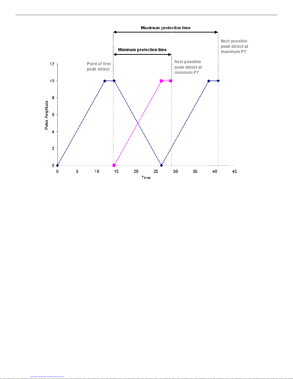
The ORTEC Enhanced Throughput Mode takes advantage of this feature of digital signal processing by allowing you to adjust the delay between the peak-detect and the start of processing
of the next pulse. The dead time for a conventionally processed pulse is the sum of the pulse’s
rise time, flattop, and fall time. By contrast, the dead time in ORTEC’s Enhanced T hroughput
Mode can be as little as the rise time plus the flattop. These two scenarios are illustrated in
Fig. 1. The DSPEC Pro lets you set a protection time (PT), following a peak-detect, that blocks
3
Patent number 5,872,363.
4
Patent number 5,912,825.
5
Ron Jenkins, R. W. Gould, and Dale Gedcke, Quantitative X-Ray Spectrometry (New York: Marcel Dekker,
Inc.), 1981, pp. 266–267.
3
Page 14

DSPEC Pro® Digital Gamma-Ray Spectrometer User’s Manual 794380D / 0914
subsequent peak-detects until the protection time has elapsed. Note that the conventional dead
time illustrated in Fig. 1 is the same as the maximum protection time in Enhanced
Throughput Mode.
The protection-time settings with the low-frequency rej ector (LFR) filter off range between:
! Minimum PT (highest throughput) = (1 × rise time) + (1 × flattop)
! Maximum PT = (2 × rise time) + (1 × flattop)
With LFR on, the protection-time settings range between:
! Minimum PT = (3 × rise time) + (2 × flattop)
! Maximum PT = (6 × rise time) + (3 × flattop)
1.3. Resolution Enhancement Mode Corrects for
Charge Trapping
When a gamm a ray interacts with a germanium detector, mobile electrons and holes are generated. The electrons and holes are swept to the detector electrodes by the electric field inside
the detector. If all the electrons and holes travel the complete path to the detector electrodes, a
signal is produced proportional to the energy deposited in the detector by the gamma ray. If
some of the electrons or holes do not reach the electrodes, the signal produced will be smaller
than expected. The process of interrupting the movement of an electron or hole is referred to as
“charge trapping.”
If charge trapping did not occur, the resolution of a reasonably low-noise germ anium detector
60
for the 1.33-MeV gamma ray from
cally have a resolution of 1.8 to 2.2 keV FWHM. ORTEC’s Charge T r apping Corrector (CTC)
helps reduce this energy resolution loss caused by charge trapping, yielding the DSPEC Pro’s
Resolution Enhancer Mode. The controls are accessed via the Acquire/MCB Properties...
command in the accompanying MAESTRO
BW) and other ORTEC C
ONNECTIONS applications.
Co would be about 1.5 keV FWHM. Real detectors typi-
®
Multichannel Analyzer Emulation Software (A65-
Charge trapping is caused by various defects and impurities in the germanium crystal, and thus
varies from detector to detector. The am ount of charge lost due to trapping also depends on the
distance the charge carrier (electron or hole) has to move to reach the collecting electrode. If the
carrier must travel a long distance, it is more likely to be trapped. If some of the charge is
trapped, it does not contribute to the signal. The reduced signals have a different rise time than
the full signals. The relationship between rise time of the signal and charge trapping is the basis
of the Charge Trapping Corrector.
4
Page 15
794380D / 0914 1. INTRODUCTION
Figure 1. Demonstration of the DSPEC Pro’s Minimum and Maximum Protection
Times in Enhanced Throughput Mode. At the maximum protection-time setting, the
DSPEC Pro processes pulses in the conventional way.
The digital filter in the DSPEC Pro measures the amount of charge collected for each event and
uses the result to increment the spectrum memory location associated with that charge measurement. The Charge Trapping Corrector also measures the pulse rise time for the event. The pulse
rise time is used to adjust the very fine gain. For each pulse, the measured charge is increased by
the appropriate fine gain factor to correct for the signal lost due to carrier trapping.
1.4. The Low Frequency Rejector (LFR) Filter
In designing a multichannel buffer (MCB) that can be used in conjunction with m echanical
coolers, ORTEC has developed a new digital filter, the Low Frequency Rejector (LFR) filter,
capable of correcting the pulse output signal for changes in the baseline caused by coolerinduced microphonics. In ma ny ways digital filters are easier to understand than their analog
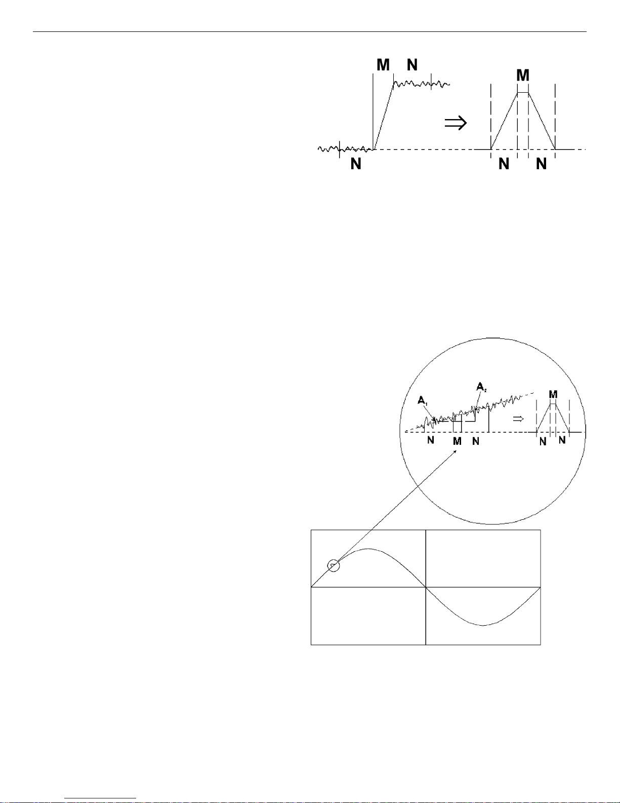
counterparts. Figure 2 shows the voltage step output produced at the preamplifier by the collection of charge produced by absorption of a gamma-ray and the resulting trapezoidal weighting
function in a digital spectrometer. The difficulty in the measurement is to precisely determine
the height of the step pulse because the baseline contains noise. A fairly obvious estimate of the
5
Page 16
DSPEC Pro® Digital Gamma-Ray Spectrometer User’s Manual 794380D / 0914
step signal is obtained by averaging the
digitized samples of the signal before and
after the step. M samples immediately after
the event are first ignored, to allow for a
maximum rise time of M times the sample
interval. N samples of the baseline prior to
the step pulse are averaged and then subtracted from the average of N samples
taken after the step pulse. This simple
procedure produces a trapezoidal weight-
Figure 2. Typical Trapezoidal Weighting Function
(right) Arising from Detector Preamplifier Output
Signal (left).
ing function with a rise time of N sample
intervals and a flattop of M sample intervals. The maximum value of the trapezoid output, occurring at the end of the flattop, is the best estimate of the step height and therefore the gamma-ray
energy. With a proper selection of M and N, this filter is very nearly the optimum filter for a
system with noise arising only from the detector leakage (parallel noise) and the FET current
(series noise).
The trapezoidal filter is essentially independent of dc offsets, since the averaging
and subtracting removes the dc component
of the signal. Unfortunately, it is just as sensitive as analog filters to slowly varying
signals such as those produced in microphonic noise. Figure 2 shows the output of
the trapezoidal filter is equal to the slope
of the baseline signal multiplied by the
full width at half maxim um (FWHM) of
the trapezoid. If a step pulse were to be
measured on such a base-line, the filter
output value would be too great by an
error equal to the difference between the
average values A1 and A2. Since the
microphonic noise component in a signal
is approximately a sine wa ve, as illustrated in Fig. 3, the error induced can be
positive, negative, or zero. This error
signal adds to the width of the spectral
lines, appearing as degraded resolution
performance from the detector, and can
in many cases be a dominant noise
source, especially at lower energies.
Figure 3. Example of Weighting Function Output
Resulting from the Positive Slope Due to LowFrequency Noise (shown as a sine wave).
6
Page 17
794380D / 0914 1. INTRODUCTION
The ORTEC LFR filter removes most of the microphonic noise by estimating the microphonicinduced error signal on a pulse-by-pulse basis and subtracting the estimated error signal from the
trapezoid output. As noted above, the error signal is proportional to the slope of the baseline
during the energy measurement. If the slope is known, then so is the error introduced by the
microphonics. An excellent estim ate of the slope can be obtained by using the trapezoidal filter
itself to measure the slope both before and after the energy measurement. Since the digital filter
is always sampling the input signal, it is only necessary to store (1) the values measured before
the event is detected, (2) the gamma-ray energy measurem ent, and (3) the values measured after
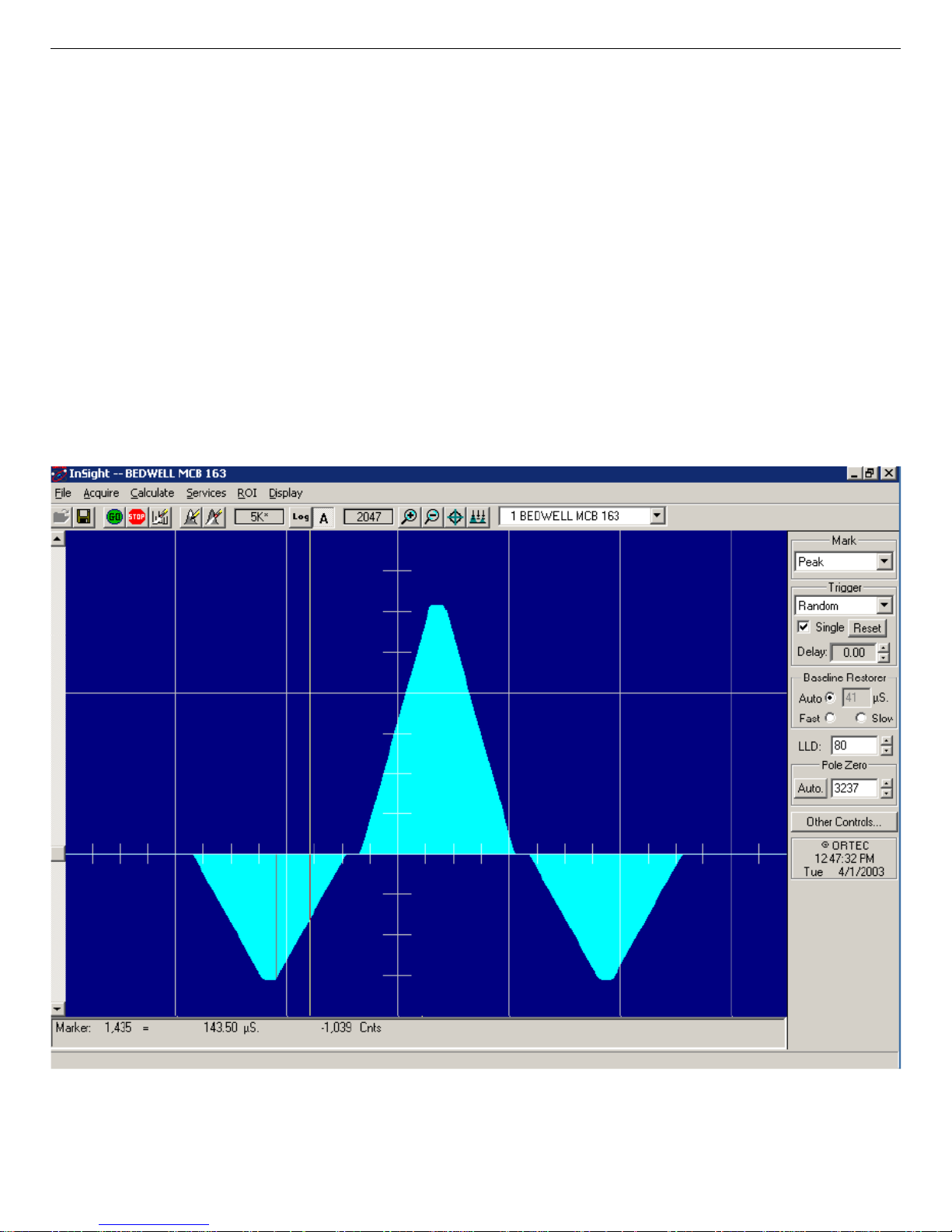
the event is detected. The modified trapezoidal digital filter for LFR from an InSight Virtual
Oscilloscope trace is shown in Fig. 4. A suitably weighted and averaged value of the before and
after slope measurement is then subtracted from the energy measurement producing a measurement essentially free of microphonic noise. Although the inherent increase in the pulse processing time increases the dead time of the system, the resolution can be greatly enhanced when
periodic noise is present.
Figure 4. LFR-Enabled Digital Filter.
7
Page 18

DSPEC Pro® Digital Gamma-Ray Spectrometer User’s Manual 794380D / 0914
To switch to LFR mode, click the Amplifier PRO tab under Acquire/MCB Properties..., and
mark the Low Frequency Rejector checkbox (see Section 2.3.3). Note that you cannot optimize
or pole-zero the DSPEC Pro while in LFR m ode. The Optimize feature should be used with the
LFR filter off (checkbox unmarked). Subsequent measurements can then be taken with the LFR
filter on.
1.5. Ballistic Deficit and Adjusting the Flattop Duration
In germanium detectors it takes a variable amount of time to collect all of the charge released in
the detector diode when a gamma ray deposits energy in the detector. The duration of this charge
collection time depends on the dimensions of the detector, the geometry of the electrodes, and
the points at which energy is deposited in the detector. A small, planar detector has charge collection times that vary from 50 ns to 100 ns, whereas a large coaxial detector is characterized by
charge collection times that vary from 100 ns to 700 ns. The variability of the charge collection
time within a specific detector is the source of the resolution degradation described by the
ballistic deficit effect.
The ballistic deficit becomes a significant source of resolution degradation when very short
shaping times are selected in order to reduce dead time and improve the high counting-rate limit.
For a digital filter having the shape of a symmetrical triangle in the time domain, the output
pulse begins to rise as soon as the gamma ray is detected. It continues to rise until it reaches a
peak amplitude at a time specified by the currently selected rise/fall time (this is the Rise Time
parameter entered on the Am plifier 2 tab under Acquire/MCB Properties...; see Section 2. 3.2).
Beyond this peak-amplitude time, the pulse falls back to the baseline to allow a subsequent
gamma ray to be processed. If all the charge has not been collected by the detector by the designated time for peak amplitude, there will be a deficit in the measured peak amplitude and a
broadening of the pulse width. The deficit in amplitude is called the ballistic deficit. Obviously,
events that result in a faster charge collection time will suffer less deficit and less increase in
pulse width than those yielding a slower charge collection tim e, even though the deposited
energy was identical. Thus, the ballistic deficit resulting from variable charge collection times
broadens the energy resolution for that gamma ray.
If the longest charge collection time is negligible compared to the rise time of the filter pulse, the
ballistic deficit will be imperceptible, and the energy resolution will not be degraded. Thus, at
the 10- to 20-µs rise times typically selected for optimum signal-to-noise ratio (i.e., minimum
peak FWHM at low energies) the ballistic deficit problem can be ignored.
Long rise times create higher dead times and depress the maximum counting-rate limit. If it is
necessary to accept higher counting rates, the rise/fall times must be shortened accordingly. For
this case, the DSPEC Pro includes a flattop feature for the filter that can eliminate the resolution
broadening caused by ballistic deficit. Instead of a symmetrical triangle with a sharp point at the
8
Page 19
794380D / 0914 1. INTRODUCTION
peak amplitude, the rising and falling edges are separated by a flattop to form a trapezoid. The
width of the flattop is adjusted to be long enough to match the longest charge collection time for
the detector employed. This allows tim e for the longer-charge-collection pulses to reach the
same maximum pulse amplitude as the faster-charge-collection pulses from gamma rays of the
same energy. Consequently, the effect of ballistic deficit is reduced, and the energy resolution is
dramatically improved at these short pulse widths.
Note that the selection of shorter pulse widths inevitably degrades the signal-to-noise ratio compared to the optimum achieved at longer pulse widths. Thus, operating at shorter pulse widths
will compromise the energy resolution of low-energy gamma rays, for which the preamplifier
noise makes a significant contribution to the energy resolution. T he signal-to-noise degradation
is independent of the ballistic deficit effect.
The flattop and other shaping controls are on the Amplifier 2 tab under Acquire/MCB Proper-
ties...; see Section 2.3.2 for a more detailed discussion.
1.6. Zero Dead-Time (ZDT) Mode
An extended live-time clock increases the collection time (real time) of the acquisition to correct
for input pulse train losses incurred during acquisition due to system dead time. This corrected
time value, known as the live time, is then used to determine the net peak count rates necessary
to determine nuclide activities.
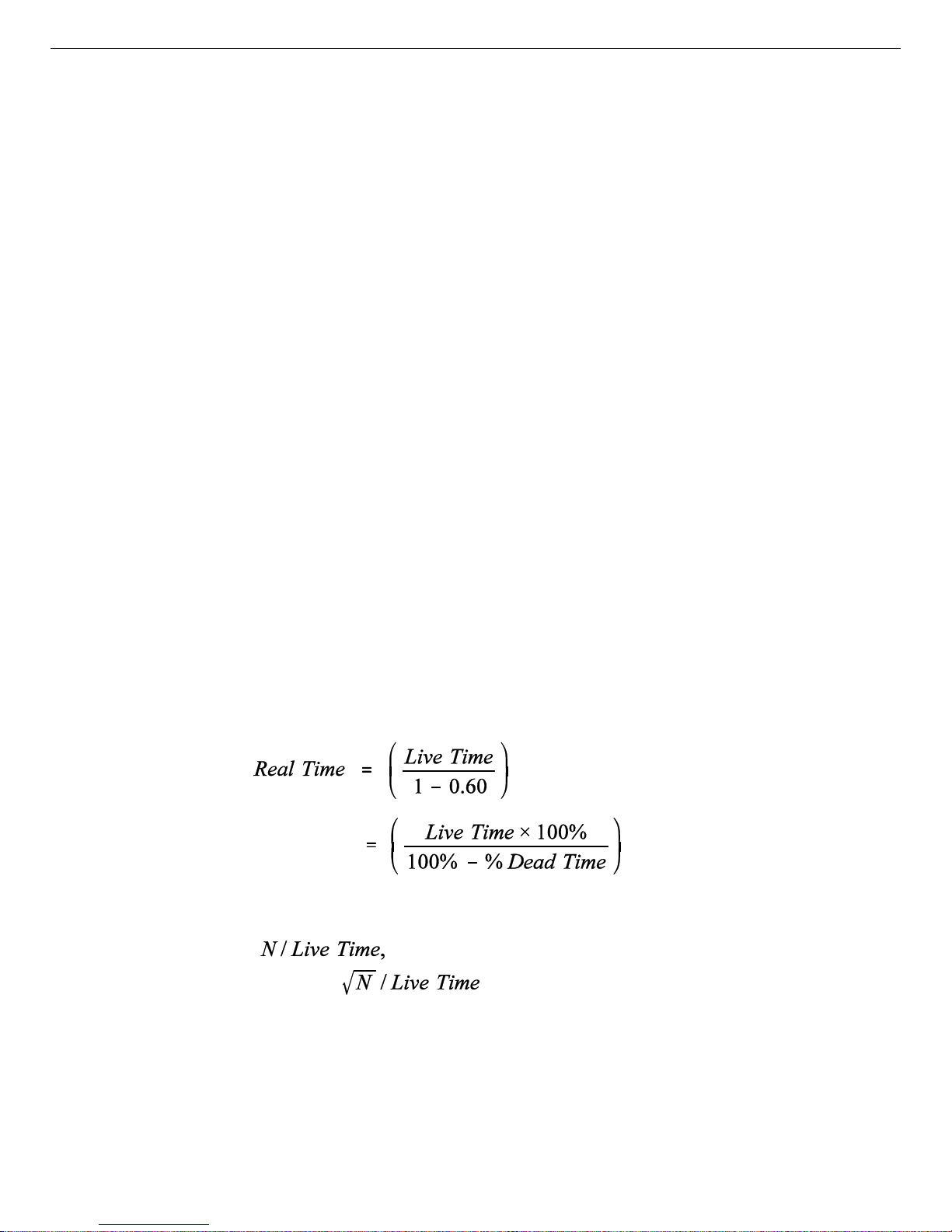
As an example, consider the case where the spectrometry amplifier and ADC are 60% dead
during the acquisition. the elapsed real time will be:
If the N counts in the gamma-ray peak in the spectrum are divided by the elapsed live time, the
resulting counting rate, is now corrected for dead-time losses. The standard
deviation in that counting rate is .
Unfortunately, extending the counting tim e to make up for losses due to system-busy results in
an incorrect result if the gamma-ray flux is changing as a function of time. If an isotope with a
very short half-life is placed in front of the detector, the spectrometer might start out with a very
high dead time, but the isotope will decay during the count and the dead time will be zero by the
end of the count. If the spectrometer extends the counting time to make up for the lost counts, it
9
Page 20

DSPEC Pro® Digital Gamma-Ray Spectrometer User’s Manual 794380D / 0914
will no longer be counting the same source as when the losses occurred. As a result, the number
of counts in the peak will not be correct.
6
When a supported ORTEC MCB operates in ZDT
mode, it adjusts for the dead-time losses by
taking very short acquisitions and applying a correction in real time — that is, as the data are
coming in — to the number of counts in the spectrum . This technique allows the gamma-ray flux
to change while the acquisition is in progress, yet the total counts recorded in each of the peaks
are correct. The resulting spectrum has no dead time at all — in ZDT mode, the data are corrected, not the acquisition time. Thus, the net counts in a peak are divided by the real time to determine the count rate.
ZDT mode has a unique feature in that it can store both the corrected spectrum and the uncorrected spectrum, or the corrected spectrum and the uncertainty spectrum. Therefore, supported
MCBs allow you to choose between three ZDT Mode settings on the ADC tab under MCB
Properties...: Off, NORM_CORR, and CORR_ERR.
Table 1 shows which spectra are collected in the three possible ZDT modes.
Table 1. ZDT Modes.
Mode Uncorrected
Off (ZDT Disabled)
NORM_CORR (ZDT–LTC Mode)
CORR_ERR (ZDT–ERR Mode)
Spectrum
Yes No No
Yes Yes No
No Yes Yes
ZDT Corrected
Spectrum
ZDT Error
Spectrum
1.6.1. Off — Uncorrected Spectrum Only
In this mode, only the uncorrected spectrum (live time and real tim e with dead-time losses) —
.SPC
also called the live-time-corrected or LTC spectrum — is collected and stored in the
file.
The LTC spectrum can be used to determine exactly how many pulses at any energy were processed by the spectrometer. The corrected spectrum gives the best estimate of the total counts
that would have been in the peak if the system were free of dead-time effects. The uncertainty
spectrum can be used to calculate the counting uncertainty, channel by channel, in the corrected
spectrum.
6
Patent number 6,327,549.
10
Page 21

794380D / 0914 1. INTRODUCTION
NOTE When the spectrometer is placed in ZDT mode, the throughput of the instrument is
reduced somewhat as extra processing must be done on the spectrum; therefore, if the
gamma-ray flux is not changing as a function of time, but absolute highest throughput
is desirable, you might wish to store only the LTC spectrum in the MCB memory.
1.6.2. NORM_CORR — ZDT and Uncorrected Spectra Stored
When the ZDT mode is set to NORM_CORR, the two spectra stored are the LTC spectrum and
the ZDT spectrum (corrected for the dead-time losses; real time only). Unfortunately, in the
analysis of the ZDT spectrum, the uncertainty of the measurement cannot be determined using
either spectrum.
NOTE This mode is not useful for quantitative analysis if the counting rate varies significantly
during the measurement time, particularly if the user desires an accurate counting rate
and standard deviation calculation. When you select the NORM_CORR mode, the
spectroscopy software ignores the ZDT spectrum and analyzes the LTC spectrum as it
would for the Off ZDT mode.
1.6.3. CORR_ERR — ZDT and Error Spectra Stored
In the CORR_ERR mode, the estimation of the statistical uncertainty is stored in place of the
LTC spectrum, and is referred to as the error spectrum (ERR). In this mode, the ZDT spectrum
is used to measure the counts in a peak, and the error spectrum is used to determine the uncertainty of the measurement made in the corrected spectrum.
For example, if the area of a peak is measured in the corrected spectrum by summing channels
1000 to 1100, the variance of the measurement can be determined by summing the counts in
channels 1000 to 1100 in the error spectrum. Or, shown another way, the counts in channel i can
be expressed as ± with a 1-sigma confidence limit, where N is the corrected spectral
data and V is the variance (error) spectral data.
The live time is set to the real time within the analysis engine during the analysis of ZDT
spectra.
7
A CORR_ERR spectrum is analyzed
as a regular spectrum most of the time, with a few
exceptions as listed below.
! To calculate the peak area uncertainty, the error spectrum is used. If the peak limits are
from L and H channels, then the background variance is calculated as:
7
Using our gamma-ray spectrum analysis software such as GammaVision® or ISOTOPIC.
11
Page 22
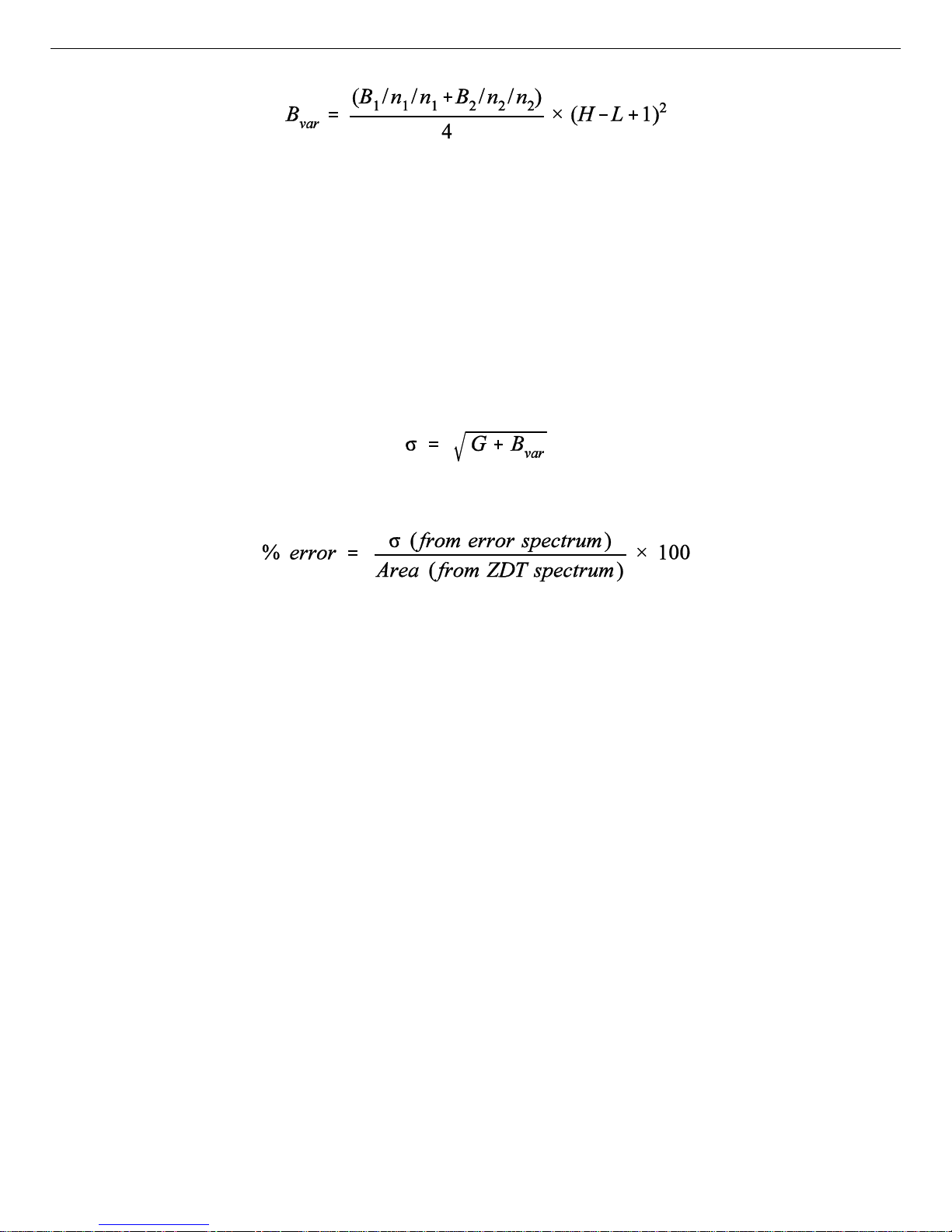
DSPEC Pro® Digital Gamma-Ray Spectrometer User’s Manual 794380D / 0914
where:
= sum of background counts for the channels adjacent to the peak start (low-
B
1
energy) channel L
= sum of background counts for the channels adjacent to the peak end (high-
B
2
energy) channel H
= the number of low background points (n1 = 1, 3, or 5) used
n
1
= the number of high background points (n2 = 1, 3, or 5) used
n
2
The peak area uncertainty is calculated from:
where G is the sum of counts, from the error spectrum, from channels L to H.
! In our WAN and ISOWAN analysis engines, the peak-fitting routine fits all the library
peaks as singlets to calculate the peak centroid, peak start and end channels, and peak
background. A linear background under the peak is assumed during the peak fitting
process.
! The error spectrum is always used to calculate the uncertainties of counts w henever
needed. For example, if peak deconvolution is needed, the error spectrum is used to find
the best fit for the peak background.
1.6.4. Choosing a ZDT Mode
When the counting rate is essentially constant during the time required to acquire the spectrum,
the standard mode — ZDT Off — is the preferred mode; only the uncorrected spectrum is collected and stored in the spectrum file. But, if the counting rate varies significantly during the
measurement time, the standard mode will not yield the proper dead-time-corrected counting
rate. This can be most easily understood by noting that the uncorrected mode compensates for
dead-time losses by extending the real counting time. Hence a sample containing both a shortlived high-activity isotope and a long-lifetime lower-activity isotope will experience very high
dead-time losses during the first few seconds of the measurement, as the short-lifetime isotope
decays rapidly. This high dead time will cause the counting time to be extended after the shortlived isotope has decayed to zero activity, and the system will count the low-activity isotope for
12
Page 23
794380D / 0914 1. INTRODUCTION
the extra time. Consequently, the average activity of the short-lived isotope will be underestimated.
If you anticipate significantly vary ing counting rates during the time taken to acquire the spectrum, the CORR_ERR ZDT mode should be used. The CORR_ERR mode corrects for deadtime losses over minuscule time intervals by adding counts to the ZDT spectrum in proportion to
the instantaneous ratio of real time to live time. Thus, the dead-time correction can correctly
track rapidly changing counting rates. The CORR_ERR mode should be used whenever the
counting rate might change significantly during the measurement time. In addition to the
rapidly-decaying isotope example above, the CORR_ERR mode should be used when monitoring cooling water flow from a nuclear reactor. The CORR_ERR mode accommodates brief
bursts of high-activity in the water flowing past the gamma-ray detector. Both the corrected and
error spectra are stored in the resulting spectrum file.
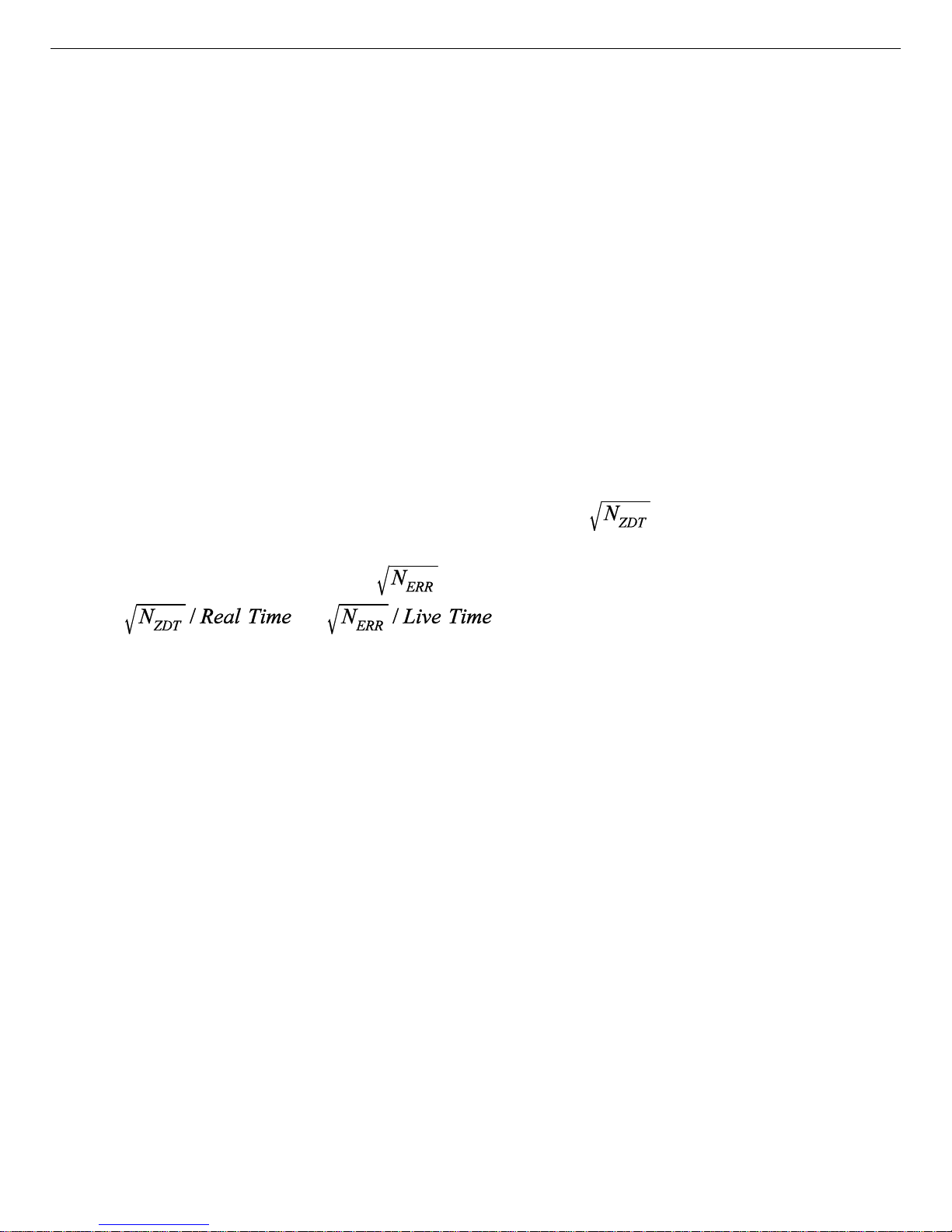
Note that the counts in the ZDT spectrum must be divided by the elapsed REA L time to compute
the dead-time corrected counting rate. It is important to note that the standard deviation in the
counts in a gamma-ray peak in the ZDT spectrum is not . Instead the standard devia-
N
ZDT
tion is obtained from the N
counts in the same peak ROI in the accompanying error spectrum.
ERR
The standard deviation in this case is . And the standard deviation in the computed counting rate, , is .
1.6.4.1. The NORM_CORR Diagnostic Mode
Why is there a NORM_CORR mode, and w hy should you avoid using it? This mode simultaneously collects the ZDT spectrum and the conventional uncorrected spectrum. It is useful for
demonstrating that the counts in the uncorrected spectrum divided by the live time is the same
counting rate as the counts in the ZDT spectrum divided by the real time, in the special case of
constant counting rate. Because the error spectrum is not collected in NORM_CORR mode, the
standard deviation in the ZDT counts cannot be calculated if the counting rate is varying. T he
spectroscopy software provides some protection for users if the ZDT-LTC mode is inadver-
tently selected. In this case, the software ignores the ZDT spectrum and presumes you intended
to use the uncorrected spectrum in a constant-counting-rate application.
1.6.4.2. To Summarize
Use the ZDT Off mode when the counting rate is expected to be constant during the time
taken to acquire the spectrum.
Use the ZDT CORR_ERR mode when the counting rate is expected to change or might
change significantly during the time required to acquire the spectrum.
13
Page 24
DSPEC Pro® Digital Gamma-Ray Spectrometer User’s Manual 794380D / 0914
Avoid using the NORM_CORR mode because the spectroscopy software w ill default to
analyzing the LTC spectrum and will ignore the ZDT spectrum.
1.6.4.3. More Information
! Visit our website or contact your ORTEC representative for more detailed information:
! Application note AN56, “Loss Free Counting with Uncertainty Analysis Using ORTEC’s
Innovative Zero Dead Time Technique,” (
http://www.ortec-online.com/pdf/an56.pdf
! General gamma spectroscopy technical papers (
reprints.htm#General
).
http://www.ortec-online.com/papers/
1.7. DSPEC Pro SMART-1 HPGe Detector Support
ORTEC’s SMART-1 Detector technology is a great advance in the operation of HPGe detectors
and is a major enhancement to data and chain-o f-custody integrity. The SMAR T-1 detector has a
high-voltage supply included, so the DSPEC Pro does not contain a high-voltage power supply.
For older detectors, a detector interface module (DIM) is used to supply the HV for the detector.
The SMART-1 detector monitors and reports on vital system functions. Also, its identification
serial number can be read by a controller such as the DSPEC Pro. For more security it can save
authentication codes written to it and report the code at a later time. The authentication code
value is replaced with every start command. At the end of the acquisition, both the serial number
and code are read and checked with the values at the start of the acquisition.
ORTEC SMART-1 HPGe detectors monitor the follow ing conditions:
! Preamplifier +/!24 and +/!12 V values (read-only)
! Preamplifier voltage out of range (read-only)
! Detector element temperature (read-only)
! Detector high voltage value (read-only)
! Detector high voltage state (on/off)
! Detector overload state (read-only)
! Detector high voltage shutdown state (read-only)
! Detector serial number (read-only)
! Detector authentication code (read/write)
14
Page 25

794380D / 0914 1. INTRODUCTION
1.7.1. SMART-1 HPGe Detector Construction
In the SMART-1 detector, the controller and high-voltage power supply are contained in a
single, small module and are permanently attached to the detector endcap. The cable is strainrelieved and sealed. This eliminates the possibility that the detector will suffer severe damage
from moisture leaking into high-voltage connectors. The controller can be positioned in any
convenient place. It does not interfere with shielding or other mounting hardware.
1.7.2. Using Older Detectors
For older detectors, a detector interface module (DIM) is used. The DIM is a compact size and
can be attached directly to the detector itself, keeping the length of the high-voltage cable to the
absolute minimum. The DIM is only needed for non-SMA R T-1 detector use.
The DSPEC Pro uses the following DIMs for support of non-SMART-1 detector systems:
! DIM-POSGE For any non-SMART-1, positive-bias, H PGe detector (includes short
leads with mating connectors for connecting to existing detector
cabling), +500 V to +5000 V.
! DIM-NEGGE For any non-SMART-1, negative-bias, HPGe detector (includes short
leads with mating connectors for connecting to existing detector
cabling), !500 V to !5000 V.
! DIM-POSNAI For any positive-bias NaI detector (includes short leads with mating
connectors for connecting to existing detector cabling), +100 V to
+1800 V.
! DIM-296 For any positive-bias NaI detector (with Model 296 ScintiPack tube
base/preamplifier/bias supply for NaI detectors w ith 14-pin, 10 stage
photo multiplier tubes), 0 V to 1200 kV.
1.7.3. How State of Health (SOH) is Monitored
The SMART-1 HPGe detector SOH function operates as follows: When the acquisition is
started, the DSPEC Pro clears all the bits of the SOH byte in the SMART-1 HPGe Detector
memory. During data acquisition, the SMART-1 HPGe Detector monitors the conditions listed
above. Should any of these values fall outside a specified range (even if they subsequently return
to normal), the relevant SOH bit is set. The bits stay set until cleared externally with the
Acquire/Clear command in MAESTRO; or the firmware commands CLEAR, CLEAR_ALL, or
CLEAR_HV_ HEALTH. At the end of the acquisition, the DSPEC Pro reads the SOH and if any
bit is set, displays a warning message. If no bits are set, no message is displayed; this means
15
Page 26

DSPEC Pro® Digital Gamma-Ray Spectrometer User’s Manual 794380D / 0914
there was no problem during the acquisition. The SOH status is saved with the spectral data in
.SPC
the
file as part of the QA data.
MAESTRO, Ga mmaVision, and other ORTEC programs can monitor the status of the SOH bit
for the current spectrum on the Status tab under Acquire/MCB Properties.... In addition, user-
developed programs may read and write the SOH register. Chapter 4 provides the commands for
reading and interpreting the SOH settings; see Appendix A for a table of SOH bit definitions.
1.8. Host Computer and Software Requirements
The DSPEC Pro is completely computer-controlled and can be operated with any suitable
ORTEC C
(A65-BW), communicating via the supplied version of C
MAESTRO runs under Microsoft
ONNECTIONS software, including the supplied MAESTRO MCA Emulation Software
ONNECTIONS. The current version of
®
Windows 8, 7, XP Professional SP3.
1.9. About this Manual
This manual describes the DSPEC Pro, tells how to connect it in a complete spectroscopy system, gives instructions on configuring the hardware settings (such as high voltage, presets, and
gain), and supplies the hardware commands and responses. Complete details on using the control software are in the accompanying MAESTRO Software User’s Manual as well as the man-
uals for GammaVision
®
, Renaissance®, ISOTOPIC, and our other spectroscopy software.
8
8
For the purposes of this manual, when we refer to MAESTRO, we mean the ORTEC MCA emulator/analysis
application you are using (e.g., MAESTRO, GammaVision, ISOTOPIC).
16
Page 27
2.1. The DSPEC Pro
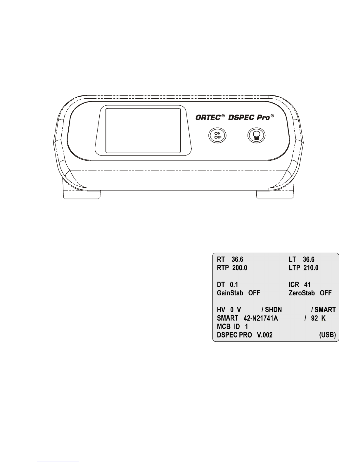
2.1.1. Front Panel
Figure 5 shows the DSPEC Pro front panel.
2. GETTING STARTED
Figure 5. DSPEC Pro Front Panel.
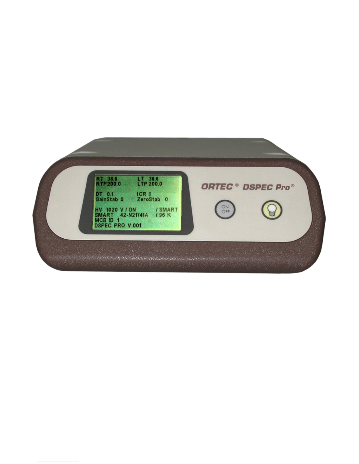
2.1.1.1. The Display
The DSPEC Pro has a 240 × 160-pixel LCD
display for viewing counting settings and status,
high-voltage setting and status, stabilizer settings,
SMART-1 detector status, and shutdown mode.
When connected to a computer via the USB connector, an indicator is displayed in the lower right.
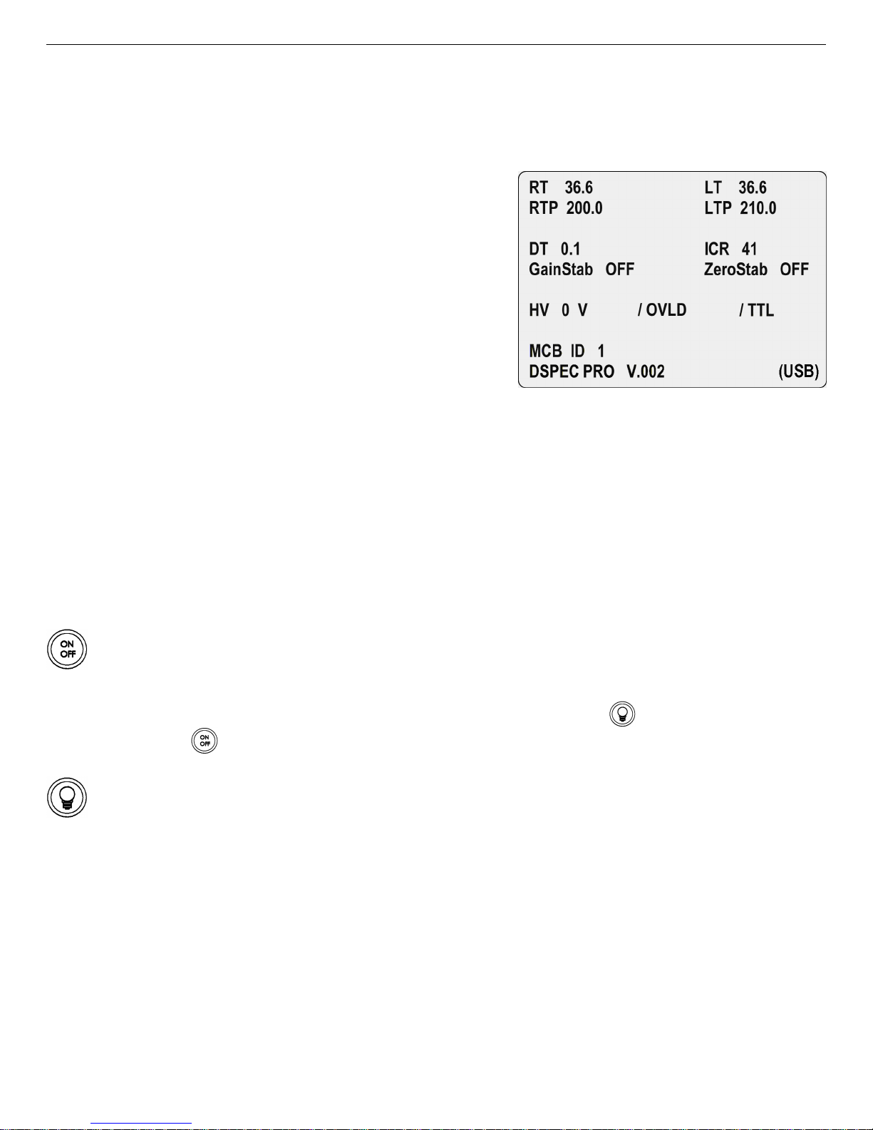
Figure 6 shows the layout of display for a DSPEC
Pro with a SMART-1 detector attached.
RT, RTP, LT, and LTP are, respectively, the
actual real time, real-time preset, live time, and
live-time preset.
Figure 6. The DSPEC Pro Display
Showing Presence of a SMART-1
Detector.
DT and ICR are the dead time, in percent, and input count rate, in counts per second (CPS).
GainStab and ZeroStab show the current setting for the gain and zero stabilizers, respectively.
17
Page 28
DSPEC Pro® Digital Gamma-Ray Spectrometer User’s Manual 794380D / 0914
The next line shows the current high-voltage setting (HV); the current high-voltage status (ON,
OFF, SHDN [shutdown], or OVLD [overload]); and the shutdown mode (TTL, ORTEC, or
SMART).
If a SMART-1 detector is attached, the DSPEC
Pro displays a line immediately beneath the highvoltage line; this line is blank for other detector
types (compare Figs. 6 and 7). On the left are the
word SMART and the first 10 characters of the
SMART-1 detector’s serial num ber. This is the
same value returned by the SHOW_DET_SNU M
command. On the right is the detector temperature in kelvins.
Figure 7. The DSPEC Pro Display for a
The next line shows the ID number for this
Non-SMART-1 Detector.
DSPEC Pro as set by the MCB Configuration
program and displayed in the Master Instru-
ment List (see the MAESTRO user manual for more information on the MCB Configuration program and the Master Instrument List).
The last line on the display gives the firmware version for this DSPEC Pro.
2.1.1.2. Controls
ON/OFF To power up the DSPEC Pro, press ON/OFF. It takes up to 20 seconds for
the display to appear. To turn off the instrume nt, press ON/OFF. The DSPEC Pro is
designed to avoid accidental power-down so acquisition isn’t interrupted. The display
will ask you to confirm shutdown: press the backlight button ( ) to power down or
ON/OFF ( ) to ignore the shutdown command.
Backlight button Press to turn the display backlight on and off. We recomme nd use of
the backlight for easy viewing.
2.1.2. Rear Panel
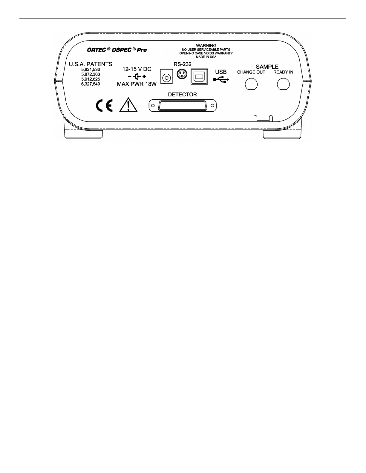
Figure 8 shows the rear panel.
! 12–15 V DC Connects to the accompanying ac/dc power adapter.
! DETECTOR Attach to the SMART-1 HPGe detector or DIM cable.
18
Page 29
794380D / 0914 2. GETTING STARTED
Figure 8. DSPEC Pro Rear Panel.
! USB Connects to the host computer. Note that you can connect to and disconnect from
the computer without restarting Window s or MAESTRO. (How ever, if you disconnect
with MAESTRO running, an error message will be generated. When you reconnect to the
computer, you must reselect this MCA from MAESTRO’s detector droplist, as described
in the MAESTRO user manual.)
2.2. Software and Hardware Installation
Installing the DSPEC Pro and the MAESTRO MCA Emulation Software takes just four easy
steps. You must have Administrator access in Windows to install MAESTRO.
For easiest installation do not connect the DSPEC Pro to your computer until MAESTRO has
been installed.
1) Install the accompanying C
USB-based instruments family on the install wizard’s Instrument Setup page.
2) Install the accompanying MAESTRO MCA Emulation Software (A65-BW ).
3) Connect the DSPEC Pro to the USB port on the computer.
4) Run the MCB Configuration program to build a list of available ORTEC MCBs.
ONNECTIONS Driver Update Kit (P/N 797230), selecting the
19
Page 30
DSPEC Pro® Digital Gamma-Ray Spectrometer User’s Manual 794380D / 0914
2.2.1. Step 1: Install the CONNECTIONS Driver Update
The first step is to install the C
ONNECTIONS Driver Update Kit (P/N 797230) according to its
instruction sheet. This software must be installed before MAESTRO can be installed. The update
kit’s instructions tell how to install C
ONNECTIONS, enable/disable the drivers for your ORTEC
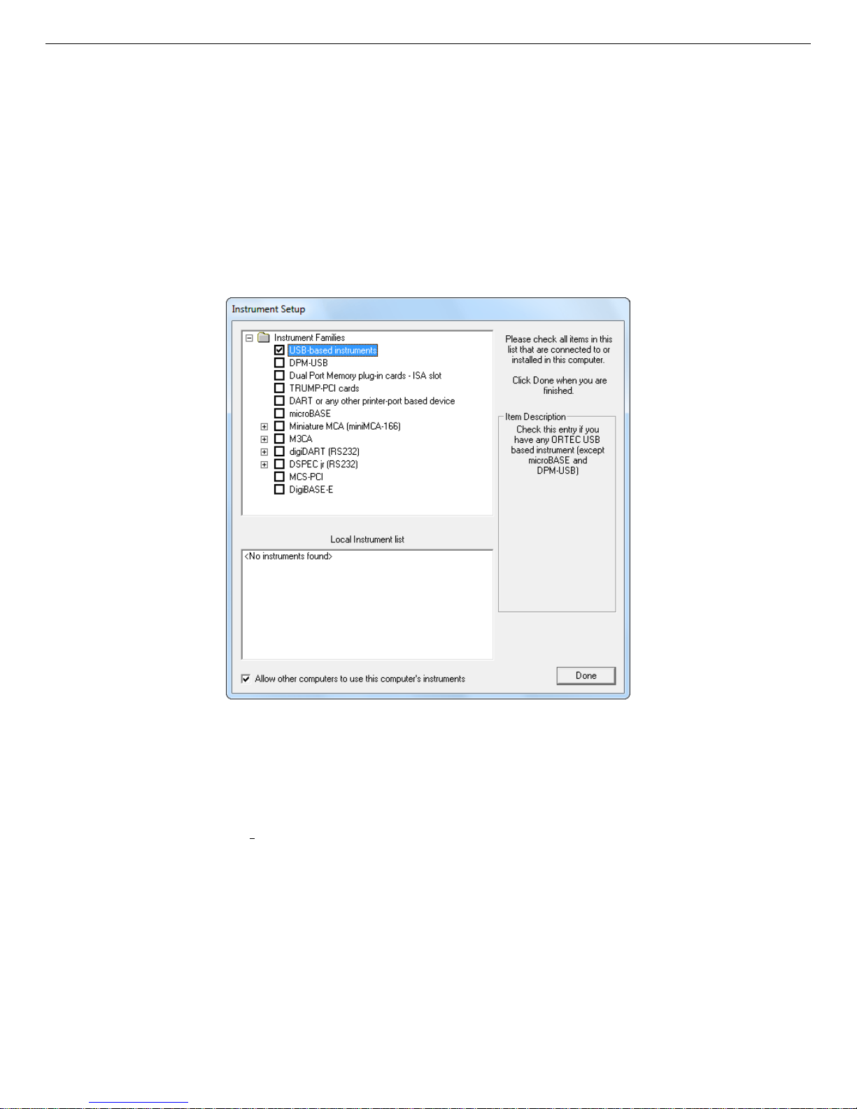
MCB(s), and share ORTEC instruments across a network. On the Instrume nt Families page, be
sure to mark the USB-based instruments checkbox, as shown in Fig.9. Otherwise the DSPEC
Pro will not be able to communicate with the computer and MAESTRO software. At the end
of installation, you will be directed to restart the computer.
Figure 9. Choose ‘USB-based instruments’.
If you also have other types of MCBs attached to this computer, refer to the installation instructions in the corresponding hardware manuals. Note that you can install device drivers for other
types of instruments later,
as described in the CONNECTIONS Driver Update Kit instructions.
2.2.2. Step 2: Install MAESTRO
Install MAESTRO according to the instructions in its User Manual.
20
Page 31

794380D / 0914 2. GETTING STARTED
2.2.3. Step 3: Connect the DSPEC Pro to the Computer
1) With the computer powered on, connect the DSPEC Pro to the computer’s USB port.
2) Windows will indicate that the DSPEC Pro has been detected. In Windows 8 and 7, the
driver will install without a wizard. In XP, the new hardware installation wizard will open.
Click Next, indicate you do not wish to connect to the internet or the Microsoft website to
locate the driver, choose the “automatically locate driver” option, and follow the remaining
prompts to completion. When this operation is complete, y ou are ready to run the MCB
Configuration program so that MAESTRO and other C
ONNECTIONS software can recognize
the DSPEC Pro.
2.2.4. Step 4: Run MCB Configur ation to Communicate With Your MCBs
IMPORTANT
This is an abbreviated discussion of the operation and use of the MCB Configuration program.
We strongly recom mend that you read the instructions for the C
ONNECTIONS Driver Update Kit
for complete details on the com mand line arguments that change how the program searches for
MCBs, customizing MCB ID Numbers and Descriptions, changing your Windows firewall
settings to allow MCB access across a network, enabling additional device drivers, and
troubleshooting.
1) Make sure the DSPEC Pro is connected and powered on.
2) Connect and power on all other local and network ORTEC instruments that you wish to use,
as well as their associated PCs. Otherwise, the MCB Configuration program will not detect
them during installation. Any instruments not detected can be configured at a later time.
mcb
3) To start the software, type
in the “Search programs and files” box on the Windows
Start menu, then click the MCB Configuration search result; or open the Windows Start
menu and click MAESTRO, then MCB Configuration. The MCB Configuration program
will locate all of the powered-on ORTEC MCBs on the local computer and the network, and
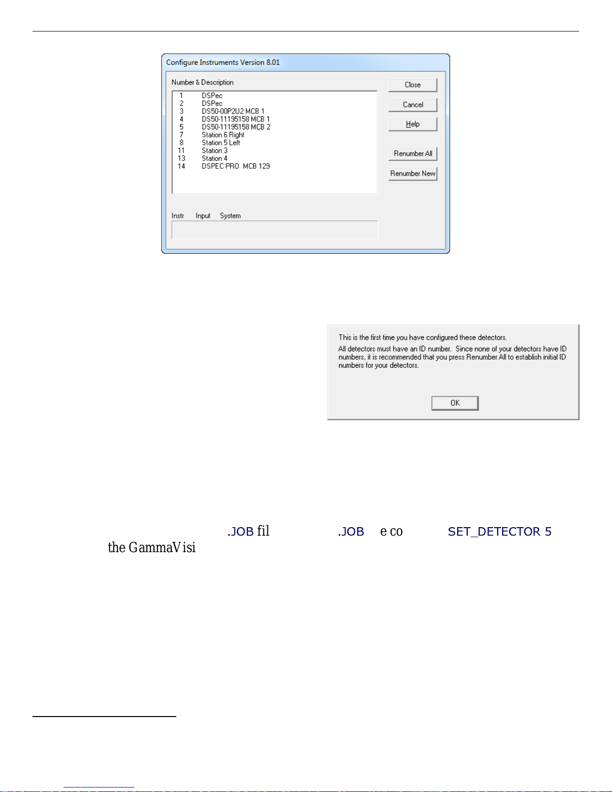
display the list of instruments found (the M aster Instrument List; Fig. 10). If you wish, you
may enter customized instrument ID numbers and descriptions (Section 2.2.4.2). When you
close the dialog, any changes you have made to an ID number or description will be w r itten
back to the corresponding MCB.
21
Page 32
DSPEC Pro® Digital Gamma-Ray Spectrometer User’s Manual 794380D / 0914
Figure 10. MCB Numbering and Descriptions.
2.2.4.1. Configuring a New Instrument
The first time a new instrument is detected, the
dialog shown in Fig. 11 will remind you that
all new instruments must be assigned a unique,
9
non-zero ID number.
Click OK. You can
either manually change the ID Number and
Description as described in the next subsection,
or you can click the Renumber New button
to renumber only the new instruments.
Figure 11. New Instruments Must Have a NonZero ID Number.
NOTE We strongly recommend not using the Renumber All button. In addition, we strongly
recommend not renumbering MCBs that “belong” to other users, as this could affect
the interaction between their MCBs and their ORTEC software, for instance, if they
control their MCBs with
.JOB
files (e.g., the
.JOB
file command
SET_DETECTOR 5
), or
use the GammaVision or ISOTOPIC spectroscopy applications. See also the NOTE
FOR MULTIPLE USERS ON A NETWORK in the next section.
2.2.4.2. Customizing ID Numbers and Descriptions
If you wish, you can change the instrument ID Num bers and Descriptions by double-clicking an
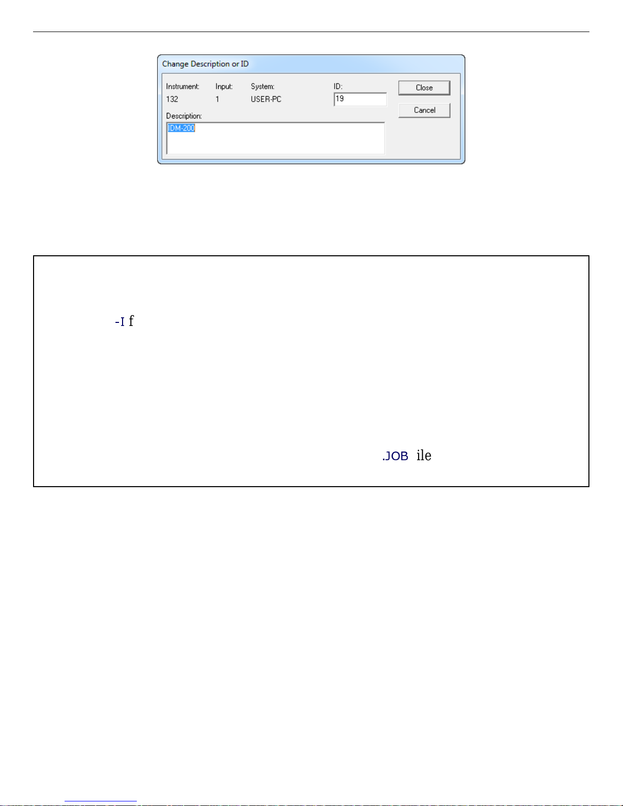
instrument entry in the Configure Instruments dialog. This will open the Change Description or
ID dialog (Fig. 12). It shows the physical MCB location (read-only), and allows you to change
the ID Number and Description.
9
If this is a first-time installation of ORTEC products, all your instruments will be “new.”
22
Page 33
794380D / 0914 2. GETTING STARTED
Figure 12. Change MCB Number or Description.
Make the desired changes and click Close. Any changes you have made to an ID number or
description will then be written back to the corresponding MCB.
NOTE FOR MULTIPLE USERS ON A NETWORK
There are two ways to reduce the chance that other users will renumber your MCBs:
-I
! Add the
TIONS Driver Update Kit instructions. T his will allow y ou to assign whatever ID Num bers
flag to their MCB Configuration command line, as described in the CONNEC-
you wish, regardless of the numbers assigned by other users on your network. (Ideally,
everyone using ORTEC instruments on your network should make this change.)
! To prevent others from renumbering your MCBs (or performing any other actions except
read-only viewing), password-lock your MCBs with the MAESTRO Lock/Unlock Detector
command. If you lock a detector that will be controlled by a JOB stream, remember to
.JOB
include the proper password-unlock comm ands in your
file (see the MAESTRO user
manual).
If a modified description has already been applied to a particular instrument, you can restore the
default description by deleting the entry in the Description field and re-running MCB Configuration. After MCB Configuration runs, the default description will be displayed.
2.2.5. Attaching More Than One DSPEC Pro to the Computer
Once the drivers have been installed for one DSPEC Pro, adding subsequent units is simple.
REMINDER Be sure to run MCB Configuration any time you add new DSPEC Pros (or other
ORTEC MCBs) to your system, or when you move an instrument from one USB
port to another.
23
Page 34
DSPEC Pro® Digital Gamma-Ray Spectrometer User’s Manual 794380D / 0914
2.2.6. Connecting to and Disconnecting from the Computer
The USB connection allows you to connect DSPEC Pros to and disconnect them from a USB
port without shutting down the computer or USB hub. Note that if MAESTRO is running when
you disconnect the DSPEC Pro, you will see a “detector not responding” message on the status
line at the bottom of the MAESTRO window. When you reconnect the DSPEC Pro to the computer, you will have to reselect it from the detector droplist on the Toolbar.
2.3. DSPEC Pro MCB Properties in MAESTRO
This section discusses the hardware setup dialog you will see within MAESTRO and all other
ORTEC C
MCB Properties.... The DSPEC Pro is completely software controlled; the MCB Properties
dialog contains all of the instrument controls including ADC setup parameters, acquisition presets, amplifier gain adjustments, pole-zero controls, and access to the InSight Virtual Oscilloscope. Just move from tab to tab and set your hardware parame ters, then click Close — it’s that
easy.
ONNECTIONS software (e.g., GammaVision, ISOTOPIC) when you click Acquire/
Note that as you enter characters in the data-entry fields, the characters will be underlined
you move to another field or until 5 seconds have lapsed since a character w a s last entered.
During the time the entry is underlined, no othe r program or computer on the network can
modify this value.
2.3.1. Amplifier
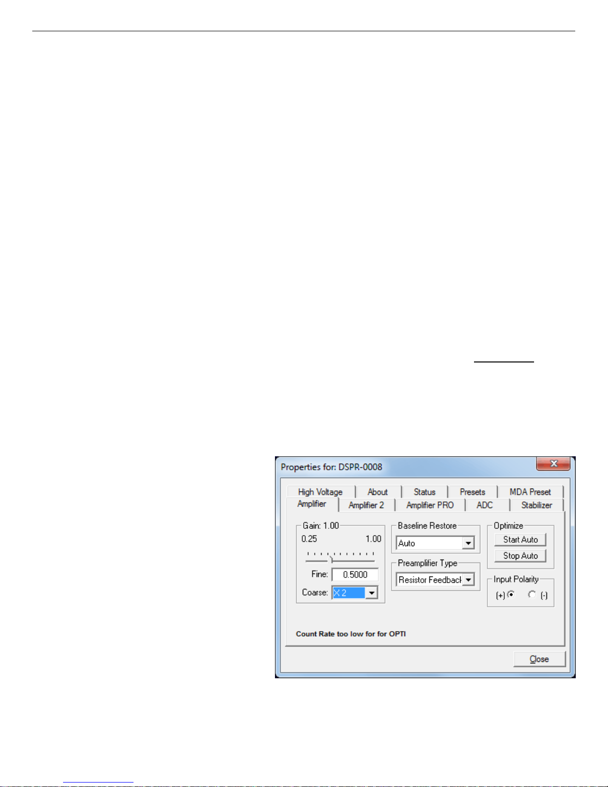
Figure 13 shows the Amplifier tab.
This tab contains the controls for
Gain, Baseline Restore, Preamplifier Type, Input Polarity, and
Optimize.
NOTE Be sure that all of the
controls on the tabs have
been set before clicking
the Start Auto (optimize)
button. The changes you
make on most property
tabs take place immediately.
There is no cancel or undo
Figure 13. DSPEC Pro Amplifier Tab.
for these dialogs.
until
24
Page 35

794380D / 0914 2. GETTING STARTED
Gain — Set the amplifier coarse gain by choosing from the Coarse droplist, then adjust the Fine
gain with the horizontal slider bar or the edit box, in the range of 0.45 to 1.00. The resulting
effective gain is shown at the top of the Gain section. The two controls used together cover the
entire range of amplification from 0.45 to 32.
Input Polarity — These buttons select the preamplifier input signal polarity for the signal from
the detector. Normally, GEM (p-type) detectors have a positive signal and GMX (n-type) have a
negative signal.
Baseline Restore — This is used to return the baseline of the pulses to the true zero between
incoming pulses. This improves the resolution by removing low frequency noise from dc shifts
or mains power ac pickup. The baseline settings control the time constant of the circuit that
4
returns the baseline to zero. There are three fixed choices (Auto,
Fast, and Slow). The fast setting is used for high count rates, the slow for low count rates. Auto adjusts the time constant as
appropriate for the input count rate. The settings (Auto, Fast, or Slow) are saved in the DSPEC
Pro even when the power is off. The time constant can be ma nually set on the InSight display
(see the discussion beginning on page 27).
You can view the time when the baseline restorer is active on the InSight display as a Mark
region (see the discussion on Marks, p. 29). In the automatic mode, the current value is shown
on the InSight sidebar (Fig. 15). For a low-count-rate system, the value will remain at about 90.
Preamplifier Type — Choose Transistor Reset or Resistive Feedback. Your choice will
depend on the preamplifier supplied with the germanium detector being used.
3
Optimize — The DSPEC Pro is equipped with both automatic pole-zero logic
10
flattop logic.
The Start Auto (optimize) button uses these features to automatically choose the
and automatic
best pole-zero and flattop tilt settings. Note that if you select Transistor Reset as the preamplifier type, the optimization routine does not perform the pole-zero.
During optimization, pole zeroes are performed for several rise-time values, and the DSPEC Pro
cycles through all the rise time values for the determination of the optimum tilt values. As all of
the values for all the combinations are maintained in the DSPEC Pro, you do not have to repeat
optimization for each possible rise time.
Optimization requires a source with sufficient activity to register between 800 cps and 5000 cps.
Arrange the detector in its final configuration. Unmark the LFR checkbox on the Amplifier PRO
tab (you cannot optimize with LFR mode enabled; see Section 2.3.3), turn on the HV so the
instrument is processing pulses, then place the source on or near the detector endcap. A count
10
Patent number 5,821,533.
25
Page 36
DSPEC Pro® Digital Gamma-Ray Spectrometer User’s Manual 794380D / 0914
rate guidance message on the lower-left of the Amplifier page will help you position the source
to deliver the correct count rate for optimization. You may also right-click in the spectrum
window and select Input Count Rate from the context menu to view the count-rate meter. The
Start Auto optimization button will rema in disabled (gra y) until the count rate is suitable. Click
it to start.
A series of short beeps indicates optimization is in progress. When optimizing is complete, the
beeping will stop. The process can take from 1 to 10 minutes, depending on count rate, but typically takes 5 minutes.
NOTE As with any system, the DSPEC Pro should be optimized any time the detector is
replaced or the Flattop Width is changed.
The effect of optimization on the pulse can be seen in the InSight mode, on the Amplifier 2 tab.
Note, however, that if the settings were close to proper adjustment before starting optimization,
the pulse shape may not change enough for you to see. (In this situation, you also may not notice
a change in the shape of the spectrum peaks.) The most visible effect of incorrect settings is
high- or low-side peak tailing or poor resolution.
2.3.2. Amplifier 2
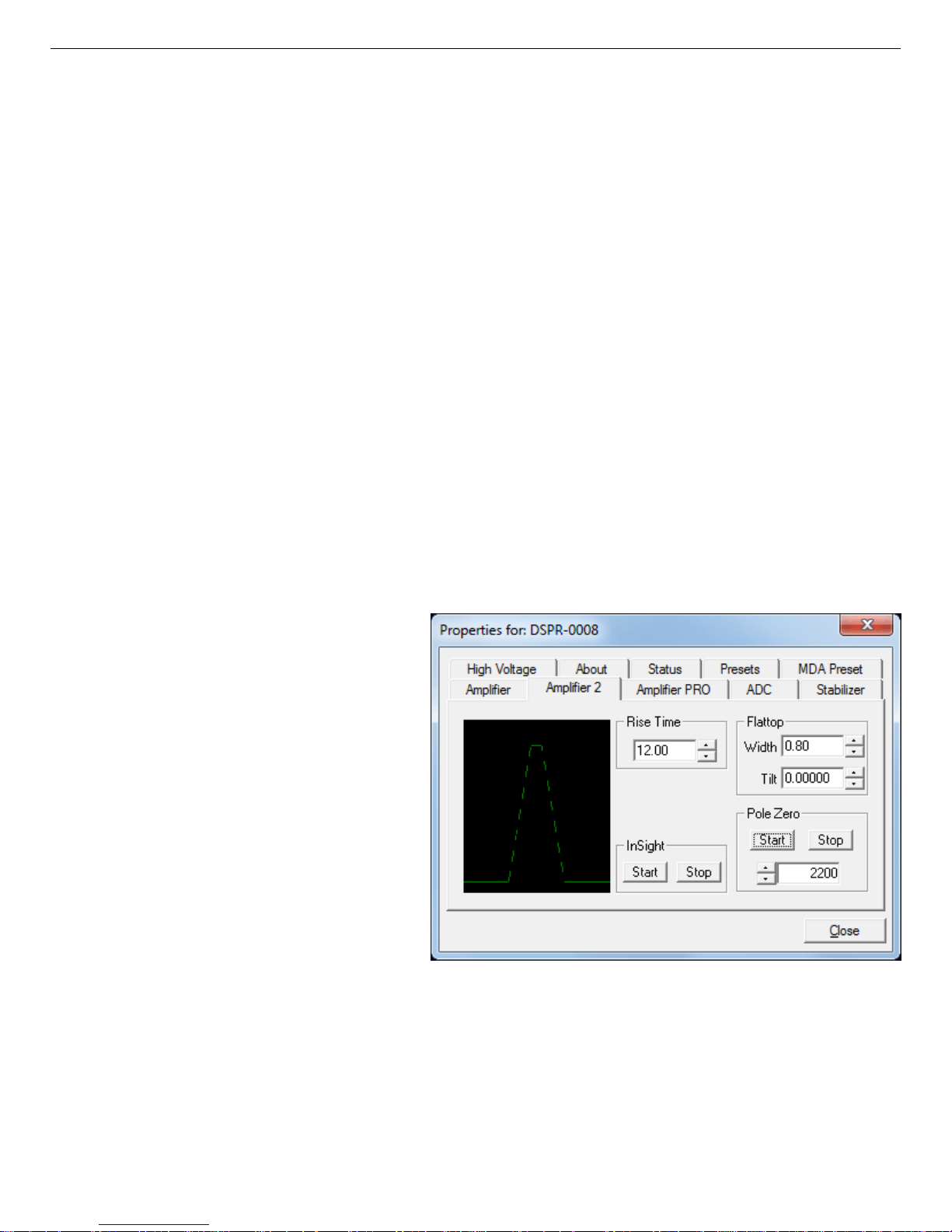
Figure 14 shows the Amplifier 2
tab, which accesses the advanced
shaping controls including the
InSight Virtual Oscilloscope mode.
The many choices of Rise Time let
you precisely control the tradeoff
between resolution and throughput;
see Section 2.4. This setting affects
both the rise and fall times, so
changing it spreads or narrows the
quasi-trapezoid symmetrically.
Use the up/down arrows to set the
Rise Time from 0.8 to 23.0 µs.
Figure 14. DSPEC Pro Amplifier 2 Tab.
Once the unit has been optimized
according to Section 2.3.1, you can use any Rise Time without having to re-optimize.
The value of the rise time parameter in the DSPEC Pro is roughly equivalent to twice the integration time set on a conventional analog spectroscopy amplifier. Thus, a DSPEC Pro value
of 12 µs corresponds to 6 µs in a conventional amplifier. Starting with the nominal value of 12.0,
26
Page 37
794380D / 0914 2. GETTING STARTED
you should increase values of the rise time for better resolution for expected lower count rates,
or when unusually high count rates are anticipated, reduce the rise time for higher throughput
with somewhat worse resolution.
The Flattop controls adjust the top of the quasi-trapezoid. The Width adjusts the extent of the
flattop (from 0.3 to 2.4 µs). The Tilt adjustment varies the “flatness” of this section slightly. The
Tilt can be positive or negative. Choosing a positive value results in a flattop that slopes downward; choosing a negative value gives an upward slope. Alternatively, the optimize feature on
the Amplifier tab can set the tilt value automa tically. This automatic value is normally the best
for resolution, but it can be changed on this dialog and in the InSight mode to accommodate
particular throughput/resolution tradeoffs. The optimize feature also automatically adjusts the
pole-zero setting.
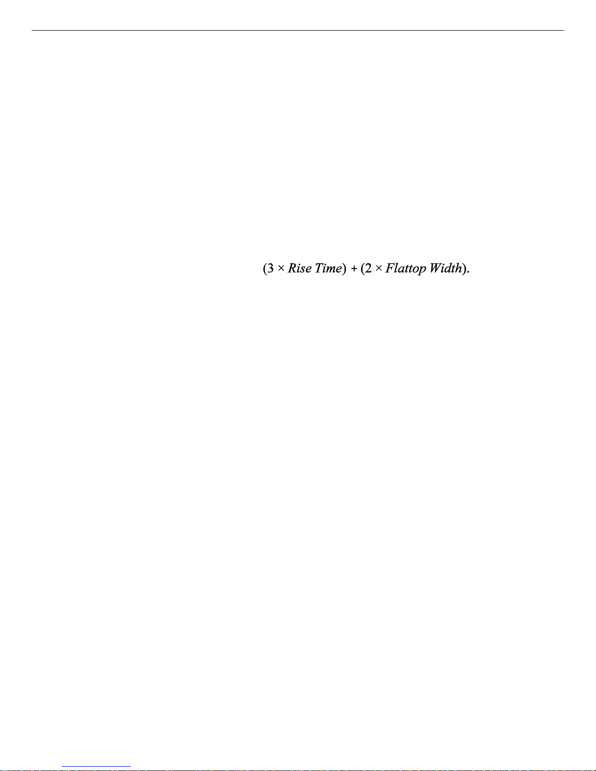
The dead time per pulse is approximately
In the Pole Zero section, the Start button performs a pole zero at the specified rise time and
other shaping values. Unlike the optimize feature, it performs a pole zero for only the one rise
time. The pole-zero Stop button aborts the pole zero, and is norm ally not used.
For the more advanced user, the InSight mode lets you directly view all the parameters and
adjust them interactively while collecting live data. To access the InSight mode, go to the
Insight section on the Amplifier 2 tab and click Start. The InSight mode is discussed in more
detail in the following section. When you are satisfied with the settings, you are ready to acquire
data. Once data acquisition is underway, you may wish to return to MCB Properties... and click
the Insight section’s Start button to adjust the shaping parameters interactively with a “live”
waveform showing the actual pulse shape, or j ust to verify that all is well.
2.3.2.1. InSight Mode
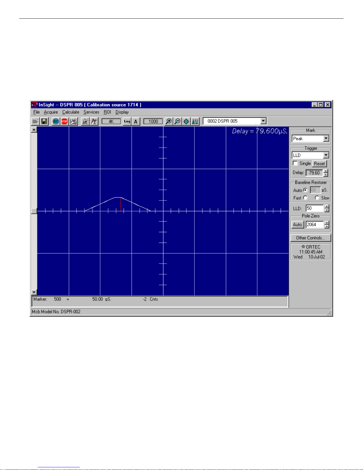
The InSight display (Fig. 15) shows the actual sample d waveform in the digital processing units
on a reference graticule. The Properties dialog remains active and can be used to change settings
while viewing the pulses.
As none of the traditional analog signals are available in the DSPEC Pro, this m ode is the only
way to display the equivalent amplifier output pulse. Note that at the bottom of the window the
marker channel is displayed in units of time.
To exit the InSight mode and return to the PHA display, press <Esc> or go to the Insight section
on the Amplifier 2 tab and click Stop. The PHA mode is set to STOP when you enter the InSight
mode.
27
Page 38
DSPEC Pro® Digital Gamma-Ray Spectrometer User’s Manual 794380D / 0914
The Status Sidebar changes from the PHA mode controls to the InSight controls for adjusting
the peak display. On the left is a vertical scrollbar for adjusting the vertical offset of the waveform. The value of the offset is shown on the display. Double-clicking the mouse in the scrollbar
will set the vertical offset to the vertical value of the channel at the marker position. This lets
you conveniently zoom in on a particular part of the waveform (such as the tail for pole-zeroing).
Figure 15. DSPEC Pro InSight Mode.
In the Auto trigger mode, the display is updated every time a new pulse exceeds the trigger
level. To keep a single pulse displayed, select Single. Click Reset to refresh the display to see
the next pulse. There will usually be one or two pulses in the “pipeline” that will be displayed
before any change entered will be seen. If the trigger is turned off, the display will be redrawn
periodically, even if no pulse is there.
The Delay setting is the time delay between the pulse shown on the display and the trigger level
crossing. The value of the time delay is shown on the display.
28
Page 39
794380D / 0914 2. GETTING STARTED
Just as for the PHA mode display, the vertical scale can be adjusted with the vertical adjustments. The display can be set to Log mode, but the peak shapes do not have a familiar shape in
this display. The Auto mode will adjust the vertical scale for each pulse. The pulse is shown
before the amplifier gain has been applied, so the relation between channel num ber and pulse
height is not fixed.
The horizontal scale extends from 16 to 256 channels. The display is expanded around the
marker position which m eans that in some cases the peak will disappear from the display when it
is expanded.
The display can be switched from the DSPEC Pro to another detector or the buffer. In this case
the other detector will be shown in the mode selected for it. The buffer will always be shown in
PHA mode. The display will return to the InSight mode when you return to the first DSPEC Pro.
If you exit the program with the DSPEC Pro in InSight mode, it will be in InSight mode on the
next startup.
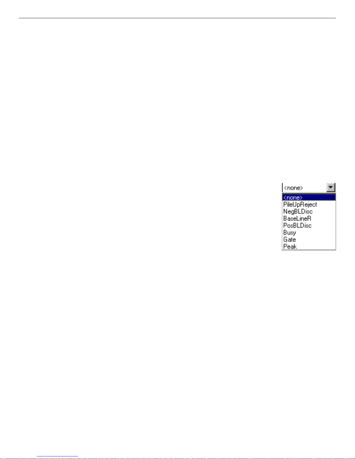
The display can include a Mark to indicate one of the other signals shown
in Fig. 16. The Mark is a solid-color region displayed similarly to that of an
ROI in the spectrum. This Mark can be used to set the tim ing for the gate
pulse. It can also be used to set the shaping times and flattop parameters to
get the best performance. For example, suppose you want to get the best
resolution at the highest throughput possible. By viewing the pulses and the
pileup reject marker, you can increase or decrease the rise time to obtain a
minimum of pileup reject pulses.
Figure 16. Mark
Display Selection.
Mark Types
For the Mark, choose either “points” or “f illed” (to the zero line) display. This is controlled by
the selection in the Display/Preferences menu item. T hat choice does not affect the PHA mode
choice. The colors are the same as for the PHA mode.
None No channels are marked in the display.
PileUpReject The region marked indicates when the PUR circuit has detected pileup and
is rejecting the marked pulses.
NegBLDisc This shows when the negative baseline discriminator has been triggered.
Typically this signal only marks the TRP reset pulse. The signal is used
internally in the live-time correction, baseline restoration, and pile-up
rejection circuits.
29
Page 40

DSPEC Pro® Digital Gamma-Ray Spectrometer User’s Manual 794380D / 0914
BaseLineR This shows when the baseline restorer is actively restoring the baseline.
PosBLDisc This shows when the positive baseline discriminator has been triggered. The
signal is used internally in the live-time correction, baseline restoration, and
pile-up rejection circuits.
Busy When the DSPEC Pro busy signal is active, Busy shows in the Mark box. It
represents the dead time.
Gate This shows when the gate signal is present on the gate input connector. If
the Gate mode on the ADC tab (see Fig. 18) is set to Off, then all regions
are marked. If the mode is set to Coincidence, then the marked region must
overlap the pulse peak (that is, must start before the beginning of the flattop
and stop after the end of the flattop) for the pulse to be counted. If the mode
is set to Anticoincidence, then the marked region will show the pulses that
are accepted. That is, the rejected peaks will not be marked. Simply put, in
all modes the accepted peaks are marked.
Peak This is the peak detect pulse. It indicates when the peak detect circuit has
detected a valid pulse. The Mark occurs about 1.5 µs after the pulse
maximum on the display.
On the lower right of the InSight display are the shaping parameter controls. The controls are
split into two groups, and the other controls... button switches between them .
One group includes Rise Time, Flattop, Tilt, and the Optimize button. The Rise Time value is
for both the rise and fall times; thus, changing the rise tim e has the effect of spreading or
narrowing the quasi-trapezoid symmetrically.
The Flattop controls adjust the top of the quasi-trapezoid. The Width adjusts the extent of the
flattop (from 0.3 to 2.4 µs). The Tilt adjustment varies the “flatness” of this section slightly. The
Tilt can be positive or negative. Choosing a positive value results in a flattop that slopes downward; choosing a negative value gives an upward slope. Alternatively, Optimize can set the tilt
value automatically. This value is normally the best for resolution, but it can be changed on this
dialog and in the InSight mode to accommodate particular throughput/resolution tradeoffs. The
Optimize button also automatically adjusts the pole-zero setting.
2.3.3. Amplifier PRO
This tab (Fig. 17) contains the controls for the Low Frequency Rejector (LFR) filter, Resolution Enhancer, and Enhanced Throughput Mode. To enable a particular feature, mark the cor-
30
Page 41
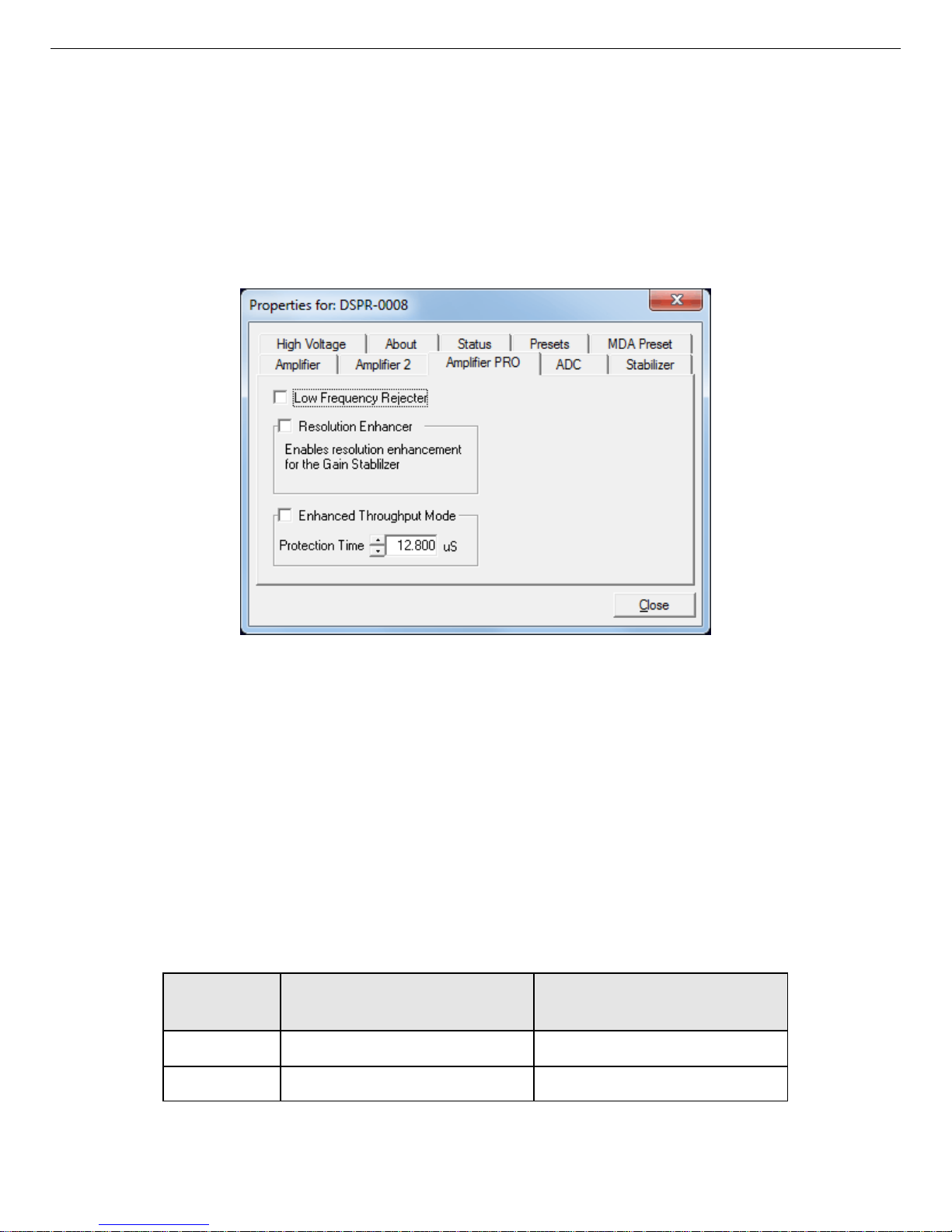
794380D / 0914 2. GETTING STARTED
responding checkbox. Any or all of these features can be used at one time, however, the LFR
and Enhanced Throughput modes must be set up before the Resolution Enhancer is configured,
as discussed below.
Note that once an MCB is “trained” for the Resolution Enhancer (see the following section),
it must be “retrained” if any settings are changed that can affect peak shape or position (e.g.,
bias, gain, rise time, flattop, PZ).
Figure 17. DSPEC Pro Amplifier PRO Tab.
Low Frequency Rejector — This feature is discussed in detail in Section 1.4.
! The DSPEC Pro cannot optimize or pole-zero in LFR mode. Optimize or PZ with the
filter off, then turn it back on for data collection.
! LFR mode affects the available range of protection times in Enhanced Throughput
Mode, as discussed in the next paragraph.
Enhanced Throughput Mode — See Section 1.2 for a discussion of this feature. The valid
Protection Time settings, in 25 ns increments, range as follows:
LFR Mode Highest Throughput
(minimum Protection Time)
Off (Rise Time + flattop) (2 × Rise Time + Flattop)
On (3 × Rise Time + 2 × Flattop) (6 × Rise Time + 3 × Flattop)
Lowest Throughput
(maximum Protection Time)
31
Page 42

DSPEC Pro® Digital Gamma-Ray Spectrometer User’s Manual 794380D / 0914
Turning on this feature automatically sets the minimum protection time (highest throughput rate)
based on your current Rise Time and Flattop settings, however, you can adjust this value at any
time. Each time you change the rise time or flattop, the DSPEC Pro will automatically set itself
to the new minimum protection time.
2.3.3.1. “Training” the Resolution Enhancer
The Resolution Enhancer can help reduce the low-side peak tailing that results from increased
charge trapping; see the discussion in Section 1.3. It operates by measuring the rise time (collection time) of the pulses and adjusting the gain based on the rise time. This is done on each pulse.
The gain adjustment value for the rise time is stored in a table. The values in the table must be
set by “training” the Resolution Enhancer. Training requires two to four 15-minute data acqui-
241
sitions with a mixed-gamma source, for instance, m ixed gamma with
Am. The source should
have sufficient activity that the detector registers a count rate of 5000 cps on the endcap.
Marking the Resolution Enhancer checkbox enables/disables the “learning” mode. O nce
trained, the enhancer continues to operate until disabled as discussed on page 33.
NOTE This feature typically improves the shape of low-energy peaks moreso than high-
energy peaks, and does not improve poor re solution due to causes other than charge
trapping.
To Enable and Train the Enhancer
Note that this procedure requires detector recalibration.
1) Right-click in the spectrum window and turn on the Input Count Rate option.
2) Set the desired bias and gain, position the source to deliver a count rate of 1000–5000 cps,
and start the Optimize routine. A message at the bottom of the Amplifier tab will indicate
whether the count rate is too high or low. At the optimum count rate, optimization should
take less than 5 minutes.
2) Issue the Clear command, position the source on or near the endcap, set a Real Time preset
of 1000 seconds, and acquire a spectrum.
3) Energy calibrate on the lowest and highest peaks (for instance, the
1332.51 keV gamma rays); use the Peak Info command to obtain the FWHM data for the
241
Am,
109
Cd,
137
Cs, and 60Co peaks; mark the
137
Cs 661.62 keV peak as an ROI; and save the
spectrum with a name (and optional sample description) indicating the MCB has been autooptimized.
32
241
Am 59.54 keV and 60Co
Page 43

794380D / 0914 2. GETTING STARTED
4) Position the marker in the
section, click Suggest to capture the peak channel and width of the
137
Cs peak, then switch to the Stabilizer tab. In the Gain Stabilizer
137
Cs ROI, click the cor-
responding Initialize button, then return to the Amplifier PRO tab and mark the Resolution
Enhancer checkbox.
5) Acquire the first “training” spectrum, then record the FWHM for the
60
Co peaks. Clear the data, acquire another spectrum, and record the FWHMs for the target
241
Am,
109
Cd,
137
Cs, and
peaks. After 2–4 iterations, the FWHMs should no longer change appreciably, indicating the
Resolution Enhancer is “trained.” Save the final spectrum with a name (and optional sample
description) indicating the Resolution Enhancer was used to improve peak resolution.
6) The table of adjustments will be stored in the DSPEC Pro’s mem ory, and will continue to be
used each time you mark the Resolution Enhancer checkbox, until “retrained.”
NOTE If you change any parameters that affect peak shape, you must repeat this “training”
procedure.
To Turn the Enhancer Off
1) With the Resolution Enhancer checkbox still marked, switch to the Stabilizer tab and click
the Gain Stabilizer section’s Initialize button.
2) Return to the Amplifier PRO tab and unmark the Resolution Enhancer box.
3) Re-optimize.
2.3.4. ADC
This tab (Fig. 18) contains the Gate, ZDT Mode, Conversion Gain, Lower Level Discrimi-
nator, and Upper Level Discriminator controls. In addition, the current real time, live time, and
count rate are monitored at the bottom of the dialog.
Gate — This control allows you to select a positive TTL logic level gating function. With gating
Off, no gating is performed (that is, all detector signals are processed); with gating in Coincidence mode, a gating input signal must be present at the proper time for the conversion of
the event; in Anticoincidence, the gating input signal must not be present for the conversion
of the detector signal. The gating signal must occur prior to and extend 500 ns beyond peak
detect (peak maximum).
33
Page 44
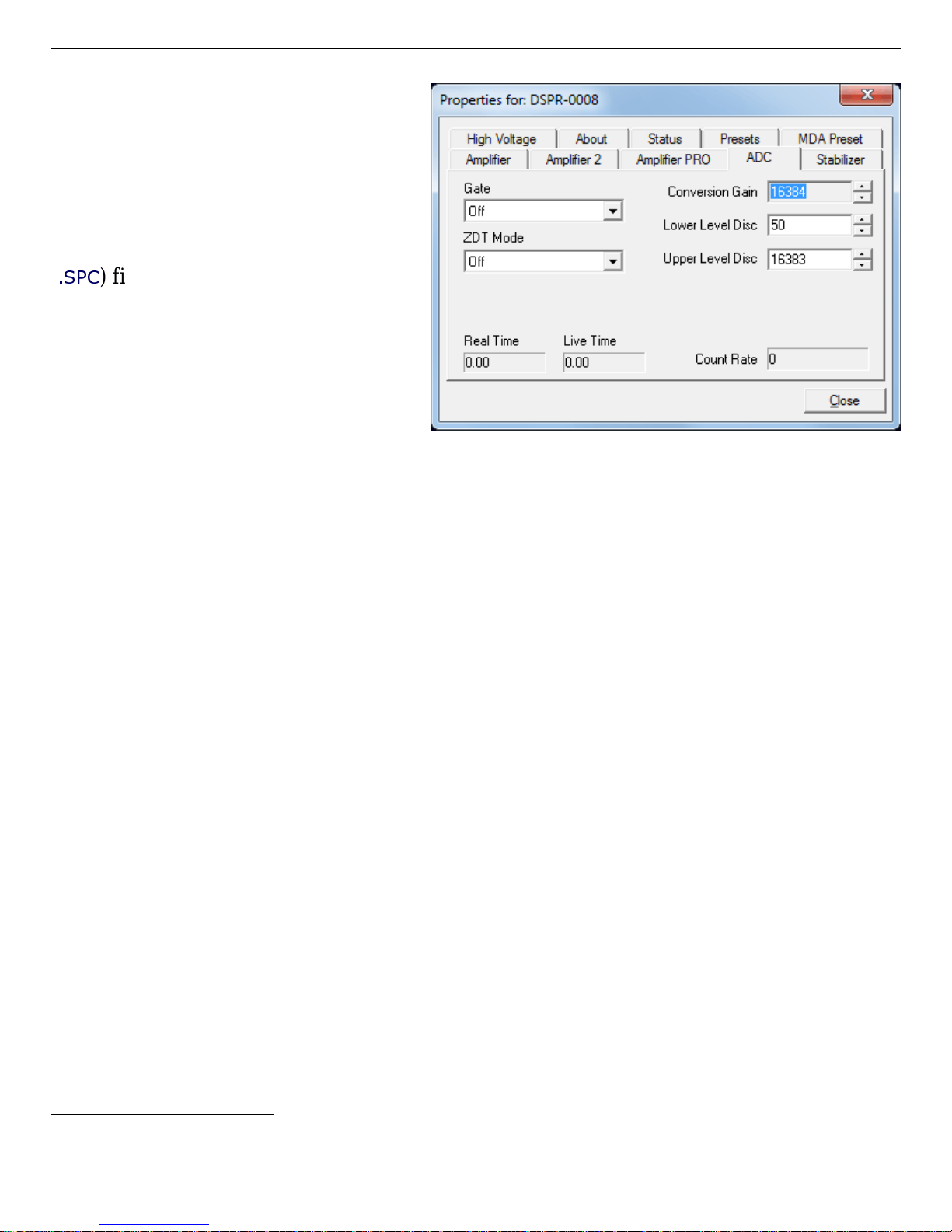
DSPEC Pro® Digital Gamma-Ray Spectrometer User’s Manual 794380D / 0914
ZDT Mode — See Section 1.6 for a
detailed discussion of this feature.
Use this droplist to choose the Off
(LTC spectrum only) or CORR_ERR
11
(ERR and ZDT spectra) mode.
If a
ZDT mode is selected, both spectra
are stored in the same spectrum
.SPC
(
) file. If you do not need the
ZDT spectrum, you should select
Off.
In MAESTRO, the display can
show either of the two spectra. Use
<F3> or Acquire/ ZDT Display
Figure 18. DSPEC Pro ADC Tab.
Select to toggle the display between
the two spectra. In the Compare mode, <F3> switches both spectra to the other type and
<Shift+F3> switches only the compare spectrum . This allows you to make all ty pes of
comparisons.
Conversion Gain — This sets the maximum channel number in the spectrum. If set to 16384,
the energy scale will be divided into 16384 channels. The conversion gain is entered in powers
of 2 (e.g., 8192, 4096, 2048). The up/down arrow buttons step through the valid settings for the
DSPEC Pro.
Upper- and Lower-Level Discriminators — The Lower Level Discriminator sets the level of
the lowest amplitude pulse that will be stored. This level establishes a low e r-level cutoff by
channel number for ADC conversions. T he Upper Level Disc riminator sets the level of the
highest amplitude pulse that will be stored. This level establishes an upper-level cutoff by channel number for storage.
2.3.5. Stabilizer
The Stabilizer tab (Fig. 19) lets you adjust and monitor the gain and zero stabilizers (which are
discussed in detail in the MAESTRO user manual). The value in each Adjustment section
shows how much adjustment is currently applied. The Initialize buttons set the adjustment to 0.
If the value approaches 90% or above the amplifier gain should be adjusted so the stabilizer can
continue to function — when the adjustment value reaches 100%, the stabilizer cannot make
further corrections in that direction. The Center Channel and Width fields show the peak
currently used for stabilization.
11
The NORM_CORR (LTC and ZDT) mode is typically not used; see Section 1.6.2.
34
Page 45
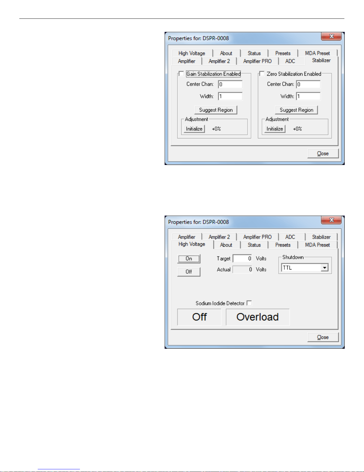
794380D / 0914 2. GETTING STARTED
To enable the stabilizer, enter the
Center Channel and Width values
manually or click the Suggest
Region button. Suggest Region
reads the position of the marker and
inserts values into the fields. If the
marker is in an ROI, the limits of the
ROI are used. If the marker is not in
an ROI, the center channel is the
marker channel and the width is 3×
the FWHM at this energy. Now
click the Enabled checkbox to turn
the stabilizer on. Until changed in
this dialog, the stabilizer will stay
Figure 19. DSPEC Pro Stabilizer Tab.
enabled even if the power is turned
off. When the stabilizer is enabled, the Center Channel and Width cannot be changed.
2.3.6. High Voltage
Figure 20 shows the High Voltage
tab, which allows you to turn the high
voltage on or off; set and monitor the
voltage; and choose the Shutdown
mode.
The shutdown can be TTL, ORTEC,
or SMART. The ORTEC mode is
used for all ORTEC detectors except
SMART-1 detectors. Use the SMART
option for those detectors. Check with
the detector manufacturer for other
detectors. The TTL mode is used for
most non-ORTEC detectors.
Figure 20. DSPEC Pro High Voltage Tab.
The polarity is determined by the
DIM or SMART-1 module, which also supplies the bias voltage. The recommended HV for
SMART-1 is displayed on the dialog. For other detectors, see the detector manual or data sheet
for the recommended voltage.
Enter the detector high voltage in the Target field, click On, and monitor the voltage in the
Actual field. Click the Off button to turn off the high voltage. The HV will not turn on if the
detector is sending a remote shutdown or overload signal. The Overload indicator means there
35
Page 46
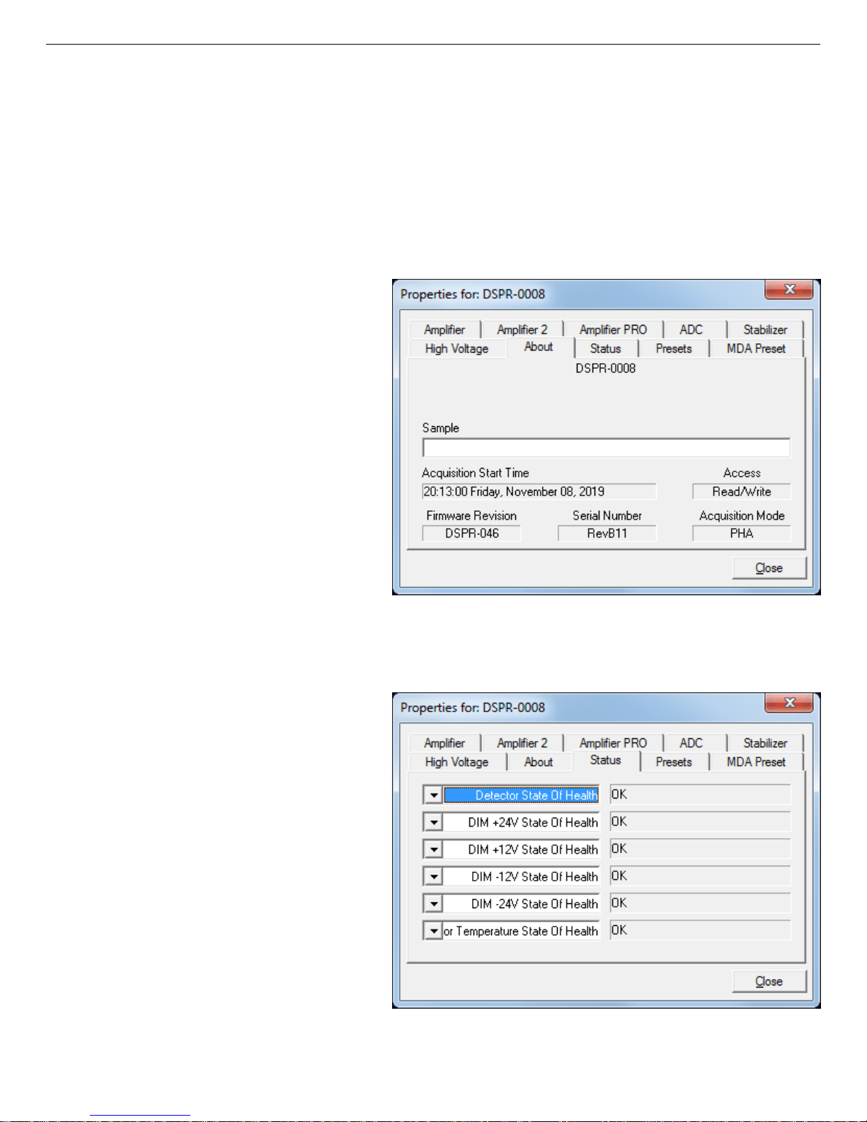
DSPEC Pro® Digital Gamma-Ray Spectrometer User’s Manual 794380D / 0914
is a bad connection in your system. The Shutdown indicator means that either the detector is
warm or you have chosen the wrong Shutdown or Source mode.
To use a Sodium Iodide Detector, mark the checkbox. This changes the gain and zero stabilizers to operate in a faster mode. For the DIM-296, the HV is controlled by the adjustment in the
Model 296 and not here.
2.3.7. About
This tab (Fig. 21) displays hardware
and firmware inform ation about the
currently selected DSPEC Pro as well
as the data Acquisition Start Time
and Sample description. In addition,
the Access field shows whether the
MCB is currently locked with a
password (see the password discussion in the MAESTRO user manual).
Read/Write indicates that the MCB
is unlocked; Read Only means it is
locked.
2.3.8. Status
Figure 22 shows the Status tab. There
are 21 values monitored at all times.
You can select any six of these to be
displayed simultaneously on the Status
tab. The parameters you choose can be
changed at any time so you can view
them as needed. Two types of values
are presented: OK or ERR, and
numeric value. The state-of-health
(SOH) parameters read OK or ERR.
If the state is OK, the parameter
stayed within the set limits during
the spectrum acquisition. If the parameter varied from the nominal value
by more than the allowed limit, the
Figure 21. DSPEC Pro About Tab.
Figure 22. DSPEC Pro Status Tab.
36
Page 47

794380D / 0914 2. GETTING STARTED
ERR is set until cleared by the program. T he numeric values are displayed in the units reported
by the DSPEC Pro. Security, Detector temperature, and Live detector temperature are
available only for SMART-1 detectors. For non-SMART-1 detectors, they show N/A.
The parameters displayed are:
Detector State of Health
This is OK if all the SOH are OK and ERR if any one is ERR.
DIM +24V State of Health
This is OK if the +24 volt supply in the DIM has stayed within 200 mV of +24 volts since
the last time the SOH was cleared.
DIM +12V State of Health
This is OK if the +12 volt supply in the DIM has stayed within 200 mV of +12 volts since
the last time the SOH was cleared.
DIM -12V State of Health
This is OK if the !12 volt supply in the DIM has stayed within 200 mV of !12 volts since
the last time the SOH was cleared.
DIM -24V State of Health
This is OK if the !24 volt supply in the DIM has stayed within 200 mV of !24 volts since
the last time the SOH was cleared.
Temperature State of Health
This is OK if the detector temperature has stayed below the high temperature limit set in the
detector since the last time the SOH was cleared. This is available only for SMART-1
detectors.
High Voltage State of Health
This is OK if the HV supply in the DIM has stayed within 200 V of specified bias voltage
since the last time the SOH was cleared.
Shutdown State of Health
This is OK if the detector shutdown has not activated since the last time the SOH was
cleared.
Preamplifier overload State of Health
This is OK if the preamplifier overload has not activated since the last time the SOH was
cleared.
37
Page 48

DSPEC Pro® Digital Gamma-Ray Spectrometer User’s Manual 794380D / 0914
Security State of Health
This is OK if the security test was passed at the end of the last spectrum acquisition. This is
available only for SMART-1 detectors.
Power State of Health
This is OK if the power to the DIM was constant during the last spectrum acquisition.
+24 volts
This is the current value of the +24 volt supply in the DIM as delivered to the detector.
+12 volts
This is the current value of the +12 volt supply in the DIM as delivered to the detector.
!12 volts
This is the current value of the -12 volt supply in the DIM as delivered to the detector.
!24 volts
This is the current value of the -24 volt supply in the DIM as delivered to the detector.
High Voltage
This is the current value of the high voltage bias supply in the DIM as delivered to the
detector.
Detector temperature
This is the detector temperature at the time the current spectrum acquisition stopped. This is
available only for SMART-1 detectors.
Live detector temperature
This is the detector temperature at the current time. This is available only for SMAR T-1
detectors.
Battery voltage
Not used in the DSPEC Pro.
Battery % full
Not used in the DSPEC Pro.
Battery time remaining
Not used in the DSPEC Pro.
38
Page 49
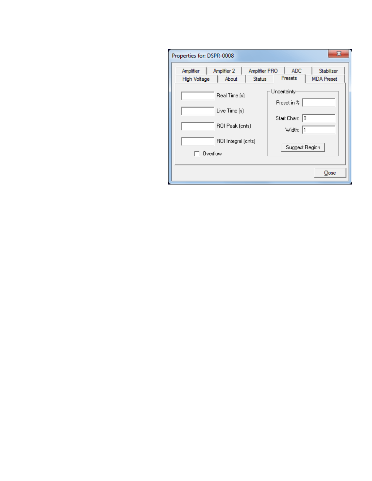
794380D / 0914 2. GETTING STARTED
2.3.9. Presets
Figure 23 shows the Presets tab.
MDA presets are on a separate tab.
The presets can only be set on an
MCB that is not acquiring data
(during acquisition the preset field
backgrounds are gray indicating
that they are inactive). You can use
any or all of the presets at one time.
To disable a preset, enter a value of
zero. If you disable all of the presets,
data acquisition will continue until
manually stopped.
The values of all presets for the
Figure 23. DSPEC Pro Presets Tab.
currently selected MCB are shown
on the Status Sidebar. These values do not change as new values are entered on the Presets tab;
the changes take place only when you start the next acquisition or Close the Properties dialog.
When more than one preset is enabled (set to a non-zero value), the first condition met during
the acquisition causes the MCB to stop. This can be useful when you are analyzing samples of
widely varying activity and do not know the general activity before counting. For example, the
Live Time preset can be set so that sufficient counts can be obtained for proper calculation of
the activity in the sample with the least activity. But if the sample contains a large amount of this
or another nuclide, the dead time could be high, resulting in a long counting time for the sample.
If you set the ROI Peak preset in addition to the Live Time preset, the low-level samples will
be counted to the desired fixed live time while the very active samples will be counted for the
ROI peak count. In this circumstance, the ROI Peak preset can be viewed as a “safety valve.”
Enter the Real Time and Live Time presets in units of seconds and fractions of a second. These
values are stored internally with a resolution of 20 milliseconds (ms) since the MCB clock
increments by 20 ms. Real time means elapsed time or clock time. Live time refers to the amount
of time that the MCB is available to accept another pulse (i.e., is not busy), and is equal to the
real time minus the dead time (the time the MCB is not available).
Enter the ROI Peak count preset value in counts. With this preset condition, the MCB stops
counting when any ROI channel reaches this value unless there are no ROIs marked in the MCB,
in which case that MCB continues counting until the count is manually stopped.
39
Page 50

DSPEC Pro® Digital Gamma-Ray Spectrometer User’s Manual 794380D / 0914
Enter the ROI Integral preset value in counts. With this preset condition, the MCB stops counting when the sum of all counts in all channels for this MCB marked with an ROI reaches this
value. This has no function if no ROIs are marked in the MCB.
The Uncertainty preset stops acquisition when the statistical or counting uncertainty of a userselected net peak reaches the value you have entered. Enter the Preset in % value as percent
uncertainty at 1 sigma of the net peak area. T he range is from 99% to 0.1% in 0.1% steps. You
have complete control over the selected peak region. The region must be at least 7 channels wide
with 3 channels of background on each side of the peak. Note that MAESTRO calculates this
preset once per 40 seconds. Therefore, the software will continue data acquisition up to
40 seconds after the preset has been reached, and the uncertainty achieved for a high count-rate
sample may be lower than the preset value.
Use the Start Channel and Width fields to enter the channel limits directly, or click Suggest
Region. If the marker is positioned in an ROI around the peak of interest, Suggest Region reads
the limits of the ROI with the marker and display those limits in the Start Chan and Width
fields. The ROI can be cleared after the preset is entered without affecting the uncertainty calculation. If the marker is not positioned in an ROI, the start channel is 1.5 times the FWHM below
the marker channel and the width is 3 times the FWHM.
The net peak area and statistical uncertainty are calculated in the same manner as for the
MAESTRO Peak Info command.
31
Marking the Overflow checkbox terminates acquisition when data in any channel exceeds 2
9
(>2×10
) counts.
!1
2.3.10. MDA Preset
The MDA preset (Fig. 24) can monitor up to 20 nuc lides at one time, and stops data collection
when the values of the minimum detectable activity (MDA) for all of the user-specified MDA
nuclides reach the needed value. Presets are expressed in Bq, and are evaluated every
40 seconds. The detector must be calibrated for energy in all spectroscopy applications, and for
efficiency in all applications but MAESTRO.
The MDA presets are implemented in the MCB (i.e., the entries you make on this screen are
saved in the MCB memory), and have no direct link to MDA methods selected in the analysis
options for applications such as GammaVision, ScintiVision™, ISOTOPIC, etc. The MDA
preset calculation uses the following formula:
40
Page 51
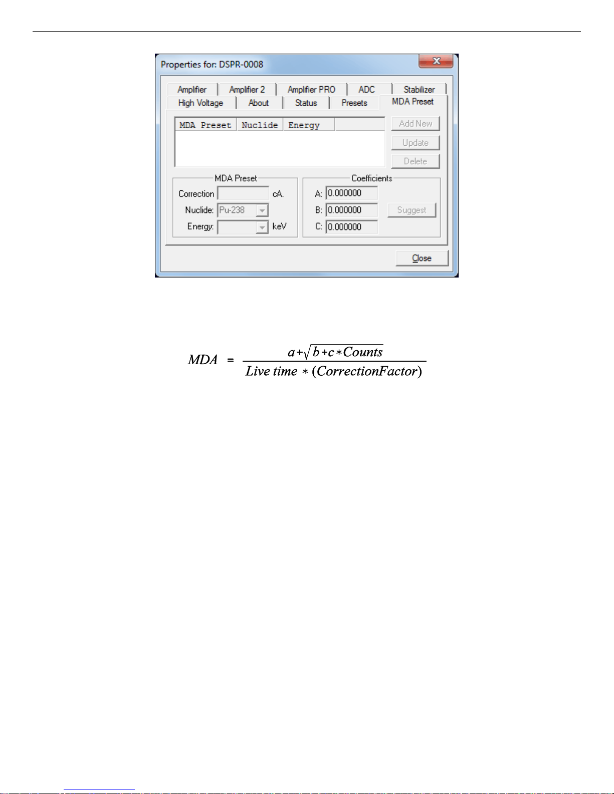
794380D / 0914 2. GETTING STARTED
Figure 24. DSPEC Pro MDA Preset Tab.
where:
a, b, and c are determined by the MDA criteria you choose.
Counts is the gross counts in an ROI that is 2.5×FWHM around the target peak energy.
Live time is evaluated in 40 second intervals for the MDA presets.
CorrectionFactor is the product of the calibration efficiency at the specified peak energy and
the peak’s branching ratio (yield) as listed in the working (active) library.
NOTE MAESTRO does not support efficiency calibration. The efficiency component in
the CorrectionFactor is set to 1.0; the preset field is labeled Correction instead of
MDA; and the preset is based on counting activity (cA) instead of becquerels. You
can enter the MDA preset either in counts; or corrected for factors such as sample
volume, attenuation, or calculated efficiency. For example, if you manually calculate the efficiency for a peak, you can enter a corrected MDA target value by multiplying the desired MDA value tim es the calculated efficiency, and entering the
product as the Correction.
41
Page 52
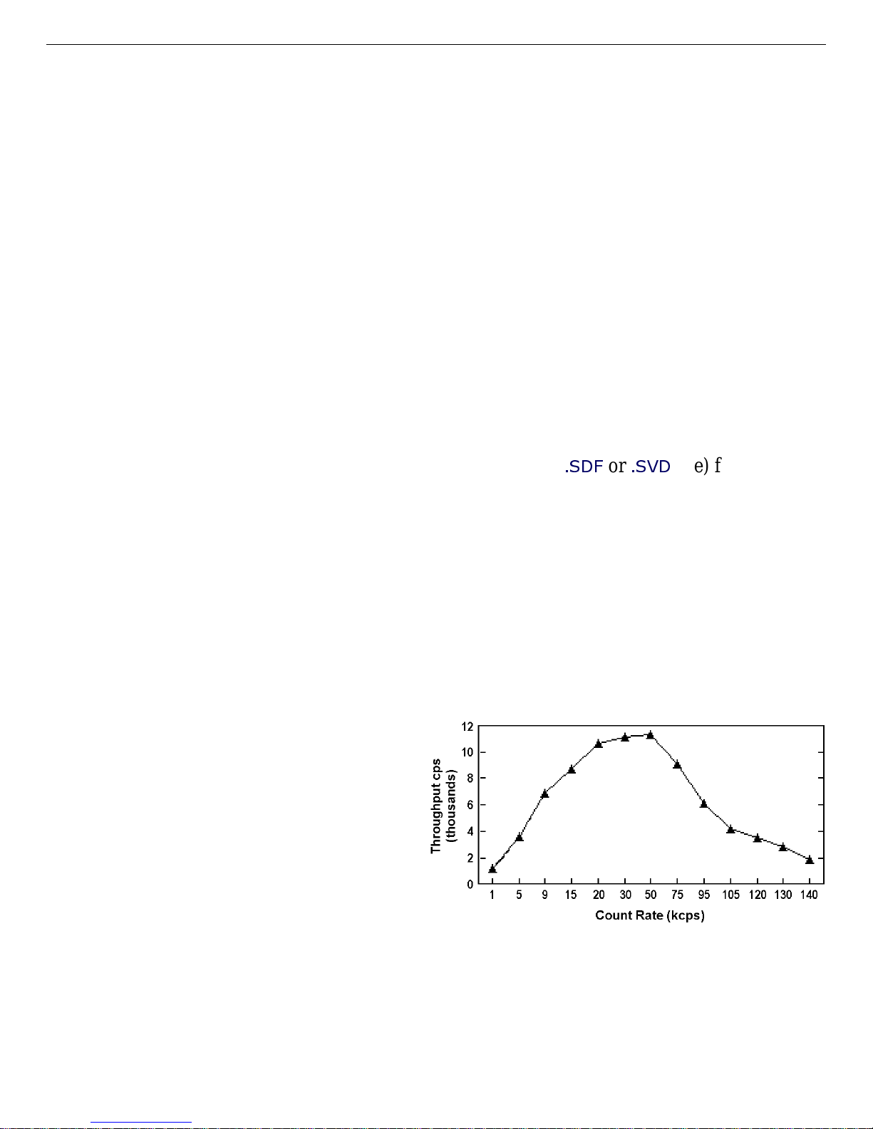
DSPEC Pro® Digital Gamma-Ray Spectrometer User’s Manual 794380D / 0914
To add an MDA preset, enter the preset value in the MDA or Correction field; select the
Nuclide and Energy; enter the desired values for coefficients a, b, and c; then click Add New.
To edit an existing preset, click to highlight it in the table. This will load its Nuclide, Energy,
and coefficients in the lower sections of the dialog. Change as needed, then click Update.
To remove a preset, click to highlight it in the table, then click Delete.
IMPORTANT These MDA presets are not dynamically calculated. Each time you add an
MDA preset to this table, its CorrectionFactor value is calculated and stored in
the MCB’s mem ory. If you then load a different library, change the efficiency
calibration, or change the system geometry, the spectroscopy application will
not update the existing CorrectionFactors, and your MDA presets may no
longer be applicable.
When using spectrum analy sis applications such as GammaVision and Scinti-
.SDF
or
.SVD
Vision, you can create an analysis options file (
file) for each
system geometry that you use; and include in it a set of MDA presets specific to
that geometry, efficiency calibration, and nuclide library. You can then recall
this tailored analysis options file as needed.
2.4. Setting the Rise Time in Digital MCBs
To achieve the best results when using a digital spectrometer, such as the DSPEC Pro, we
recommend that you set the rise time of the pulses being processed by the digital filter to the
minimum value for the resolution needed.
The pulse rise time (and also fall time) is
based on the time required for each pulse
to reach its peak value. This “peaking time”
is about twice that indicated by the conventional time constants displayed on the front
panel of commercial analog amplifiers. For
example, germanium detectors are often
specified at a 6-µs time constant; this setting is equivalent to 12-µs peaking (rise)
time in our digital spectrometers.
Up to some value of rise tim e, one
can expect improved resolution with increasing rise time ; there will, however, be a tradeoff in
maximum throughput to memory. Figure 25 illustrates an example of this tradeoff. ORTEC
Figure 25. An Example of the Tradeoff Between
Throughput and Count Rate.
42
Page 53
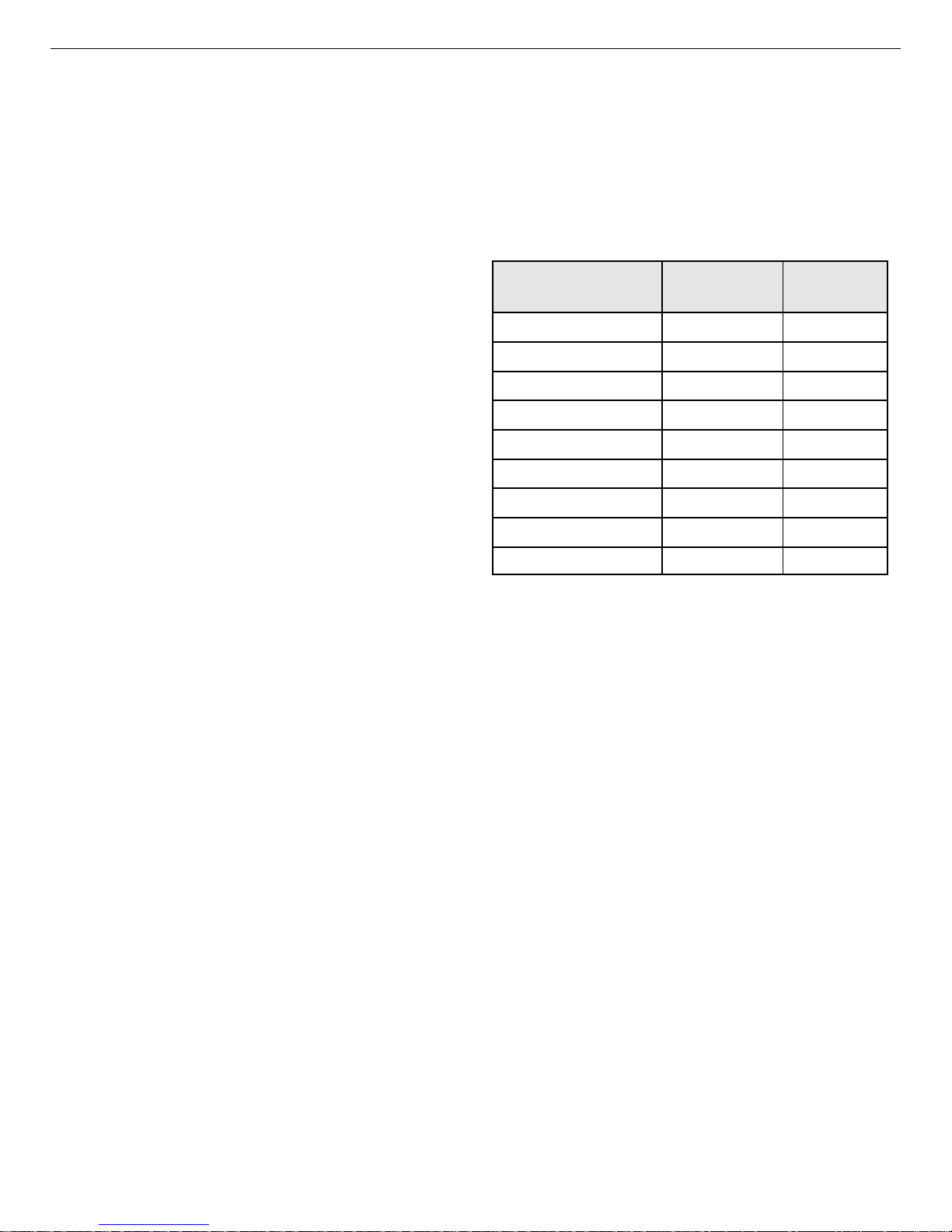
794380D / 0914 2. GETTING STARTED
digital spectrometers operate well above the peak of the throughput curve. Operating there
allows these instruments to handle an even higher rate of incoming counts, but with less data
into memory and, therefore, a longer count time to the sam e detection limit. It is possible to
move the peak of the curve to the right (more counts to m e mory with higher input count rate)
by reducing the pulse rise (and fall) time, thereby trading off resolution for maximum count rate.
Table 2 is a guide to choosing a count
rate that will ensure that the most efficient
operation of your digital spectrometer over
the range of anticipated input count rates
for your application — that is, at or below
the throughput peak — while achieving the
best resolution obtainable from the detector
Table 2. Rise Time Selection Guide.
Input Count Rate
Dynamic Range
0--->20000 9000 12
0--->50000 12500 8
0--->75000 23500 4
0--->100000 37000 2.4
Maximum
Throughput
Rise Time
(µs)
consistent with that requirement. Enter the
rise time that best matches your dynamic
range of count rate (note that the available
rise-time settings will vary by instrument;
this chart is a general guide only).
0--->150000 50000 1.6
0--->200k 70000 0.8
0--->220k 85000 0.6
0--->250k 100000 0.4
0--->300k 120000 0.2
The longest rise time shown in the table is
12 µs, even though some digital instruments
can be set for rise times as long as 23 µs. If throughput is not an issue because all samples are
low rate, increasing the rise time bey ond 12 µs might achieve a small improvement in resolution.
For planar detectors, such as ORTEC’s GLP, Si(Li), IGLET, and IGLET-X Series, operating at
longer rise times frequently gives improved resolution.
2.5. Troubleshooting
2.5.1. MAESTRO Does Not Connect with the DSPEC Pro
If properly installed and functioning MAESTRO software (or other C
cannot find and communicate with the DSPEC Pro, check for the following:
! T he DSPEC Pro is not turned on.
! T he USB cable is not properly connected.
! Check the Master Instrument List on the computer to ensure that the DSPEC Pro is on the
list. If it is not listed, shutdown and restart the DSPEC Pro, then re-run the MCB
Configuration program according to Section 2.2.4.
ONNECTIONS programs)
43
Page 54

DSPEC Pro® Digital Gamma-Ray Spectrometer User’s Manual 794380D / 0914
! See the CONNECTIONS Driver Update Kit instructions for more detailed information on
using MCB Configuration.
44
Page 55

3. SPECIFICATIONS
3.1. DSPEC Pro
Display 240 × 160 pixel, backlit LCD provides status information, instrument ID, bias information, live and real tim e.
Maximum System Throughput >100,000 cps; depends on shaping parameters.
Enhanced Throughput Mode Protection time from 0.1 µs to 200 µs in 25 ns increments.
LFR Mode Highest Throughput
(minimum Protection Time)
Off (Rise Time + flattop) (2 × Rise Time + Flattop)
On (3 × Rise Time + 2 × Flattop) (6 × Rise Time + 3 × Flattop)
Lowest Throughput
(maximum Protection Time)
System Gain Settings
! Coarse Gain Settings 1 to 32 in binary steps (1, 2, 4, 8, 16, 32).
! Fine Gain 0.45 to 1.
The available range of gain settings supports all types of HPGe detectors. Specifically the following maximum energy values are achievable using the standard ORTEC preamplifier (maximum to minimum gain):
12
! COAX 187 keV–12 MeV
! GLP/SLP 16.5 keV–1 MeV
Amplifier Input Polarity Selectable via software.
System Conversion Gain Software selectable as 16384, 8192, 4096, 2048, 1024, or 512
channels.
Preamplifier Software selectable as either resistive or TRP preamplifier.
ADC Gate (Not available for -PLUS [transistor-reset preamplifier] or SMART-1 detectors.)
Accepts a positive TTL input via the DIM’s “Inhibit” BNC. Signal must occur prior to and
extend 0.5 µs beyond peak detect. Software-selectable as off, coincidence, or anticoincidence.
12
For the legacy LO-AX and IGLET-X detector types, the respective energy ranges are 94 keV–6 MeV and
8 keV–500 keV.
45
Page 56

DSPEC Pro® Digital Gamma-Ray Spectrometer User’s Manual 794380D / 0914
Digital Filter Shaping-Time Constants
! Rise time 0.8 µs to 23 µs in steps of 0.2 µs.
! Flattop 0.3 to 2.4 in steps of 0.1 µs.
Dead-Time Correction Extended live-time correction according to Gedcke-Hale method.
Accuracy: area of reference peak changes <±3% from 0 to 50,000 cps.
Low-Frequency Rejector (LFR) When ON, removes low-frequency (<3 kHz) input noise
from spectrum.
Linearity
! Integral Nonlinearity <±0.025% over top 99.5% of spectrum, measured with a mixed
source (
55
Fe at 5.9 keV to 88Y at 1836 keV).
! Differential Nonlinearity <±1% (measured with a BNC pulser and ramp generator).
System Temperature Coefficient
! Gain <50 ppm/EC (typically <30 ppm/EC).
! Offset <3 ppm/EC, with rise and fall times of 12 µs and flattop of 1 µs (similar to analog
6-µs shaping).
Pulse Pileup Rejector Autom a tically set threshold. Pulse-pair resolution typically 500 ns.
3
Automatic Digital Pole-Zero Adjustment
Can be set automatically or manually. Remote
diagnostics via Insight Virtual Oscilloscope mode in MAESTRO.
Digital Gated Baseline Restorer Software-controlled adjustment of the restorer rate (Fast,
4
Slow, and Auto
).
ADC Gate (Not available for -PLUS [transistor-reset preamplifier] or SMART-1 detectors.)
Accepts a positive TTL input via the DIM’s “Inhibit” BNC. Signal must occur prior to and
extend 0.5 µs beyond peak detect. Software-selectable as off, coincidence, and anticoincidence.
LLD Digital lower-level discriminator set in channels. H a rd cutoff of data in channels below
the LLD setting.
ULD Digital upper-level discriminator set in channels. Hard cutoff of data in channels above
the ULD setting.
Ratemeter Monitor the input count rate on the DSPEC Pro display or computer screen.
46
Page 57

794380D / 0914 3. SPECIFICATIONS
Battery Internal battery-backed up mem ory to maintain settings in the event of a power
interruption.
Presets Multiple presets can be set on any or all of the following:
! Real Time Stops data collection when the real time reaches this value.
! Live Time Stops data collection when the live time reaches this value.
! ROI Integral Integral count stops data collection when the sum of counts in all ROI
channels reaches this value.
! ROI Peak Peak count stops data acquisition when the count in any ROI channel reaches
this value (maximum value of 2
31
!1 counts [2×10⁹]).
! Uncertainty Sets the required statistical accuracy on a key peak (for example: stop
60
counting when the activity of
Co is known to be better than 5%).
! Multi-Nuclide MDA Stops data collection when the value of the minimum detectable
activity (MDA) for up to 20 user-specified MDA nuclides reaches the needed value.
The presets are implemented in hardware so the computer does not have to poll the
DSPEC Pro for the preset to operate. See Section 2.3.10 for details on the MDA preset
calculation.
31
! Data Overflow Terminates acquisition when data in any channel exceeds 2
!1 (2×10⁹)
counts.
Digital Spectrum Stabilizer
! Stabilization Peak centroid (zero and gain) channel 2 to 16384; stabilization window
width (zero and gain) ±1 to ±256 channels.
! Zero Correction Resolution ±64 channels with a minimum adj ustment of 0.1 channel
out of 16384 total channels.
! Gain Correction Resolution 0.00025% (from 99.5% to 100.5% in 4096 steps).
3.1.1. Electrical and Mechanical
Dimensions
! DSPEC Pro 8.1 cm H × 20.3 cm W × 24.9 cm D (3.2 in. × 8 in. × 9.8 in.) .
! DIM 11.2 cm H × 3.13 cm W × 6.5 cm D (4.4 in. × 1.25 in. × 2.6 in.).
47
Page 58

DSPEC Pro® Digital Gamma-Ray Spectrometer User’s Manual 794380D / 0914
Weight
! DSPEC Pro 1.0 kg (2.2 lb).
! DIM: <240 gm (0.5 lb).
Operating Temperature Range 0 to +50EC, including LCD display.
3.1.2. Connectors
DETECTOR Multi-pin connector (13W3) carries the following:
! Preamp Power 1 W only (+12V, !12V, +24V, !24V, 2 GND)
! Amp In Normal amplifier input
! Inhibit For TRP or gate
! Battery Power (5–12 V) for DIM
! Control for HV
! SMART-1 HPGe detector control
USB High-speed USB for communication with computer.
12-15V DC External power input from wall-mounted dc power supply, +12 V dc, <1.25 A,
center contact positive. The connector is RAPC712 (Switchcraft), 5.5 mm × 2.5 mm.
SAMPLE CHANGE OUT Rear-panel BNC connector, TTL compatible.
SAMPLE READY IN Rear-panel BNC connector accepts TTL level signal from sample
changer. Software-selectable polarity.
3.2. HPGe High-Voltage Detector Interface Modules
The DSPEC Pro offers high-voltage supply flexibility in the form of modules that connect the
detector to the MCA and provide bias and SMART-1 support (if appropriate). These modules
have an input connector that connects to the DETECTOR connector (discussed in Section 3.1.2).
On a SMART-1 detector, the high voltage m odule will be hardwired to the detector. To support
older detectors, a detector interface module (DIM) with 12-inch leads connect the detector and
DSPEC Pro, providing HV bias and control. The leads are as follows:
! 9-pin D preamplifier power cable
! Analog In
! Shutdown In
! Bias Out
! Inhibit In
48
Page 59

794380D / 0914 3. SPECIFICATIONS
The DSPEC Pro uses the following DIMs:
! DIM-POSGE For any non-SMART-1, positive-bias, HPGe detector (includes leads
with mating connectors for existing detector cabling), +500 V to
+5000 V.
! DIM-NEGGE For any non-SMART-1, negative-bias HPGe detector (includes leads
with mating connectors for existing detector cabling), !500 V to
!5000 V.
! DIM-POSNAI For any positive-bias NaI detector (includes leads with mating
connectors for existing detector cabling), +100 V to +1800V, 300 µA.
! DIM-296 For any positive-bias NaI detector (includes Model 296 ScintiPack
tube base/preamplifier/bias supply for NaI detectors w ith 14-pin, 10
stage photo multiplier tubes), 0 V to +1200 kV.
In all cases except the DIM-296, the bias voltage setting and shutdown polarity are set via
MAESTRO or other C
ONNECTIONS software.
The SMART-1 detector provides detector state-of-health information as discussed above and in
Section 1.7.
3.3. Feature Mask Bits
The following table describes the feature bits from the SHOW_FEATURES command discussed
on page 74. If the feature is supported in the DSPEC Pro the bit is set to 1; if the feature is not
supported, the bit is 0.
Bit Meaning
0 Software-selectable conversion gain
1 Software-selectable coarse gain
2 Software-selectable fine gain
3 Gain stabilizer
4 Zero stabilizer
5 PHA mode functions available
6 MCS mode functions available
7 List mode functions available
8 Sample mode functions available
9 Digital Offset (e.g., 920)
49
Page 60

DSPEC Pro® Digital Gamma-Ray Spectrometer User’s Manual 794380D / 0914
Bit Meaning
10 Software-selectable analog offset
11 HV power supply
12 Enhanced HV (SET_HV, SET/SHOW_HV_POL, SHOW_HV_ACT)
13 Software-selectable HV range (ENA_NAI, DIS_NAI)
14 Auto PZ (START_PZ_AUTO)
15 Software-selectable manual PZ (SET/SHOW_PZ)
16 Battery-backed, real-time clock (SHOW_DATE/TIME, SHOW_DATE/TIME_START)
17 Sample changer support (SET/SHOW_OUTPUT, SHOW_INPUT)
18 One-button acquisition (ENA/DIS/SHOW_TRIG_SPEC, MOVE)
19 Nomadic (likely to move between opens)
20 Local app data (SET_DATA_APP, SHOW_DATA_APP)
21 Software-retrievable serial number
22 Power management commands
23 Battery status support (SHOW_STAT_BATT)
24 Software-selectable AMP polarity (SET/SHOW_GAIN_POLAR)
25 Support for flattop optimization (ENA/DIS_OPTI)
26 Stoppable AutoPZ (STOP_PZ_AUTO)
27 Network support (e.g., DSPEC)
28 Multi-drop serial support (e.g., MicroNOMAD®)
29 Software-selectable DPM address (SET_DPM_ADDR)
30 Multiple devices (e.g., 919)
31 Software-selectable ADC gate mode (SET_GATE...)
32 Software-downloadable firmware
33 Time histogramming functions available (e.g., 9308)
34 Software-selectable lower level discriminator
35 Software-selectable upper level discriminator
36 MCS-mode SCA input available
37 MCS-mode positive TTL input available
38 MCS-mode fast-negative NIM input available
39 MCS-mode discriminator input available
40 Software-switchable MCS-mode discriminator edge
41 Software-programmable MCS-mode discriminator level
42 Software-programmable SCA upper and lower thresholds
43 Software-selectable MCS-mode input sources
44 Uncertainty/statistical preset (SET_UNCERT_PRES)
45 Features vary by input (SHOW_FEATURES depends on device/segment;multi-input MCBs only)
50
Page 61

794380D / 0914 3. SPECIFICATIONS
Bit Meaning
46 Software-selectable HV shutdown mode (SET/SHOW/VERI_SHUT)
47 Software-selectable shaping time constants (SET_SHAP)
48 Explorable shaping time constants (SHOW_CONFIG_SHAP)
49 Advanced shaping time (SET_SHAP_RISE, SET_SHAPE_FLAT, etc.)
50 Software-selectable BLR (ENA/DIS/SHO_BLR_AUTO SET/SHO/VERI_BLR)
51 SHOW_STATUS command supported (returns $M record)
52 Overflow preset (ENA/DIS/SHO_OVER_PRES)
53 Software-enabled, MicroNOMAD-style audio clicker (ENA/DIS_CLICK)
54 Software-readable thermistor (SHOW_THERM)
55 Floating-point fine gain (SET/SHO/VERI/LIST_GAIN_FINE)
56 Software-enabled pileup rejector. (ENA/DIS/SHO_PUR, SET/VERI_WIDT_REJ)
57 Alpha-style HV power (SHOW_HV_CURRENT)
58 Software-readable vacuum (SHOW_VACUUM)
59 Acquisition alarms (ENA/DIS/SHO_ALARM)
60 Hardware acquisition trigger (ENA/DIS/SHO_TRIG)
61 Ordinal numbers for shaping times (SET_SHAP 0, SET_SHAP 1, ...)
62 Query gain ranges (LIST/VERI_GAIN_FINE, ..._COAR, ..._CONV)
63 Routable inputs (SET/SHOW_INPUT_ROUTE)
64 External dwell support (ENA/DIS_DWELL_EXT)
65 Selectable SUM or REPLACE MCS modes (ENA/DIS_SUM)
66 External start of pass support (ENA/DIS/SHO_START_EXT)
67 Explorable with MCS list commands (LIST_SOURCE, LIST_LLSCA, LIST_ULSCA)
68 Device supports the MDA preset
69 Software-selectable ADC type (Matchmaker™)
70 Has ability to daisy-chain MCBs (DART)
71 ZDT functions available (DSPEC Plus, DSPEC jr, DSPEC jr 2.0, DSPEC Pro)
72 DSPEC Plus-style Insight triggering (LIST/SET_TRIG_SAMP)
73 Multiple inputs per connection (for example, OCTÊTE® Plus)
74 Hardware count-rate meter (SH_CRM)
75 Has multiple ZDT modes (SET/SHOW/LIST_MODE_ZDT)
76 Has multi-nuclide MDA preset
77 Has MCS Replace then Sum Mode (SET_RPLSUM)
78 Has programmable external dwell voltage capability
79 No Peak Preset feature (M3CA and OASIS)
80 Programmable pulser (OASIS)
81 Programmable Vacuum/HV interlock (OASIS)
51
Page 62

DSPEC Pro® Digital Gamma-Ray Spectrometer User’s Manual 794380D / 0914
Bit Meaning
82 Programmable Current/HV interlock (OASIS) 0
83 Explorable Stabilizer (LIST_GAIN_ADJU, LIST_ZERO_ADJU)
84 Has programmable input impedance (MCS)
85 Advanced shaping-time feature has no CUSP (digiDART, DSPEC jr 2.0, DSPEC Pro)
86 Selectable HV rise-time (SET/SHOW/LIST_HV_RISE) (SBS-60)
87 —
88 Monitor command support (SHOW_MONI_MAX/LABEL/VALUE)
89 SMART-1 Detector support (SHOW_SMART_DET, SHOW_SNUM_DET, SHOW_HV_RECO)
90 Nuclide report (SET/SHOW_NUCL_COEF, SET/SHOW_ROI_NUCL, ...)
91 Interactive Display Features Such as Nuclide Report
92 Advanced Stored Spectra (SH_SPEC_COUNT, SET/SHOW_SPEC_ID, MOVE)
93 SET/SHOW_VIEW in MCBs with Dual-Port Memory or printer port interfaces, LIST_VIEW in all
MCBs
94 Connected to MCB via RS-232 (slow) port
95 No SET_HV_POSI, SET_HV_NEGA, ENA_NAI and DIS_NAI
96 Low Frequency Rejector (ENA/DIS/SHOW_LFR)
97 Resolution Enhancer (ENA/DIS/SH_RENHANCER, SET/SHOW_RETABLE idx,val)
98 SET_MODE_RELIST for Resolution Enhancer List Mode
99 Readable Sample mode time per channel (SH_TIME_SAMPLE)
100 Adjustable Sample mode time per channel (SET/LIST_TIME_SAMPLE)
101 List Mode data streamed and formatted as in digiBASE
102 Supports ETP mode (ENA/DIS/SHOW_ETP)
103 List Mode data streamed and formatted as in DSPEC PRO
104 SET/SHOW/LIST_PZ using floating point microseconds
105 —
106 —
107 —
52
Page 63
4. FIRMWARE COMMANDS AND RESPONSES
Most software comm unication with the DSPEC Pro takes place through the CONNECTIONS software layer. C
development with our C
(A11). Use the DLL interface call
to send commands to instruments and receive responses.
The comma nds consist of a command header that may be followed by numeric parameter values.
The header consists of a verb; a verb and noun; or a verb, noun, and modifier; each separated by
underscores. The first four letters of a word in a command will always be enough to uniquely
identify that word when com posing commands for the instrument. For example, the command
ENABLE_GAIN_STABILIZATION can be abbreviated to ENAB_GAIN_STAB.
Numeric parame ters are unsigned integer numbers that follow the comma nd header separated by
one or more spaces. Specific commands require multiple parameters, separated by commas, that
specify numeric quantities related to the operation of the MCB, such as live time or conversion
gain. The command SET_WINDOW 0,8192 has two parameters, 0 and 8192, which set the
window of interest to start at channel 0 and continue for 8192 channels.
ONNECTIONS is used by all ORTEC software and can be accessed for other software
ONNECTIONS Programmer’s Toolkit with Microsoft ActiveX
MIOComm
or the ActiveX control UCONN’s
®
Comm
Controls
method
4.1. Command Format
Some parameters are optional and are delimited by square brackets in the command prototype
line to distinguish them from mandatory param eters (e.g. , SET_WINDOW [start,length]). Commands with optional parameters can be sent to the MCB without the optional parameters, in
which case the instrument behavior will be explained in the command description.
4.2. Error Codes
On each completion of the command, the MCB returns a macro error code and micro error code.
The macro error code represents the general class of error with 0 meaning no error, and the
micro error code represents the sub-class of error with 0 meaning no error. In case of error
condition, you can use the
MIOGetLastError
(ActiveX control interface).
Macro error codes:
0 Success
1 Power-up just occurred
2 Battery-backed data lost
(DLL interface) or
GetErrMajor, GetErrMinor
129 Command syntax error
53
Page 64

DSPEC Pro® Digital Gamma-Ray Spectrometer User’s Manual 794380D / 0914
131 Command execution error
132 Invalid Command
For macro code 129 (syntax error) or 131 (execution error), the following apply:
1 Invalid Verb
2 Invalid Noun
4 Invalid Modifier
128 Invalid first parameter
129 Invalid second parameter
130 Invalid third parameter
131 Invalid fourth parameter
132 Invalid number of parameters
133 Invalid command
134 Response buffer too small
135 Not applicable while active
136 Invalid command in this mode
137 Hardware error
138 Requested data not found
Micro error codes:
0 Success
1 Input already started/stopped
2 Preset already exceeded
4 Input not started/stopped
64 Parameter was rounded (for decimal numbers)
128 No sample data available
4.2.1. Dollar Response Records
SHOW and STEP commands respond with a single dollar response record followed immediately
by a percent response record. All valid dollar response records for each command are listed in
the command dictionary.
The following list provides the general form of each dollar response record for the MCB API. In
this list, lower case letters represent numeric values. The letters “ccc” always represent an 8-bit
54
Page 65

794380D / 0914 4. FIRMWARE COMMANDS AND RESPONSES
unsigned checksum of all characters on the record up to but not including the checksum characters, and <CR> represents the ASCII carriage return character.
$Axxxccc<CR> xxx is a single 8-bit unsigned number.
$Cxxxxxccc<CR> xxxxx is a single 16-bit unsigned number.
$Dxxxxxyyyyyccc<CR> xxxxx and yyyyy are 16-bit unsigned numbers.
$Exxxxxccc<CR> xxxxx is a single 16-bit alarm mask.
$Fssss...<CR> ssss... is a variable length ASCII character sequence (no
checksum is sent with this record).
$Gxxxxxxxxxxccc<CR> xxxxxxxxxx is a single 32-bit unsigned number.
$IT<CR> True response to a SHOW command (no checksum).
$IF<CR> False response to a SHOW com mand (no checksum).
$Jxxxxxyyyyy...ccc<CR> Response to SHOW_CONFIGURATION com mand.
$Mxxxxxxxxxx...ccc<CR> Response to SHOW_STATUS command.
$Nxxxyyyzzzccc<CR> xxx, yyy, and zzz are 8-bit unsigned numbers.
4.2.2. MCB Commands
This section lists each command with a description of its operation. The descriptions include a
list of any error codes that may result. As described in the two preceding sections, the usual
response is a macro error code of 0 and a micro error code of 0 (no errors). T hough syntax and
communication error responses may result from any comm a nd, in practice, these error responses
rarely occur on systems with reliable communication hardware running debugged software.
The commands are listed in alphabetical order, each starting with a command prototype line.
Uppercase letters, numeric digits, blank space, and special sym bols such as the underscore “_”
and comma 13 “,” in the prototype line are literal text to be sent to the MCB exactly as they
appear. Lowercase letters in the prototype line represent num eric values as described in the
accompanying text; they should not be sent literally to the MCB but should be replaced by an
appropriate numeric value. In this section the term <CR> represents the ASCII carriage return
character, decimal value 13; and the character “_” represents the ASCII underscore character,
decimal value 95.
CLEAR
The channels of spectral data in the window of interest (see SET_WINDOW command) are
set to zero. The live time and true time counters are also set to zero. This command is equivalent to the combination of CLEAR_COUNTER and CLEAR_DATA commands.
55
Page 66

DSPEC Pro® Digital Gamma-Ray Spectrometer User’s Manual 794380D / 0914
CLEAR_ALL
This comma nd is equivalent to the combination of CLEAR_COUNTER, CLEAR_DATA,
CLEAR_PRESETS, and CLEAR_ROI commands.
CLEAR_COUNTER
The live time and true time counters are set to zero.
CLEAR_DATA
The channels of spectral data in the window of interest (see SET_WINDOW command) are
set to zero. The ROI flags are not changed, nor are the presets changed.
CLEAR_HV_HEALTH
Clears (resets) the state-of-health bits. This comma nd clears the SOH bits in the DIM and
does not affect the stored SOH (which is reported when the instrument is not acquiring data).
CLEAR_LIST
Clears data and resets acquisition in List Mode. The response is the same as the CLEAR
command.
CLEAR_MDA_PRESET
Clears all MCA preset values. This command is used to quickly clear the list of MDA preset
values.
CLEAR_PRESETS
The live time, true time, ROI integral, ROI peak, and overflow presets are all set to zero
(disabled).
CLEAR_ROI
The region-of-interest flags for the channels in the window of interest (see SET_WINDOW
command) in the currently selected device (see SET_DEVICE command) are cleared.
CLOSE_FILE_FLASH crc
No function in the DSPEC Pro; included for backward com patibility.
COMP
No function in the DSPEC Pro; included for backward com patibility.
DISABLE_BLRE_AUTOMATIC
Disables the automatic determ ination of base line restorer time constant. See also ENABLE_
BLRE_AUTOMATIC, SET_BLRE, and SHOW_BLRE.
56
Page 67

794380D / 0914 4. FIRMWARE COMMANDS AND RESPONSES
DISABLE_ETP
Returns the DSPEC Pro to normal operation if in Enhanced Throughput (ETP) mode. See
also ENABLE_ETP, SHOW_ETP, SET_TIME_ETP, LIST_TIME_ETP, and
SHOW_TIME_ETP.
DISABLE_GAIN_STABILIZATION
Stops stabilization of the gain peak while data is being acquired. The gain stabilization
adjustment is held at its current value until either gain stabilization is reenabled with the
ENABLE_GAIN_STABILIZATION command or reinitialized with the IN ITIALIZE_
GAIN_STABILIZATION, SET_GAIN_PEAK or SET_GAIN_WIDTH command. See also
SHOW_GAIN_STABILIZATION.
DISABLE_GATE_ROUTE
No function in the DSPEC Pro; included for backward com patibility.
DISABLE_HV
Turns off the high-voltage enable signal of the DSPEC Pro. See the section on the bias
supply for more information about the high-voltage output. See also ENABLE _HV and
SHOW_HV.
DISABLE_HV_DIM
Disables the use of the MCB connector on the back of the DSPEC Pro and causes the
DSPEC Pro to suppress State of Health information (see SHOW_HV_HEA LTH command).
Also, the command disables polling of a standard DIM module (e.g. DI M-POSNAI,
DIM-POSGE, DIM-NEGGE, or DIM-296) by the DSPEC Pro.
DISABLE_LFR
Returns the DSPEC Pro to normal operation if the LFR filter is enabled. See also ENABLE_
LFR and SHOW_LFR.
DISABLE_NAI
Switches the stabilizers to Ge mode. See ENABLE_NAI.
DISABLE_OPTI_NEED
Disables the reporting of an error when the DSPEC Pro has not been optimized.
DISABLE_OVERFLOW_PRESET
Disables the overflow preset. Channels that receive a count when they contain 2147483647
counts, the maxim um number of counts, will roll over to zero counts if the overflow preset is
disabled. See also ENABLE_OVERFLOW_PRESET and SHOW_OVERFLOW_PRESET.
57
Page 68

DSPEC Pro® Digital Gamma-Ray Spectrometer User’s Manual 794380D / 0914
DISABLE_PZ_AUTOMATIC
Disables the automatic pole zero mode. See also ENABLE_PZ_AUTOMATIC.
DISABLE_PZ_NEED
Disables the reporting of an error when the DSPEC Pro has not been pole zeroed.
DISABLE_REMOTE
No function in the DSPEC Pro; included for backward com patibility.
DISABLE_RENH
Returns the DSPEC Pro to normal operation if the Resolution Enhancer is enabled. See
ENABLE_RENH.
DISABLE_THRESHOLD_AUTOMATIC
DISABLE_THRESHOLD_SAMPLE
DISABLE_TRIGGER_SPECIAL
No function in the DSPEC Pro; included for backward com patibility.
DISABLE_TRIGGER
Disables the data acquisition trigger that was enabled by the ENABLE_TRIGGER
command. Cancels an ENABLE_TRIGG ER_REP if it is issued before the acquisition starts.
See ENABLE_TRIGGER, TRIGGER, and SHOW_TRIGGER.
DISABLE_ZERO_STABILIZATION
Stops stabilization of the zero peak while data is being acquired. The zero stabilization
adjustment is held at its current value until either zero stabilization is reenabled with the
ENABLE_ZERO_STABILIZATION command or reinitialized with the INITIALIZE_
ZERO_STABILIZATION, SET_ZERO_CHANNEL or SET_ZERO_WIDTH commands.
See also SHOW_ZERO_STABILIZATION.
DISABLE_ZDT
Returns the DSPEC Pro to normal operation if in zero-dead-time (ZDT) mode. See
ENABLE_ZDT.
ENABLE_BLRE_AUTOMATIC
Enables the automatic determ ination of baseline restorer time constant. See also DISABLE_
BLRE_AUTO, SHOW_BLRE, and SET_BLRE.
ENABLE_ETP
Sets the DSPEC Pro to Enhanced Throughput (ETP) mode. See also DISABLE_ETP,
SHOW_ETP, SET_TIME_ETP, LIST_TIME_ETP, and SHOW_TIME_ETP.
58
Page 69

794380D / 0914 4. FIRMWARE COMMANDS AND RESPONSES
ENABLE_GAIN_STABILIZATION
Enables the stabilization of the gain peak. See also DISABLE_GAIN_STABILIZATION,
SHOW_GAIN_STABILIZATION, and INITIALIZE_GAIN_STABILIZATION.
ENABLE_HV
Turns on the high-voltage enable output of the DSPEC Pro. See also DISABLE_HV and
SHOW_HV.
ENABLE_HV_DIM
Enables the DSPEC Pro to work with a standard DIM (e.g. DIM-POSNAI, DIM-POSGE, or
DIM-NEGGE, DIM-296). This command causes the DSPEC Pro to poll the DIM and return
state-of-health information to a controlling program (see SHOW_HV_HEA LTH command).
ENABLE_LFR
Sets the DSPEC Pro to LFR mode. See also DISABLE_LFR and SHOW_LFR.
ENABLE_NAI
Switches the stabilizers to NaI mode. The stabilizers use the “fine” adjustme nt in NaI
mode and the “very fine” adjustment in Ge mode. See DISABLE_NAI.
ENABLE_OPTI_NEED
Enables the reporting of an error when the DSPEC Pro needs optimizing.
ENABLE_OVERFLOW_PRESET
Enables the overflow preset. Channels that receive a count when they contain 2147483647
counts, the maximum number of counts, will stop the acquisition if the overflow preset is
enabled. The channel that caused the preset to complete will contain 2147483647 counts.
See also DISABLE_OVERFLOW_PRESET and SHOW_OVERFLOW_PRESET
commands.
ENABLE_PZ_AUTOMATIC
Enables the automatic pole zero mode. See also DISABLE_PZ_AUTO and SHOW_PZ_
AUTO.
ENABLE_PZ_NEED
Enables the reporting of an error when the DSPEC Pro needs pole zeroing.
ENABLE_REMOTE
No function in the DSPEC Pro; included for backward com patibility.
59
Page 70

DSPEC Pro® Digital Gamma-Ray Spectrometer User’s Manual 794380D / 0914
ENABLE_RENH
Sets the DSPEC Pro to Resolution Enhancer mode. See also SHOW_RENH.
ENABLE_THRESHOLD_AUTOMATIC
Enables automatic determ ination of the positive and negative thresholds. See also
DISABLE_THRESHOLD_AUTO, SHOW_THRESHOLD_AUTO, SET_THRESHOLD_
NEGATIVE, and SET_THRESHOLD_POSITIVE.
ENABLE_THRESHOLD_SAMPLE
ENABLE_TRIGGER_SPECIAL
No function in the DSPEC Pro; included for backward com patibility.
ENABLE_TRIGGER
Enables the Sample Ready connector. Acquisition will then start when an external trigger
occurs on the Sample Ready connector or when the TRIGGER command is issued. See also
TRIGGER, DISABLE_TRIGGER, SHOW_TRIGGER, SET_TRIGGER_POLARITY, and
SHOW_TRIGGER_POLARITY.
ENABLE_ZDT
Sets the DSPEC Pro to ZDT mode. See SET_MODE_ZDT for information on selecting the
ZDT mode.
ENABLE_ZERO_STABILIZATION
Enables the stabilization of the zero peak. See also DISABLE_ZERO_ STABILIZATION,
SHOW_ZERO_STABILIZATION, and INITIALIZE_ZERO_STABILIZATION.
INITIALIZE
Returns the DSPEC Pro (including flash) to the factory default settings, and simulates a
power-down/power-up cycle for the MCB after a simulated loss of battery-backed-up
memory. CAUTION: Before issuing this command, protect the DIM by turning off the
detector bias and physically disconnecting the detector cable from the DSPEC-Pro rear
panel.
INITIALIZE_GAIN_STABILIZATION
Resets the gain peak stabilization adjustment to unity (no adjustment). This value is reported
as 2048 by the SHOW_GAIN_ADJUSTM ENT command. See also SET_GAIN_
ADJUSTMENT, ENABLE_GAIN_ STABILIZATION, and DISABLE_GAIN_
STABILIZATION.
60
Page 71

794380D / 0914 4. FIRMWARE COMMANDS AND RESPONSES
INITIALIZE_ZERO_STABILIZATION
Resets the zero peak stabilization adjustment to unity (no adjustment). This value is reported
as 2048 by the SHOW_ZERO_ADJUSTMENT command. See also SET_ZER O_
ADJUSTMENT, ENABLE_ZERO_STABILIZATION, and DISABLE_ZERO_
STABILIZATION.
LIST_BLRE
Lists the valid settings of the baseline restore function. See also SET_BLRE.
Response:
BLRE 10.0 100.0 10 100 Legal settings are 10.0 to 100.0 in steps
of 1.
LIST_CORR_FLAT
Lists the valid settings of the flattop width. See also SET_CORR_FLAT.
Response:
CORR_FLAT !1.0 .992 0 255 Legal settings are from !1 to 0.992 in
(255 !0 + 1 = 256) steps.
LIST_DISPLAY
Not used by the DSPEC Pro; included for backward compatibility.
LIST_GAIN_COARSE
Lists the valid coarse-gain settings.
Response:
GAIN_COAR 1 2 4 8 16 32
LIST_GAIN_CONV
Lists legal conversion gain settings.
Response:
GAIN_CONV 512 1024 2048 4096 8192 16384
LIST_GAIN_FINE
Lists the valid fine-gain settings.
Response:
GAIN_FINE 0.45 1.0 88437 196607 0.45 to 1 in 108171 steps.
LIST_HV
Lists the valid high-voltage settings.
Response:
HV 0 5000 0 5000 0 to 5000 in 5000 steps.
61
Page 72

DSPEC Pro® Digital Gamma-Ray Spectrometer User’s Manual 794380D / 0914
LIST_MODE_ZDT
Reports the legal ZDT-mode settings. Each item in the list can be selected by sending the
SET_MODE_ZD T command with a mode number. The mode number is implied by the location of the mode in the list. For example, the first item in the list had a mode num ber of 0. To
select the first item, send SET_MODE_ZDT 0. The second item has a mode number of 1,
and so on.
Response:
MODE_ZDT NORM_CORR CORR_ERR Mode 0 stores the normal and corrected
spectra. Mode 1 stores the corrected and
the error spectra.
LIST_ROI_SAMPLE
Lists the valid ROI sample settings.
Response:
ROI_SAMP PUR BLN BLRG BLD BUSY GATE RESV PKDET
LIST_SHAP_CUSP
Not used by the DSPEC Pro; included for backward compatibility.
LIST_SHAP_FLAT
Lists the valid flattop width settings.
Response:
SHAP_FLAT 0.3 2.4 3 24 Settings are 0.3 to 2.4 in 22 steps of
0.1 µs.
LIST_SHAPE_RISE
Lists the valid rise-time settings.
Response:
SHAP_RISE 0.8 23.0 4 115 Settings are 0.8 to 23 in 0.2-µs steps.
LIST_SHUT
Lists the valid shutdown settings.
Response:
SHUTDOWN TTL ORTEC SMART
LIST_TIME_ETP
Returns the range of valid protection-time settings in the Enhanced Throughput Mode.
Response:
TIME_ETP 01 200 4 8000 Valid settings range from 0.1 µs to 200 µs
62
in 25-ns increments.
Page 73

794380D / 0914 4. FIRMWARE COMMANDS AND RESPONSES
OFF
Turns the DSPEC Pro off.
OPEN_FILE “filename.ext”
OPEN_FILE_FLASH
RESET
RESET_REMOTE
No function in the DSPEC Pro; included for backward com patibility.
SET_BLRE baseline
This sets the baseline restorer time constant to the value baseline. Baseline is in microseconds with a range from 10 to 100. The specified value is only used if automatic baseline
restorer mode is disabled. See also ENABL E_BLRE, DISABLE_BLRE, and SHOW_BLRE .
SET_CORRECTION_FLAT value
This sets the flattop correction to value. The flattop correction is normally determined with
the OPTIMIZE command. See also SHOW_CORRECTION_FLAT.
SET_DATA [start, chans],value
If the optional start and chans parameters are included in this command, the range of channels specified by start and chans is loaded with value. If start and chans are not specified,
sets all channels of spectral data in the window of interest (see SET_WINDOW command)
to the specified value. ROI flags are not affected.
SET_DATA_APPLICATION “string1",”string2"
This is used to store information in the DSPEC Pro internal m emory that can be used by
other programs, such as sample descriptions and energy calibrations. C
ONNECTIONS uses this
feature. String1 = the data identifier, 32 bytes maximum; string2 = the data, 128 bytes
maximum.
SET_DATE day,month,year
Sets the date stored in the battery backed-up system clock to the specified values. Day can be
any value from 1–31; month any value from 1–12; and year any value from 0–99. The current date and time are stored for a device when an acquisition is started. See also SHOW_
DATE, SET_TIME, and SHOW_TIME.
SET_DATE_START day,month,year
Sets the start date to the specified values. Normally the start date and time are set automatically whenever a device is started with the START command. See also SHOW_DATE_
START, SET_TIME_START, and SHOW_TIME_START.
63
Page 74

DSPEC Pro® Digital Gamma-Ray Spectrometer User’s Manual 794380D / 0914
SET_DELAY_COLLECTION value
Controls the pileup rejector by setting a width threshold such that if a fast channel discriminator pulse is wider than value, the pulse is rejected. This portion of the pileup rejector
rejects pulses that are too close together to be detected separately by the fast channel. Value
is in microseconds with a range from 0.250 to 1.6 in steps of 0.05. See also
SHOW_DELAY_COLLECTION.
SET_DELAY_SAMPLE num
Delays the waveform collected in InSight mode by num points. Num must be between 0 and
65535. See also SHOW_DEL AY_SAMPLE.
SET_DEVICE
SET_DISPLAY
SET_FRONT_BYPASS
Not used; included for backward compatibility.
SET_GAIN_ADJUSTMENT value
Sets the gain stabilization adjustment to an arbitrary value from !65535 to 65535. This
adjustment is usually made only by the gain stabilizer, and reset to 0 with the INITIALIZE_
GAIN_STABILIZATION command. See also SHOW_GAIN_ADJUSTMENT.
SET_GAIN_CHANNEL chan
Sets the center channel for the stabilizer gain peak. If a gain channel is chosen such that the
beginning channel or ending channel would be below channel 0 or above the maximum
channel as determined by the conversion gain, the gain peak width is reduced until the peak
fits the device boundaries. A gain channel and width must be set before gain stabilization
can be enabled.
SET_GAIN_COARSE num
This sets the coarse gain to num, which must be 1, 2, 4, 8, 16, or 32. See also SHOW_
GAIN_COARSE.
SET_GAIN_CONVERSION chans
Sets the conversion gain. The conversion gain defines the number of channels within the
device that will used for spectral data. This has the effect of altering the resolution of the
ADC from 14 bits (conversion gain = 16384) to 9 bits (conversion gain = 512) for the
device. See also SHOW_GAIN_CONVERSION.
Legal Commands:
SET_GAIN_CONVERSION 0<CR> Conversion gain set to default (16384).
SET_GAIN_CONVERSION 512<CR> Conversion gain set to 512 channels.
SET_GAIN_CONVERS ION 1024<CR> Conversion gain set to 1024 channels.
64
Page 75

794380D / 0914 4. FIRMWARE COMMANDS AND RESPONSES
SET_GAIN_CONVERS ION 2048<CR> Conversion gain set to 2048 channels.
SET_GAIN_CONVERS ION 4096<CR> Conversion gain set to 4096 channels.
SET_GAIN_CONVERS ION 8192<CR> Conversion gain set to 8192 channels.
SET_GAIN_CONVERS ION 16384<CR> Conversion gain set to 16384 channels.
SET_GAIN_FINE value
Sets the fine gain to value. Value is a floating point value from 0.333 to 1.0. See also
SHOW_GAIN_FINE.
SET_GAIN_NEGATIVE
Sets the amplifier input polarity to negative.
SET_GAIN_POSITIVE
Sets the amplifier input polarity to positive.
SET_GAIN_PRESET count
No function in the DSPEC Pro; included for backward com patibility.
SET_GAIN_WIDTH chans
Sets the width in channels for the stabilizer gain peak. The gain width must be chosen such
that the beginning channel is no lower than channel 0 and the ending channel is no higher
than the maximum channel as determined by the conversion gain. The gain channel and
width must be set before gain stabilization can be enabled. The absolute minimum width for
the gain peak is 3 channels, and the absolute maximum width for the gain peak is 256 channels in Gauss mode. In point mode there is no maximum peak width, though the chosen
width must allow the peak to fit within the device’s channel limits as stated above. See also
SHOW_GAIN_WIDTH, SET_GAIN_CHANNEL and SHOW_GAIN_CHANNEL.
SET_GATE_ANTICOINCIDENT
Causes the DSPEC Pro to use the ADC gate input signal in anticoincident mode. See also
SET_GATE_OFF, SET_GATE_COINCIDENT, and SHOW_GATE.
SET_GATE_COINCIDENT
Causes the DSPEC Pro to use the ADC gate input signal in coincident mode. See also
SET_GATE_OFF, SET_GATE_ANTICOINCIDENT, and SHOW_GATE.
SET_GATE_OFF
Causes the DSPEC Pro to ignore the state of the ADC gate input signal. See also
SET_GATE_COINCIDENT, SET_GATE_ANTICOINCIDENT, and SHOW_GATE.
65
Page 76

DSPEC Pro® Digital Gamma-Ray Spectrometer User’s Manual 794380D / 0914
SET_HV value
This sets the HV bias to value, in volts.
SET_ID “id string”
Sets the sample id string. This string can be up to 16 characters long and can be set to any
arbitrary value. The id string is intended to uniquely identify the sample being analyzed. See
also SHOW_ID.
Examples:
SET_ID “Site 123"
SET_INTEGRAL_PRESET count
Sets the ROI integral preset to the specified count. During data acquisition when the sum of
the counts contained in the channels that have the ROI flag set reaches the integral preset
count, the preset is complete and the acquisition is stopped. The actual number of counts in
the ROI integral may exceed the preset value by up to 512 counts due to the pipelined architecture of the DSPEC Pro. Setting an integral preset to 0 counts disables the preset. The
integral preset may be set to from 0 (disabled) to 4294967295 counts. See also CLEAR_
PRESETS and SHOW_INTEGRAL_PRESET.
SET_LENGTH_SAMPLE length
Sets the number of points in the Insight mode display to the specified value. Normally this
setting would remain at 1000.
SET_LIVE ticks
Sets the live-time counter to the specified number of ticks. The number represents live time
in units of 20 ms (50 ticks/s). Normally this value is set by the DSPEC Pro during data
acquisition. See also CLEAR_COUNTER and SHOW_LIVE.
SET_LIVE_PRESET ticks
Sets the live-time preset to the specified number of ticks (20 ms/tick). During data acquisition when the live-time counter reaches the preset number of ticks, the preset is complete and
the acquisition is stopped. Setting a live-time preset to 0 ticks disables the preset. See also
CLEAR_PRESETS and SHOW_LIVE_PRESET.
SET_LLD chan
Sets the lower level discriminator to chan, which must be between 0 and 16383. See also
SHOW_LLD.
SET_MDA_COEF a,b,c
Sets the coefficients in the MDA preset calculation to the specified values. A, b, and c are
floating-point values. The MDA preset checks for the following condition to be me t:
66
Page 77
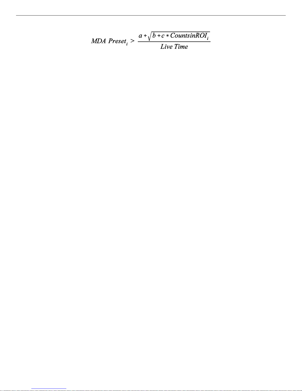
794380D / 0914 4. FIRMWARE COMMANDS AND RESPONSES
The calculation is performed once every 30 seconds with i starting at 0 and advancing
through each of up to 20 unique MDA presets. i only advances once the preset has been met.
Note that a, b, and c are the same for each of the unique presets. Only the ROI range and the
MDA preset change when i advances. Once i reaches 20 or MDAPreset
equals 0, the
i
acquisition terminates.
SET_MDA_PRESET MDAPreset,[PeakNumber]
Sets the MDAPreset PeakNumber value as shown in the equation in the SET_MDA_CO EF
description above. MDAPreset is usually the product of the desired MDA, the yield and the
efficiency. PeakNumber is a parameter that specifies which of up to 20 (0–19) MDA presets
to change. If PeakNumber is om itted in the set command, all MDA preset values will be set
to 0 (disabled), and the supplied value will be applied to MDA Preset 0. This provides compatibility software that only supports the one-nuclide MDA method implemented in some
MCBs.
SET_MODE_LIST
Sets the DSPEC Pro to list mode. See also SHOW_MODE.
SET_MODE_PHA
Sets the mode to PHA.
SET_MODE_SAMPLE
Starts the InSight Virtual Oscilloscope mode.
SET_MODE_ZDT mode
Sets the ZDT mode. LIST_MODE_ZDT can be used to determine which modes are valid.
Mode 0 (standard) indicates that a normal and corrected spectrum should be stored. Mode 1
(enhanced) indicates that an error and a corrected spectrum should be stored. ENABLE_ZDT
must be issued to turn on ZDT mode.
SET_OUTPUT [port, value]
This sends the value to the port. This command can be issued without entries for port and
value because the DSPEC Pro has only one port. If you wish to specify a port number, it
must be zero for this unit. See also SHOW_OUTPUT. See also STEP_OUTPUT.
67
Page 78

DSPEC Pro® Digital Gamma-Ray Spectrometer User’s Manual 794380D / 0914
SET_OUTPUT_HIGH [output-num]
Sets the Change Sample output to the high level. The DSPEC Pro has only one samplechanger BNC, therefore, if you include a value for output-num, it m ust be zero (output-num
is provided for compatibility with other O R TEC instruments). See also ST EP_OUTPUT.
SET_OUTPUT_LOW [output-num]
Sets the Change Sample output to the low level. The DSPEC Pro has only one samplechanger BNC, therefore, if you include a value for output-num, it m ust be zero (output-num
is provided for compatibility with other O R TEC instruments). See also ST EP_OUTPUT.
SET_PEAK_PRESET count
Sets the ROI peak preset to the specified count. During data acquisition when the contents of
any channel of a device that has the ROI flag set reaches the peak preset count, the preset is
complete and the acquisition is stopped. The actual num ber of counts in the ROI peak may
exceed the preset value by a small number of counts due to the pipelined architecture of the
DSPEC Pro. Setting a peak preset to 0 counts disables the preset. The peak preset may be set
to from 0 (disabled) to 2147483647 counts. See also CLEAR_PRESETS and
SHOW_PEAK_PRESET.
SET_PZ num
This sets the pole zero to num, which must be between 0 and 4095. See also ENABL E_PZ_
AUTO, SHOW_PZ, and DISABLE_PZ_AUTO.
SET_RADIX_BINARY
Not used; included for backward compatibility.
SET_ROI start_chan,number_of_chans
Sets the ROI flags for the specified channels. This command can be used multiple times to
set ROI flags without affecting previously set flags. ROI flags specify channels within a
device that are considered for ROI integral and ROI peak presets.
SET_ROI_MDA start,numchans, [PeakNumber]
Sets the region to use to compute the gross counts in the MDA calculation. PeakNumber is
an optional parameter (assumed 0 if not present) that specifies w hich of up to 20 (0–19)
MDA Presets to change.
SET_ROI_SAMPLE num
Selects which control signals are displayed as an ROI on the captured waveform. Only a
single bit can be turned on at a time. The following signals can be selected with the
associated bit.
Bit 0: Pileup reject.
68
Page 79

794380D / 0914 4. FIRMWARE COMMANDS AND RESPONSES
Bit 1: Negative baseline threshold.
Bit 2: Baseline restorer gate.
Bit 3: Positive baseline threshold.
Bit 4: Busy.
Bit 5: Gate.
Bit 6: Reserved.
Bit 7: Peak detect.
Bit 8: Reserved.
SET_ROI_UNCERTAINTY start, chans
Sets the region to be used for the uncertainty preset calculation. See also SHOW_ROI_
UNCERTAINTY.
SET_SEGMENT
Not used; included for backward compatibility.
SET_SHAP_FLAT value
Sets the width of the flattop to value. Value is in microseconds, ranging from 0.3 to 2.4 µs in
steps of 0.1. See also SHOW_SHAP_FLAT.
SET_SHAP_RISE value
Sets the rise time to value. Value is in microseconds, ranging from 0.8 to 23 µs in steps of
0.2. See also SHOW_SHAP _RISE.
SET_SHUTDOWN index
Used in conjunction with the LIST_SHUTDOWN command to set the high voltage
shutdown setting. Index specifies a position in the list of legal shutdown settings which were
displayed with the LIST_SHUTDOWN command.
Example
:
SET_SHUT 0 Sets the SHUTDOWN to TTL.
SET_SHUT 1 Sets the SHUTDOWN to ORTEC.
SET_SHUT 2 Sets the SHUTDOWN to SMART.
SET_SHUTDOWN_ORTEC
This sets the bias shutdown mode to OR TEC.
SET_SHUTDOWN_SMART
Sets the bias shutdown mode to SMART.
SET_SHUTDOWN_TTL
This sets the bias shutdown mode to TTL.
69
Page 80

DSPEC Pro® Digital Gamma-Ray Spectrometer User’s Manual 794380D / 0914
SET_THRESHOLD_NEGATIVE value
Sets the negative threshold to value. The negative threshold is normally set automatically by
the DSPEC Pro. See also ENABLE_ THRESHOLD_AUTOMATIC and
SHOW_THRESHOLD_NEGATIVE.
SET_THRESHOLD_POSITIVE value
Sets the positive threshold to value. The positive threshold is normally set automatically by
the DSPEC Pro. See also ENABLE_THRESHOLD_AUTOMATIC and
SHOW_THRESHOLD_POSITIVE.
SET_TIME hour,min,sec
Sets the time stored in the battery backed-up system clock to the specified values. hour can
be any value from 0–23; min and sec can be any value from 0–59. The current date and time
are stored for a device when an acquisition is started. See also SHOW_TIME, SET_DATE,
SHOW_DATE, SET_TIME_START, and SHOW_TIME_START.
SET_TIME_ETP value
Sets the Enhanced Throughput Mode protection time, in microseconds. value ranges from
0.1 µs to 200 µs in 25-ns increments.
Example:
SET_TIME_ETP 50 Set the protection time to 50 µs.
SET_TIME_START hour,min,sec
Sets the start time to the specified values. Normally the start date and time are set
automatically whenever a device is started with the START command. See also
SHOW_TIME_START, SET_DATE_START, SHOW_DATE_START, SET_DATE, and
SET_TIME.
SET_TRIGGER_POLARITY polarity
This sets the polarity of the input trigger for the sample changer (which occurs on the
SAMPLERDYIN BNC) to zero or 1. Zero means it is negative-edge triggered and triggers
on a high-to-low transition; 1 means the trigger is positive-edged and triggers on a low-tohigh transition. See also TRIGGER, ENABLE_TRIGGER, DISABLE_TRIGGER,
SHOW_TRIGGER, and SHOW_TRIGGER_POLARITY.
SET_TRUE ticks
Sets the true-time counter to the specified number of ticks. T he number represents true time
in units of 20 ms (50 ticks/sec). Normally this value is set by the DSPEC Pro during data
acquisition. See also CLEAR_COUNTER and SHOW_TRUE.
70
Page 81

794380D / 0914 4. FIRMWARE COMMANDS AND RESPONSES
SET_TRUE_PRESET ticks
Sets the true-time preset to the specified number of ticks (20 ms/tick). During data acquisition when the true-time counter reaches the preset number of ticks, the preset is complete
and the acquisition is stopped. Setting a true-time preset to 0 ticks disables the preset. See
also CLEAR_PRESETS and SHOW_TRUE_PRESET.
SET_ULD value
This sets the upper level discriminator to value, in channels.
SET_UNCERTAINTY_PRESET percent
Sets the uncertainty preset to the specified value in percent. Percent is a floating point value
from 0–99.9999. See also SHOW_UNCERTAIN TY_PRESET.
SET_WINDOW [start, length]
Sets the window of interest to the specified start channel and number of channels. The channels of spectral data in the window of interest are affected by com mands such as CLEAR,
SET_DATA, and WRITE. If neither start nor length is provided, the w indow is set to the
maximum size allowed by the conversion gain specified. The window of interest is always
set to the maximum size after a SET_DEVICE command or a SET_SEGMENT command.
SET_ZERO_ADJUSTMENT value
Sets the zero stabilization adjustment to an arbitrary value from !65535 to 65535. The
total range of the adjustment value represents ±256 channels. This adjustment is usually
only made by the gain stabilizer, and reset to 0 with the INITIALIZE_ZERO_
STABILIZATION command. See also SHOW_ZERO_ADJUSTMENT.
SET_ZERO_CHANNEL chan
Sets the center channel for the stabilizer zero peak. If a zero channel is chosen such that the
beginning channel or ending channel would be below channel 0 or above the maximum
channel, as determined by the conversion gain, the zero peak width is reduced until the peak
fits the device boundaries. A zero channel and width must be set before zero stabilization
can be enabled. See also ENABLE_ZERO_STABILIZATION.
SET_ZERO_WIDTH chans
Sets the width in channels for the stabilizer zero peak. The zero width must be chosen such
that the beginning channel is no lower than channel 0 and the ending channel is no higher
than the maximum channel as determined by the conversion gain. The zero channel and
width must be set before zero stabilization can be enabled. The absolute minimum width for
the zero peak is 3 channels, and the absolute maxim um width for the zero peak is 256 channels in Gauss mode. In point mode there is no maximum peak width, though the chosen
width must allow the peak to fit within the device’s channel limits as stated above.
71
Page 82

DSPEC Pro® Digital Gamma-Ray Spectrometer User’s Manual 794380D / 0914
SHOW_ACTIVE
Returns a 1 if the DSPEC Pro is active (i.e., acquiring spectral data) or 0 if it is not active.
Responses:
$C00000087<CR> Not active.
$C00001088<CR> Active.
SHOW_BLRE
Shows the baseline restorer time constant in microseconds. See also SET_BLRE.
Responses:
BLUE 000000000000091 Time constant is 91 µs.
SHOW_BLRE_AUTOMATIC
Shows whether automatic selection of the baseline restorer constant is off or on.
Responses:
$IT<CR> Automatic baseline is enabled.
$IF<CR> Automatic baseline is disabled.
SHOW_CONFIGURATION
Returns a record that indicates the hardware configuration of the MCB. The record contains
information about the number of segments in an MCB device (always 1 for the DSPEC Pro),
and the current conversion gain for each segment. The record is organized as follows:
$J1638400001aaaaa00000[65 zeros here for total of 75 zeros]00000ccc
where aaaaa represents the conversion gain for the one and only segment in the currently
selected device, and ccc represents the record checksum. See the section on response records
in this chapter for more information about response records and checksums.
SHOW_CONFIGURATION_MASK
Returns two masks, the first of which can be “anded” with data from the MCB to clear the
ROI bit from the data. When the second mask value is “anded” with data from the MCB, the
data bits are removed and only the ROI bit remains.
Response
:
CONF_MAS K 02147483647 02147483648
SHOW_CORRECTION_FLAT
Shows the flattop correction value. See also SET_CORR_FLAT.
Responses:
CORR_FLAT 000000000000000
72
Page 83

794380D / 0914 4. FIRMWARE COMMANDS AND RESPONSES
SHOW_CRM
Returns the current reading of the count-rate meter.
Response
:
$G0000050781096 Current input count rate is 50781 counts/s.
SHOW_DATA_APPLICATION “string”
If string matches “string1" in a previous SET_DATA_APPLICA TION command, then
string2 from that command is returned. The response is a $F record.
SHOW_DATE
Returns the day, month, and year of the current date as maintained in the battery-backed-up
real time clock, in the form dddmmmyyy. The day is returned as a 3-digit integer number
from 001 to 031, month as a 3-digit integer number from 001 to 012, and year as a 3-digit
integer number from 000 to 099. See also SET_DATE_START.
Responses:
$N001001088052<CR> Date reported as Jan 1, 1988.
... ...
$N031012099059<CR> Date reported as Dec 31, 1999.
$N001001000036<CR> Date reported as Jan 1, 2000.
... ...
$N031012087056<CR> Date reported as Dec 31, 2087.
SHOW_DATE_START
Returns the day, month and year of the acquisition start date in the form dddmmmyyy. The
day is returned as a 3-digit integer number from 001–031, month as a 3-digit integer number
from 001–012, and year as a 3-digit integer number from 000–099. See also
SET_DATE_START.
Responses:
$N001001088052<CR> Date reported as Jan 1, 1988.
... ...
$N031012099059<CR> Date reported as Dec 31, 1999.
$N001001000036<CR> Date reported as Jan 1, 2000.
... ...
$N031012087056<CR> Date reported as Dec 31, 2087.
SHOW_DELAY_COLLECTION
Shows the width of the PUR signal setting. See also SET_DELAY_ COLLECTION.
Responses:
DEL_COLL 0000000000001.6
73
Page 84

DSPEC Pro® Digital Gamma-Ray Spectrometer User’s Manual 794380D / 0914
SHOW_DELAY_SAMPLE
Shows the Delay Sam ple setting. See also SET_DELAY_SAMPLE.
Responses:
$C00003090 The sample number is 00003, and 090 is the checksum.
SHOW_DET_SNUM
This comma nd responds with the detector serial number stored in the SMART-1 DIM.
Response:
$FP40175 Serial number P40175.
SHOW_DET_VERSION
Returns the DIM firmware version.
Examples:
$FNAID000 NaI DIM firmware version.
$FSMDT000 SMART-1 firmware version.
SHOW_DEVICE
Shows the currently selected device. Always 1 for DSPEC Pro.
SHOW_DISPLAY
Not used; included for backward compatibility.
SHOW_ETP
Reports if Enhanced Throughput Mode is enabled.
Responses:
$IF Enhanced Throughput Mode disabled.
$IT Enhanced Throughput Mode enabled.
SHOW_FEATURES
Responds with four 32-bit masks indicating which features are present in the MCB. See
Appendix 3.3 for a complete description of each bit in the mask.
Example Response
:
FEATURES 02285062207 02014941185 00000000000 00000000000
SHOW_GAIN_ADJUST
Returns the gain-stabilizer amplifier setting.
SHOW_GAIN_CHANNEL
Reports the current center channel for the stabilizer gain peak. See also
SET_GAIN_CHANNEL.
74
Page 85

794380D / 0914 4. FIRMWARE COMMANDS AND RESPONSES
Responses:
$C00000087<CR> Gain channel has not been set.
$C00002089<CR> Gain channel is channel 2 (lowest possible channel).
... ...
$C16382107<CR> Gain channel is channel 16382 (highest possible
channel).
SHOW_GAIN_COARSE
Returns the coarse gain for the DSPEC Pro internal amplifier. In operation, the resulting
signal gain is the product of the coarse gain, the fine gain, and the super-fine gain (used by
stabilizer). The coarse gain is returned in terms of an integer gain multiplier.
Responses:
$C00001088<CR> Coarse gain reported as 1.
$C00002089<CR> Coarse gain reported as 2.
$C00004091<CR> Coarse gain reported as 4.
$C00008095<CR> Coarse gain reported as 8.
$C00016094<CR> Coarse gain reported as 16.
$C00032092<CR> Coarse gain reported as 32.
SHOW_GAIN_CONVERSION
This comma nd returns the conversion gain.
Responses:
$C00512095<CR> Conversion gain reported as 512 channels.
$C01024094<CR> Conversion gain reported as 1024 channels.
$C02048101<CR> Conversion gain reported as 2048 channels.
$C04096106<CR> Conversion gain reported as 4096 channels.
$C08192107<CR> Conversion gain reported as 8192 channels.
$C16384109<CR> Conversion gain reported as 16384 channels.
SHOW_GAIN_FINE
Returns the current fine gain setting. See SET_GAIN_FINE.
Sample Response:
GAIN_FINE 000000.70000203 Fine gain is set to 0.7.
SHOW_GAIN_POLARITY
Returns the polarity of the amplifier input as $F records.
Responses:
$FNEG<CR> The amplifier input is set to negative.
$FPOS<CR> The amplifier input is set to positive.
75
Page 86

DSPEC Pro® Digital Gamma-Ray Spectrometer User’s Manual 794380D / 0914
SHOW_GAIN_STABILIZATION
Reports the state of gain peak stabilization. See also ENABLE_GAIN_STABILIZATION
and DISABLE_GAIN_STABILIZATION.
Responses:
$IT<CR> Gain stabilization is currently enabled.
$IF<CR> Gain stabilization is currently disabled.
SHOW_GAIN_WIDTH
Reports the current width for the stabilizer gain peak. See also SET_GAIN_WIDTH,
SET_GAIN_CHANNEL, and SHOW_GAIN_CHANNEL.
Responses:
$C00001088<CR> Gain width has not been set.
$C00003089<CR> Gain width is 3 channels (lowest possible width).
... ...
$C00256100<CR> Gain width is 256 channels (highest possible width in
Gauss mode).
SHOW_GATE
Reports the current mode of operation of the ADC gate input. See also SET_GATE_OFF,
SET_GATE_COINCIDENT, and SET_GATE_ANTICOINCIDENT.
Responses:
$FOFF<CR> Reports the ADC gate is off or ignored.
$FCOI<CR> Reports the ADC gate is in coincident mode.
$FANT<CR> Reports the ADC gate is in anticoincident mode.
SHOW_HV
Reports the current high voltage and the status of the high voltage power supply in the form
$Dvvvvvsssssccc.
Where vvvvv represents the current output voltage if the high voltage is enabled, or the rearpanel high voltage setting if the high voltage is disabled. sssss represents the status of the
high voltage bias supply as a 16-bit decimal number with the following bit definitions:
Bit 0 (LSB): Bias supply polarity (0 = positive, 1 = negative).
Bit 1: Bias supply overload (0 = overload, 1 = normal).
Bit 2: High voltage enabled (0 = disabled, 1 = enabled).
Example Responses:
$D0200000003077<CR> 2000 V, negative, not overloaded, disabled.
$D0200000002076<CR> 2000 V, positive, not overloaded, disabled.
$D0200000007082<CR> 2000 V, negative, not overloaded, enabled.
SHOW_HV_ACTUAL
Returns the value of HV actually on the detector.
76
Page 87

794380D / 0914 4. FIRMWARE COMMANDS AND RESPONSES
SHOW_HV_DIM
Indicates whether HV_DIM is enabled or disabled.
SHOW_HV_HEALTH
Returns the status of the state of health for the detector as reported by the DIM or SMART-1.
SHOW_HV_POLARITY
This returns the HV polarity defined in the DIM as a $F record.
Responses:
$FNEG<CR> The HV is set to negative.
$FPOS<CR> The HV is set to positive.
SHOW_HV_RECOMMEND
Returns HV in volts, in ASCII, from SMART-1 detectors.
SHOW_HV_TARGET
Under normal operation, the HV will go to this value when the HV is enabled. Reports the
current HV setting (see SET_HV) and the status of the HV power supply in the form:
$Dvvvvvsssssccc<CR>
where vvvvv represents the HV setting, and sssss represents the status of the HV bias supply
as a 16-bit decimal number with the following bit definitions:
Bit 0 (LSB): Bias supply polarity (0 = positive, 1 = negative).
Bit 1: Bias supply overload (0 = overload, 1 = normal).
Bit 2: HV enabled (0 = disabled, 1 = enabled).
Example Responses:
$D0200000003077<CR> 2000 V, negative, not overloaded, disabled.
$D0200000002076<CR> 2000 V, positive, not overloaded, disabled.
$D0200000007082<CR> 2000 V, negative, not overloaded, enabled.
SHOW_ID
Reports the sample ID string as was previously set by the SET_ID command.
Example Responses:
$FSite 123<CR> ID set to “Site 123".
$FSample 123456789<CR> ID set to “Sample 123456789".
SHOW_INPUT [0]
Reports the state of the Sample Ready input.
Responses:
$C00000087<CR> Sample Ready input is low.
$C00001088<CR> Sample Ready input is high.
77
Page 88

DSPEC Pro® Digital Gamma-Ray Spectrometer User’s Manual 794380D / 0914
SHOW_INTEGRAL [start_chan,number_of_chans]
Reports the sum of the specified group of spectral data channels. If start_chan and
number_of_chans is not provided, SHOW_INTEGRAL reports the sum of all channels in the
currently selected window that have their ROI flag set.
Responses:
$G0000000000075<CR> Integral reported as 0.
... ...
$G4294967294131<CR> Integral reported as 4294967294.
$G4294967295132<CR> Integral reported as greater than or equal to
4294967295 (maximum reportable value).
SHOW_INTEGRAL_PRESET
Reports the current ROI integral preset value. For more information about the ROI integral
preset, see SET_INTEGRAL_PRESET. See also SHOW_INTEGRAL.
Responses:
$G0000000000075<CR> Integral preset reported as 0.
... ...
$G4294967295132<CR> Integral reported as 4294967295.
SHOW_INTEGRAL_REMAINING
Reports the current ROI integral remaining value. For more information about the ROI
integral remaining, see SET_INTEGRAL_REMAINING. See also SHOW_INTEGRAL.
Responses:
$G0000000000075<CR> Integral remaining reported as 0.
... ...
$G4294967295132<CR> Integral reported as 4294967295.
SHOW_LENGTH_SAMPLE
Reports the number of points in the Insight mode waveform.
Response:
$C01000088 1000 points in the waveform.
SHOW_LFR
Tells whether LFR mode is enabled.
Responses:
$IF LFR mode disabled.
$IT LFR mode enabled.
SHOW_LIVE
Reports the contents of the live-time counter in units of 20 ms (50 ticks/s). See also
CLEAR_COUNTER and SET_LIVE.
78
Page 89

794380D / 0914 4. FIRMWARE COMMANDS AND RESPONSES
Responses:
$G0000000000075<CR> Live time reported as 0 ticks.
$G0000000001076<CR> Live time reported as 1 tick (20 ms).
... ...
$G4294967295132<CR> Live time reported as 4294967295 ticks (over 23000
days).
SHOW_LIVE_PRESET
Reports the current live-time preset in units of 20 ms (50 ticks/s). See also CL EAR_
PRESETS and SET_LIVE_PRESET.
Responses:
$G0000000000075<CR> Live-time preset reported as disabled.
$G0000000001076<CR> Live-time preset reported as 1 tick.
... ...
$G4294967295132<CR> Live-time preset reported as 4294967295 ticks.
SHOW_LIVE_REMAINING
Reports the current live-time remaining in units of 20 ms (50 ticks/s). See also SET_LIVE_
REMAINING.
Responses:
$G0000000000075<CR> Live-time remaining reported as disabled.
$G0000000001076<CR> Live-time remaining reported as 1 tick.
... ...
$G4294967295132<CR> Live-time remaining reported as 4294967295 ticks.
SHOW_LLD
Shows the lower level discriminator setting. See also SET_LLD.
Responses:
$C00050092 The LLD is 50.
SHOW_MDA [PeakNumber]
Reports current MDA for the MDA Preset selected by PeakNumber. PeakNumber is
assumed to be 0 if not supplied.
Example response:
MDA 0000000000010.7
SHOW_MDA_COEF
Reports the current settings for coeffficients a, b, and c used for the MDA calculation. See
SET_MDA_COEF.
79
Page 90

DSPEC Pro® Digital Gamma-Ray Spectrometer User’s Manual 794380D / 0914
Example Responses:
MDA_COEF 000000000002.71 000000000000000 00000021.700001
Coefficient a = 2.71, b = 0, and c = 21.7.
SHOW_MDA_PRESET [PeakNumber]
Reports MDA preset PeakNumber. If PeakNumber is omitted, 0 is assumed.
Example Response:
MDA_PRES 0000000000025.7
SHOW_MODE
Reports the current mode of operation (PHA, List, or Sample [InSight Virtual Oscilloscope]). See also SET_MODE_PH A and SET_MODE_SAMPLE .
Responses:
$FPHA<CR> PHA mode.
$FLIS<CR> List mode.
$FSAM<CR> Sample mode (InSight).
SHOW_MODE_ZDT
Reports the current ZDT mode. See SET_MODE_ZDT.
Responses:
MODE_Z DT 00000 Mode 0 selected (normal and corrected).
MODE_Z DT 00001 Mode 1 selected (error and corrected).
SHOW_MONI_LABEL num
Returns with an ASCII string label designation for the state-of-health parameter for num.
SHOW_MONI_MAX
Returns with the number of state-of-health values available for viewing.
SHOW_MONI_VALUE num
Returns with an ASCII representation of the value for the state-of-health parameter.
SHOW_NAI
Indicates whether ENABLE_NAI has been sent. Responses are true and false.
Responses:
$IT<CR> NaI mode enabled.
$IF<CR> NaI mode disabled.
SHOW_NEXT
Used in conjunction with the SHOW _ROI command, SHOW_NE XT reports the next
continuous group of channels that have the ROI flag set. The response is of the form:
80
Page 91

794380D / 0914 4. FIRMWARE COMMANDS AND RESPONSES
$Dsssssnnnnnccc<CR>
where sssss represents an integer number that is the number of the first channel of the “next”
group of channels that all have their ROI bit set, and nnnnn represents an integer number
that is the number of channels in the group. If no more channels have their ROI bit set,
SHOW_NEXT returns a first channel of 0 and a number of channels of 0. The SHOW_ROI
command is used to report the “first” group of channels that all have their ROI bit set.
Example Responses:
$D0100000050078<CR> Next ROI group starts at channel 1000 and is 50
channels long.
$D0215000150086<CR> Next ROI group starts at channel 2150 and is 150
channels long.
$D0000000000072<CR> No other ROI groups to report.
SHOW_OUTPUT [0]
Reports the status of the “Change Sample” output port. The output port status is reported as
a 16-bit number that is 0 or 1, depending on the level last set by a SE T_OUTPUT_HIGH or
SET_OUTPUT_LOW command.
Responses:
$C00000087<CR> Change Sample output currently low.
$C00001088<CR> Change Sample output currently high.
SHOW_OVERFLOW_PRESET
Reports the state of the overflow preset.
Responses:
$IT<CR> Overflow preset enabled.
$IF<CR> Overflow preset disabled.
SHOW_PEAK
This command returns the contents of the ROI channel with the largest number of counts. An
ROI channel is a channel that has the ROI flag set. The maxim um possible value is
2147483647, which is the maximum num ber of counts that can be stored in a 31-bit channel.
Responses:
$G0000000000075<CR> Maximum count in an ROI channel is zero or no ROI
channels were found.
$G0000000001076<CR> Maximum count in an ROI channel is 1.
... ...
$G2147483646120<CR> Maximum count in an ROI channel is 2147483646.
$G2147483647121<CR> Maximum count in an ROI channel is 2147483647.
81
Page 92

DSPEC Pro® Digital Gamma-Ray Spectrometer User’s Manual 794380D / 0914
SHOW_PEAK_CHANNEL
This command returns the number of the ROI channel with the largest number of counts. An
ROI channel is a channel that has the ROI flag set. The lowest number ROI channel with the
largest count is reported if more that one channel contains the largest number of counts.
Channel 16383 is the highest numbered channel in any device.
Responses:
$C00000087<CR> Maximum count was found in channel 0 or no ROI channels
were found.
$C00001088<CR> Maximum count w as found in channel 1.
... ...
$C16382107<CR> Maximum count was found in channel 16382.
$C16383108<CR> Maximum count was found in channel 16383.
SHOW_PEAK_PRESET
Reports the value of the ROI peak preset. See SET_PEAK_PRESET for information about
the ROI peak preset.
Responses:
$G0000000000075<CR> Peak preset disabled.
$G0000000001076<CR> Peak preset set to 1 count.
$G2147483646120<CR> Peak preset set to 2147483646 counts.
$G2147483647121<CR> Peak preset set to 2147483647 counts.
SHOW_PZ
Displays the PZ setting. See also SET_PZ.
Responses:
PZ_ENA 002200 Pole zero enabled and set to 2200.
PZ_DIS 001000 Pole zero disabled and set to 1000.
SHOW_PZ_AUTOMATIC
Shows the state of the automatic PZ. See also SET_PZ_AUTOMATIC.
Responses:
$IT<CR> Pole zero enabled.
$IF<CR> Pole zero disabled (TRP).
SHOW_RADIX
SHOW_RATE_ZDT
SHOW_REMOTE
Not used; included for backward compatibility.
SHOW_RENH
Reports if Resolution Enhancer mode is enabled.
82
Page 93

794380D / 0914 4. FIRMWARE COMMANDS AND RESPONSES
Responses:
$IF Resolution Enhancer mode disabled.
$IT Resolution Enhancer mode enabled.
SHOW_ROI
Used in conjunction with the SHOW_NEXT com mand, SHOW_ROI reports the first continuous group of channels that have the ROI flag set. The response is of the form:
$Dsssssnnnnnccc<CR>
where sssss represents an integer number that is the number of the first channel of the “first”
group of channels that all have their ROI bit set, and nnnnn represents an integer number
that is the number of channels in the group. The SHOW_NEXT command is used to report
the “next” group of channels that all have their ROI bit set.
Responses:
$D0100000050078<CR> First ROI group starts at channel 1000 and is 50 channels
long.
$D0215000150086<CR> First ROI group starts at channel 2150 and is 150 channels
long.
$D0000000000072<CR> No ROI groups to report.
SHOW_ROI_MDA
Reports the start channel and number of channels used in the MDA preset calculation.
Example Response
:
$D0700000050ccc Calculation is performed on channels 7000–7049.
SHOW_ROI_SAMPLE
Displays the ROI Sample setting. See also SET_ROI_SAMPLE.
Responses:
$C00001088
SHOW_ROI_UNCERTAINTY
Reports the start channel and number of channels used in the uncertainty preset calculation.
See also SET_ROI_UNCERTAINTY.
Response:
$D0700000050ccc Calculation is performed on channels 7000–7049.
SHOW_SEGMENT
Returns the current segment number. Always 1 for the DSPEC Pro.
SHOW_SHAPE_CUSP
Not used by the DSPEC Pro; included for backward compatibility.
83
Page 94

DSPEC Pro® Digital Gamma-Ray Spectrometer User’s Manual 794380D / 0914
SHOW_SHAP_FLAT
Reports the width of the flattop in µs. See also SET_SHAP_FLAT.
Responses:
SHAP_FLAT 0000000000001.2
SHOW_SHAP_RISE
Displays the rise-time setting in µs. See also SET_SHAP_RISE.
Responses:
SHAP_RISE 0000000000003.2
SHOW_SHUTDOWN
Shows the type of HV shutdown selected.
Responses:
$FORT ORTEC mode selected.
$FTTL TTL mode selected.
$FSM1 SMART-1 m ode selected.
SHOW_SHUT_ACTUAL
Returns the current status of the bias remote shutdown input signal. This command is valid
whether the bias supply is turned on or off.
Responses:
$IT Shutdown is active (supply is shut down or can’t be
turned on).
$IF Shutdown is inactive (supply is on or can be turned
on).
SHOW_SNUM
Responds with a $F record indicating the serial number of the DSPEC Pro
Response:
$F100 Serial number = 100.
SHOW_STATUS
Returns system status information in the following format:
$Mllllllllllttttttttttaaaaahhhhhccc<CR>
where llllllllll represents the live time as returned by the SHOW_LIVE command, tttttttttt
represents the true time for the current device as returned by the SHOW_TRUE command,
aaaaa represents the active device mask as returned by the SHOW_ACTIVE_DEVICES
command, and hhhhh represents the hardware status, which is an ASCII representation of a
16 bit decimal number with the following bit definitions:
Bit 0 (LSB): Bias supply polarity (0=positive, 1=negative)
Bit 1: Bias supply overload (0=overload, 1=normal)
84
Page 95

794380D / 0914 4. FIRMWARE COMMANDS AND RESPONSES
Bit 2: High voltage enabled (0=disabled, 1=enabled)
Bit 3: Unused
Bit 4: Amplifier PZ’d since initialization (0=normal,
1=needs PZ’ing)
Bit 5 Optimization since initialization (0=norma l,
1=needed)
Bits 6–7: Unused
Bit 8: Amplifier automatic PZ (1=Auto PZ in progress,
0=normal)
Bit 9: Optimization (0=normal, 1=in progress)
Bits 10–14: Unused
Bit 15 (MSB): Reserved
SHOW_THRESHOLD_AUTOMATIC
See also SET_THRESHOLD_AUTOMATIC.
Responses:
$IT<CR> Automatic threshold is enabled.
$IF<CR> Automatic threshold is disabled.
SHOW_THRESHOLD_NEGATIVE
See also SET_THRESHOLD_NEGATIVE.
Responses:
THR_NEG 0000379791 Negative threshold is 379791.
SHOW_THRESHOLD_POSITIVE
See also SET_THRESHOLD_POSITIVE.
Responses:
THR_POS 00000126811 Positive threshold is 126811.
SHOW_TIME
Reports the time from the battery backed-up system clock in the form:
$Nhhhmmmsssccc<CR>
where hhh represents a 3-digit integer hour (0–23), mmm represents a 3-digit integer minute
(0–59), and sss represents a 3-digit integer second (0–59). See also SET_TIME,
SET_DATE, and SHOW_DATE.
Example Responses:
$N010054017052<CR> Time returned 10:54:17 (10 h, 54 min, 17 s).
$N020013037050<CR> Time returned 20:13:37 (20 h, 13 min, 37 s).
85
Page 96

DSPEC Pro® Digital Gamma-Ray Spectrometer User’s Manual 794380D / 0914
SHOW_TIME_ETP
Returns the current Enhanced Throughput Mode protection time.
Response:
TIME_ETP 0000000000012.8 Protection time is set to 12.8 µs.
SHOW_TIME_START
Reports the time of the last START command in the form
$Nhhhmmmsssccc<CR>
where hhh represents a 3-digit integer hour (0 through 23), mmm represents a 3-digit integer
minute (0 through 59) and sss represents a 3-digit integer second (0 through 59). See also
SET_TIME_START, SET_DATE_START, and SHOW_DATE_START.
Example Responses:
$N010054017052<CR> Time returned 10:54:17 (10 h, 54 min, 17 s).
$N020013037050<CR> Time returned 20:13:37 (20 h, 13 min, 37 s).
SHOW_TRIGGER
Tells whether the trigger is enabled or disabled. See also ENABLE_TRIGGER.
Responses:
$IF Trigger disabled.
$IT Trigger enabled.
SHOW_TRIGGER_POLARITY
This returns the polarity setting of the input trigger for the sample changer (1 means the
trigger is positive-edged and triggers on a low-to-high transition; 0 means it is negative-edge
triggered and triggers on a high-to-low transition). See also TRIGGER, ENABLE_
TRIGGER, DISABLE_TRIGGER, SHOW_TRIGGER, and SET_TRIGGER_POLARITY.
Responses:
$FNEG<CR> The HV is set to negative.
$FPOS<CR> The HV is set to positive.
SHOW_TRIGGER_SAMPLE
Reports the trigger source in Insight Mode.
Responses:
$F0LLD LLD is source.
$F1PKD Peak-detect is source.
$F2RANDOM Trigger happens randomly.
$F3Gate Gate Input triggers the waveform.
SHOW_TRIGGER_SPECIAL
Not used; included for backward compatibility.
86
Page 97

794380D / 0914 4. FIRMWARE COMMANDS AND RESPONSES
SHOW_TRUE
Reports the contents of the true-time counter in units of 20 ms (50 ticks/s). See also
CLEAR_COUNTER and SET_TRUE.
Responses:
$G0000000000075<CR> True time reported as 0 ticks.
$G0000000001076<CR> True time reported as 1 tick (20 ms).
... ...
$G4294967295132<CR> True time reported as 4294967295 ticks (over 23000
days).
SHOW_TRUE_PRESET
Reports the current true-time preset in units of 20 ms (50 ticks/s). See also
CLEAR_PRESETS and SET_TRUE_PRESET.
Responses:
$G0000000000075<CR> True time preset reported as disabled.
$G0000000001076<CR> True time preset reported as 1 tick.
... ...
$G4294967295132<CR> True time preset reported as 4294967295 ticks.
SHOW_TRUE_REMAINING
Reports the current true time remaining in units of 20 milliseconds (50 ticks per second). See
also SET_TRUE_REMAINING.
Responses:
$G0000000000075<CR> True time remaining reported as disabled.
$G0000000001076<CR> True time remaining reported as 1 tick.
... ...
$G4294967295132<CR> True time remaining reported as 4294967295 ticks.
SHOW_ULD
Returns the value of the ULD in channels, as a $C record.
SHOW_UNCERTAINTY
Returns the current value of the uncertainty for the peak in the uncertainty preset. See also
SET_UNCERTAINTY.
Responses:
UNCE 0000000000008.5 Uncertainty of the peak is 8.5%.
87
Page 98

DSPEC Pro® Digital Gamma-Ray Spectrometer User’s Manual 794380D / 0914
SHOW_UNCERTAINTY_PRESET
Returns the current uncertainty preset setting. See also SET_UNCERTAINTY_PRESET.
Responses:
UNCE_PRES 000000000000000 No preset.
UNCE_PRES 0000000000008.5 Preset set to 8.5%.
SHOW_VERSION
Reports the DSPEC Pro firmware version number in the form
Fmmmm-vvv<CR>
where mmmm is a 4-character model designator and vvv is a 3-character version designator.
Example Responses:
$FDSPR–002<CR> Model DSPEC Pro firmware Ve rsion 2 reported.
SHOW_WINDOW
Reports the start channel and number of channels in the window of interest, in the form
$Dxxxxxyyyyyccc<CR>
where xxxxx is the start channel (0–16383) and yyyyy is the number of channels (1–16384).
See SET_WINDOW for more information about the window of interest.
Example Responses:
$D0000016384094<CR> Window of interest reported as starting at channel 0
and continuing for 16384 channels.
$D0000008192092<CR> Window of interest reported as starting at channel 0
and continuing for 8192 channels.
$D0819208192112<CR> Window of interest reported as starting at channel
8192 and continuing for 8192 channels.
SHOW_ZDT
Reports if ZDT mode is enabled.
Responses:
$IF ZDT mode disabled.
$IT ZDT mode enabled.
SHOW_ZERO_ADJ
Returns the value of the zero offset for the zero stabilizer.
SHOW_ZERO_CHANNEL
Reports the center channel for the stabilizer zero peak. See also SET_ZERO_CHANNEL,
SET_ZERO_WIDTH, and SHOW_ZERO_WIDTH.
88
Page 99

794380D / 0914 4. FIRMWARE COMMANDS AND RESPONSES
Responses:
$C00000087<CR> Zero channel has not been set.
$C00002089<CR> Zero channel is channel 2 (lowest possible channel).
... ...
$C16382107<CR> Zero channel is channel 16382 (highest possible channel).
SHOW_ZERO_STABILIZATION
Reports the state of zero peak stabilization. See also ENABLE_ZERO_STABILIZATION
and DISABLE_ZERO_STABILIZATION.
Responses:
$IT<CR> Zero stabilization is currently enabled.
$IF<CR> Zero stabilization is currently disabled.
SHOW_ZERO_WIDTH
Reports the current width for the stabilizer zero peak. See also SET_ZERO_WIDTH,
SET_ZERO_CHANNEL, and SHOW_ZERO_CHANNEL.
Responses:
$C00001088<CR> Zero width has not been set.
$C00003089<CR> Zero width is 3 channels (lowest possible width).
$C00256100<CR> Zero width is 256 channels (highest possible width in Gauss
mode).
... ...
$C16383108<CR> Zero width is 16383 channels (highest possible width in
point mode with zero channel set to 8192).
START [seg-mask]
Starts the acquisition of spectral data. The optional segment mask is provided for
compatibility with other MCBs and may be any value from 0 to 65535 but is ignored by the
DSPEC Pro.
START_FLAT_AUTO
Performs optimization of PZ and flattop correction for a single rise time instead of all rise
times.
START_OPTIMIZE
Starts optimization of PZ and flattop correction for all rise time s.
89
Page 100

DSPEC Pro® Digital Gamma-Ray Spectrometer User’s Manual 794380D / 0914
START_PZADJUST_AUTO
Starts the automatic PZ process. The automatic PZ is not complete until indicated by the auto
PZ status bit. This bit is returned by the SHOW_STATUS command. Spectral data can be
corrupted if automatic PZ is initiated while a device is collecting data.
STEP_OUTPUT
Causes a pulse to be output on the Change Sample output port. The level of the Change
Sample output is changed then returned to the level present when the STEP_OUTPUT command was received. The duration of the intermediate level varies but is never less than 2 µs.
Use the SET_OUTPUT_HIGH or SET_OUTPUT_LOW commands to establish an initial
output level.
Responses:
$C00000087<CR> Initial and final level on Change Sample was low.
$C00001088<CR> Initial and final level on Change Sample was high.
STOP [seg-mask]
Stops the acquisition of spectral data. The optional segment mask is provided for compatibility with other MCBs and may be any value from 0 to 65535 but is ignored.
STOP_OPTIMIZE
Stops the optimization in progress. The DSPEC Pro may be in an indeterminate mode. See
also START_OPTIMIZE.
STOP_PZ_AUTOMATIC
Stops the optimization in progress. The DSPEC Pro may be in an indeterminate mode. See
also START_PZ_AUTOMATIC.
TERM
No function in the DSPEC Pro; included for backward com patibility.
TRIGGER
Starts data acquisition if the trigger has been enabled (ENABLE_TRIGGER).
VERIFY_CORR_FLAT
VERIFY_SHAP_FLAT
VERIFY_SHAP_RISE
These test the argument against the list of valid settings and return true if valid.
90
 Loading...