

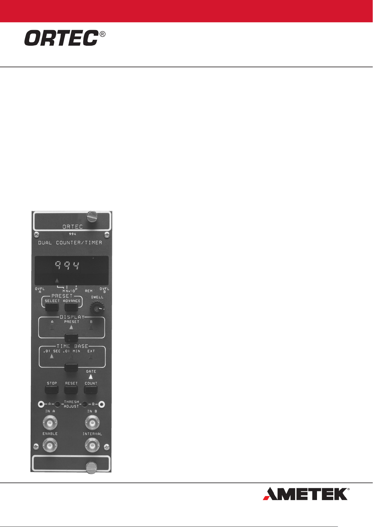
994
Dual Counter and Timer
•Two 8-decade counters and a timer with the
configuration flexibility to serve a variety of
measurement needs
•RS-232-C option provides CCNIM capability
with full computer control and readout
•Can directly drive printers having RS-232-C
ports
•An 8-decade LED display provides
instantaneous readout of the entire counter
capacity, even in dimly lighted rooms
•All commonly used controls are easily
accessible on the front panel
•100-MHz counting rate capability
•Preset time or counts set with the precision
of a two-digit and decade selection
•All options are field-installable
The ORTEC Model 994 Dual Counter and Timer
incorporates two eight-decade counters and a
blind preset timer. Considerable functional
flexibility is designed into the instrument,
allowing it to be configured for a variety of
easurement tasks. Typically, it can be used as
m
two counters recording separate events under
the control of the preset blind timer. When
continuous readout of the time is needed,
ounter A can be diverted to count the time
C
while Counter B records external events. This
provides the function of a counter and a
displayed preset timer. In some applications, the
time taken to count a preset number of events
must be measured. For this application, Counter
A, coupled with the preset blind counter, can be
used as a preset counter while Counter B
records the time in 0.01-second intervals. In
measurements where it is important to correct
for the dead time of the detector and its
associated electronics, the Gate A input can be
switched to also gate the time clock On and Off
with a 100-ns time resolution. A positive logic
signal that defines the system live time is
connected to the Gate A input. This configuration
provides a live-time clock (Counter A) and a
counter (B).
Excellent flexibility in setting the preset value is
offered by the MN X 10
values provide two-digit precision, while P
selects the decade. Presets can be chosen in
the ranges of 0.01 to 990,000 seconds, 0.01 to
990,000 minutes, or 1 to 99,000,000 counts.
The basic Model 994 includes an 8-decade LED
display that offers instantaneous visual readout
of the full contents of Counter A or B, even in a
dimly lighted room. By adding field-installable
options, considerably enhanced readout and
control capabilities can be incorporated.
The full power of CCNIM (Computer-Controlled
NIM) can be obtained by adding the RS-232-C
option. This plug-in board allows computer
control of all functions normally selectable from
the front panel, including start and stop count,
readout, reset, setting the preset value, selecting
the displayed counter, and selecting the desired
time base. To eliminate accidental operator
interference, the computer can disable all frontpanel controls in the Remote mode. Computer
readout with the CCNIM option includes A and B
counts, the preset value, and which counter is
being displayed. The CCNIM option can directly
drive printers having RS-232-C ports.
The inputs to Counters A and B are individually
selectable as either positive or negative sensing
inputs by changing the Input Polarity Jumpers on
the counter printed wiring board (PWB). The
P
selection. The M and N
negative input mode is designed to accept NIMstandard, fast-negative logic pulses with a fixed
threshold of –250 mV on a 50- input
impedance. The negative inputs can handle
counting rates up to 100 MHz. The positive input
ode can accept counting rates up to 25 MHz
m
on a 1000- input impedance. To enhance the
flexibility of the positive input mode, precision
discriminators are included on both counters.
he discriminator thresholds are variable over
T
the range from +100 mV to +9.5 V using frontpanel, 25-turn trimpots. The thresholds can be
adjusted to suit the amplitude of a specific
source of logic pulses or used as precision
integral discriminators on analog pulses. For the
latter application, the TTL logic outputs of the
discriminators are provided as test points on the
front panel. These outputs can be used to trigger
an oscilloscope while viewing the analog signal
at the counter input on the oscilloscope. The
oscilloscope trace will show the signals that are
being counted by the Model 994, thus permitting
a very selective adjustment of the threshold.
All the commonly used functions are
conveniently accessible on the front panel.
Manual control of the Count, Stop, and Reset
functions is via three push-buttons. The Gate
LED is illuminated when the Model 994 is
enabled to count. Selection of the 0.01 second,
0.01 minute, or external time base is made by
the Time Base push-button. In the external
mode, the preset counter counts the events at
the counter A input. The Display push-button
switches the display to show the contents of
Counter A, the preset stop value, or the contents
of Counter B. To change the preset value, the
Preset mode must first be selected with the
Display push-button. Subsequently, the Preset
Select push-button is used to choose M, N, or P
for adjustment. Changing the value of M, N, or P
is accomplished with the Preset Advance pushbutton. The display contains LED flags to
indicate whether M, N, or P has been selected,
to warn when overflows have occurred in
Counter A or Counter B, and to advise when the
front-panel controls are disabled by the computer
in the Remote mode. When the Model 994 is
used in the automatic recycle mode, the Dwell
knob adjusts the dwell time of the display from 1
to 10 seconds.
The counting function of the entire module can
be disabled by holding the Enable input below
+1.5 V using an external signal source. This
condition also turns Off the Gate LED. Open
circuit or >+3 V at the Enable input allows the
instrument to count, if the Count mode has been
activated. The Interval output of another ORTEC
994
Dual Counter and Timer
timer can perform this function to synchronize
the Model 994 counting with the other timer. The
Interval outputs on all ORTEC timers provide
nominally +5 V when counting and <+0.5 V
when counting is inhibited.
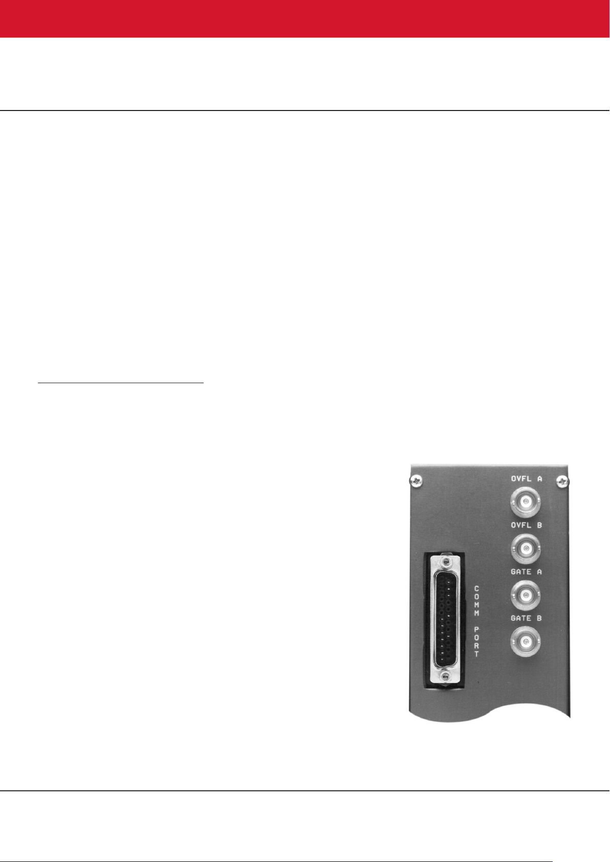
Independent gating of the A and B Counter
inputs can be achieved with the Gate A and Gate
B inputs on the rear panel. The interface
connector for the RS-232-C option is located on
the rear panel. Each counter has a rear-panel
output dedicated to signaling overflows.
Counting these overflows on another counter
extends the counting capacity of the Model 994.
The Model 994 derives its power from the ±12 V
and +6 V supplies in a standard NIM bin with
power supply. For bins that do not contain a
+6 V supply, an Internal +6 V Supply option is
available. This option is field-installable and
derives its power from the 117 V ac lines in the
bin.
Specifications
PERFORMANCE
COUNT CAPACITY 8 decades for counts ranging
from 0 to 99,999,999 in each of 2 counters.
MAXIMUM COUNTING RATE 100 MHz for negative
inputs, 25 MHz for positive inputs.
TIME BASE 10-MHz clock with minimum preset or
displayed intervals of 0.01 seconds or 0.01 minutes.
Synchronizing error is nominally 100 ns. Also accepts
an external input from the Counter A input (In A) when
the Ext (External) mode is selected.
TIME BASE INACCURACY ±0.0025% over the 0 to
50°C operating temperature range.
PRESET TIME/COUNTS The module stops counting
when the preset value MN X 10
blind preset register. M and N are digits ranging from 0
to 6. With the 0.01-second time base, preset times
from 0.01 to 990,000 seconds can be used. Preset
times from 0.01 to 990,000 minutes are available using
the 0.01-minute time base. In the Ext time base mode
preset counts in the range of 1 to 99,000,000 can be
used.
POSITIVE INPUT DISCRIMINATOR Threshold
variable from +100 mV to +9.5 V with a 25-turn trimpot.
PULSE PAIR RESOLUTION <10 ns for negative
inputs; <40 ns for positive inputs.
INDICATORS
COUNTER DISPLAY 8-digit, 7-segment LED display
with leading zero suppression. When displaying time,
2 digits to the right of a decimal point are included.
OVERFLOW INDICATORS LED indicators labeled
OVFL A and OVFL B illuminate when the
corresponding A or B Counter exceeds its capacity of 8
decades. The indicator remains on until a reset is
generated.
P
is reached on the
M, N, AND P INDICATORS 3 LED indicators aid in
the selection of the preset value. When the Preset
display function is activated, the Select push-button
selects which of the 3 LEDs is illuminated. When one
of these LEDs is On, that digit of the preset value can
be incremented using the Advance push-button.
DISPLAY 3 LEDs labeled A, B, and Preset indicate
the information being displayed in the counter display.
Counter A, Counter B, or the Preset value may be
displayed by repeatedly pressing the Display pushbutton until the desired LED is illuminated.
TIME BASE 3 LEDs indicate the selected time base
source. By repeatedly pressing the Time Base pushbutton, 0.01 Sec, 0.01 Min, or the Ext mode can be
chosen.
GATE A single LED indicates that the entire
instrument is enabled to count. For the Gate LED to be
illuminated, the module must be placed in the Count
mode (either manually or via the interface option), the
Enable input must be above +3 V, and the preset stop
condition must not have been reached.
REMOTE A single LED labeled REM indicates that the
Model 994 is under computer control, and all frontpanel controls are disabled. This mode is set by the
ENABLE_REMOTE command.
CONTROLS
DISPLAY Push-button selects the contents of Counter
A or B, or the Preset value for presentation in the
8-decade display. Repeatedly pushing the button
cycles the selection through the three choices as
indicated by the A, B, and Preset LEDs.
SELECT Push-button chooses the M, N, or P digit in
the display of the preset value. Pushing the button
advances the selection through the three choices as
indicated by the illuminated LED. The Select pushbutton operates only if the Preset mode has been
selected by the Display push button.
ADVANCE Push-button increments the preset digit
selected by the Select push-button once each time the
Advance button is depressed. The M and N digit
ranges are both 0 to 9. The P digit range is from 0 to 6.
The Advance push-button operates only if the Preset
mode has been selected by the Display push-button.
TIME BASE Each push on this button advances the
selection one step through the three time base choices
of 0.01 Sec, 0.01 Min, and Ext to determine the time
base source for the preset register.
STOP This push-button stops all sections of the
instrument from counting.
RESET Depressing this button resets both counters to
zero counts and turns Off both overflow indicators. It
also clears any counts accumulated in the blind preset
counter, but does not change the selected preset
value. When power is turned On to the Module, a
Reset is automatically generated.
COUNT Pushing this button enables the counting
condition for the entire instrument, providing the
Enable input is not held below +1.5 V and the preset
value has not been reached.
THRESH ADJUST (A and B) Front-panel mounted,
25-turn trimpots to adjust the positive input thresholds
for Counters A and B. The range is from +100 mV to
+9.5 V. Adjacent test points provide the TTL logic
signal outputs from the discriminators to facilitate
adjustment using an oscilloscope.
DWELL A one-turn potentiometer on the front panel
with an On/Off switch at the fully counterclockwise
position. Adjusts the display dwell time over the
nominal range from 1 to 10 seconds. When the
instrument is in the Recycle mode, dwell time occurs
after the preset value has been reached. Turning the
switch Off at the fully counterclockwise position selects
the Single Cycle mode. If the print loop option is used,
the Dwell control is disabled when the print loop
controller is active and controlling the dwell time.
INPUT POLARITY JUMPERS Two jumpers located
on the printed wiring board (PWB) separately select
the desired input polarities for inputs In A and In B. P =
positive, N = negative.
A COUNTER/TIMER JUMPER Two-position jumper
located on the PWB. In the Counter position, Counter
A always counts and displays the events connected to
In A. When set to the Timer position, Counter A counts
and displays the time if either the 0.01-Sec or the
0.01-Min time base is selected. If the Ext time base is
selected, Counter A will count and display the events
from In A.
2

994
Dual Counter and Timer
B COUNTER/TIMER JUMPER Two-position jumper
located on the PWB. In the Counter position, Counter
B always counts and displays the events from In B. In
the Timer position with the Ext time base selected,
Counter B counts and displays the time in 0.01-second
intervals. With either a 0.01-Sec or 0.01-Min time base
selected, Counter B counts and displays the events
from In B.
GATE A (LIVE TIME/NORMAL) JUMPER Two-position
jumper mounted on the PWB. In the Normal position,
the signals from the rear-panel Gate A connector gate
the events from the In A connector. In the Live Time
position, the signals from the Gate A connector gate
the 10-MHz clock to form a live-time clock.
1 CYCLE/RECYCLE Selection of either the 1 Cycle or
the Recycle mode can be made via an 8-pin DIP
switch on the RS-232-C interface board. The Recycle
mode can be used when the computer is able to
respond with a data transfer when the Model 994
reaches the preset value. Upon reaching preset, the
Model 994 latches its data into a buffer, resets the
counters, and starts the next counting interval. This
process takes ~50 µs. The computer reads the data in
the buffer before the next counting interval ends. In the
1 Cycle mode, the Model 994 simply stops counting
and waits for further commands when the preset value
is reached.
INPUTS
IN A Use of this input is affected by the A
Counter/Timer Jumper.
Positive Input Front-panel BNC connector for
Counter A accepts positive unipolar signals; minimum
width above threshold, 20 ns at a 50% duty cycle. The
threshold is adjustable from +100 mV to +9.5 V via a
front-panel 25-turn trimpot. Z
dc-coupled.
Negative Input Changing the Input Polarity Jumper
position on the counter board permits selection of the
NIM-standard fast-negative logic input which is
designed to accept –600 to –1800 mV pulses with a
fixed discriminator threshold of –250 mV. Z
dc-coupled. Minimum pulse width above threshold is
4 ns.
IN B Identical to In A except that it feeds Counter B.
Use of this input is affected by the B Counter/Timer
Jumper.
ENABLE Front-panel BNC input connector accepts
NIM-standard, slow-positive logic pulses to control the
counting condition of the entire module. A level of
>+3 V or open circuit allows counting provided the
instrument is in the Count mode and has not reached
the preset value; <+1.5 V inhibits counting. The driving
source must be capable of sinking 5 mA of positive
current during inhibit; input protected to +25 V.
= 1000 to ground;
in
in
= 50 ;
GATE A Rear-panel BNC input connector is identical
to the Gate B input with the following exception. With
the Gate A jumper on the PWB set to the Normal
position, the Gate A input controls counting of the In A
events in Counter A. By moving the PWB Gate A
jumper to the Live Time position, the Gate A input also
controls the 10-MHz clock to form a live-time clock with
a 100-ns resolution. A level >+3 V or an open circuit
allows counting of the clock. A level <+1.5 V is used to
inhibit counting of the clock during dead-time intervals.
GATE B Rear-panel BNC connector accepts NIMstandard, slow-positive logic signals to control the
counting in Counter B. A level >+3 V or open circuit
allows counting; <+1.5 V inhibits counting; input
protected to +25 V. The driving source must be
capable of sinking 5 mA of positive current during
inhibit.
OUTPUTS
INTERVAL Front-panel output BNC connector
furnishes a positive level during the counting interval.
The level is nominally +5 V when counting is enabled
and <+0.5 V when counting is disabled. Z
OVFL A Rear-panel output BNC connector provides a
NIM-standard, slow-positive logic signal each time
Counter A overflows its 8-decade capacity. The signal
has a nominal amplitude of +5 V; width ~20 µs.
OVFL B Rear-panel output identical to OVFLA except it
monitors overflows from Counter B.
~30 .
o
INTERFACE
SERIAL When the RS-232-C option board is plugged
in, it furnishes a rear-panel, 25-pin, male, D connector
containing all signals for standard RS-232-C
communications. It also contains connections for
20-mA current loop communications. The fieldinstallable RS-232-C option provides computer control
of the following functions: Count, Stop, Reset, Remote,
setting the preset value, selecting the displayed
counter, and selecting the desired time base. In the
Remote mode, the computer can disable all front-panel
controls. Computer readout includes: A and B counts,
the preset value, and which counter is being displayed.
3

ELECTRICAL AND MECHANICAL
POWER REQUIRED The basic Model 994 derives its power from a NIM bin furnishing ±12 V and +6 V. For NIM bins
that do not provide +6 V, an optional Internal +6 V Supply is available. This option is field-installable and draws its power
from the 117 V ac lines in the bin. With the Internal +6 V Supply installed, the power requirements are shown in column
4 and not required in column 3.
I
Bin Supplied +6 V Supply
+12 V –12 V +6 V 117 V ac
Basic Model 994 35 mA 115 mA 1300 mA 110 mA
Model 994 plus RS-232-C option 54 mA 130 mA 1800 mA 145 mA
WEIGHT
Net 2.4 kg (5.2 lb).
Shipping 3.7 kg (8.2 lb).
DIMENSIONS NIM-standard double-width module, 6.90 X 22.13 cm (2.70 X 8.714 in.) front panel per DOE/ER-0457T.
nternal
Ordering Information
odel Description
M
994 Basic module without plug-in options.
99X-1 RS-232-C Interface option (cable not included).
99X-4 Internal +6 V Supply option.
C-75 Female-to-female RS-232-C null modem cable (3-meter length).
C-80 Male-to-female RS-232-C extension cable (3-meter length).
994
Dual Counter and Timer
Specifications subject to change
010421
 Loading...