

ORTE Pellet Comfort, Pellet Comfort 7, Pellet Comfort 10, Pellet Comfort 16, Pellet Comfort 25 Maintenance Manual
www.orte.pl
Page | 1
Pellet Comfort water boiler with nominal heat capacity of: 7, 10, 16 and 25 kW
with automatic solid fuel feeding, using pellet.
TECHNICAL AND MAINTENANCE DOCUMENTATION
OPERATION AND MAINTENANCE MANUAL
WARRANTY
device version: 04/2017
document version: 13/2018/JK
Orte Polska Sp. z o.o.
Słoneczna 1,
96-321 Oddział
Manufactured in Poland
www.orte.pl

www.orte.pl
Page | 2
I. OPERATION AND MAINTENANCE MANUAL
1. General information ………………………………………..……………………………………………………………………………….………3
2. Technical specification…………………………………………………………………………………………………………………………..…………..4
3. Intended use and characteristics……………………………………………………………………..……………………………………...6
3.1 Intended use……………………………………………………..…………………………………………………………………………………….…6
3.2 Information about the boiler……………………………………………………………..……………………………………………..…..……6
3.3 Installation guide………………………………………………………………………………………………..…..……………………………..…..6
3.4 Operation guide…………………………….…..………...……………………………………………………………………………………….…..7
3.5 Safety systems………………………………………………………………………………………………………..…..……………………………..7
3.6 Boiler construction……………………………………………………………………………………………………………………………..........8
3.6.1. Boiler diagram…………………………………………………………………………………………………………………………………..8
3.6.2. Installation/disassembly diagram of the bin/tray…………………………………………………………………………….10
3.6.3.Burner diagram………………………………………………………………………………………………………………..................11
3.7 Operation and storage conditions…………………………………………………………………………………………………………….11
3.8 Minimal distances and flammability………………………………………………………………………………………………………….12
3.9 Minimal reflux temperature……………………………………………………………………………………………………………………..12
3.10 Tools, materials and auxiliary measures…………………………………………………………………………..……...................12
4. Safety……………………………………………………………………………………………………………………..……….………………………………12
4.1 Safety tips…………………………………………….…………………………………………………..……………………………………………….13
5. Transport and installation……………………………………………………………………………………………………………………..…..…….15
5.1 Transport………………………………………………………………………………………………………………………………..………………..15
5.2 Installation………………………………………………………………………………………………………………………………….…………….16
5.3 Installation conditions…………………………………………………………........................................................................16
5.4 Distance from the walls……………………………………………………………………………………………………………..……..........17
5.5 Distance from flammable materials……………………………………………………………………..…………………………………..17
5.6 Exhaust connection guide……………………………………………………………………………..………………………………………….17
5.6.1.Exhaust connection…………………………………………………………………………..……………………………………………..18
5.6.2. Inlet air connection…………………………………………………..…………………………………………………………………….19
5.7 Hydraulic connections…………………………………………………………………………………………………………………………………………….19
5.7.1.Connection of the boiler to CO system………………………………………………………………………………………………………………19
5.8. Filling the heating system and checking for leaks………………………………………..………………………………………………………….21
6. Starting up……………………………………………………………………………………………………………………………………………………….22
6.1 Before start up……………………………………………………………………………………………………………………………………….…22
6.2 First start up……………………………………………………………………………………………………………………………………………..23
7. Operation……………………………....………………………………………………………………………………………………………………….…...24
7.1 Turning on the device…………………………………………………………………………………………………………….…………………24
7.2 Safe turn off………………………………………………………………………………………………………………………………………………25
7.3 Fuel …………………..………………………………………………………………………………………………………………………………….….25
7.4 Suggested settings…………………………………………………………………………………………………………………………………...25
7.5 Messages on the controller…………………………………………………………………………………………………..…………….……26
7.6 Burner trouble………………………………………………………………………………………………………………………………………....27
7.7 Replacing spare parts…………………………………………………………………………………………………..……………………………28
7.7.1. Lighter replacement………………………………………………………………………………………………………………………..28
7.7.2. Photoelement replacement…………………………………………………………………………………………………………….28
8. Maintenance…………………..……………………………………………………………………………………………………………....................28
8.1 Cleaning the boiler……………………………………………………………………………………………………………....…..……………..28
8.2 Cleaning the burner…………………………………………………………………………………………………………….…….……………..29
8.3 Cleaning the heating system…………………………………………………………………………………………..………………………..30
9. Shut-down………………….…………………………………………………………………………………………………..….……………………………31
10. Wiring diagram of the boiler………………………………………………………………………………………………………….………………..31
11. Warranty terms…………………………………………………………………….………………………………………………………………………...32
12. Warranty card and protocols…………………………………….…………………......................................................................33
13. EC declaration of conformity ...............................................................................................................................39
II. TEMPERATURE CONTROLLER RK-2006 SPGM OPERATING INSTRUCTION
www.orte.pl

www.orte.pl
Page | 3
A filled Installation Protocol must be sent (scan, xerox) to the Manufacturer within 14 days from the start-up
of the device. OTHERWISE, THE WARRANTY IS INVALID.
Operation and maintenance manual
Before installation and operation of the Pellet Comfort boiler (hereinafter referred to as
the device or boiler), read and strictly adhere to this manual and read the terms of your warranty.
REMEMBER!!! IF YOU WANT TO TURN OFF THE DEVICE – USE THE STOP BUTTON ON THE CONTROL
PANEL. DO NOT UNPLUG THE DEVICE BECAUSE OF THE RISK OF EXPLOSION!
National and local provisions regarding installation and operation must be complied with.
1. GENERAL INFORMATION
Boilers comply with the requirements of class 5 according to PN EN 303-5:2012.
This Technical and Maintenance Documentation is an integral part of the device and must be delivered to
the user together with the machine.
Electric connections must be performed by an electrician with appropriate permissions. Electric installation
must be designed and performed by persons with appropriated permissions and additionally secured with
a differential switch (residual current 30mA).
Before connecting the device, a chimney sweeper with appropriate permissions must perform an
acceptance test.
Connection and commissioning of the boiler must be performed by an authorized installer with
appropriate permissions, designated by the Seller.
The manufacturer reserves the right to make technological changes, amend technical data, dimensions,
appearance, equipment, without prior notification, if the differences are not significant and do not affect
the operation of the device.
Orte Polska Sp. z o.o. is not liable for damages resulting from improper installation of the boiler,
unauthorized modifications, using spare parts not authorized by the manufacturer, or failure to comply
with the terms and conditions included in the Technical and Maintenance Documentation (hereinafter:
TMD).
www.orte.pl
www.orte.pl
Page | 4
TYPE with RK 2006-SPGM controller
PELLET
COMFORT 7
PELLET
COMFORT 10
PELLET
COMFORT 16
PELLET
COMFORT 25
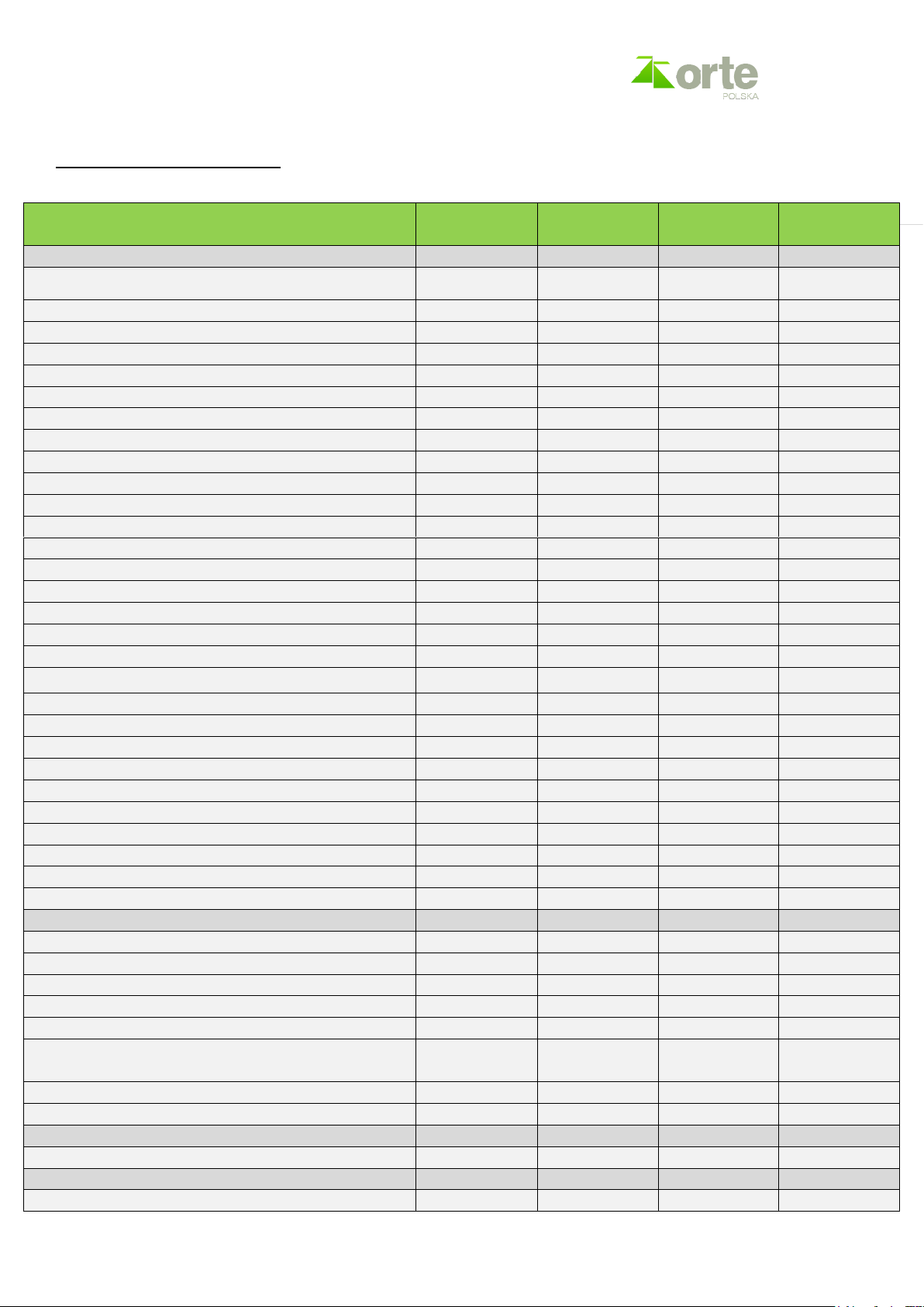
TECHNICAL DATA
Area of a house built according to the current energy
standards (m2)
120
150
240
350
Max. power supplied with fuel (kW)
8.3
12
18
26.6
Nominal power
7.3
10.3
16
23.6
Partial power
Not applicable
Not applicable
Not applicable
7.3
Dust emission class according to EN 303-5:2012
5 5 5
5
CO emissions class according to PN EN 303-5:2012
5 5 5
5
OGC emission class according to PN EN 303-5:2012
5 5 5
5
Efficiency class
5 5 5
5
Efficiency for max. power (%)
88.1
88.1
88.4
88.7
Efficiency for min. power (%)
Not applicable
Not applicable
Not applicable
87.2
Power supply (V)
230
230
230
230
Power consumption at stand-by (W)
2.7
2.7
2.7
2.7
Power consumption at rated power (W)
90
90
90
90
Power consumption at partial power (W)
Not applicable
Not applicable
Not applicable
90
Water capacity of the boiler (litres)
59
59
94
94
Max. operating temperature (boiler output) (°C)
80
80
80
80
Max. operating pressure (bar)
1.5
1.5
1.5
1.5
Safety heat exchanger
o o o
o
Fuel consumption at rated power (kg/h)
1.74
2.45
3.8
5.58
Exhaust temperature at max. power (°C)
82
100
107
115
Exhaust temperature at min. power (°C)
Not applicable
Not applicable
Not applicable
75
Exhaust stream at max. power (g/s)
18
19
17.5
16.23
Exhaust stream at min. power (g/s)
Not applicable
Not applicable
Not applicable
7.55
Safety temperature limit (°C)
80
80
80
80
Stack effect at max. power (Pa)
20
20
25
25
Required protection (A)
5 5 5
5
Frequency (Hz)
50
50
50
50
Safety systems
6 6 6
6
Min. amount of air required for proper fuel combustion (m3)
80
100
150
150
BOILER DIMENSIONS
Height (mm)
1095
1095
1216
1216
Width of the boiler (mm)
390
390
490
490
Width of the boiler together with the tray (mm)
970
970
1141
1141
Depth with the burner (mm)
1400
1400
1500
1500
Weight (kg)
360
360
520
520
Water outlet/return tube (threaded)
G1 ½ external
thread
G1 ½ external
thread
G1 ½ external
thread
G1 ½ external
thread
Exhaust pipe outlet (mm)
159
159
159
159
Chimney cross-section (cm x cm)
14 x14
14 x14
20 x14
20 x14
TYPE OF FUEL
A1 class pellet according to EN ISO 17225-2:2014
s s s
s
TANK
Standard – near the boiler (kg)
100
100
150
150
2. TECHNICAL SPECIFICATION
www.orte.pl

www.orte.pl
Page | 5
TYPE with RK-2006 SPGM controller
PELLET
COMFORT 7
PELLET
COMFORT 10
PELLET
COMFORT 16
PELLET
COMFORT 25
Custom: 270, 380l, 560l.
o o o
o
External feeding
o o o
o
Fuel feeding from the tank to the burner
s s s
s
BURNER
Steel grade:1.4828
s s s
s
Cylindrical burner
s s s
s
Furnace made of chrome heat-resistant steel
s s s
s
Top-loading burner
s s s
s
Automatic ash push-out
s s s
s
Heating-burning element
s s s
s
Jet fan
s s s
s
Motoreducer x 2
s s s
s
Photocell – optical flame control sensor
s s s
s
Pellet burning grill
s s s
s
RK 2006 SPGM CONTROLLER
MEASURING INPUTS
Boiler temperature sensor
s s s
s
Return temperature sensor
s s s
s
CO temperature sensor behind the valve
s s s
s
External temperature sensor
s s s
s
Feeder temperature sensor
s s s
s
Photodetector
s s s
s
Room thermostat
s s s
s
CO circuit room thermostat with valve
s s s
s
CONTROL OUTPUTS
Fan
s s s
s
CO pump
s s s
s
CO2 pump behind the valve
s s s
s
SWU pump or return pump
s s s
s
Mixing valve
s s s
s
Lighter
s s s
s
External feeder (STOKER)
s s s
s
External feeder
s s s
s
Cleaning mechanism
s s s
s
Fan
s s s
s
FUNCTIONS
Memory: 4 types of fuel-pellet. 1)
s s s
s
Possibility of using wood
s s s
s
Support for two CO circuits
s s s
s
Weather-related control
s s s
s
Data transmission 2)
s s s
s
On-line control 3)
s s s
s
1) Ability to set burning parameters for four types of pellet. Changes in the operation of the fan, feeder and lighter are stored for the
currently selected type of fuel.
2) An additional room thermostat with RT-208GT data transmission is required. Ability to control and set all boiler parameters on
the room thermostat.
3) An additional Internet module UMI-1 WI-FI or LAN is required.
The manufacturer reserves the right to make technical changes at any time.
www.orte.pl

www.orte.pl
Page | 6
3. INTENDED USE AND CHARACTERISTICS
3.1. Intended use
Water boilers Pellet Comfort are delivered as integrated heating devices that consist of a boiler with a
capacity of 7.3 or 23.6 kW along with a burner, pellet tray and feeder. The devices are designed for heating
in buildings where there is a central heating water installation (C.O.) and/or a usable water installation
(CWU). 7-16 kW boilers are adapted to work in an open system, which means, among others, that the
hydraulic system must have an open expansion vessel with an overflow pipe and be carried out in
accordance with the applicable standards for open systems or adapted to work in the system with closed
buffer.
There are Pellet Comfort boilers where the flow of heated water depends on the type of water system and
water pumps used. The boilers are designed for use with cubic capacity of up to 700 m3.
In standard, the kit includes:
- Technical and Maintenance Documentation along with the warranty,
- Technical and Maintenance Documentation of the controller,
- rake,
- pellet tray
3.2. Information about the boiler
This manual contains important information regarding safe installation, commissioning and maintenance of
the boiler.
The boiler should be installed by a qualified installer.
In order to ensure intended use, you must adhere to the manual, information on the nameplate and
technical data. It is forbidden to install the boiler in apartments and corridors. Boilers can be installed in
accordance with local and national regulations and in accordance with safety rules described in the section
“Safety”.
Installation and use of the boiler are allowed only in rooms with constant and proper ventilation. The
boiler may be used to heat water and for indirect preparation of usable warm water.
The boiler must work at the minimum return temperature of 42÷60˚C. One must ensure this limit
temperature by using appropriate devices, e.g. thermostatic mixing valve.
3.3. Installation guide
INFO One must adhere to regulations and national standards during installation and operation.
During installation of the heating system, one must adhere to the following regulations:
• local building regulations concerning the conditions of installation
• local building regulations concerning air supply for combustion and exhaust discharge.
• regulations and standards concerning equipping the heating system with automation safety devices.
www.orte.pl

www.orte.pl
Page | 7
3.4. Operation guide
When using the heating system, adhere to the following tips:
The boiler should be working at the minimal return temperature from 42 ° C to 60 °C. Do not
exceed 80°C at the system supply.
Ensure this limit temperature by using appropriate device or its settings.
The boiler can only be operated by adults familiar with its use.
Ensure that children do not remain unattended near the working boiler.
Do not add any liquids or water to increase the power of the boiler.
Ash should be placed in a non-combustible container with a lid.
Do not place on the boiler or in its vicinity (within safe minimum distance) flammable objects or
substances (e.g. kerosene, oil).
To clean the boiler, use only gentle cleaning agents.
Do not use the boiler without the recommended operating pressure.
During the boiler operation, do not open the doors of the combustion chamber.
Comply with the operating manual.
The installer must provide the user with information about the operation and proper use of the
boiler.
Do not use the boiler in case of danger of explosion, fire, leaks of combustible gases or vapours (e.g.
when gluing linoleum, PVC etc.).
Pay attention to the flammability of construction materials.
3.5. Safety systems
Each boiler is equipped with 6 interdependent safety systems.
1. Feeder temperature sensor Installed during the commissioning in a smaller tube between the burner
and the flexible pipe connected to the feeder. The sensor informs about the backflow of fire to the tray
and an increase of the feeder temperature above 45°C.
2. Elastic tube between the metal pipe of the burner and the feeder. If the temperature sensor of the
feeder is damaged or improperly installed, the fire that goes back to the feeder dissolves the elastic pipe
within 2-3 seconds, cutting of the fire from the feeder where pellet is stored. Additionally, the elastic pipe
is not placed directly over the burner, but on the side.
3. Boiler overheating sensor. If the water temperature exceeds 80°C, the burner automatically goes into
putting-out mode. This prevents the burner from working in the case of a limited heat perception.
4. Photoelement defines the quality of the combustion process. If there is not enough air in the furnace,
the fire’s brightness drops below the pre-set level. The burner automatically goes from the maximum
power mode (feeding large amount of fuel) to the firing up mode (small amount of fuel). If the situation
does not change, the fire’s brightness remains at the level not exceeding the required brightness. The
burner will display “no fuel” error and will stop fuel supply, which will prevent excessive carbon monoxide
emission.
5. STB with manual lock deletion.
6. The controller has a password on service parameters.
www.orte.pl
www.orte.pl
Page | 8
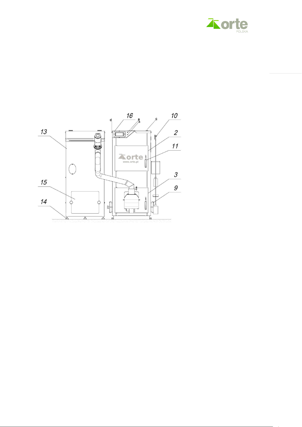
3.6. Construction of the boiler
Pellet Comfort boiler consists of the following assemblies: heat exchanger, automation/controller, burner
along with a feeder, electrics, wiring and a tray. The controller is installed in the upper part of the boiler
cover. Near the controller, there are fuses 5A (a) and 2.5A (b) a central switch is on the top plate of the
boiler (c). STP is near the controller, on the left side of the boiler (d). The feeder is made of high-quality
powder-coated sheet metal. The combustion chamber is lined with ceramic tiles.
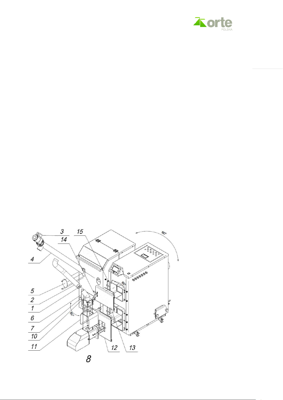
3.6.1. Boiler diagram
www.orte.pl
www.orte.pl
Page | 9
www.orte.pl
www.orte.pl
Page | 10
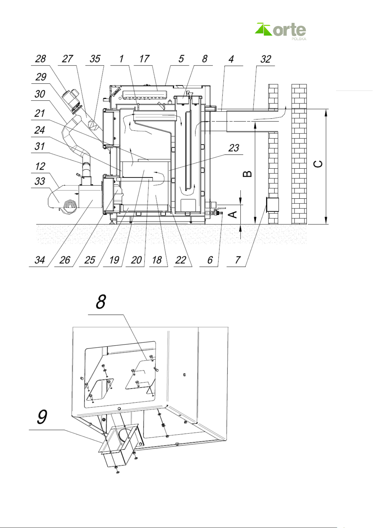
1 – steel body; 19 – side ceramic tile II;
2 – upper door; 20 – upper ceramic tile I;
3 – lower door; 21 – upper ceramic tile II;
4 – flue; 22 – back ceramic tile I;
5 – external jacket; 23 – back ceramic tile II;
6 – water drain pipe; 24 – front ceramic tile;
7 – chimney chamber cleaning hole; 25 – drawer;
8 – upper cleaning hole; 26 – ceramic cover of the burner;
9 – lower cleaning hole; 27 – external feeder;
10 – hardware; 28 – feeder drive assembly;
11 – clamp; 29 – bearing assembly;
12 – burner; 30 – feeder flexible pipe;
13 – charging hopper; 31 – band clip;
14 – adjustment foot; 32 – boiler attachment;
15 – bin cleaning hole; 33 – burner back cover;
16 – controller; 34 – burner upper cover;
17 – controller run-time module; 35 – feeder snail;
18 – side ceramic tile I;
3.6.2.
Diagram presenting the disassembly of the bin and the feeding system on the opposite side of the boiler.
www.orte.pl
www.orte.pl
Page | 11
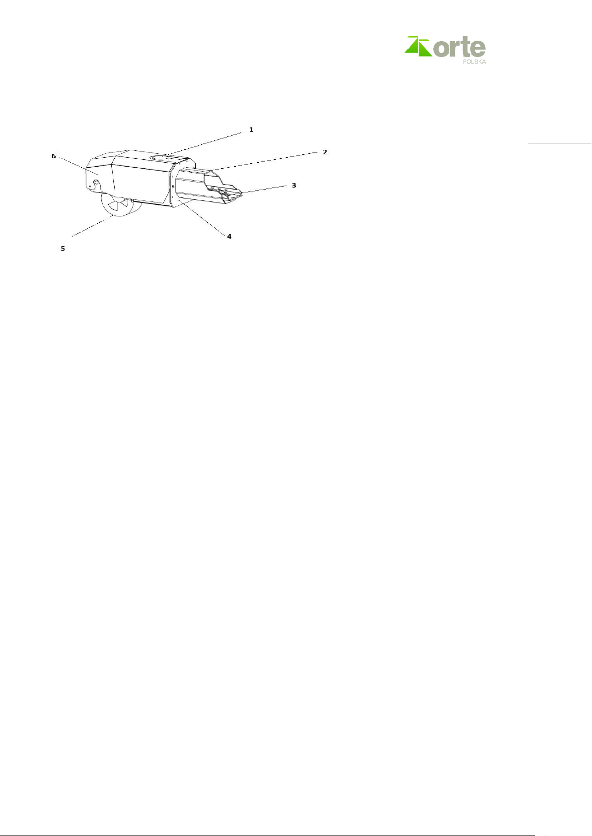
3.6.3. Diagram of the burner
1 - fireplace inlet 4 - burner front panel
2 - burner pipe 5 - fan cover
3 - burner grill 6 - burner upper and back cover
3.7. Operation and storage conditions
Before installation, read the requirements of this manual and the requirements of national and local laws.
The installation design should be performed by a contractor with appropriate permissions which, in
consultation with a chimney sweeper specialist and fire-fighting specialist, will issue a written opinion on
the condition of installation and operation of the device, in particular on the insulation, floor bearing
capacity, ventilation and gas exhaust installation.
During installation, take into consideration the requirements of applicable regulations. In case of doubt,
consult a fire protection expert.
The room where the heating device is placed must have insulation, floor bearing capacity and ventilation in
accordance with appropriate provisions, and must be connected to an individual exhaust pipe/chimney.
Storage conditions:
• temperature between -10°C and 50°C
• humidity between 5% and 70%
• atmospheric pressure between 800hPa and 1200hPa
• good ventilation – meeting the required standards (supply air at least as
extract air)
• low dust level and lack of chemical pollution
• room free of flammable materials
If the boiler is stored longer than 2 years from the date of manufacture, it should be started in the
premises of the manufacturer in order to verify proper operation.
www.orte.pl

www.orte.pl
Page | 12
3.8. Minimal distances and flammability of construction materials
INFO: Depending on the country, different minimum distances may apply – please consult an installer or
a chimney-sweeper.
No flammable materials allowed in the room.
3.9. Minimal reflux temperature
The boiler must operate with a minimum reflux temperature of 42 ÷ 60 ° C.
Ensure the limit temperature by using appropriate device (mixing valve with pump).
3.10. Tools, materials and auxiliary measures
Installation and maintenance of the boiler require standard tools used by installers of heating and water
systems.
Cleaning tools are delivered along with the boiler.
4. SAFETY
The device must be installed and accepted only by an authorized installer with confirmed qualifications.
The boiler must be installed, placed and used in accordance with applicable regulations. Strictly adhere to
the instructions contained in Technical and Maintenance Documentation. Do not install the boiler in places
at risk of fire, explosion, flooding or freezing. The boiler must be connected to an electrical outlet –
grounded and with a differential protection. The boiler is adapted to an open system, which means that
the hydraulic system must have an open expansion vessel with an overflow pipe.
Unattended minors and pets cannot be near the operating boiler.
Do not exceed maximum power. Ensure proper air circulation – in accordance with appropriate
regulations. Ensure chimney-sweep inspection in accordance with applicable regulations, not less
frequently than once every 3 months or in accordance with local regulations.
Ventilation of the room where the boiler is placed must be made in accordance with applicable
regulations.
In order to operate properly, the boiler needs fresh air and the required chimney draft.
Air should be supplied to the burner in order to carry out proper combustion processes in the boiler
chamber.
Do not connect several heating devices to the same chimney. However, if there are other heating devices
installed in the room (connected to other chimneys), supply sufficient amount of air to ensure combustion
in each device and ensure sufficient air for room ventilation, taking into account all the devices.
It is forbidden to open the device during operation due to the risk of burns.
No flammable materials allowed in the room.
Fuel storage – in accordance with relevant regulations and standards (in a different room than the boiler).
An ABC type powder extinguisher must be placed near the device.
In the event of a chimney fire, immediately put out the burner by pressing the central switch – position 0,
placed above the controller. Do not open the ash pan, cut off all access of air needed for combustion. Do
www.orte.pl
 Loading...