

Ortal Wilderness Traditional 36, Wilderness Traditional 42 Fireplace Installation Manual
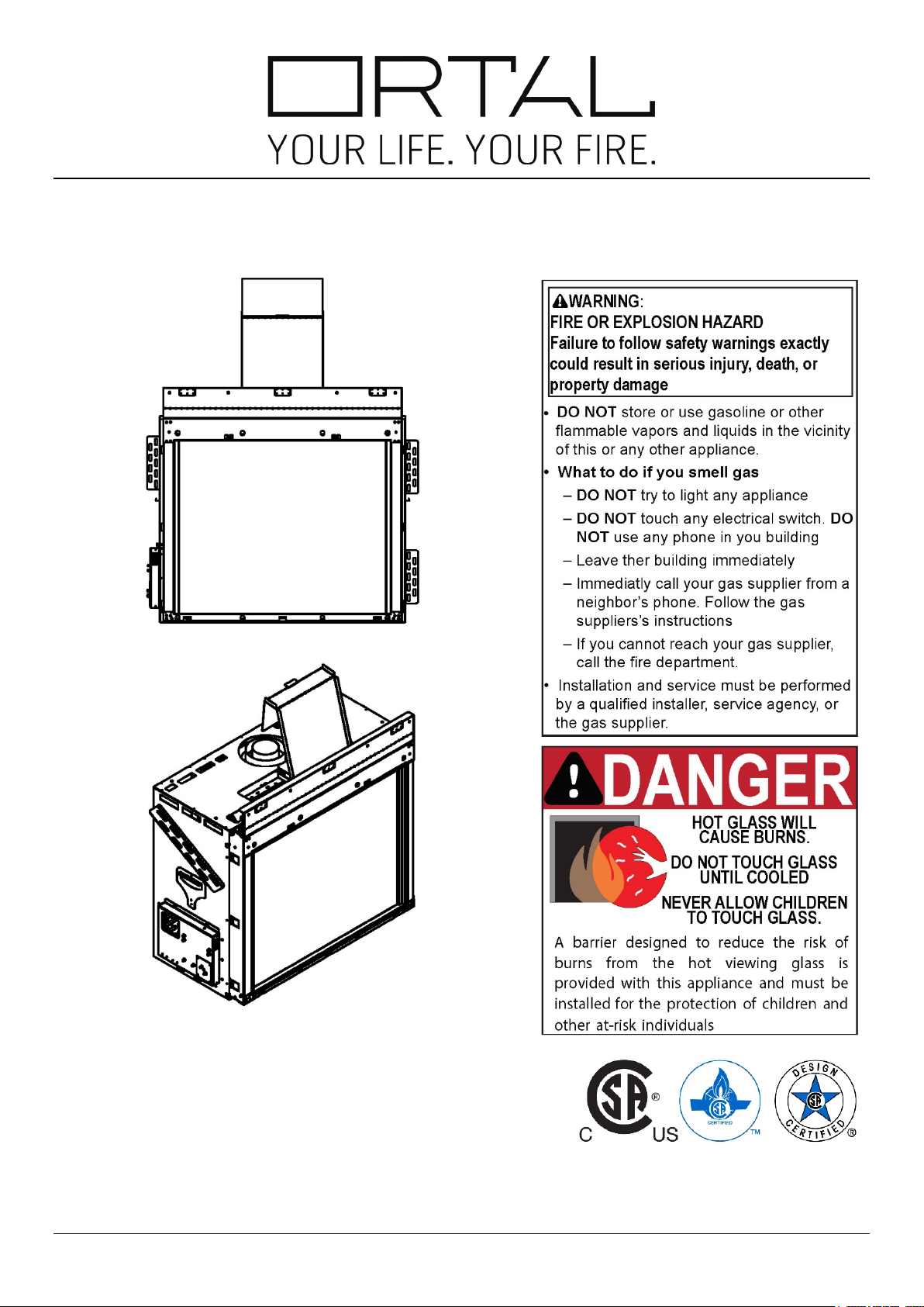
Installation and Operation Manual
Wilderness Traditional Series
Wilderness Traditional Series:
Wilderness Traditional 36
Wilderness Traditional 42
Ortal Installation Manual: Wilderness Traditional Series (V1)
General
Safety Information and Warnings
WARNING: REVIEW ALL WARNINGS
Be sure to review all safety warnings and installation guidelines contained in this manual. Consider installation location, vent
configuration, clearances, structural requirements, framing and finish materials, and local codes. ALL warnings and instructions apply
to all products manufactured and distributed by Ortal.
WARNING: DO NOT OPERATE FIREPLACE IF:
The glass is NOT properly secured in place; Connection points are not sealed (for fireplaces with glass-to-glass connections);
Glass is cracked; You smell gas; Any part of the fireplace has been under water; You have any doubt about safe operation of the
fireplace; Or if any part has been under water, do not use the fireplace. Immediately call a qualified, professional service technician
to inspect the fireplace and to replace any parts of the control system and any gas controls which have been under water.
WARNING: ELECTRICAL GROUNDING
All electrical connections must be properly installed, insulated, and secured to avoid potential ELECTRICAL SHOCK and FIRE
HAZARD and malfunction of the system. Consult local building code requirements. In the absence of local codes, refer to the National
Electric Code, ANSI/NFPA 70, or the Canadian Electric Code, CSA C22.1.
WARNING: MATERIAL USAGE
All materials and objects used to carry out the installation must be certified/approved or specified by Ortal and are suitable for use.
Do NOT install the system with different materials or objects than those approved for installation by Ortal.
WARNING: INSTALLATION AND SERVICE
Installation and repairs on the fireplace and vent system must be done by an authorized Ortal qualified installer service agency or
gas supplier. If these components are not installed by an authorized Ortal dealer/installer, the warranty of all components will be void
and Ortal will not be responsible for any damage caused by improper installation. The fireplace should be inspected before use and
at least annually by a professional service person. More frequent cleaning may be required due to excessive lint from carpeting,
bedding material, etc. Control compartments, burners and circulating air passageways of the fireplace must be kept clean. Any
alteration to the product can cause soot or carbon to form and may result in damage. This damage and any other damage that results
from not following the instructions outlined in this manual is not the responsibility of Ortal.
WARNING: HEAT BARRIER
A barrier designed to reduce the risk of burns from hot viewing glass is provided with this fireplace and shall be installed. The fireplace
MUST not be used without the heat barrier in place. If the barrier becomes damaged, the barrier shall be replaced with the
manufacturer’s barrier for this fireplace. Any safety screen, guard, or barrier removed for servicing the fireplace must be
replaced before operating.
WARNING: FIREPLACE TEMPERATURE
Due to hot temperatures, the fireplace should be located out of traffic and away from furniture and draperies.
Children and adults should be alerted to the hazards of high surface temperature and should stay away to avoid burns or clothing
ignition. Clothing or other flammable material should not be placed on or near the fireplace. Young children should be carefully
supervised when they are in the same room as the fireplace. Toddlers, young children, and others may be susceptible to
accidental contact burns. A physical barrier is recommended if there are at-risk individuals in the house. To restrict access to a
fireplace or stove, install an adjustable safety gate to keep toddlers, young children, and other at-risk individuals out of the room and
away from hot surfaces.
WARNING: GLASS HANDLING
Only an Ortal certified installer is authorized to remove the glass using a suction cup supplied by Ortal.
WARNING: INSTALLATION AND OPERATION
The fireplace and accompanying components must be installed as an OEM installation in manufactured homes (USA only) or an
aftermarket permanently located, or a mobile home, where not prohibited by local codes. The fireplace must be installed in
accordance with the Manufacturer's instructions and the Manufactured Home Construction and Safety Standard, Title 24 CFR, Part
3280, in the United States, or the Standard for Installation in Mobile Homes, CAN/CSA Z240 MH Series, in Canada. Exceeding the
restrictions imposed in these instructions may result in a fire or explosion, causing property damage, personal injury, or
loss of life. Ortal will not be responsible for any damage caused by improper installation. Do not store or use gasoline or
other flammable vapors and liquids near this fireplace.
WARNING: GAS FIREPLACE
This fireplace is for use only with the type of gas indicated on the rating plate. These fireplaces are not convertible for use with other
gases unless a certified kit is used, and the conversion is performed by an authorized and qualified technician. Applicable standards
are Vented Gas Fireplace Heaters ANSI Z21.88 / CSA 2.33a and Gas-fired Fireplaces for Use at High Altitudes CAN/CGA 2.17-M91
2

Table of Contents
General 2
Safety Information and Warnings 2
Product Information 5
Certification 5
Model 5
Rating Label 5
Zero-Clearance Stand-Offs 6
Fireplace Legs 6
Installation 7
Prior to Installation 7
Locate the Fireplace 7
Fireplace Installation 7
First Trip to Site: Planning 7
Second Trip to Site: Installation 7
Third Trip to Site: Startup 8
Post-Installation 8
Initial Burning Period 8
Final Inspection Procedure 8
Final Checks and User Instruction 8
Building Around the Fireplace 9
Building Checklist 9
Framing 10
Framing Dimensions 10
5/8” Type X Drywall Requirements 11
Platform 11
General Clearances 11
Heat Release 13
Air Intake 15
Mounting a TV/Artwork 17
Chase Area Minimum 18
Recessed Ledge Detail 19
Structural Weight Support 20
Step-by-Step Chase Construction 21
Finishing 22
Non-Combustible Finish 22
Combustible Finish
Combustible Floor/Hearth Extension 26
24
Venting 27
General Venting Requirements 27
Vent Installation 27
Vent Clearances 28
Offset Maximum 28
Vent Configuration Diagrams 29
Vent Restrictor Sizing Guidelines 30
Restrictors and Vent Arrangement 31
Vent Termination 32
Horizontal Termination Clearance Diagram 32
Vertical Termination Clearance Diagram 33
Chimney Shroud 34
Co-Axial to Co-Linear Conversion 34
Vent Configuration 35
Vent Maintenance 35
Gas 36
Gas Pressures 36
Routing the Gas Line 36
Access Panel 36
Gas Conversion 37
High Altitude Requirements 37
Gas and Electrical Components 37
3

Electrical 38
Electrical Requirements 38
Pairing the Remote and Receiver 39
Wiring Diagrams 40
Carbon Monoxide Detector Wiring Diagrams 43
Smart Home Wiring Diagram 44
Driftwood Log Set 45
Log Placement for Traditional 36 46
Log Placement for Traditional 42 50
Log Base Position Adjustment 55
Adjustment Instructions 56
Operation 60
10-Button Remote Control Handset 60
Wall Switch 61
myFire App 62
Fireplace Maintenance 63
General Maintenance 63
Troubleshooting 63
4
Product Information
Products:
Natural Gas
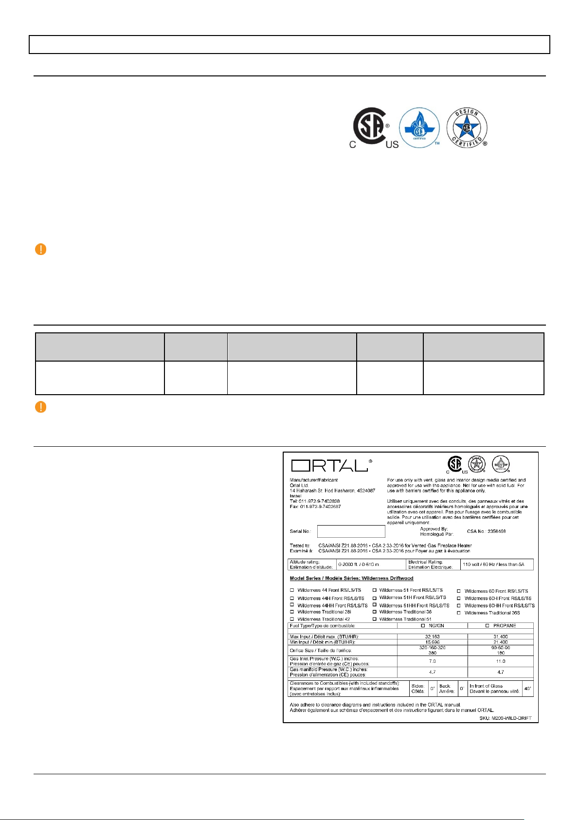
The fireplace rating label is found on a metal plate separate
information is required for servicing and receiving
Wilderness Driftwood Log Set Rating Label
Certification
The Wilderness Traditional Series fireplaces have been tested and approved by CSA Group for safety and efficiency for use with
Natural Gas (NG) and Propane (LP) only, and NOT for use with solid fuels. CSA Group is approved by the American National
Standards Institute (ANSI) as an Accredited Standards Developer.
Certification Standard:
US: ANSI Z21.88 – 2016: Vented Gas Fireplace Heater
Canada: CSA 2.33 – 2016: Vented Gas Fireplace Heater
CLASS 2901 84: DOMESTIC HEATERS (GAS) Vented Fireplace: Certified to US Standard
CLASS 2901 04: DOMESTIC HEATERS (GAS) Vented Fireplace
The fireplaces are permitted for indoor use only. “Indoor” is defined as a conditioned space. The fireplaces are not approved for
outdoor or partial outdoor installation. The fireplaces must be installed while maintaining required clearances. Installation is
recommended in living spaces such as bedrooms, living rooms, great rooms, etc. The fireplaces are not approved for closet
installation. The fireplace must be installed according to Ortal requirements in addition to any local codes that may apply, such as
USA: ANSI Z223.1/NFPA 54, Canada: CSA B149.
IMPORTANT:
Consult the authority having jurisdiction to determine the need for a permit prior to starting the installation.
It is the responsibility of the fireplace dealer and installer to ensure that this fireplace is installed and framed in compliance
with these instructions and all applicable codes.
Before starting, take careful note of ALL the WARNINGS in this manual.
Model
Models Burner Certification Standard
Available
Gas Types
Venting
Wilderness Traditional 36
Wilderness Traditional 42
NOTE: Venting is not supplied by Ortal with the fireplace. The fireplace is certified to be used with, and can be obtained
from, the vent manufacturers outlined in “General Venting Requirements” section.
Driftwood
Rating Label
included with the fireplace.
DEALERS/INSTALLERS: You MUST leave the fireplace’s
rating label with the fireplace in an area easily accessible by
the owner. You must instruct the owner before handing over
the fireplace where this label can be found.
OWNERS: Make sure the installer leaves your fireplace’s
rating label in an area that is easily accessible for you. This
replacement parts.
US: ANSI Z21.88 - 2016
Canada: CSA 2.33 - 2016
or
Propane
5”x8” Co-axial Direct Vent
5
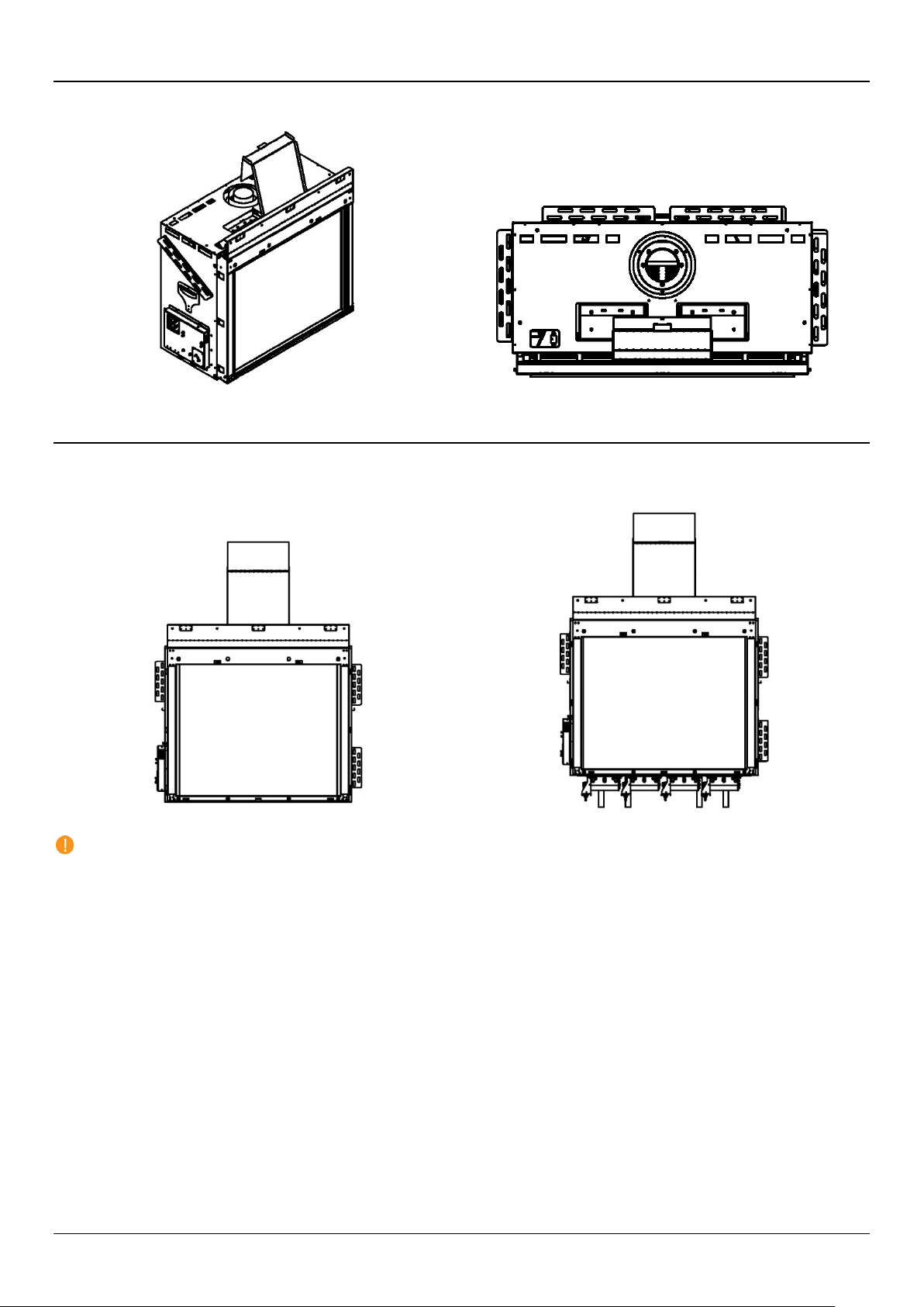
Zero-Clearance Stand-Offs
Zero-Clearance Stand-Offs (Isometric View)
Zero-Clearance Stand-Offs (Top View)
Screen Fireplace
Double Glass Fireplace
The fireplace has zero-clearance stand-offs fastened to the body of the fireplace as shown in the figures below. Stand-offs must be
fully extended upon installation.
Fireplace Legs
The Traditional series fireplace legs varies by heat barrier choice. The screen fireplace does not come with legs and can sit directly
on the floor. The double glass fireplace has legs (measuring 9-13/16” from the bottom of the legs to the bottom of the viewing area)
to allow for space and airflow for the double glass fans. The legs cannot be cut, removed, or altered in any way.
NOTE: Clearances and finish requirements are the same for both heat barrier options. Building requirements (such as
framing values and air intake) may vary.
6
Installation
Prior to Installation
Locate the Fireplace
Keep the following factors in mind when selecting a location for the fireplace:
Fireplace clearance requirements (review “General Clearances” sections).
Heat release and air intake requirements (review “Heat Release Requirements” and “Air Intake Requirements” sections).
Adequate space for servicing.
Minimum vertical vent rise, allowed horizontal lengths, and degree of offset (review “Venting” section).
Framing and finishing requirements (review “Framing” and “Finishing” sections).
Front wall installation and finishes to be completed after fireplace and vent installation (review “Step-By-Step Chase
Construction” section).
Floor or Platform requirements (review “Platform” section).
Fireplace Installation
Use the following guidelines to ensure a smooth installation. The installation sequence is divided into three phases: Planning,
Installation, and Startup.
First Trip to Site: Planning
Consult with the contractor and go over all requirements:
Chase framing requirements.
5/8” Type X Drywall (or equivalent) requirements.
Heat release requirements.
Air Intake requirements (if applicable).
Gas and electric specs and location.
Vent configuration.
Finishing details.
NOTE: Provide the contactor with a copy of the “Building Checklist” and review requirements with them.
Second Trip to Site: Installation
Confirm the following items are properly located and built to specification:
Framing (with 5/8” Type X Drywall as applicable)
Platform
Gas and electric
Heat release
Air intake (if applicable)
Clear a path free of any possible obstruction to carry in the fireplace.
Uncrate the fireplace and set in place.
Make sure all zero-clearance metal stand-offs on the outside of the fireplace are fully extended.
Secure the fireplace to the framing by attaching the nailing flanges to the framing. See “Securing the Fireplace” section
below.
Remove all zip ties.
Connect the light grounding cable to an area on the fireplace closest to the .
Install the vent components. See “Vent Installation” section below.
Review the front wall requirements (see “Step-By-Step Chase Construction” section) and finishing details with the contractor.
Protect the fireplace and components from damage.
7
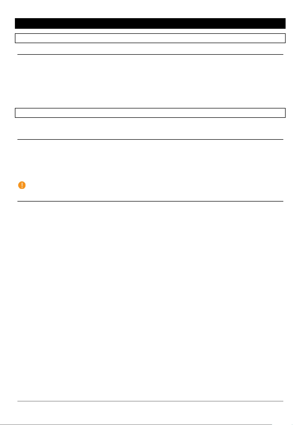
Securing the Fireplace
sealant.
The fireplace has three nailing flanges attached to the top of the front stand-off
(highlighted in grey on “Nailing Flanges” image). The nailing flanges are to be attached
into the framing upon installation. It is crucial to the finishing that the fireplace is stable,
level, and plumb.
Optional for double glass fireplaces: For added stability re-use the shipping brackets to
secure the legs of the fireplace to floor/platform.
Vent Installation
Venting must be installed according to the requirements detailed in the “Venting”
section of this manual in conjunction with the vent system manufacturer’s installation
instructions. Venting must be supported by the structural surrounding and not by the
fireplace. Each offset (elbow) must be strapped to reduce movement or possible
disconnection.
The first section of venting must be secured to the fireplace starter collar with a
minimum of 3 sheet metal screws no longer than ½”. DO NOT use silicone to seal the
sections. If sealing is required by the vent manufacturer or local code, use Mil-Pac
Third Trip to Site: Startup
Perform a visual inspection to confirm that all work was completed correctly and per specification.
Confirm that gas and electric are properly connected and live.
Remove the safety barrier and glass and clean the inside of the fireplace.
Install the Driftwood Logs on the burner as specified in “Log Placement” section.
Confirm the log placement is set up per specification.
Confirm the fireplace is operating properly.
Check remote-control setup.
Remove protective layer from glass.
Clean glass.
Reinstall the glass and safety barrier.
Review operation of the fireplace and remote control with the owner.
Set up return visit to clean glass after the Initial Burning Period (see “Post Installation” section below).
Nailing Flanges
Post-Installation
Complete the following post-installation steps upon 4th trip to site.
Initial Burning Period
There is a 12-hour minimum burning period following installation of the fireplace. This 12-hour period must include a minimum of 4
consecutive hours of continuous burning. During this time, the owner or installer may notice:
The glass developing a white or “cloudy” film
An unusual smell
Both the film and the smell are due to the paint on the fireplace metal heating and “burning off”. This is normal. The cloudiness and
odor will disappear after the 12-hour period elapses and the installer returns to service the fireplace and complete startup.
Final Inspection Procedure
When the 12-hour burning period is complete, the installer must return and perform the final inspection, which includes:
Cleaning the glass with a ceramic glass cleaner (otherwise the white film will remain)
Checking the interior media setup
Checking for gas leaks
Adjusting the restrictor (if necessary)
Performing an overall check to make sure that everything is working properly
When these activities are complete, initial startup is concluded and the fireplace may be operated by the owner.
Final Checks and User Instruction
Before releasing the fireplace to the customer for use without installer supervision, the installer must ensure that the fireplace is
burning correctly. In addition, the installer must review and explain the following to the owner:
Safety warnings
Fireplace operation
Warranty requirements
Maintenance requirements
Glass is hot during and after operation
If any questions or concerns arise, owner must contact the local Ortal dealer/installer for support.
8

Building Around the Fireplace
Building Checklist
The following building checklist is a quick reference for a typical Ortal Wilderness Traditional Series
installation. This list is not exhaustive and does not supplement thorough review of the installation manual.
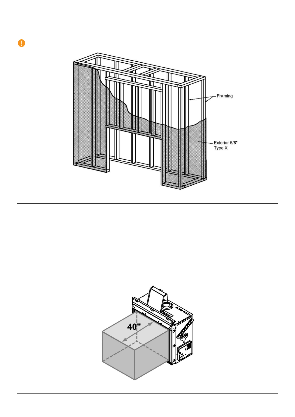
Fireplace Location: Ensure the location allows for min. 40” clearance from viewing area to furniture
and other combustibles. Make sure a clear path is established to allow the fireplace to be safely
transported to installation location.
Venting: Confirm vent size (5”x8”), vent clearance (1” on sides and bottom, 3” on top), vent
configuration, and termination location.
Platform Height: Determine desired fireplace viewing area location on the wall. Average height of
bottom of glass to the floor is 12”-24”. Platform must be able to bear the weight of the fireplace. Platform
can be constructed out of wood, concrete, metal, or any other solid materials (not required to be noncombustible). A platform is not required. The fireplace may sit directly on the floor. The floor has the
same construction requirements as a platform.
Chase Construction: No materials can be attached directly to the fireplace (exception: 5/8” Type X
Drywall). Chase interior must be large enough to accommodate fireplace with all metal stand-offs fully
extended. The area of the chase interior must be min. 124 square inches at any given point within the
chase.
Framing: Adhere to minimum framing dimensions (or greater). Maintain min. ¼” clearance from front
face of fireplace and front metal off-set to the framing. For recessed fireplaces, do not exceed 12” max.
front overhang depth limit. No material is permitted to extend past the ½” metal lip surrounding the
fireplace viewing area.
5/8” Type X Drywall Requirements: One layer of 5/8” Type X Drywall (or equivalent) must be installed
on the exterior of the chase framing. 5/8” Type X Drywall (or equivalent) may be fastened to the front
face of the fireplace with 1" self-tapping drywall screws 16'' on center a minimum of 2 ½” from the metal
lip (above the viewing area).
TV/Artwork: TV/Art must be min. 12” above top of fireplace viewing area.
Gas Supply Line and Power Location: Locate gas line with manual shut off according to local code.
Power provided by single gang 120V outlet in same area as gas line.
Heat Release: Crucial for Cool Wall Technology. Must start within 6” (max.) from the chase’s ceiling.
Min. heat release size is 124 sq.in. of net free air space. Height of the heat release must not exceed 1/3
of the width.
Air Intake: Only required for double glass heat barrier. Must be located at or below level of double glass
fans. Min. 124 sq.in. of net free air space.
Finishing: Maintain required clearances depending on your finish material.
9
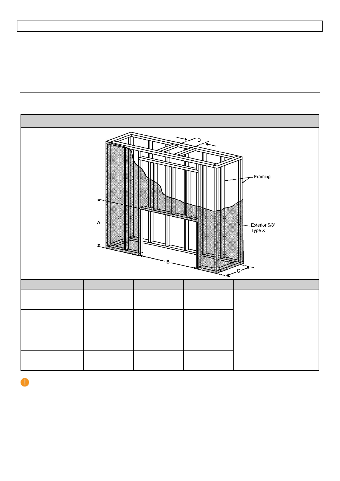
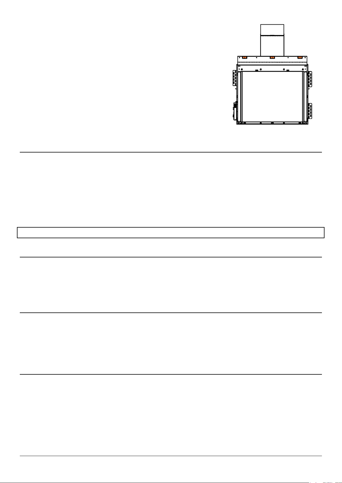
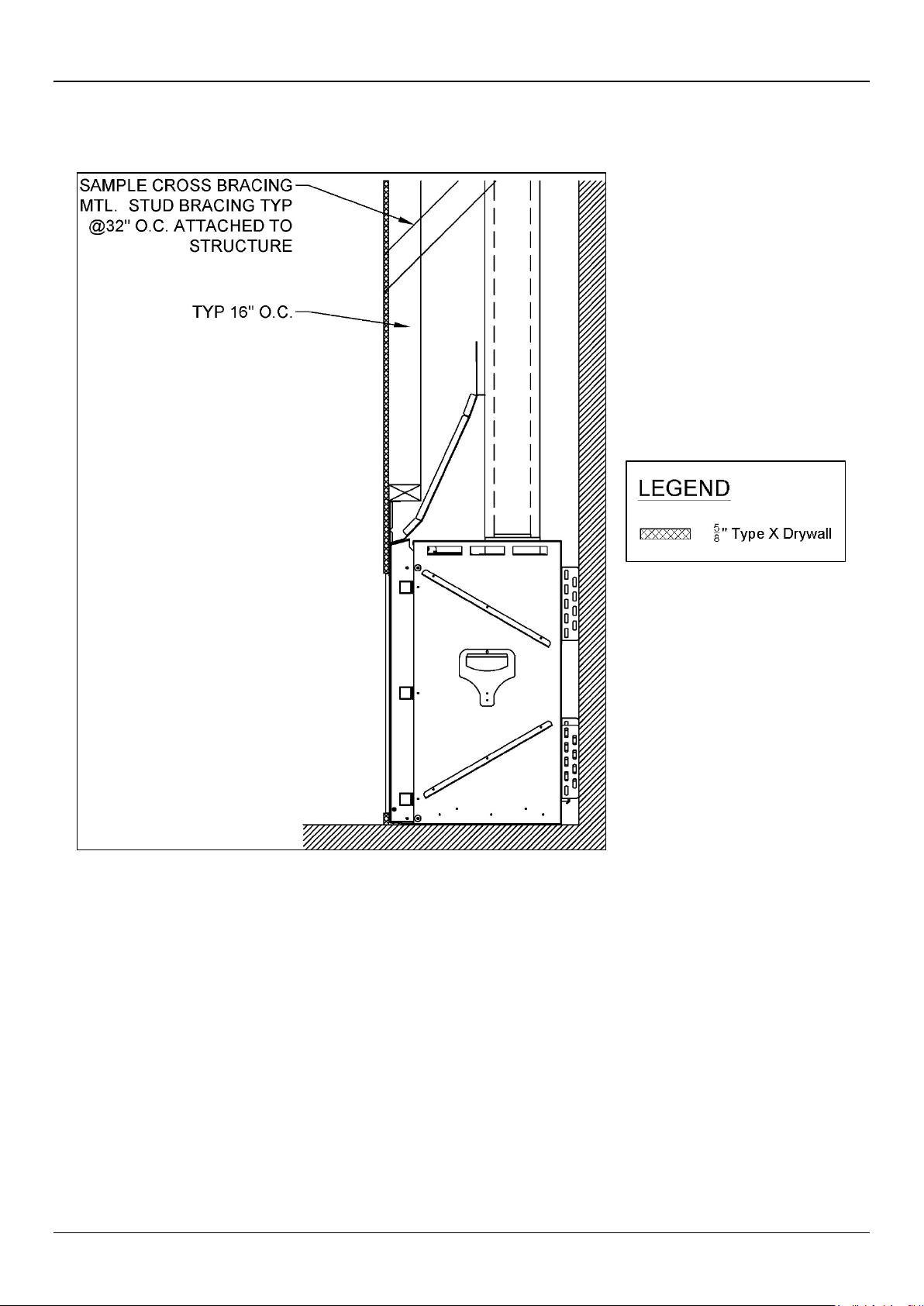
Framing
Fireplace chase may be framed with either combustible (typically wood studs) or non-combustible framing (typically metal studs).
The framing of the fireplace chase must be designed to carry the entire weight of the wall and finish material. Surrounding material
must not transfer weight to the fireplace or be connected in any way to the fireplace, with the exception of 5/8” Type X Drywall (or its
equivalent). It may be fastened to the front face of the fireplace with 1" self-tapping drywall screws 16 inches on center, with a
minimum of 2 ½ inches from the metal lip.
No material is permitted to extend past the ½” metal lip surrounding the fireplace viewing area. This area must be unobstructed to
allow the heat barrier and inside glass panel to be removable.
Framing Dimensions
The following diagrams are for illustrative purposes only. There are multiple approved installation scenarios. A flush application is not
the only permitted application. The fireplace may be recessed into the wall. Refer to diagrams and values below and in the following
pages for details.
Wilderness Traditional Series Framing
Model Dimension A Dimension B Dimension C Dimension D
Wilderness TR 36
(Screen)
Wilderness TR 36
(Double Glass)
Wilderness TR 42
(Screen)
Wilderness TR 42
(Double Glass)
NOTE: Framing dimensions are the same for combustible and non-combustible framing.
43-5/8” 45-13/16 27”
51-3/4” 45-13/16” 27”
Refer to pipe manufacturer’s
firestop dimensions
46-1/8” 53-5/16” 27”
54-1/4” 53-5/16” 27”
10
5/8” Type X Drywall Requirements
Framing must be covered with 5/8” Type X Drywall (or equivalent). The chase interior does not require a layer of 5/8” Type X Drywall
(or equivalent). The chase interior does not require a non-combustible layer.
NOTE: 5/8” Type X Drywall (or equivalent) is not required on the exterior portion of an insulated outside-facing wall.
Platform
The fireplace must be installed on a flat, solid, continuous surface. Surface can be wood, concrete, metal, and other typical solid floor
types. Surface material is not required to be non-combustible.
To raise the fireplace higher than standard height, build a platform to which the fireplace can be secured. Platform must be stable
and able to bear the full weight of the fireplace. Platform can be constructed out of wood, concrete, metal, or any other solid materials.
Material is not required to be non-combustible.
To lower the fireplace, it must be recessed into the floor. Fireplace legs on double glass fireplaces cannot be removed, cut, or
adjusted. Screen fireplaces sit directly on the floor without legs. Platform requirements apply to both screen and double glass
fireplaces.
General Clearances
Non-Combustible Zone
Furniture and other combustibles are not permitted within the non-combustible zone. The non-combustible zone is an area that
extends 40 inches perpendicular from the fireplace glass. Combustibles are permitted below and around the non-combustible zone
Non-Combustible Zone
11
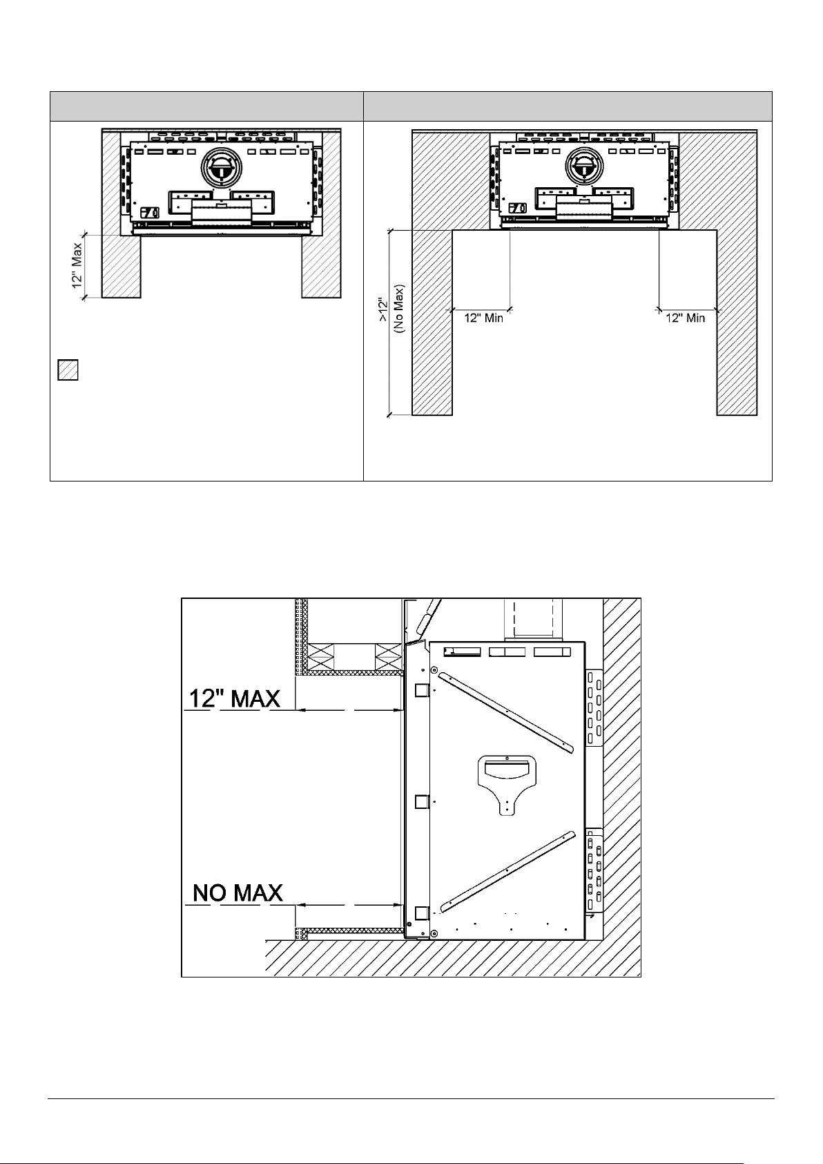
Clearance to a Side Wall
Clearance: No clearance required.
Clearance: Minimum 12-inch clearance required between the side
The following requirements apply to a wall perpendicular to the front glass of the fireplace.
Side Wall ≤ 12 inches
Top View
Building Material
wall and the side viewing area lip.
Side Wall > 12 inches
Top View
Maximum Overhang Depth
Overhang depth of a recessed fireplace must not exceed 12 inches. Overhang depth is measured from the edge of the fireplace lip
to the out-most part of the wall (including finish material). Overhang framing and finish materials may be either non-combustible or
combustible.
Bottom recess (or “hearth extension”) has no minimum or maximum depth requirement. If bottom recess depth exceeds 12 inches,
ensure the structure is capable of supporting the weight of a fireplace technician for servicing.
12
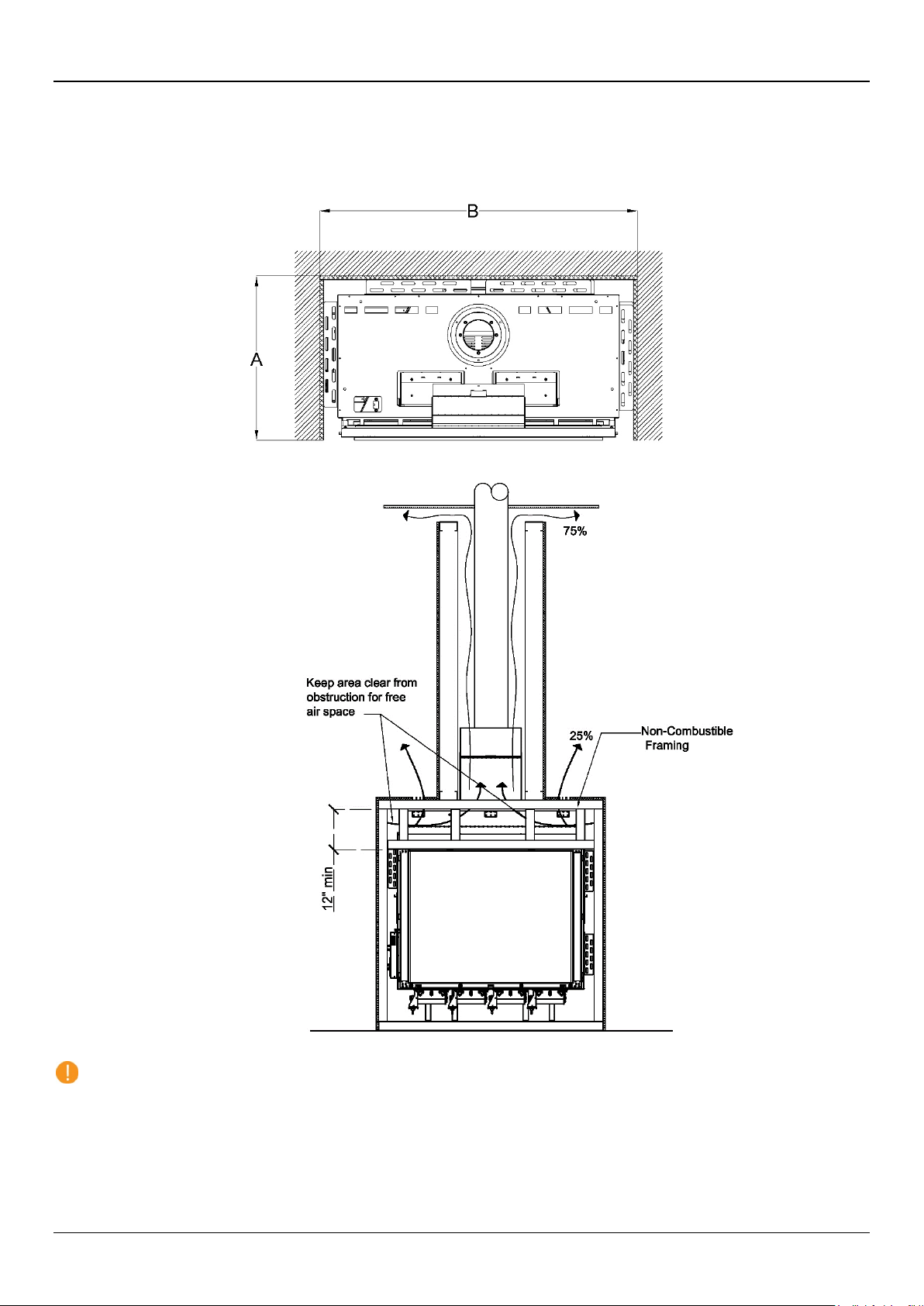
Heat Release
Gap Heat Release
Louvered Grille Heat Release
A heat release is an opening in the fireplace chase that allows the heat inside the chase to passively circulate into an interior room.
This heat is generated convectively as the fireplace heats up. It is separate from exhaust heat produced at the combustion chamber
of the fireplace. A heat release is required to keep the wall around the fireplace cool.
Heat Release Requirements
The heat release must be located at or near the top of the fireplace chase and start within 6 inches (0-6 inches max) of the
chase ceiling (draft stop). It can start at the chase ceiling. It can be located on the front, sides or back of the chase. It can
be released into any interior space that shares a wall with the chase.
The heat release cannot be vented outdoors as this would expose the fireplace to outdoor elements.
Minimum heat release size requirement depends on heat release orientation:
Horizontal Heat Release Vertical Heat Release
Minimum 124 sq. in. of net free air space Minimum 160 sq. in. of net free air space
For horizontal heat releases, the height of the heat release must not exceed 1/3 of the width. The heat release must be 2/3
wider than it is tall.
The heat release can be in the form of (but not limited to) a louvered ventilation grille, gap, or reveal.
For louvered ventilation grilles, the net free air space allowed in the louvered area must be equal or greater than
the minimum number of square inches required per fireplace.
The interior area of the narrowest part of the fireplace chase (in square inches) must never be less than your required heat
release size (see “Chase Area Minimum” section for details).
The following diagrams are examples of potential heat release options. These drawings serve as illustrative purposes only.
Horizontal Heat Release
13
Vertical Heat Release: Split Front
Vertical Heat Release: Full Side
The heat release is oriented vertically and split between the two
sides of the chase.
The heat release is oriented vertically. Entire heat release is
on one side of the fireplace chase.
Split Front Vertical Heat Release
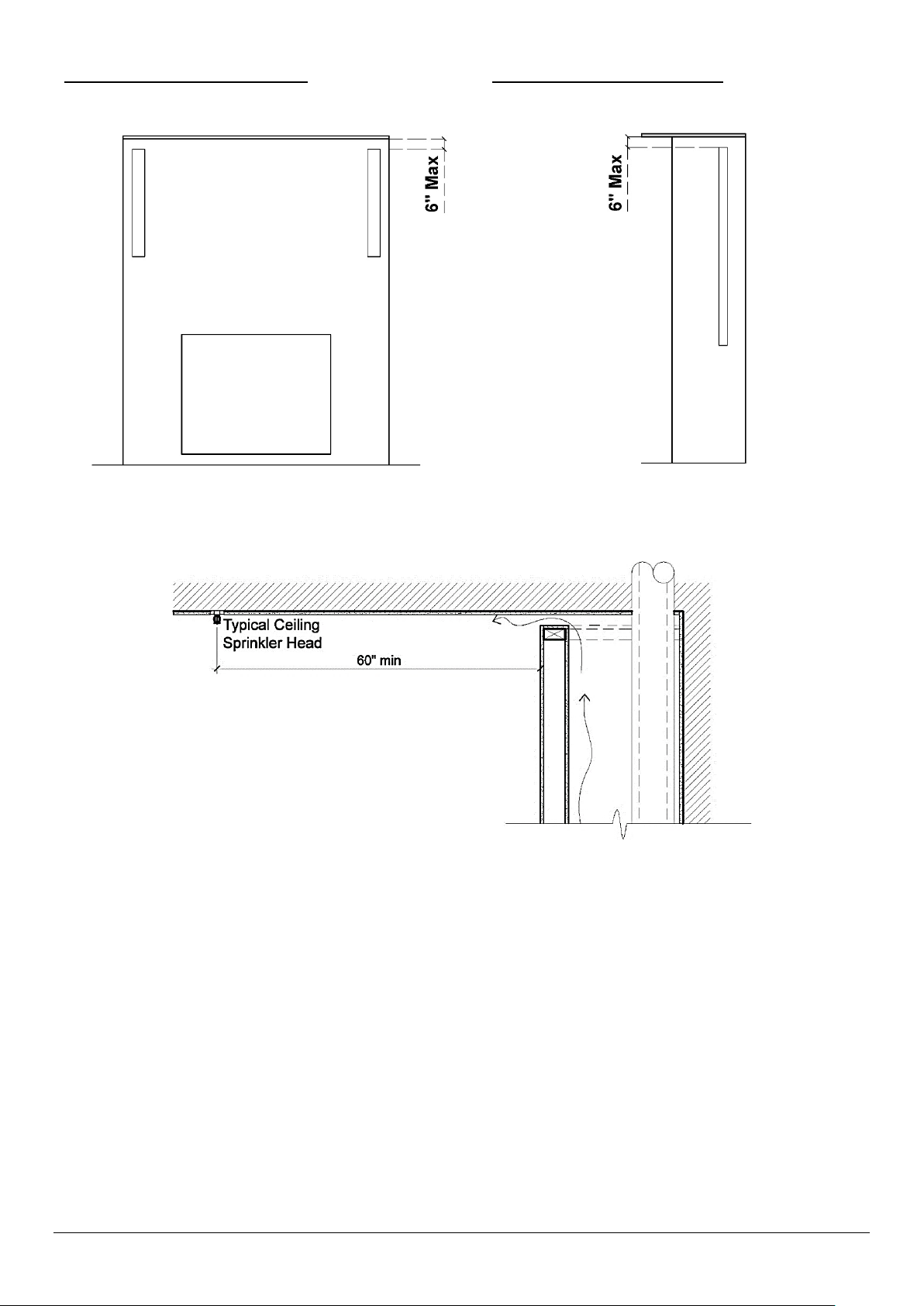
Sprinkler Clearance to Heat Release
In a situation where a sprinkler head is
from every point of the heat release opening.
near
the heat release, the sprinkler head must be minimum 60 inches (linear length)
Full Vertical Heat Release on One Side
14
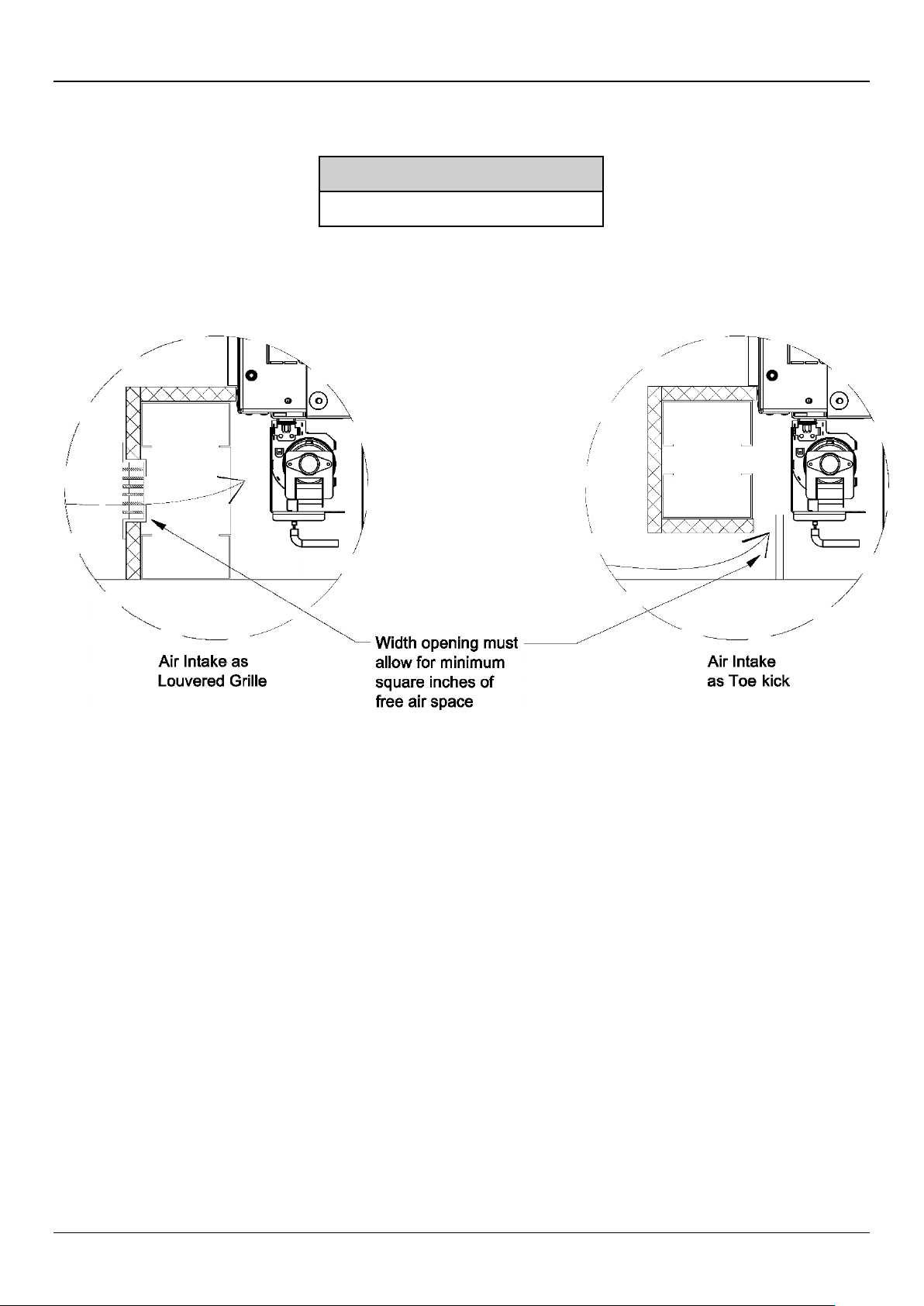
Air Intake
When installing a fireplace with a double glass heat barrier, it is essential to maintain cool air flow between the double glass panels.
For this purpose, an opening must be provided toward the bottom of the wall to allow the double glass fans to circulate room air
through the glass panels and up into the chase. This opening, called an air intake, needs to be made before closing the wall surface
below the fireplace. Air intake must meet the minimum size requirement.
Air Intake
Minimum 124 sq. in. of net free air space
The air intake can be in the form of a louvered ventilation grille, gap, or toe-kick (reveal). For louvered ventilation grilles, the net free
air space allowed in the louvered area must be equal or greater than the minimum number of square inches required per fireplace.
The entire air intake must be located at or below the double glass fans. The air intake is not required to be on the front wall of
the fireplace. The air intake cannot be on a wall that allows air from outside the house directly into the fireplace chase.
15
Air Intake for a Platform
NOTE: Please refer to the “Platform” section for details on platform construction.
16
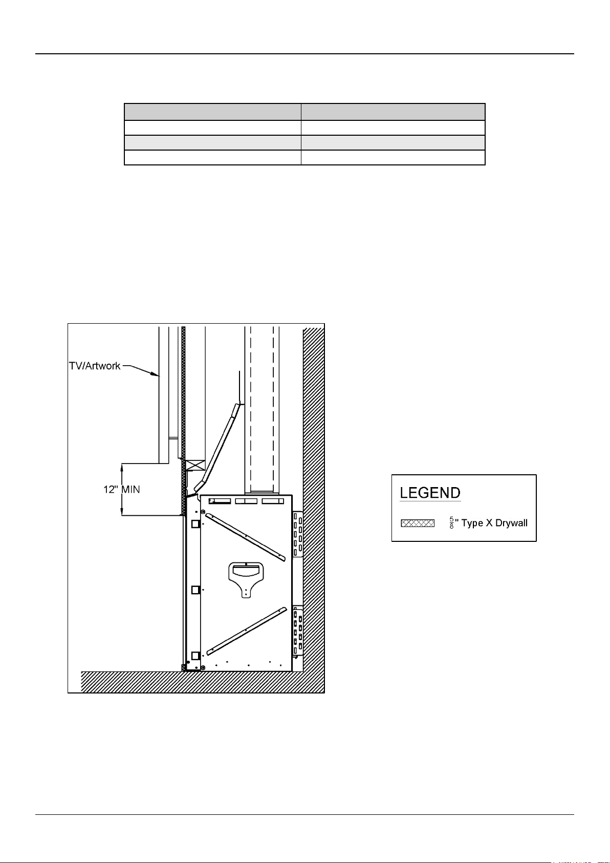
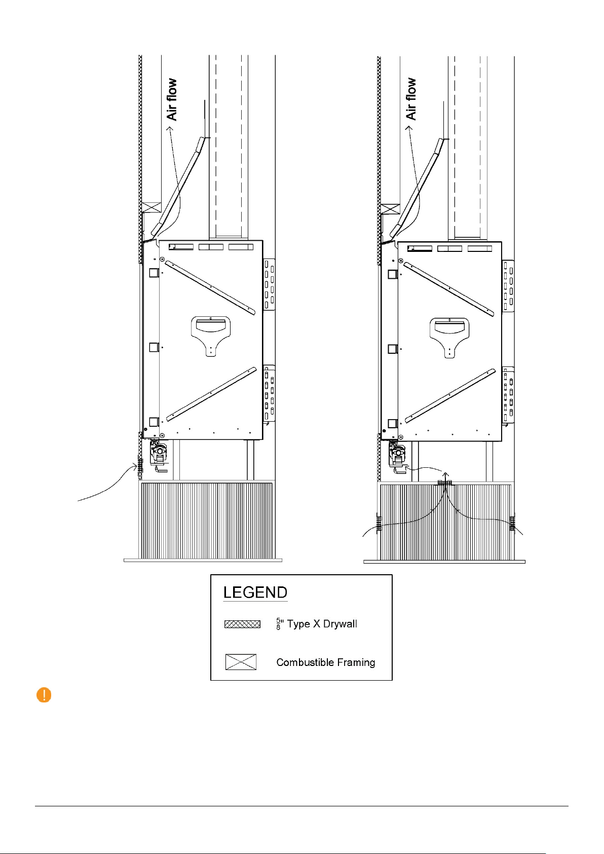
Mounting a TV/Artwork
0-6 inches above fireplace
100˚F - 120˚F
12 inches above fireplace
80˚F - 90˚F
Required minimum clearance between bottom edge of TV or other similar device or
artwork and top of fireplace viewing area is 12 inches.
Ortal’s Cool Wall Technology is a technique that reduces the convective heat from the fireplace and prevents heat buildup inside the
fireplace chase, mitigating any damage that may result from the wall reaching high temperatures. Ortal’s Cool Wall system enables
the option of safely installing artwork, a TV, or other similar electronic components above the fireplace by reducing the wall
temperature above the fireplace.
Location Wall Temperature
6-12 inches above fireplace 90˚F - 100˚F
Maintain the following general requirements to mount a TV or artwork above the fireplace and prevent heat damage:
Mount the TV or artwork a minimum of 12 inches above the top of the fireplace viewing area.
TV wires must be routed through framing and cannot pass through the fireplace chase.
The decision to install a television above an Ortal fireplace is up to the discretion of the owner. TV and art manufacturers may specify
that their product should not be installed on, near or above a heat source. Ortal will not be held liable for any adverse effects on a
TV, artwork or other equipment located near the Ortal fireplace. It is the owner’s responsibility to verify that their TV or artwork can
withstand the wall temperatures as outlined in the above wall temperature chart.
The following diagrams can be used as a guide for customers who do decide to locate their TV and artwork above their Ortal fireplace.
These drawings illustrate ways of reducing the amount of heat impact to the area surrounding the fireplace.
Flush Mounted TV/Artwork
17
Recessed TV/Artwork
Chase Area Minimum
To ensure the convective heat within the chase passively moves to the heat release at an optimal rate, all parts of the interior of the
chase must be minimum 124 sq. in. in size at any given point. To determine if your chase meets this requirement, use the following
equation at the narrowest part of the chase.
Chase Area = (Chase Length x Chase Depth) – (50.27in2)
Fireplace Chase (Top View)
If the heat release is split into 25/75 portions due to an oversized ledge, the chase only needs to be the size of 75% of the heat
release because 25% of the heat is already being released at the ledge (see “Ledge Detail” section below for details).
18
Recessed Ledge Detail
A ledge over the top of a fireplace that is less than 24 inches from the top of the fireplace viewing area must maintain a minimum
12 inches from the top of the viewing area to the bottom of the building material. Entire structure must be non-
of
combustible (framing and finish).
If ledge surface area exceeds
at the ledge and 75% at the chase ceiling.
220 sq.in
., the heat release must be divided up between the ledge and the chase ceiling: 25%
Ledge Size: A x B ≤ 220 sq. in.
A = ledge depth, B= ledge length (Top View)
Oversized Ledge Detail
NOTES:
Top portion of the top front stand-off must be removed. See “Recessed TV/Artwork” section for details.
Chase area minimum requirements must be met throughout the entire fireplace chase. See “Chase Area Minimum” section
above for details.
19
Structural Weight Support
The fireplace must not carry any structural weight. The framing must be supported by another surface. Consult with the project
structural engineer and refer to your local building codes for proper wall support.
The following drawing shows a recommended approach to this type of installation. Please note that these drawings are not to scale.
All fireplace drawings with correct dimensions are available on the Ortal website.
20
 Loading...