

ORTAL Clear 40 Tunnel, Clear 40 LS, Clear 40H90 RS, Clear 40H90 LS, Clear 40H90 TS Installation & Operation Manual
...
®
INSTALLATION & OPERATION
MANUAL

2
BALANCED FLUE APPLIANCES
USER, INSTALLATION AND SERVICING
INSTRUCTIONS
IMPORTANT - THE COMBUSTION CHAMBER OF THIS STOVE
SHOULD ONLY BE OPENED AND SERVICED BY A REGISTERED GAS
INSTALLER ,
and should not be used if the Glass is broken, and never be
use with the front open.
Please read these instructions carefully before installation or use, and leave with
the customer for storage is a safe place for future reference.
This appliance has been designed and approved for use in other countries
than shown on this cover. To install in other countries it is essential to
obtain the manual in the local translation. Contact ortal
ire for further information.
14 Harash St. Neve Neeman, Hod
Hashron, 45240, Israel P.O Box 7213
Tel: +972-9-7402828
Fax: +972-9-7402687
E-mail: ortalsys@netvision.net.il
ORTAL Heating Solutions Ltd.
INSTALLATION & OPERATION MANUAL
Instruction for Burner 30 Models:
Clear 40, Clear 40 RS/LS/TS, Clear 40 H
Clear 40 Tunnel, Stand Alone 40 TS
ORTAL Heating Solutions Ltd.
INSTALLATION & OPERATION MANUAL
Instruction for Burner 30 Models:
Clear 40, Clear 40 RS/LS/TS, Clear 40 H
Clear 40 Tunnel, Stand Alone 40 TS
WARNING: Glass Handling
The glass must ONLY be removed by an authorized &/or qualified installer. The
authorized technician should ONLY remove the glass with the glass vacuum holders
supplied b the manufacturer. Lower the glass to rest in the special
wooden/polyurethane support provided, and fit the second support to the upper edge of
the glass. This is to pre ent damage to the glass edges.
Step 1. Place the support on the floor below the glass to be removed.
Step 2. Remove the glass using the vacuum holder, and immediately place it in the
support.
Step 3. Place the second support on the upper edge of the glass. The glass can
now be rested safely.
WARNING: Electrical Grounding
These Direct Vent appliances must be electrically grounded in accordance with the
local codes or, in the absence of local codes, with National Electric code, ANSI/NFPA
70, or the Canadian Ele tric Code, CSA C22.1.
WARNING: Gas Appliance
This applian e is only for use with the type of gas indicated on the rating plate. These
appliances are not convertible for use with other gases, unless a certified kit is used
and the con ersion is performed by an authorized qualified technician.
Applicable standards are Vented Gas fireplace heaters ANSI Z21.88 / CSA 2.33a and
gas-fired appliances for use at high altitudes CAN/CGA 2.17-M91.
ORTAL Heating Solutions Ltd.
INSTALLATION & OPERATION MANUAL
Instruction for Burner 30 Models:
Clear 40, Clear 40 RS/LS/TS, Clear 40 H
Clear 40 Tunnel, Stand Alone 40 TS
ORTAL Heating Solutions Ltd.
INSTALLATION & OPERATION MANUAL
Instruction for Burner 30 Models:
Clear 40, Clear 40 RS/LS/TS, Clear 40 H
Clear 40 Tunnel, Stand Alone 40 TS
WARNING: Glass Handling
The glass must ONLY be removed by an authorized &/or qualified installer. The
authorized technician should ONLY remove the glass with the glass vacuum holders
supplied b the manufacturer. Lower the glass to rest in the special
wooden/polyurethane support provided, and fit the second support to the upper edge of
the glass. This is to pre ent damage to the glass edges.
Step 1. Place the support on the floor below the glass to be removed.
Step 2. Remove the glass using the vacuum holder, and immediately place it in the
support.
Step 3. Place the second support on the upper edge of the glass. The glass can
now be rested safely.
WARNING: Electrical Grounding
These Direct Vent appliances must be electrically grounded in accordance with the
local codes or, in the absence of local codes, with National Electric code, ANSI/NFPA
70, or the Canadian Ele tric Code, CSA C22.1.
WARNING: Gas Appliance
This applian e is only for use with the type of gas indicated on the rating plate. These
appliances are not convertible for use with other gases, unless a certified kit is used
and the con ersion is performed by an authorized qualified technician.
®
This manual covers the following appliances:
Single burner:
Clear 40 RS/LS/TS/Tunnel, Stand Alone 40 TS, Clear 40H90 RS/
LS/TS/Tunnel,
Clear 40H70 RS/LS/TS/Tunnel, Small Square, Corner Classic/ Modern , 4 glass
Island, Clear 75 RS/LS/TS, Stand Alone 75 /TS, Space Creator 75, Clear 75 Hark
RS/LS/TS, Clear 75x65 /Tunnel, Clear 60x80 /Tunnel, 60x80 OVAL, Classic F
75/80, Clear 80 RS/LS/TS, Clear 80H70 RS/LS/TS, Clear 110 RS/LS/TS/Tunnel,
Stand Alone 110, Clear 110H /Tunnel, Clear 130 RS/LS/TS/Tunnel, Space Creator
120, Island 130, 130 Top, Clear 150 RS/LS/TS/Tunnel, Space Creator 150, Stand
Alone 150, Clear 170 RS/LS/TS/Tunnel, Clear 200 RS/LS/TS/Tunnel, Space
Creator 200, Clear 250 RS/LS/TS/Tunnel, Clear 200H70 RS/LS/TS
Two burners:
Clear 250 RS/LS/TS/Tunnel, 4 glass 2 burners Clear 350 RS/LS/
TS/Tunnel, Clear 300H80 RS/LS/TS, Clear 400 RS/LS/TS/Tunnel, Clear 400H80
RS/LS/TS, Island 400
Contents
GENERAL INFORMATION . . . . 4
Important Safety Notice . . . . 4
General Fitting Information . . . 5
Battery type (Remote Versions only) . . 5
INSTALLER INFORMATION . . . . 5
Ventilation . . . . . 5
General Balanced Flue notes . . . 6
Terminal Locations Wall mounting . . 8
Terminal Locations Roof termination . . 9
Commissioning the appliance . . . 10
Servicing Instructions . . . . 10
Spare parts 11
Troubleshooting . . . . . 12
Countries of destination 13
Table B-2 Double Category 15
Instructions for changing burner from NG to LPG 16
TECHNICAL INFORMATION . . . . 21
Technigas CE approval test results 21
Contents- Single Step Burner (N) 21
Contents- Double Step Burner (D) 22
minimum clearances to combustibles materials . 23
DECORATION ARRANGEMENT . . . 30
English Branch . . 31
Logs (5 pes set) . . 36
White Little Stons . . 41
Large Pebbles . . 45
NEW LOGS ( 6 pcs SET) 1 SET . . 49
Flue Design Options . . 54
Automatic Valve information . . 59
I
mportant Safety notIce

5
The Building Regulations issued by the Department of the Environment, the
Building Standards (Scotland) (Consolidation) Regulations issued by the Scottish
Development Department.
BS 1251, BS 5440 part 1, BS 5871 part 2, BS 6461 part1, BS 6891 and BS 8303
In the Republic of Ireland the installation must also conform to the relevant standards,
particularly in regard to ue sizing and ventilation. Refer to documents IS813, ICP3,
IS327 and any other rules in force.
This appliance must be installed in accordance with the rules in force and used only
in a sufciently ventilated space, and is intended for use on a gas installation with
a governed meter.
Before installation, ensure that the local distribution conditions (identication of the
type of gas and pressure) and the adjustment of the appliance are compatible. The
technical specication of this appliance is given on the rear page of this manual.
This appliance should not be used if the Glass is broken, and should never
be used with the Door open.
General Fitting Information
Inlet Pipe connection 8mm Compression
Chimney requirement Balanced Flue
Flame monitor Permanent Pilot
User control: Variable rotary control inc. integrated Piezo ignition, Permanent pilot
facility, Flame failure device and Oxygen Depletion Cut-out.
Before installation of these appliances, the area into which the re is to be tted
must be cleared of all debris (including dust), in particular combustible material.
The appliance must sit on a hearth (or base surface) sufcient to support the weight
of the re. The rebox must then also be secured. Adjustable brackets are supplied
on the rebox for this purpose.
Battery type (Remote Versions only)
Receiver: 4x AA, R6 size.
Transmitter: PP3 (Alkaline only).
If the Flame Supervision Device is extinguished either
intentionally or unintentionally, no attempt should be made to
re-light the gas until at least 3 minutes have elapsed.
Ventilation
4
NEW LOGS ( 6 pcs SET) 1 SET . . 49
Flue Design Options . . 54
Automatic Valve information . . 59
Important Safety notIce
This appliance has a ceramic Fire-bed arrangement; this contains Refractory
Ceramic Fibres, which are man-made vitreous silicate bres. Excessive exposure
to these materials can cause irritation to eyes, skin and respiratory organs. Hence
we recommend that when handling these materials the release of dust should be
kept to a minimum. During installation and servicing we recommend that a HEPA
ltered vacuum be used to remove any dust and soot in and around the re. If any
of the ceramic re-bed components need to be replaced we recommend that the
removed parts be sealed in a heavy-duty polythene bag, and be labelled as RCF
waste. RCF is not “Hazardous waste” and can be disposed of at a licensed tipping
site for the disposal of industrial waste.
The appliance incorporates a permanent pilot. This is located on the front of the
burner, and must not be adjusted by the installer. This system must not be put out
of operation, and if any parts require changing, only original manufacturer parts
shall be used.
This appliance is designed to be used either Natural or LPG gas however, each
individual appliance is only capable of running off the type of gas specied at the
time of purchase. It is important to note that once a type of gas has been specied
the stove cannot run off any other type. The type of gas that your stove is capable
of burning is stated on the data information panel.
This appliance has been designed, tested and approved to meet standards in place
for product use, performance and safety. Installation of your appliance must comply
with current building regulations. It is therefore recommend that a registered gas
installer be employed for this task. The engineer will provide you with information
about the safety limits of the installation and should x a notice plate in a place
where it can be readily seen.
This appliance is designed as an efcient heating device and consequently all body
parts become very hot in use. Except for the control knob and control access door,
which are designed to stay cool, all other parts are working surfaces and should
not be touched.
The glass and frame on this appliance acts as a reguard conforming to BS: 1945
– 1971 and satises the Heating Appliance (Fireguards) regulations 1991. No
part of the window or frame should be permanently removed. It does not give full
protection for young children or the inrm, extra protection should be considered for
these conditions conforming to BS 6539 or BS 6778.
Bearing in mind that the heat given off by this appliance may affect articles placed
close to it, curtains should not be placed within 30cm.
The appliance is not designed as a dryer. It is not therefore recommended that the
appliance be used in such a manner. Do not place any articles within 30cm of this
appliance as this may result in damage to the articles.
The installation must be carried out in accordance with the following regulations:
The Building Regulations issued by the Department of the Environment, the
Building Standards (Scotland) (Consolidation) Regulations issued by the Scottish
Development Department.

7
If the appliance is located in a recess, then the recess must have adequate
ventilation, we recommend a minimum total vent area of 600 cm².
The stove must be located at least 280mm from any combustible materials.
Timber Frame Construction
Whilst it is possible to install room-sealed appliances in timber frame properties,
great care needs to be taken to ensure that the ue assembly does not interfere
with the weather proong qualities of any outer wall which it may penetrate. Before
attempting this work, further details need to be referenced, (e.g. “Gas Installations
in Timber Frame Buildings” from the CORGI installer series in the UK).
Carport or Building Extension
Where a ue terminal is sited within a carport or building extension, it should have
at least two completely open and unobstructed sides. The distance between the
lowest part of the roof and the top of the terminal should be at least 600mm.
Note: A covered passageway should not be treated as a carport. Flues should not
be sited in a covered passageway between properties.
Basements, Lightwells and Retaining walls
Flue terminals should not be sited within the connes of a basement area, light well
or external space formed by a retaining wall, unless steps are taken to ensure the
products of combustion can disperse safely at all times. It may be possible to install
this Balanced Flue system in such a location provided that it is not sited lower than
1m from the top level of that area to allow combustion products to disperse safely.
Flue terminals should be sited to ensure total clearance of the combustion products
in accordance with the enclosed information.
When the products of combustion are discharged, they should not cause a nuisance
to adjoining or adjacent properties and they should be positioned so that damage
cannot occur to other parts of the building. If the outer wall surface is constructed of
combustible material, a non-combustible plate should be tted behind the terminal
projecting 25mm beyond the external edges of the terminal.
6
This appliance can be installed in a completely sealed or mechanically ventilated
house without extra ventilation and/or fume extraction.
General Balanced Flue Notes
There are many possibilities for installing this Concentric Balanced Flue system
into a building, both Roof and Wall terminations are possible, and the ue can
either be built into an existing chimney or a completely new ue system may be
constructed.
The system is based upon a Concentric Flue system which utilises an inner ue of
100/130mm diameter which passes through an outer ue of 150/200mm diameter.
The ue gasses that are the products of combustion of the re, pass through the
inner ue and are safely vented to the outside environment. The gap between the
inner and outer ues is the channel by which the stove is supplied with air for
combustion.
These concentric ues terminate outside of the property in a terminal, this terminal
will keep the expelled gasses and the fresh air for combustion separate. It is
important that the terminal is not blocked, a suitable guard maybe required if the
terminal is located at a “Low” level (usually when the terminal is within 2m of oor
level).
The Balanced Flue gas appliance can be installed as an insertion into an existing
or new replace. If an existing Flue or Chimney is to be utilised, then the installation
engineer must be consulted. If the chimney has been previously used it must be
professionally cleaned and certied as being sound and t for use.
The European CE approval on this appliance is restricted to the Flue systems as
specied by the supplier, thus the appliance must only be installed with the original
ue system, no others may be used
The gas re, in combination with the concentric ue system, has been approved
in accordance with the European CE-norm for gas appliances and may therefore
be used only with this system. The guarantee is invalidated if the appliance is
(completely or partially) installed using a different system.
The concentric ue systems can be used with either a newly-built or existing
chimney.
These appliances are designed with the “Firebox” raised up off the ground level by
the built in “Base unit”.
Thus these appliances require no special Hearth arrangements, as the oor will not
get hot and is protected by the steel construction of the “Base unit”.
The appliance must not be tted against a rear wall constructed from a combustible
material; a gap of 300mm should be given all round the stove before combustible
materials may be used in the wall construction.
If the appliance has to be located in an opening, a minimum clearance of 50mm
should be allowed to non-combustible materials.

9
Terminal Locations Roof Termination
“Distance” = minimum distance required for positioning of the outlet to avoid adverse
effects with respect to:
A. A ventilation opening serving an occupied room, a toilet or a bathroom
B. A heating air supply, when the supply ows through an occupied room.
C. A window that can be opened and that is near an occupied room, a toilet
or a bathroom.
(*) If the required distance cannot be achieved, the outlet position rules take
precedence.
(**) If the outlet is positioned at least 1 m higher than the intake supply opening, or
a window that can be opened.
(***) If the required distance cannot be achieved, the position of the outlet must be
at least 1 m above the highest facade/roof.
Important note for Roof Terminations, (C31).
When installing the appliance with a roof termination (classication C31), it is
important to t a 30mm ue restriction strip across the ue outlet inside the stove.
Dist ance: outlet -
A,B or C
At the same roof level >6 m (*)
At a different roof level >3 m (*) (**)
At a lower positioned wall >2 m (**)
At a higher sloping surface >6 m (***)
To avoid advers e effects
8
Terminal Locations Wall Mounting
* In addition, the terminal should not be nearer than 300mm to an
opening in the building fabric formed for the purpose of accommodating
a built in element such as a window frame.
Dimensi on Terminal P osit ion
Dist ance (mm)
A* Directl y below an opening, air bric k, openi ng window etc. 600
B Above an opening,air bric k, opening window etc . 300
C Adjacent to an opening, air brick , opening window etc. 400
D Below gutt ers, s oil pipes or drain pipes 300
E Below eaves 300
F Below balc onies of c ar port roof 600
G From a vert ical drai n pipe or soil pipe 300
H From an internal or ex ternal c orner 600
I Above ground roof or balcony level 300
J From a s urface facing t he terminal 600
K From a t erminal faci ng the term inal 600
L From an openi ng in the c ar port (e.g. door , window int o the dwelli ng)
1200
M Vertical ly from a t erminal on t he same wall
1500
N Horizontall y from a term inal on the s ame wall 300
INSTALLER INFORMATION
Dimen ion Terminal Po ition Di tan e ( mm)
A* Directl below an opening,air bri k, opening window etc. 600
B Abo e an opening,air bri k, opening window et . 300
C Adjacent to an opening,air brick, opening window et . 400
D Below gutters, soil pipe or drain pipe 300
E Below eave 300
F Below balconie of car port roof 600
G From a vertical drain pipe or soil pipe 300
H From an internal or external corner 600
I Abo e ground roof or balcon le el 300
From a surface facing the terminal 600
K From a terminal facing the termina l 600
L From an opening in the car port (e.g. door , window into the dwelling) 1200
M Verticall from a terminal on the same wall 1500
N Horizontall from a terminal on the same wall 300
P From a vertical stru ture on the roof 600
Q Abo e inter ection with roof 150

11
Burner – 30 Clear 40 RS/LS/TS/Tunnel, Stand Alone 40 TS, Clear 40H90 RS/LS/TS/
Tunnel, Clear 40H70 RS/LS/TS/Tunnel, Small Square, Corner Classic/ Modern ,
Burner- 45 Clear 75 RS/LS/TS, Stand Alone 75 /TS, Space Creator 75, Clear 75 Hark
RS/LS/TS, Clear 75x65 /Tunnel, Clear 60x80 /Tunnel, 60x80 OVAL, Classic F 75/80, Clear
80 RS/LS/TS, Clear 80H70 RS/LS/TS, 4 glass Island
Two Burner- 45 4 glass 2 burners
Burner- 100 Clear 110 RS/LS/TS/Tunnel, Stand Alone 110, Clear 110H /Tunnel, Clear
130 RS/LS/TS/Tunnel, Space Creator 120, Island 130, 130 Top
Two Burner- 100 Clear 250 RS/LS/TS/Tunnel
Burner- 135 Clear 150 RS/LS/TS/Tunnel, Space Creator 150,
Stand Alone 150, Clear 170 RS/LS/TS/Tunnel
Two Burner- 135 Clear 350 RS/LS/TS/Tunnel, Clear 300H80 RS/LS/TS
Burner- 160 Clear 200 RS/LS/TS/Tunnel, Space Creator 200, Clear 250 RS/LS/TS/
Tunnel, Clear 200H70 RS/LS/TS
Two Burner- 160 Clear 400 RS/LS/TS/Tunnel, Clear 400H80 RS/LS/TS, Island 400
Spare Parts
Pilot Burner
Injector Pilot N.G
Injector Pilot L.P.G
Injector burner 30 N.G
Injector burner 30 L.P.G
Injector Burner- 45 N.G
Injector Burner- 45 L.P.G
Injector Burner- 100 N.G
Injector Burner- 100 L.P.G
Injector Burner- 135 N.G
Injector Burner- 135 L.P.G
Injector Burner-160 N.G
Injector Burner-160 L.P.G
Thermo couple 100
Thermo couple 120
Thermo couple 150
Gas regulator block GV60
Ignition cable 2x(2,8x0.5) L=1000
Ignition cable 2x(2,8x0.5) L=1500
Ceramic electrode
Pilot pipe Ø4mm
Remote
10
COMMISSIONING THE STOVE
A soundness test MUST be made before the installed stove is left with the
customer.
Ensure that the re is burning at full rate for a minimum of 5 minutes to warm the
ue.
If there are problems, the ue may require attention.
The stove will produce an odour and/or smoke for the rst few hours of use. Please
ventilate the room. Also please note that during this initial burning period, a grey
dust deposit will be formed on the inside of the glass, please clean this before
leaving the appliance with the customer
Servicing inStructionS
The following outlines only the minimum work that should be performed on an
annual basis. This service work, like any other work on the appliance, must only be
done by a qualied and competent engineer who is CORGI registered.
Open the door and remove all ceramics.
Remove mat from top of burner.
Remove any debris from the top of the burner using a vacuum cleaner and brush.
Inspect the burner unit.
Perform an ignition check.
Perform a ame failure check
There should be no need to service the burner. If however this is required, then the
engineer should check the setting pressure at inlet to burner; the correct pressure
is shown at the rear of the manual.
Brush off and replace ceramic arrangement as earlier in this manual, replacing any
broken or damaged pieces.
Check all seal on door (including glass) and replace the Door.
Check the installation for gas leaks.
Check ue for clearance of products of combustion.
If any parts need to be replaced use only genuine manufacturer parts, non-standard
parts will invalidate the guarantee and may be dangerous.

13
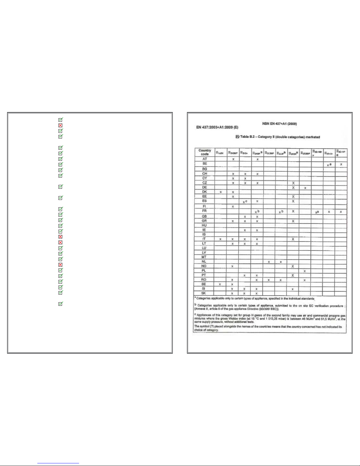
Countries of Destination
The following tables gives detail of the Countries that these appliances are approved
for use within. The tables following immediately on give the technical characteristics
of the appliances.
Natural
AT Austria
þ I2H G20@20mbar
BE Belgium þ I2E+ G20/G25@20/25mbar
CH Switzerland þ I2H G20@20mbar
CY Cyprus ý
CZ Czech Republic þ I2H G20@20mbar
DE Germany þ I2E G20@20mbar;
I2ELL G20/G25@20mbar
DK Denmark þ I2H G20@20mbar
EE Estonia þ I2H G20@20mbar
ES Spain þ I2H G20@20mbar
FI Finland þ I2H G20@20mbar
FR France þ I2E+ G20/G25@20/25mbar
GB United Kingdom þ I2H G20@20mbar
GR Greece þ I2H G20@20mbar
HR Croatia þ I2H G20@20mbar
HU Hungary ý
IE Ireland þ I2H G20@20mbar
IT Italy þ I2H G20@20mbar
LT Lithuania þ I2H G20@20mbar
LU Luxembourg þ I2H G20@20mbar
LV Latvia þ I2H G20@20mbar
MT Malta ý
NL The Netherlandsþ I2L G25@25mbar
NO Norway þ I2H G20@20mbar
PL Poland þ I2E G20@20mbar
PT Portugal þ I2H G20@20mbar
RO Romania þ I2H G20@20mbar
SE Sweden þ I2H G20@20mbar
SI Slovenia þ I2H G20@20mbar
SK Slovakia
þ I2H G20@20mbar
TR Turkey þ I2H G20@20mbar
LPG
AT Austria þ I3B/P G30/G31@50mbar
BE Belgium þ I3+ G30/G31@28-30/37mbar
12
Troubleshooting
The gas pilot will not ignite or stay lit?
Ensure the gas is turned on at the appliance and the meter/cylinder.
Depress the control knob for at least twenty seconds once the pilot is alight to
ensure the operation of the safety thermocouple valve.
Ensure that the pilot injector is not obstructed or blocked and it is free from any dust
or dirt.
Ensure that the thermocouple has not been damaged in transit. This is a very
delicate Electro-magnetic device.
On propane, the cylinder could be empty.
The pilot is not burning or performing correctly?
Ensure the pilot ame is the correct size for the type of gas. The ame should be
focused on the thermocouple probe.
The pilot ame will have been set correctly in the factory.
The Main Burner does not seem to be burning correctly?
Ensure adequate gas pressure to the appliance. Test pressure by releasing the
pressure test screw and applying a manometer. Ensure adequate volume of gas is
being used. Once the re is burning on maximum, turn off all other gas appliances
in the house and calculate the fuel being burned from the gas meter.
Make sure that the burner is burning correctly. The ame should be even across
the top of the burner before any coals are placed on top.
1514
CH Switzerland
þ I3B/P G30/G31@50mbar;
I3+ G30/G31@28-30/37mbar
CY Cyprus þ I3B/P G30/G31@30mbar
CZ Czech Republic þ I3B/P G30/G31@50mbar;
I3+ G30/G31@28-30/37mbar
DE Germany þ I3B/P G30/G31@50mbar
DK Denmark þ I3B/P G30/G31@30mbar
EE Estonia þ I3B/P G30/G31@30mbar
ES Spain þ I3+ G30/G31@28-30/37mbar
FI Finland þ I3B/P G30/G31@30mbar
FR France þ I3B/P G30/G31@30mbar;
I3+ G30/G31@28-30/37mbar
GB United Kingdom þ I3B/P G30/G31@30mbar;
I3+ G30/G31@28-30/37mbar
GR Greece þ I3B/P G30/G31@30mbar;
I3+ G30/G31@28-30/37mbar
HR Croatia þ I3B/P G30/G31@30mbar
HU Hungary þ I3B/P G30/G31@30mbar
IE Ireland þ I3+ G30/G31@28-30/37mbar
IT Italy þ I3+ G30/G31@28-30/37mbar
LT Lithuania þ I3B/P G30/G31@30mbar
LU Luxembourg ý
LV Latvia ý
MT Malta þ I3B/P G30/G31@30mbar
NL
The Netherlands
þ I3B/P G30/G31@30mbar
NO Norway þ I3B/P G30/G31@30mbar
PL Poland ý
PT Portugal þ I3+ G30/G31@28-30/37mbar
RO Romania þ I3B/P G30/G31@30mbar
SE Sweden þ I3B/P G30/G31@30mbar
SL Slovenia þ I3B/P G30/G31@30mbar
SI Slovakia þ I3B/P G30/G31@30,50mbar;
I3+ G30/G31@28-30/37mbar
TR Turkey þ I3B/P G30/G31@30mbar
17
using a 10mm spanner. Note - to avoid
damaging the Pilot assembly, this can be held
rm a 12mm spanner.
3.2 The original Pilot Injector
should come out with the pilot tube as it
“hooks” onto the Olive and tube.
3.3 Hook the new Pilot Injector onto
the tube and olive, carefully insert this
into the Pilot assembly.
3.4 Fully tighten the pilot nut.
4. Adjust the Venturi Throttle to a fully open position. To achieve this loosen
the two nuts on top of
the Burner Base, and slide the Venturi Throttle fully towards the Burner
Body. Tighten the nuts.
5. Check the nuts are done up tight.
6. Replace the Burner into the appliance.
7. Connect the Gas Supply.
8. Perform a Soundness Test, to check that there are no leaks.
9. Set the Burner pressure. For this appliance running at FULL on LPG,
the burner pressure must be 29.5 mbar.
16
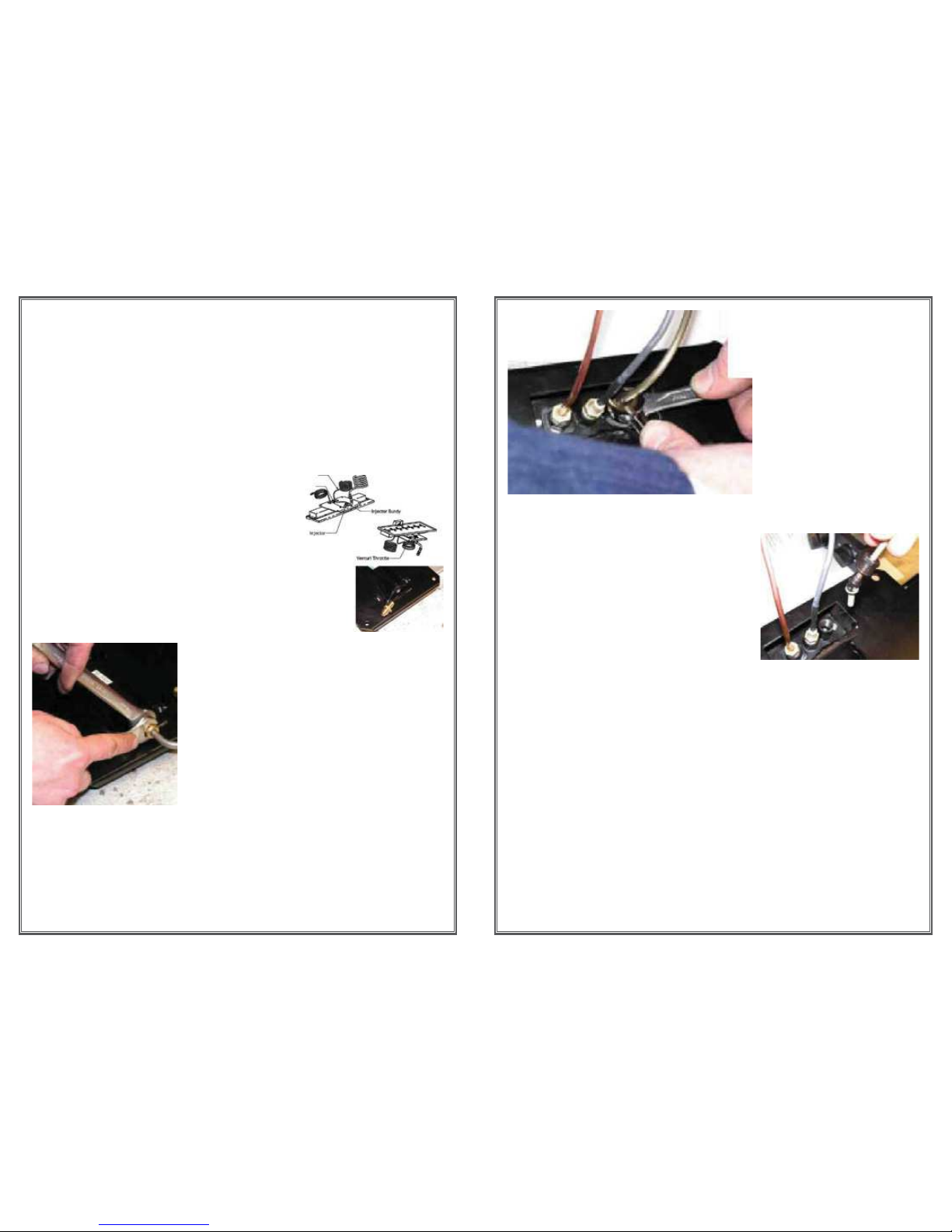
Instructions for changing Burner from Natural Gas to LPG
General Notes
Although it is possible to modify the Burner from Natural to LPG in the
appliance, we would recom mend removing the burner from the appliance.
This is done by removing the door and window, remove the Grate Plates
which will then give access to the burner base. The burner is secured to the
appliance by 4 M6 bolts which should be removed by a 10mm spanner or
socket. The burner is then free to be lifted out.
Procedure
1. Ensure the Gas supply is isolated.
2. Replace the injector.
2.1 Loosen and remove Injector Bundy,
(it will probably be necessary to hold Injector
with a 15mm spanner).
Replace Pilot Injector.
3.1 Loosen and remove Pilot Bundy pipe. This is achieved by loosening
the Pilot Bundy Nut,
2.1 Remove the Injector
2.2 Insert New Injector
2.3 Replace Injector Bundy tube and fully
tighten Injector Bundy Nut.

19
9.2 Setting the burner pressure. There are two different types of control
used for this burner, the FULLY REMOTE and SEMI REMOTE, the
semi remote can only be used for controlling the burner UP or DOWN
it has no ignition facility. The full remote can control the appliance
UP and DOWN, but can also SPARK the IGNITION and turn the
appliance OFF. The pressure measurement and adjustment is the
same for both types of burner, however access to the setting screw is
different for the two types of control.
9.2.1 Access to Fully Remote setting screw. On this version, the
setting screw is accessible through a hole in the front cover of the
control, this maybe blocked I off by a plastic plug, in this case
remove the plug.
9.2.2 Access to Semi Remote setting screw. On this version, it is
necessary to remove the front cover of the control to reveal the
setting screw. First remove the Cross Head Screw shown in the
picture on the left below, and then, using a at head screwdriver prize
the tab over catch as shown on the right below. The cover can now be
removed,
Setting Screw
18
9.1 Measuring the Burner Pressure. The picture below shows
the two Pressure Measuring Tappings available on the control.
There is an arrow by each tapping. The rst arrow points into
the control, this is the Gas Supply Pressure, the second arrow is
pointing outwards from the control.
The Gas Supply pressure is governed by the regulator at the gas
supply, and the pipework to the appliance, this point can be
used to measure the supply pressure at the appliance.
It is the Burner Pressure Tapping that is important for this operation. With
the control in the OFF position, release (but do not remove) the screw inside
the tapping, and connect the tube of the Manometer to the Tapping. Now
ignite the burner.
The value shown on the manometer is the Burner Pressure.
Burner Pressure Tapping
Gas Supply Pressure Tapping

21
Contents- Single Step Burner (N)
1. Injector:
0.30M burner: marked Bray 220 for LPG & Bray 650 for Natural Gas
0.45M burner: marked Bray 220 for LPG & Bray 650 for Natural Gas
1.00M burner: marked Bray 260 for LPG & Bray 1200 for Natural Gas
1.35M burner: marked Bray 380 for LPG & Bray 1400 for Natural Gas
1.60M burner: marked Bray 380 for LPG & Bray 1400 for Natural Gas
0 Pilot injector, marked 23 for LPG & 36 for NG
1 Data Label
Technigas CE approval test results
Natural Gas
LPG
Input
Output
Efciency
%
Efciency
Class
Input
Output
Efciency%Efciency
Class
0.30 m
burner
G20
5.16
kW
G26
5.94
kW
4.44
5.04
85.9
85.0
1
1
5.46 kW4.14 kW75.8 2
0.45 m
burner
G20
G25
7kW
G20
G25
6kW
%85.7
1
G30
5.2
G30
4.3
%82.7
1
1.00 m
burner
G20 8.9
G25
8.3
6.8
6.3
75.9
75.7
2
2
G30
7.5 kW
5.2 72.1 2
1.35 m
burner
10.5 kW9.1 86.8 1 G30
11,9
kW
7,8 65,3 2
1,60 m
burner
G20
12.88
kW
G25
13.00
kW
G20
10.68
G25
10.81
kW
G20
%82.63
G25
%83.14
G20
1
G25
1
G30
12.83
kW
G30
9.30
kW
G30
%72.45
G30
2
20
which reveals the setting screw.
9.2.3 Adjust the setting screw until the Burner Pressure reaches
the required 25.9 mbar. This value should be set when the
Burner has been alight for approximately 10 min utes and
the burner is hot.
10. Apply the supplied Data plate sticker over the technical details over
the Data plate sticker on the appliance, so that the Data plate now
reads correct for LPG.
Setting Screw

23
ORTAL Heating Solutions Ltd.
INSTALLATION & OPERATION MANUAL
Instruction for Burner 30 Models:
Clear 40, Clear 40 RS/LS/TS, Clear 40 H
Clear 40 Tunnel, Stand Alone 40 TS
The Ortal direct vent appliances have been tested and approved by CSA for safety and
efficiency for use with either Natural Gas (NG) or Propane (LP).
e. Review and explain maintenance requirements to customer
f. Review and explain warranty requirements to customer
Locating Your Gas Fireplace
When selecting a location for your fireplace
Ensure that the minimum clearances to combustible materials are met as
outlined in the next section.
Provide adequate clearances for ser icing.
Minimum vent vertical and allowed horizontal lengths and number of bends must
be considered during the location selection for your fireplace.
The applian e must be installed on a flat, solid, continuous surface (e.g. wood, metal,
concrete). This may be the floor or a raised platform to enhance its visual impact. If the
appliance is going to be installed on carpeting, combustible linoleum tile or other
combustible material other than wood flooring, the appliance must be installed on a
metal or wood panel as a barrier above the combustible material extending the full width
and depth of the applian e.
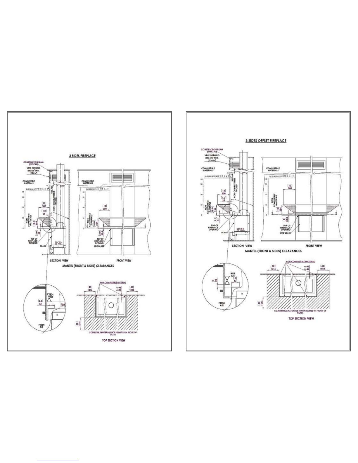
Minimum Clearances to Combustibles Materials
Appliance and Vent Clearances
The appliance is approved with maintained minimum clearance to combustible materials
as shown in the diagrams provided.
Non-combustible materials, such as surrounds and other appliance trim, may be
installed on the appliance face. However, they must not cover any portion of the
removable glass panel or the control compartment.
The minimum clearances (air space) to combustible materials must be adhered to. It is
of the greatest importance that the fireplace and vent system be installed only in
accordance with these instructions.
Vertical installation clearances to combustible mantels vary according to the depth of the
mantel. Mantels constructed of non-combustible materials may be installed at any
height above the appliance opening; however, do not allow anything to hang below the
fireplace hood.
Recommendation: Ortal recommends the use of high temperature paint (rated 175° F
or higher) on the underside of the mantel.
22
Contents- Double Step Burner (D)
1. Injector:
0.30M burner:
0.45M burner: marked Bray 160 + 160 for LPG & Bray 380 + 380 for Natural Gas
1.00M burner: marked Bray 180 + 180 for LPG & Bray 650 + 650 for Natural Gas
1.35M burner: marked Bray 220 + 220 for LPG & Bray front 800 + rear 650 for NG
1.60M burner: marked Bray 220 + 220 for LPG & Bray front 800 + rear 650 for NG
0 Pilot injector, marked 23 for LPG & 36 for NG
1 Data Label
Technigas CE approval test results
LPGNatural Gas
Efciency
Class Efciency
%
OutputInput
Efciency
Class Efciency
%
OutputInput
0.30m
burner
2
1
G20
83.42
G20
6.77
KW
G25
6.76
KW
G20
8.12
KW
G25
8.16
KW
0.45m
burner
G30
G30
5.37
KW
G30
6.99
KW 77
G25
82.89
2
2
G20
78.13
G20
9.80
KW
G20
10.17
KW
1.00m
burner
G30
G30
8.03
KW
G30
8.45
KW 76.88
G25
76.90
G25
10.03
KW
G25
10.23
KW
2
1
G20
82.78
G20
10.99
KW
G20
11.45
KW
1.35m
burner
G30
G30
9.46
KW
G30
11.72
KW 77.7
G25
83.45
G25
11.37
KW
G25
11.58
KW
1
1
G20
86.9
G20
11.36
KW
G20
13.05
KW
1.60m
burner
G30
G30
11.24
KW
G30
13.25
KW 82.3
G25
80.9
G25
10.47
KW
G25
12.93
KW
25
24
CLEARANCE DIAGRAMS
 Loading...