

Page 1

Ortal Heating Solutions
Industrial Area Newe Ne’eman B’
Hod Hasharon 45260 ISRAEL
Tel : +972-9-740 2828
Fax : +972-9-740 2687
E-mail: [email protected]
CELSIUS + MONTANA
OPEN FIRE
USER, INSTALLATION AND SERVICING
INSTRUCTIONS (GB & IE)
IMPORTANT - THE COMBUSTION CHAMBER OF THIS STOVE SHOULD ONLY BE
OPENED AND SERVICED BY A REGISTERED GAS INSTALLER
Please read these instructions carefully before installation or use, and leave with the
customer for storage is a safe place for future reference.
This appliance has been designed and approved for use in other countries than shown on this cover. To install in
other countries it is essential to obtain the manual
Page 2

CONTENTS
GENERAL SECTION
1. DIMENSIONS OF FIRE ........................................................................................... 3
2. TECHNICAL INFORMATION ................................................................................ 3
INSTALLER SECION
3. INFORMATION FOR INSTALLERS ...................................................................... 4
4. SITING THE APPLIANCE ....................................................................................... 5
5. FLUE CONNECTION ............................................................................................... 6
6. VENTILATION (G.B. & I.E. ONLY) ....................................................................... 6
7. CONNECTING THE GAS SUPPLY ........................................................................ 7
8. PRESSURE TESTING .............................................................................................. 7
9. ARRANGING THE LAYOUT OF THE COALS ..................................................... 7
10. TEST FOR SPILLAGE ........................................................................................... 8
USER SECTION
11. OPERATING THE FIRE ......................................................................................... 8
SERVICE SECTION
12. TROUBLE SHOOTING ........................................................................................ 10
13. SERVICING INSTRUCTIONS ............................................................................ 11
14. SERVICE PARTS .................................................................................................. 11
APPENDIX
1. REMOTE CONTROL WITH CLIMATE CONTROL ........................................... 12
2. REMOTE CONTROL ELECTRONIC IGNITION SYSTEM ........................................................... 13
Page 3
3
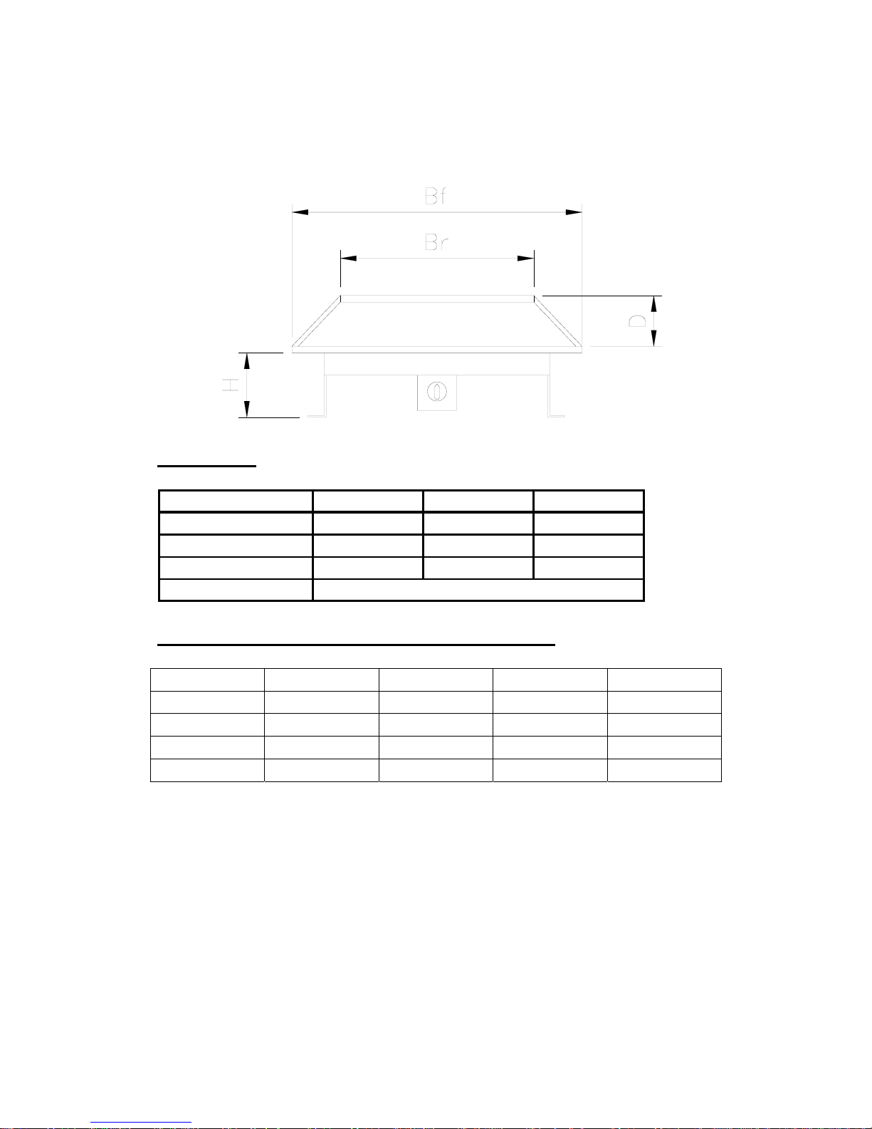
1. ....................................................................... DIMENSIONS OF FIRE
Physical dimensions
MONTANA
Model Small Large Rectangular
Breadth (front) Bf 450 550 365
Breadth (rear) Br 300 400 365
Depth D 200 200 200
Height H
Adjustable
CELSIUS (Ortal versions 1.10m, 1.30m or 1.50m)
Model Small Large Rectangular
Breadth F Bf 1000 1350 N/A
Breadth R Br 1000 1350 N/A
Depth D 200 200 N/A
Height H Varied Varied N/A
2. TECHNICAL INFORMATION
Gas Type Natural G20 / I2H
LPG G31 / I3P
Gas Input Gross See section 2
Pipe connection 8mm via supplied adapter
Manual Option Variable rotary gas control with integrated Piezo
Ignition, permanent pilot facility and flame failure
safety device.
Page 4

4
Remote option Variable rotary gas control with integrated Piezo
Ignition, permanent pilot facility and flame failure
safety device, with appliance mounted eye for remote
control via handset. No external power supply required.
Flue Requirements Class I
Model Small/Large Montana Small/Large Celsius
Gas G20/I2H G31/G30 I3B/P
Input - kW 14 13
S-Pressure - mBar 20 37/29
B-Pressure - mBar 11 36.4 / 28
Gas Rate (m3/Hr) 1.316 0.475
Injector Size 1200 320
GENERAL POINTS FOR THE PURCHASER
This appliance is intended for decorative purposes only.
The Fire is designed to run off either Natural or LPG gas. It is important to note that once a
type of gas has been specified the Fire cannot run off any other type. The type of gas that your
Fire is capable of burning is stated on the data information panel, located on the under side of
the burner.
This burner has an Oxygen Depletion System (ODS), the system is not adjustable, and should
not be rendered in operative. The ODS will stop the supply of gas if the evacuation of flue
gasses is interrupted. If this occurs then a 10 minute period should be allowed before reignition is attempted as described in section 10.1. If this situation recurs then a specialist
should be informed.
If parts of the fire require replacement only original parts must be used. These are available
through the dealer from whom you purchased the Fire.
BEFORE INSTALLING THE FIRE CHECK THAT THE DATA PLATE
INDICATES THE SUITABILITY OF THE TYPE OF GAS BEING
USED. i.e. NATURAL GAS PRESSURE.
3. INFORMATION FOR INSTALLERS
The burner is designed to run on Natural or LPG gas. The burner unit is not interchangeable
between gas types.
Page 5

5
The fire is an open radiant log effect appliance which can be placed directly inside any
fireplace opening of the dimensions stated within the installation instructions.
Important Notes
Ventilation
Any air vent shall be fitted in accordance with national regulations.
These instructions have been compiled in accordance with EN 509.
Ensure that the appliance corresponds to the type of gas it is to be used with. This can be
confirmed by checking the data badge located on the appliance.
It is required that any appliance using gas is installed by a competent person, in conjunction
with the instructions and the requirements as laid down in the relevant Regulations.
The installation must be in accordance with the Gas Safety Installation and Use Regulations
1984 and with these instructions, and all the relevant parts of the Local and National Building
Regulations, and the recommendations of the relevant Codes of Practice.
- The Gas safety (Installation and Use) Regulations
- The Building Regulations
- The Building Standards (Scotland) (Consolidation) Regulations.
APPLIANCE TO BE INSTALLED IN
ACCORDANCE TO NATIONAL REGULATIONS.
All surfaces except the control knob, and lower front door opening knob are considered to be
working surfaces.
FIREGUARD WARNING
PROTECTION FOR YOUNG CHILDREN OR THE INFIRM IS NOT GIVEN
BY THIS APPLIANCE, AND AS SUCH A SUITABLE FIREGUARD SHOULD
BE USED IN THESE CONDITIONS.
Page 6
6
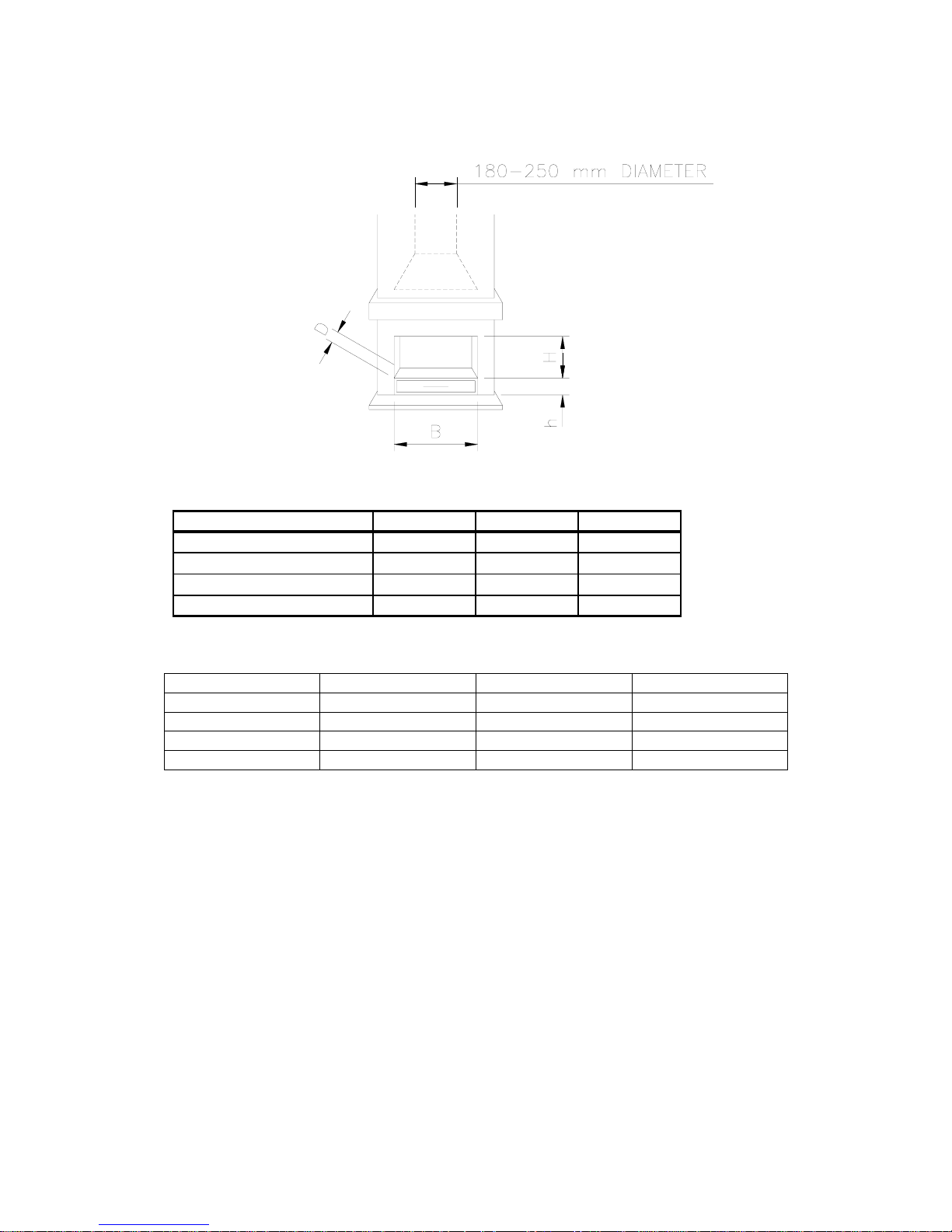
4. SITING THE FIRE
Montana
Celsius (Ortal models 1.10 m, 1.30 m and 1.60 m)
Model Small Large Rectangular
Breadth (max) B 1200 1600 N/A
Height (max) H 350 350 N/A
Burner top h 150 150 N/A
Depth (Max) D 400 400 N/A
The flue height depends on Diameter 180-250mm, for example minimum 3m’ for 250mm, or
6m’ with 200mm Diameter.
The gas connection requires semi rigid pipe (8mm), not more than 1 metre in length.
The appliance can be installed in any adequate area suitable for solid fuel fires and Fires.
The appliance must be located at least 250mm from any combustible materials.
HEARTH
The appliance must stand on a fireproof hearth.
To comply with the Building Regulations issued by the Department of the Environment, the
following points should be noted when choosing a hearth:
i) the hearth must be made of non-combustible material of thickness 50mm minimum
Model Small Large Rectangular
Breadth (min) B 550 650 475
Height (min) H 250 250 250
Burner Top Height (min) h 100 100 100
Depth (min) D 300 300 300
Page 7

7
ii) the hearth must protrude at least 300mm in front of the Fire and 150mm each side
5. FLUE CONNECTION
Before installation of the appliance the chimney or flue must be inspected by a competent
person and passed as suitable. A smoke test should be carried out before the installation of the
Fire.
This appliance is suitable for Class 1 flues (the Building Regulations 1984)
It is the responsibility of the installer to ensure that the flue suitable for the conditions
experienced when burning gas.
The minimum effective height of the flue must be 5 metres measured from the hearth
to the Terminal of the flue. If the flue has any non-vertical sections the height should
be increased. Prior to installation the installer should ensure that the flue is free from
obstruction and ideally a chimney should be swept and subsequently smoke tested.
Ensure that any dampers are fixed in a permanently open position.
6. CONNECTING THE GAS SUPPLY
Ensure that the gas supply pipework is capable of delivering the required volume of
gas in accordance with the relevant Standards.
The semi rigid gas inlet pipe should be connected to the inlet of the gas valve using
the nut and olive supplied. Support the control whilst finally tightening the supply
pipe. The gas supply to the Fire should be terminated near the fireplace with a safety
type service tap. As the Mertik valve can be mounted remotely the final connection
between output of valve and injector inlet must be made by fitter.
A gas soundness test must be carried out before operating the Fire.
7. PRESSURE TESTING
The gas pressure to the burner must be measured at the burner test nipple.
Burner Pressures required are given in the table in section 2 Technical Information of this
manual. A tolerance of +/- 5% may be applied to these burner pressures.
8. ARRANGING THE LAYOUT OF THE LOGS
Only the ceramics supplied with this appliance are to be used. The logs should only be laid as
shown on the following pages. Replacements are available from your dealer, but should be
installed by a competent person.
Please ensure that when fitting the ceramics, that you do not obstruct the pilot.
Page 8
8
Focus accepts no responsibility for any injury sustained whilst handling hot ceramics.
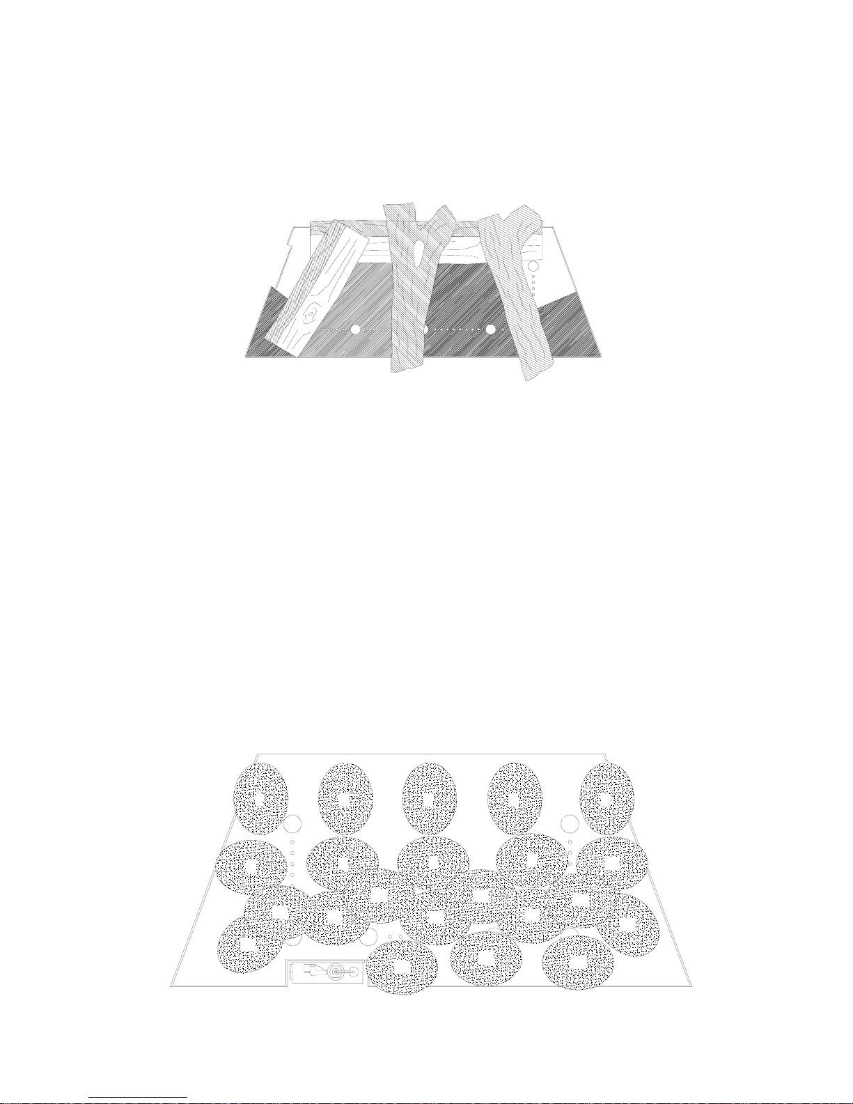
8.1 Log Arrangement
Parts – 4 ceramic logs, 1 bag of embers. Montana + Celsius*
* for Celsius there are 12 LOGS – layout of 3 MONTANA.
Lay the logs as shown in the diagram above. Start by placing the Large log in the
centre of the Burner Top, locating the log centrally and symmetrical with the holes in
the Top Plate. Next place the three small logs around the larger log, as shown above.
Finally open the bag of Embers and scatter it over the top of the burner between the
logs as shown in the highlighted area in the diagram above.
8.2 Pebble Arrangement
Parts – 22 ceramic pebbles for Montana + Celsius*
* for Celsius there are 66 Pebbles – layout of 3 MONTANA.
Place the Ceramic Mat on the Burner Top, aligning the holes with those on top of the
burner. Place 5 Pebbles along the rear of the burner. Place another row of 5 Pebbles in
front of these. Now place 3 Pebbles in front of the centre 3 pebbles of the previous
row. Next, place 3 pebbles to the R/H side of the Pilot shield and forward of the
previous 3 pebbles. Place 1 pebble in both of the front corners of the burner. The
remaining 4 Pebbles are nested on top of the 2
nd
and 3rd row of pebbles. This can all
be seen in the figure below.
13
9
17
19
6
1
11
7
14
20
12
8
15
21
23 4
22
16
18
10
5
Page 9

9
9. TEST FOR SPILLAGE
A spillage test MUST be made before the installed Fire is left with the customer.
Carry out the test by first closing all doors and windows in the room containing the Fire.
Ensure that the Fire is burning at full rate for a minimum of 5 minutes.
With the appliance still lit apply a smoke match or smoke puffer into the flue or gas fire
canopy, and ensure that all smoke is drawn into the flue.
If there is a fan in a nearby room the spillage test must be repeated with the fan running
and all connecting doors between the fire and fan left open.
If there are still problems the chimney/flue may require attention. Disconnect the Fire
and seek expert advice.
10. OPERATING THE FIRE
IT IS VERY IMPORTANT TO READ THESE INSTRUCTIONS
THOROUGHLY BEFORE LIGHTING THE FIRE.
PLEASE EXPLAIN TO THE CUSTOMER THESE LIGHTING
AND EXTINGUISHING PROCEDURES, AND ENSURE THAT
THE USER IS WARNED NOT TO DISTURB THE FUEL BED, OR
CONTAMINATE IT WITH ANY OTHER ITEMS.
This appliance operates with a traditional permanent pilot light.
The pilot light is located at the rear left of the burner and is visible past the logs.
If the Flame Supervision Device Actuating Flame (the pilot light) is extinguished either
intentionally or not, no attempt should be made to relight until 10 minutes have elapsed.
Important: Immediately after lighting, the Fire must be left on maximum setting for ten
minutes in order to warm up the chimney.
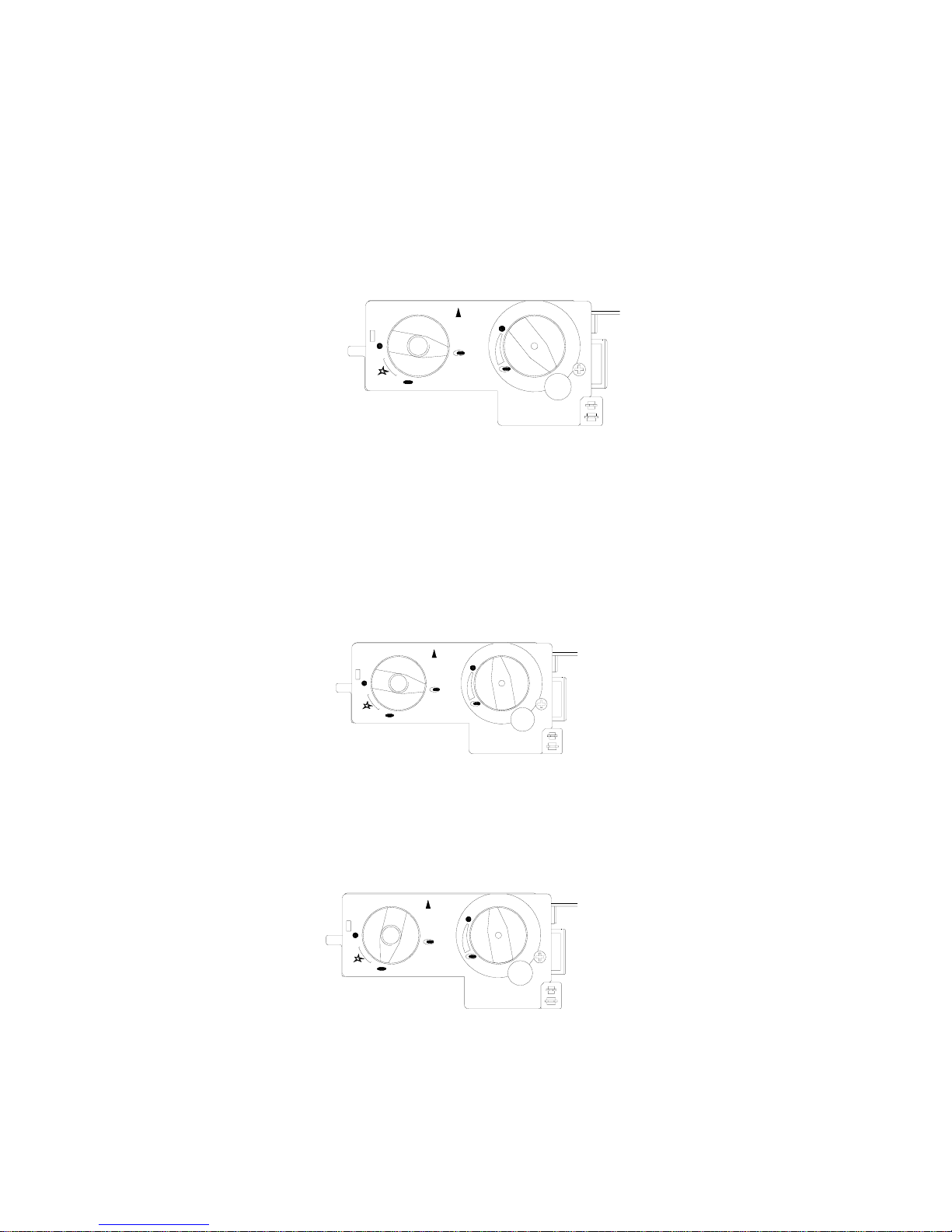
10.1 MANUAL CONTROL
i) Igniting the Pilot Light
1. Turn the Left hand knob slightly anti-clockwise towards the ignition position until
reaching stop, depress and hold for five seconds (only pilot gas flows).
Page 10
10
2. Whilst still depressed, turn further in an anti-clockwise direction to activate the piezo.
If the pilot does not light, steps 1 and 2 can be repeated immediately.
3. Continue to keep the knob depressed for a further 10 seconds, after the pilot has been
lit.
4. Upon releasing the knob, the permanent pilot will remain lit, if not return to 1.
ii) Running the fire at high output
1. Ignite permanent pilot as shown in 14.2 (i).
2. Turn the left-hand control knob anti-clockwise to the setting, which shows the larger
flame.
3. Turn the right-hand control knob anti-clockwise to the highest setting (large flame).
4. The fire is now burning at it’s highest operating output.
iii) Running the fire at low setting
1. Ignite permanent pilot and run fire at “HIGH” setting for a minimum of 10
minutes as shown in 14.2 (ii).
2. With the right-hand control knob at the highest setting, rotate in a clock-wise
direction to the lowest setting (filled circle).
3. The fire is now burning at its lowest operating output.
iv) Extinguishing the fire back to permanent pilot setting
1. From any heat setting, turn the left-hand knob in a clockwise direction to the “PILOT”
position (a smaller flame is shown).
v) Extinguishing the fire fully
1. From any heat setting, turn to “PILOT” as in 14.2 (iv).
2. Depress the same knob slightly and turn clockwise to “OFF” position (filled circle).
10.2 REMOTE CONTROL
Page 11

11
Operation of the remote control tap is the same as for the manual tap. However in
addition to the manual operation it is possible to regulate the minimum to maximum settings
with the remote handset. In order to do this the remote control box has to first be fitted to the
gas control tap. This is done by attaching the two spade connectors, which need to be fitted
(different sizes to ensure correct connection.) Batteries require to be fitted into both the
handset and remote receivers in accordance with the diagrams.
Pressing the lower button on the handset will reduce the flow of gas to the burner. To
increase the flow, both of the buttons should be depressed together. It is also possible to turn
the main burner all the way down so that it is off, leaving only the pilot ignited.
Extinguishing the fire fully
1. From any heat setting, turn to “PILOT” as in 14.2 (iv).
2. Depress the same knob fully and turn clockwise to “OFF” position (filled circle).
11. TROUBLESHOOTING
1 The gas pilot will not ignite or stay lit?
- Ensure the gas is turned on at the appliance and the meter/cylinder
- Hold in the pilot gas button for at least 20 seconds once the pilot is alight to
ensure the operation of the safety Thermocouple valve
- Ensure that the pilot injector is not obstructed or blocked and is free from any
dust or dirt
- Ensure that the Thermocouple has not been damaged in transit. This is a very
delicate Electro-magnetic device
2 The pilot is not burning or performing correctly?
- Ensure the pilot flame is the correct size for the type of gas. The flame should be
focused on the thermocouple probe, so that it is evenly encircled
- The pilot should have two flames, one directed towards the thermocouple, and
one towards the bed of the fire. The pilot head will have been set correctly in the
factory
3 The main burner does not seem to be burning correctly?
- Ensure adequate gas pressure to the appliance. The pressure can be measured by
unscrewing the pressure test nipple on the tap and applying a suitable pressure
gauge (i.e. a manometer). Ensure adequate volume of gas is being used. Once the
fire is burning on maximum, turn off all other gas appliances in the house and
calculate the fuel being burned from the gas meter
- Make sure that the burner is burning correctly. The flames should be fairly even
across the top of the burner before any logs, pebbles or embers are placed on top
12. SERVICING INSTRUCTIONS
This appliance should be serviced annually.
These instructions are meant to be used in conjunction with the normal servicing practices that
a Corgi authorised installer would use.
1. Remove the Logs and embers carefully and replace any that are damaged or broken.
Page 12

12
2. Clean any deposition of lint off the burner. This can be done with a soft brush, or
vacuum cleaner.
3. Inspect the burner unit.
4. Relay the Fire in line with the instructions “arranging the layout of the Logs”.
5. There should be no need to service the burner. If however this is required, a
competent fitter should check the setting pressure at the nozzle on the gas inlet of the
burner. The correct pressure required is stated on the data information plate.
During servicing the chimney should be checked to ensure that products of combustion are
entering the flue, and that there is no excessive build up of soot. Any soot deposits will
require removal. Any purpose provided ventilation should be free from obstruction
13. SERVICE PARTS
Only the logs, embers, pebbles and gas tap/valve are serviceable. Only spares of the correct
type should be used.
Page 13
13
A
PPENDIX
1
R
EMOTE CONTROL WITH CLIMATE CONTROL
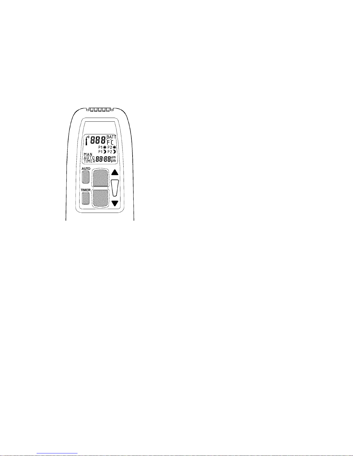
Setting the Display
After connecting the battery or by simultaneously pressing
AUTO
and
TIMER
, the display
flashes. You are in set mode.
From set mode, press
AUTO
to switch from °F (and 12 hour
clock) to °C (and 24 hour clock) or vice versa.
The display will automatically return to manual mode after
some time, but you may immediately return to manual by
depressing the
TIMER
button.
Setting the current Time
After connecting the battery or by simultaneously pressing
AUTO
and
TIMER
, the display flashes. You are in set mode.
From set mode, press (▲) to set the hour and (▼) to set the
minute.
Wait or press
TIMER
to return to “manual“mode.
Programming the Desired Set Temperature
Press
AUTO
until the display flashes.
Press (▲) or (▼) to set the desired temperature.
Wait or press
AUTO
to switch to automatic mode.
A sensor in the transmitter measures the room temperature. The controller compares the
room temperature with the set temperature and sends a signal to the receiver to turn the gas
valve motor, which adjusts the flame height accordingly.
Programming the Timer
Press TIMER until P1
flashes (period 1, heating cycle on).
Set the time for the beginning of the first heating period by pressing (▲) for hour and (▼) for
minute.
Press
TIMER
again,
P1H
appears.
Set the time for the end of the first heating period.
Press TIMER again to set the second heating period P2 (heat on) and P2H (heat off).
Store both heating periods by pressing
TIMER
again.
If only one heating period is desired, program the same time for P2 and
P2H
.
Manual Mode for Manual Flame Height Adjustment
(MAN in display)
Press (▲) to turn on the fire (main burner) or to increase flame height
Press (▼) to decrease flame or to turn down to pilot.
To incrementally increase or decrease the flame height lightly tap either the (▲) or (▼)
button.
The “send“ symbol appears in the upper left corner of the display when either button is
depressed.
The LED of the receiver flashes when knob B of the valve reaches its end stops.
Automatic Mode for Temperature Control
(AUTO in display)
Briefly press AUTO. The set temperature will appear briefly before the display reverts to the
room temperature.
Page 14
14
Timer Mode (TIMER in display)
During heating periods P1 and
P2
H
, the temperature is controlled in the same manner as
in automatic mode.
When the timer program turns to
H
(heating cycle off), the motor will turn the valve to pilot and
there is no temperature control. This minimizes battery consumption.
You may press
AUTO
to verify the set-temperature and then press
TIMER
to return to timer
mode.
You may press either the (▲) or (▼) button from any mode for manual override.
To prolong battery life, we recommend switching the transmitter to manual mode and turning
the fire to pilot with the (▲) button before turning the appliance off. If the transmitter is left in
automatic or timer mode, the batteries will continue to be used when the appliance is off.
A
PPENDIX
2
R
EMOTE CONTROL ELECTRONIC IGNITION SYSTEM
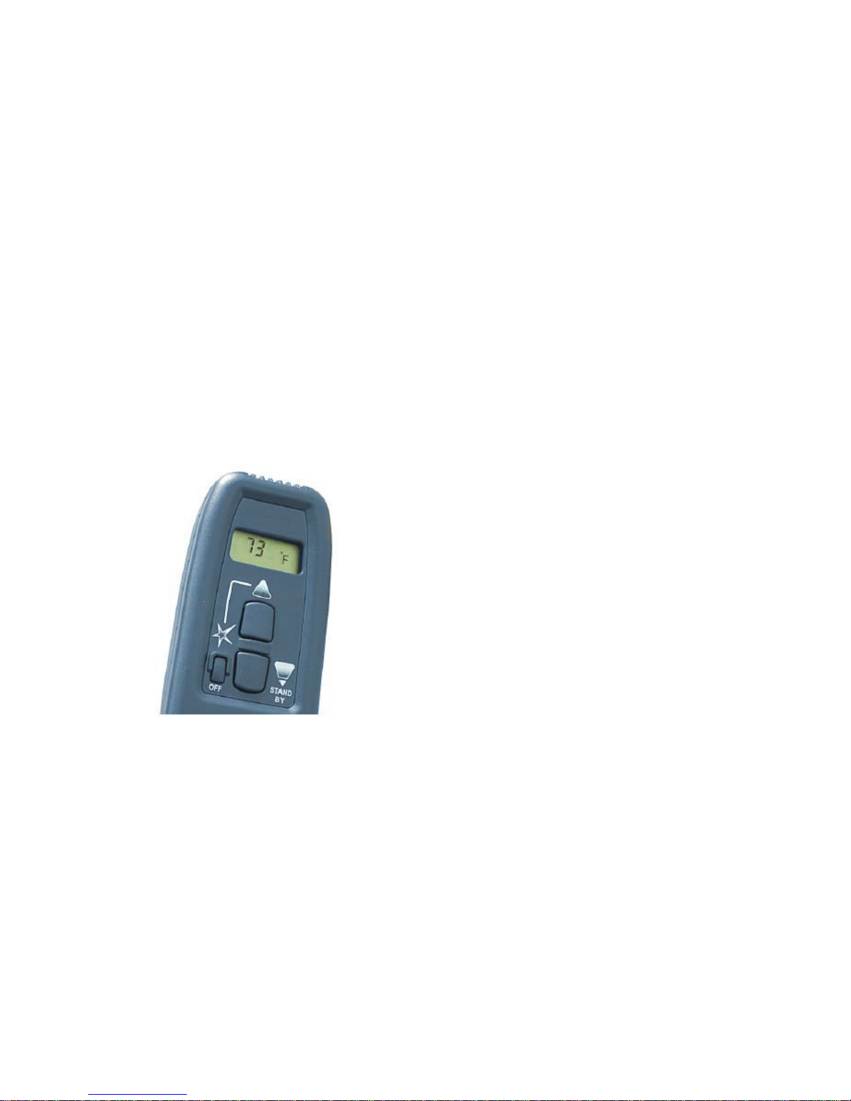
Igniting the Appliance.
Simultaneously press the “(Spark) OFF” and “▲ ” buttons
of the receiver for ignition.
An acoustic signal indicates that the start sequence has
begun.
The electronic system then checks that the main gas is
flowing and ignites the main burner; this may take up to 20
seconds.
(NOTE: During start-up, override knob cannot be in
Manual position.)
Adjusting the Heat Setting
You are now able to use the remote control. To increase
the flame, the top button (▲) should be depressed.
Pressing the lower button (▼) on the handset will reduce
the flame.
It is also possible to turn the main burner all the way down
so that it is effectively off, leaving only the pilot ignited.
Extinguishing the Appliance Fully
From any heat setting, press the “(Spark) OFF” button for a few seconds. This will cause the
burner to fully extinguish.
The system has a safety interlock which will not allow the Ignition until the Interlock rests (this
may take a few minutes).
Page 15
15
Manual Override
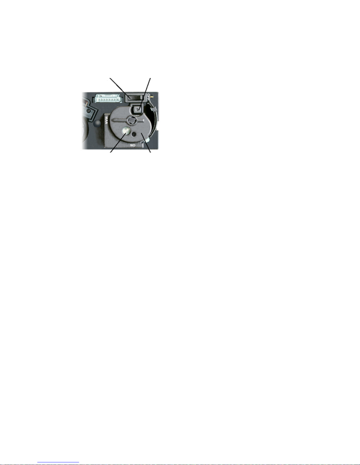
The system has a “Manual Override” feature
that allows manual operation without battery
power. For manual operation, turn the override
knob to the “
MAN
” position. There is an
opening that allows access to the magnet
stem, this should be pushed in to allow gas to
pass to the pilot. This stem must be held in
whilst the Piezo igniter is depressed to spark
the Pilot. The stem must be held in for a
further 15 seconds until the pilot light
establishes. If the Pilot does not hold when the
stem is released, repeat the process.
When the pilot is established, the “Override”
Knob may be turned to the “ON” position.
Control of the gas is then possible using the
second control.
To turn the appliance off using the manual
override, flip the “ON-OFF” switch.
“ON-OFF” switch Piezo Igniter
Magnet Stem Override knob
 Loading...