

ORTAL Stand Alone 40 TS, Clear RS Tunnel, Clear LS Tunnel, Clear TS Tunnel, Clear 4070RS Tunnel Installation & Operation Manual
...
ORTAL Heating Solutions Ltd.
INSTALLATION & OPERATION MANUAL
The ORTAL direct vent (and ORTAL power vent with separate manual) gas appliances have
been tested and approved by CSA for safet y and eff ic i e nc y for use with either Natural Gas (NG)
or Propa ne (LPG).
Standard references:
ANSI Z21.88-2009 - Vented G as Fireplace Heaters
CLASS 2901 84 – DOMESTIC HEATERS (GAS) Vented Fireplace – Cert i f ied t o US St andard
CLASS 2901 04 – DOMESTIC HEATERS (GAS) Vented Fireplace
Pictured Above: ORTAL’s Clear 110 TS
1

ORTAL HEATING SOLUTIONS FIREPLACE MANUAL
TABLE OF CONTENTS
1. Introduction to Ortal and Company Profile 4
2. Fireplace Saf ety Information and Warnings 5
3. Product Listing 7
a. Certifications and C odes 7, cover
b. Product List: Models and Burners 8
Note: Clear
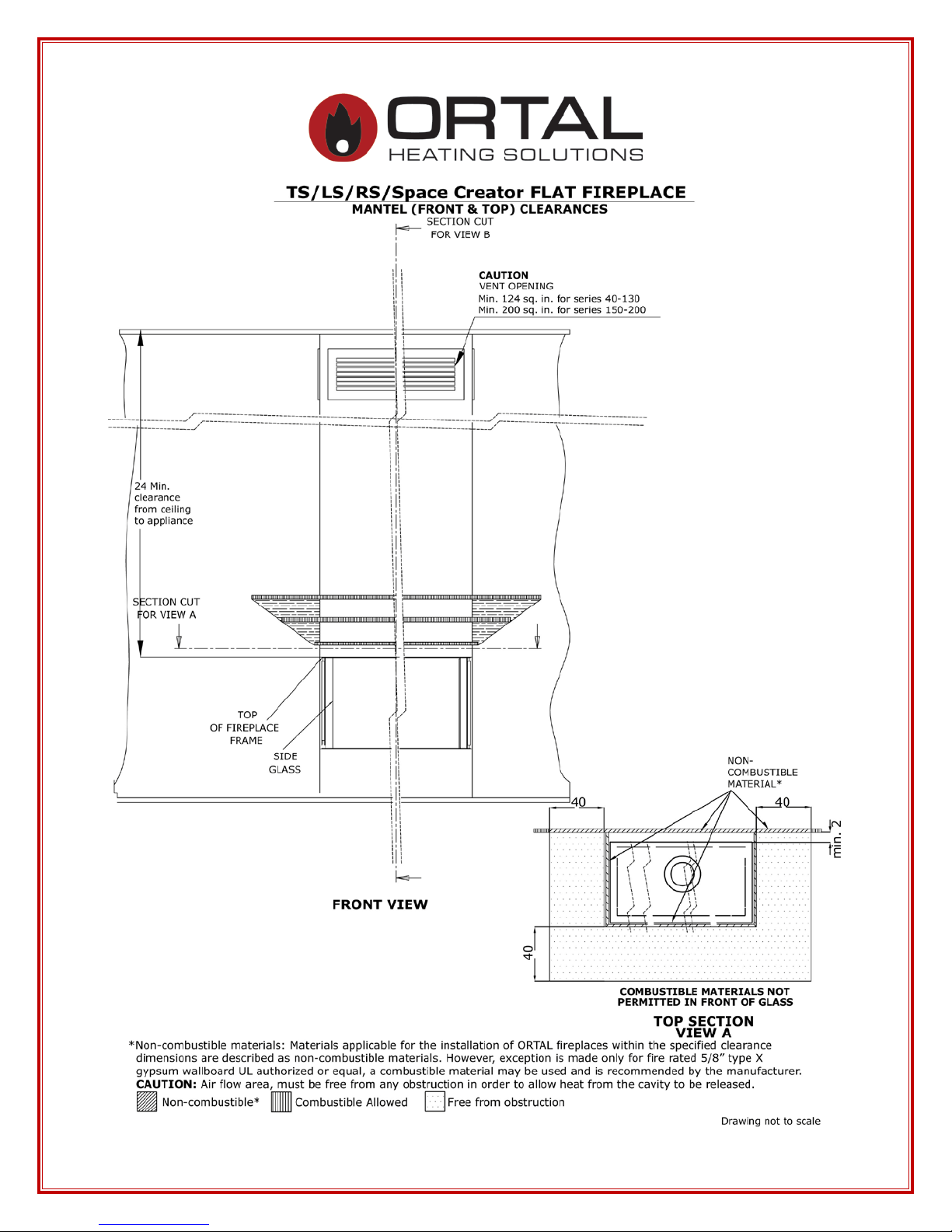
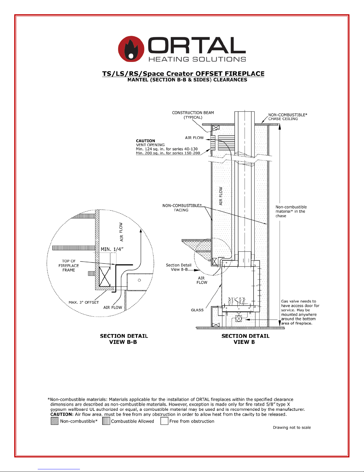
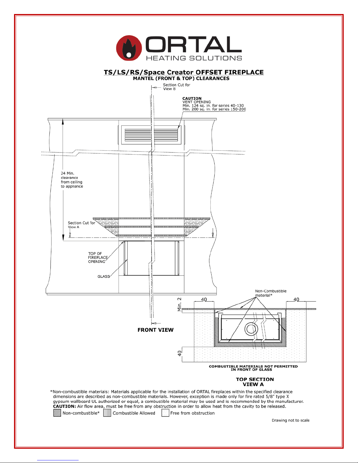
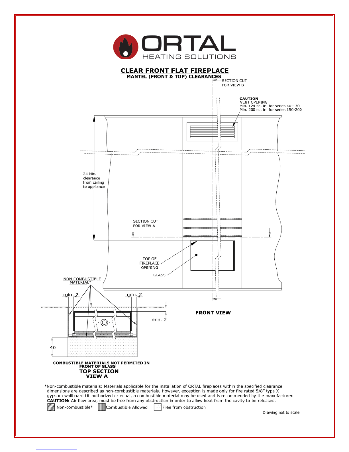
4. Fireplace Clearances 9
a. S tanda rd cl eara nces 9
Note: TS/LS/RS/SC (pages 10 to 13), Front (pages 14 to 17), Tunnel (page 21)
b. Mantel detail 10
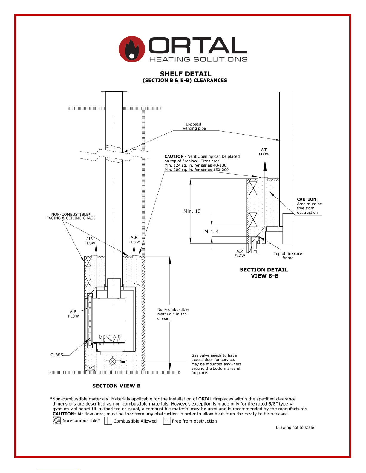
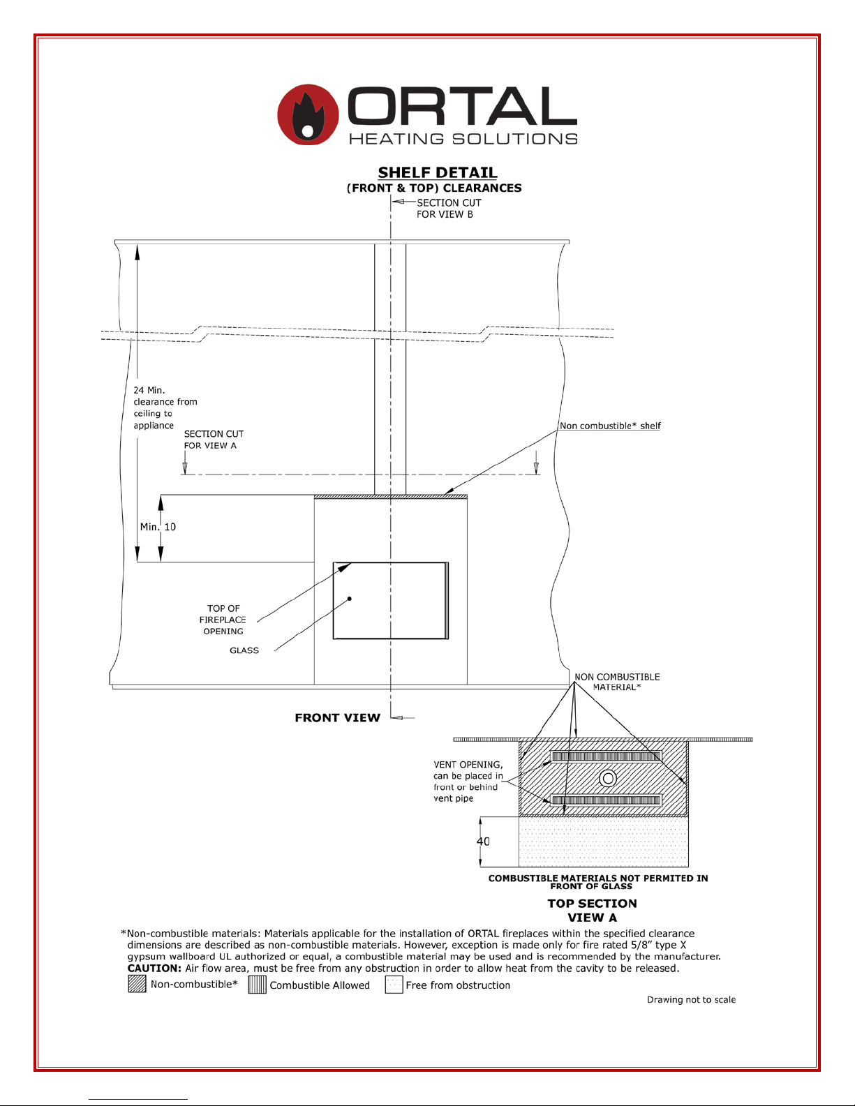
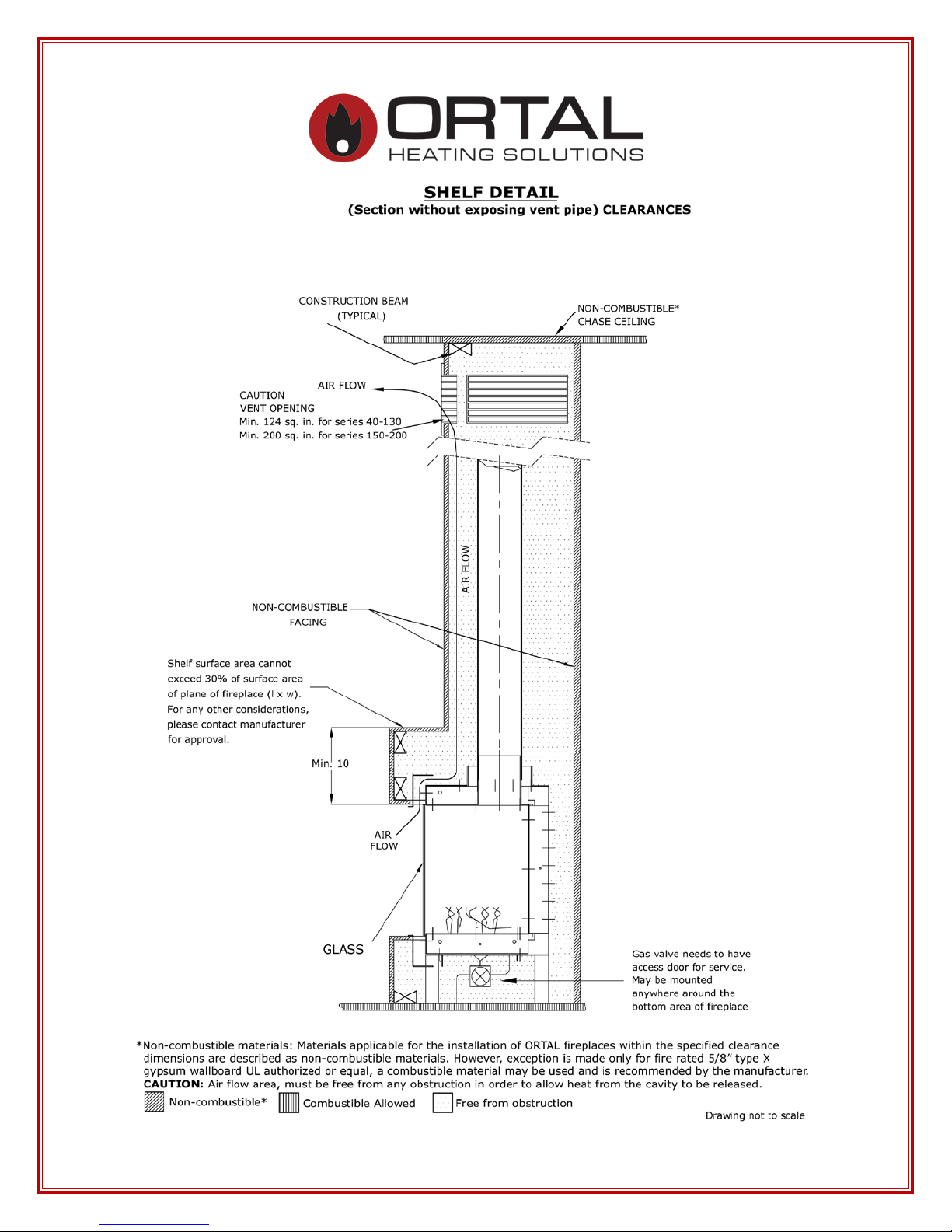
c. Shelf detail 22
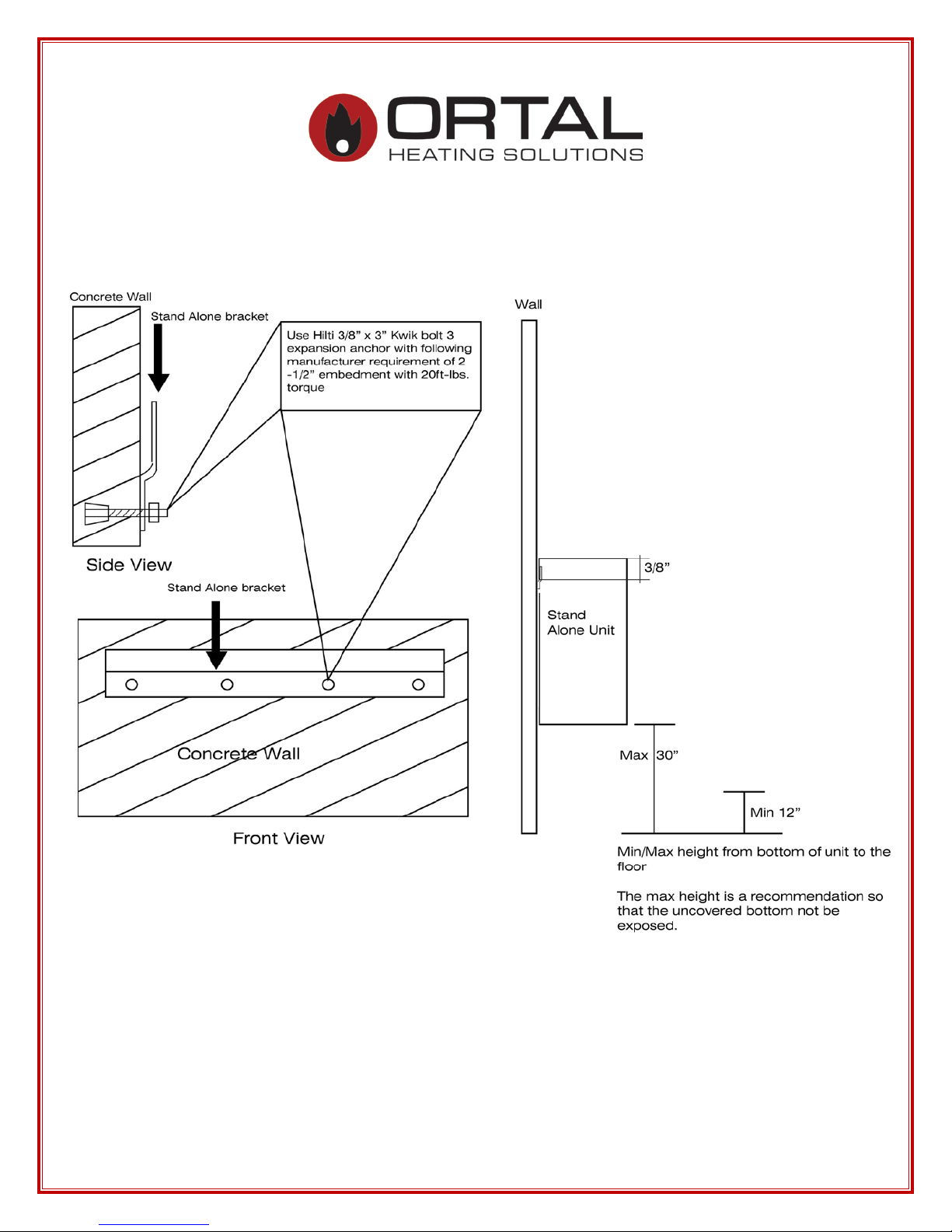
d. Stand Alone mounting detail 25 (through 33)
70 Front/RS/LS/TS/SA will now be termed as Clear 75
Front/RS/LS/TS/SA
Note: SA75 (pages 28 to 29), SA110 (pages 30 to 31), SA150 (pages 32 to 33)
e. Cold Wall Technology 34
f. TV abo ve firep lace install detail 37
Note: This is for all models/series although the drawing mentions Clear Front
g. Double glass air intake detail 43
h. Wall support sample detail 46
5. Gas Informati on 47
a. Gas type 47
b. Routing of Gas Line 47
c. Gas Pressure and Power Output 48
Note: Burner 30 (Series 40) page 48, Burner 45 (Series 75) page 49, Burner 100 (Series
110-130) page 50, Burner 135 (Series 150-170) page 51, Burner 160 (Series 200) page 52
d. Gas Control Ass e mblies & Components 55
e. Gas Conve rsion 57
f. Burner 57
g. Orifices Tabl e 58
h. Pilot & Thermocoupl e M aintenance 59
6. Install Vent System (also see Appendix A) 60
a. Restr ic tors & Vent Arrange m e nt 60
2

b. Schematic Drawing 62
c. Restrictor table per burners 63
d. Vent Installation 68
e. Vent Clearances 68
f. Vent Maintenance 68
g. Vent termination 69
7. Fireplace Installatio n Instr uc tions and Checklist 70
a. Loc ati ng Your Gas Fire Place 71
b. Handling the Glass (also see Appendix C) 72
c. Int erior Desi gn Medi a 74
d. I n terior Refl ective Panel 75
e. Insulation for Cold C limate 76
8. Opera ti ng Inst ruc tions and War ni ngs 77
a. Mertik Electronics Control System (also see Appendix B) 77
9. General M aintenance Instr uc tion 78
a. General Maintenance 78
b. Ortal Factory Recommended Service 80
c. Service Log 82
10. Manufacturer and Supplier Contact Informatio n 83
11. Sample Product Ce r tificatio n Labels 84
12. Lis t of A ppend ic es 89
Appendix A – M&G DuraVent , Direct Vent Pro with vent termination
Appendix B – Mertik Maxitrol
i. Installation Instructions
ii. Mertik Maxitrol Operating Instr uction s
iii. Mertik Maxit rol Wall S w itch
iv. Mertik Maxitrol Smart Home Connections
v. Mertik Maxitrol Troubleshooting
Appendix C – 500° RTV High Heat Silicon Sealant
Appendix D – Double burner units, special notes
Appendix E – ORTAL USA Trouble Shooting Guide
NOTE: Diagrams and i llus trations are no t to sc ale. (Clearance diagrams).
All fireplace drawings with dimensions are available on our website under
Products>Downloads>Diagram
3

INTRODUCTION
Company P rof ile
Welcome to ORTAL and ORTAL USA.
ORTAL, providing heating solutions for over 25 years, is well k nown for its wide
selection of modern gas fireplaces, produced with close attention to detail, finishing,
heating efficiency and quality. ORTAL’s products combine traditional and modern
design with the technology innovation that ensures a gree n product with high ef ficiency
ratings. Our advanced t echnology produces eye catching fires that ar e safe, beautiful and
economical. Our product sophist ication allows ins ta lla tio n in mor e locations inside the
home.
ORTAL offers the largest selection of modern gas fireplaces in North America availa ble
in an array of sizes to suit design and architectural needs integrat ing heat into t he
aesthetics of life. ORT AL also welcomes clients’ visions for custo m-made fireplaces for
special requirements, sizes and uses. Our high quality fireplaces are CSA and CE
certifie d. ORTAL fireplaces are a vai la ble in North Amer ica n t hrough ORTAL USA
approved dealers who ea c h have a s trong co mmitment to offer the best installa tio n and
service.
Green Statement: ORT AL offers a green, envir onmentally friendl y heat ing
solution for the modern era. With ORTAL’s high e f ficiency ratings and
contemporary designs, you don’t have to sacrifice for m for function. The
unique design maxim izes the firepla ce’s radiant heat. Additional efficient components
include ORTAL’s use o f direct vent t echno log y, elect ronic ignition (instead of a standing
pilot) and low maintenance requirements.
We appreciate you choosing ORTAL for your firep lace needs.
Tha nk yo u ,
Ortal and Ortal USA
4
WARNING
SAVE THESE INSTRUCTIONS
Make yourself fully aware of all the following instructions and the many features of the
OWNER: Keep this manual for future reference.
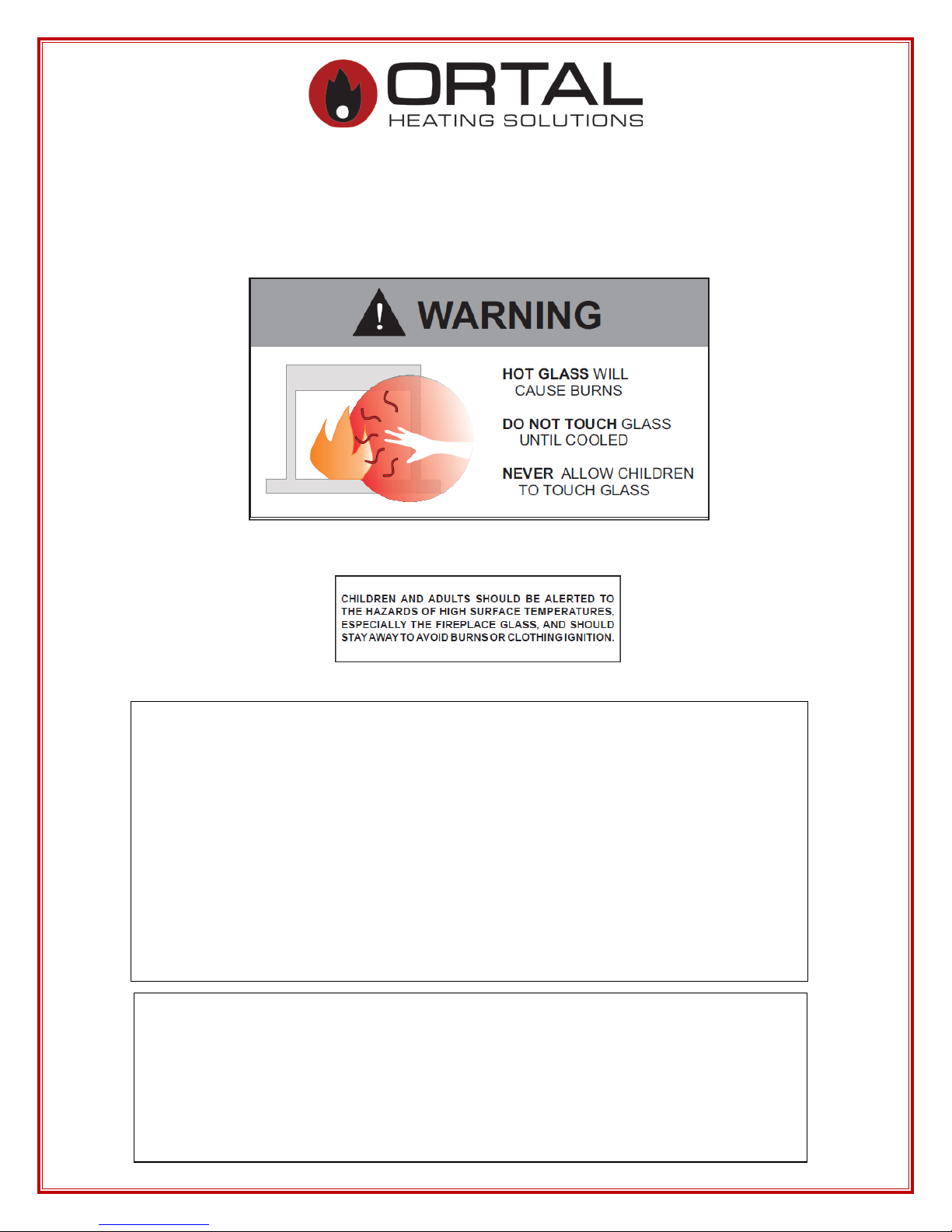
FIREPLACE SAFETY INFORMATION
and WARNINGS
:
The direct vent system applia nce must be installe d as an O EM instal lation in ma nufac tur e d
homes (USA only) or an aftermarket permane ntly located, or a mob ile home, where not
prohibited by local codes and must be i nsta l led in accordance with
Manufac tur er's instr uction s and t he Manufac tur ed Home C onstruct ion a nd Saf ety St andard,
Title 24 C FR, Part 3280, in the Uni ted S tates, or the Standard for I nsta l lati on in Mobile Homes,
CAN/ CSA Z240 MH Series, in Canada.
If the information in these instructions is not followed exactly a f ire or explosion may result
causing property damage , personal inj ury or death.
Do not store or use gasoline or other flammable vapors and liquids in the vicinity of this
appliance.
Ortal direct vent gas fireplace appli an ce .
INSTALLER: Leave this manual with the appliance.
5
WARNING
authorized technician should ONLY remove the glass with the glass vacuum holders
WARNING
70, or the Canadian Electric Code, CSA C22.1.
WARNING
WARNING
The glass must ONLY be removed by an authorized &/or qualified installer. The
supplied by the manufacturer. Lower the glass to rest in a safe place. This is to prevent
damage to the glass edges.
Step 1. Prepare a safe place for the glass to rest.
Step 2. Remove the glass using the vacuum holder.
Step 3. The glass can now be rested safel y.
: Glass Handling
: Electri cal Grounding
These Direct Vent appliances must be electrically grounded in accordance with the
local codes or, in the absence of local codes, with National Electric code, ANSI/NFPA
This appliance is only for use with the type of gas indicated on the rating plate. These
appliances are not convertible for use with other gases, unless a certified kit is used
and the conversion is performed by an authorized qualified technician.
Applicable standards are Vented Gas fireplace heaters ANSI Z21.88 / CS A 2.33a and
gas-fire d applianc es for use at high altitu des CAN/C GA 2. 1 7-M91.
: Gas Appliance
: Installation and Service
Inst allation and s ervice must be p erformed b y an authorized qualified installer service age ncy or
gas supplier.
Any alterat ion to the product that c auses soot or carbon t o form and results in damage i s not the
MODELS
responsibility of the manufacturer.
In the case of mode ls supplied with a doo r fit ted i n the fr ame of the hea ter, ONL Y an
All the models referenc e d in this manual are equipped wit h the sa me basic e qui pment
authorized qualif ied installer may open this doo r. T he end user must NO T open t he door, as this
including: f irebox and leg supports , burner, gas valve, gl ass panels, operat i on control,
may be unsafe a nd may result in voiding the ma nufac turer’s warrant y.
special tool s , etc.
ALL the warnings and instructions apply t o A LL the models.
6

PRODUCT LISTING
Certifications and Codes
The a ppliance has be e n certifi e d for use wit h either natur al gas (NG) or pr opane gas (LP), and
NOT for use with solid fuels .
These gas fireplace appliances are CSA certified and approved for indoor use and can be
specialized with certain requirements for indoor outdoor use (i.e. tunnel models). For indo or
installation they must be installed maintaining required clearances. Installa tion is recommended
in living spaces such as bedrooms, living rooms, great rooms, etc. The appl iance is no t approved
for closet installation.
The a ppliance must be inst alled acc ording to ORTAL and ORTAL USA requir e me nts in add ition
to a ny loca l c odes that may apply. If none exist then the current CSA installation code must be
followed:
• USA, AN SI Z223.1/NFPA 54
• Canada, CSA B149
The appliance must be properly connected to an M&G Dura Ve nt chi m ney ve nting system. Refer
to the specific appliance to determine vent size and pathway requirements.
1. Consult the author ity having j urisdiction to determ ine the need for a pe rmit
PRIOR to starting the installation.
2. It is the responsibility of the installer to ensure that this fireplace is installed
in compliance with the manufacturer’s instructions and all the applicable
codes.
3. Before starting, take careful note of ALL the WARNINGS i n this manual.
7
Burner
Models
Chimney size
• C lear 40 / RS/LS/TS/ Tunnel,
• Cl ear 150 / RS/LS/TS/Tunnel,
C lea r 17 0/ RS/LS/TS/ Tunnel
• Clear 200, Clear 200RS/LS/TS/Tunnel, Space
Product List: Models and Burners
Bur ne rs and venting for m odels can be seen i n the table be low. Adaptors are not requ i red.
30
(S eries 40)
45
(S eries 70 &
80)
100
(Series 110,
120 & 130)
• Stand A lone 40 TS
• C lear 40 70/RS/LS/TS/Tunnel
• C lear 40 90H/RS/LS/TS/Tunnel
• Small Square, Class ic Corner, Mode rn C orner
• Clear 60x80/ Tunnel
• Clear 75/RS/LS/TS, St and Alone 75/TS/Hood
• S pace Creator 75
• Clear 75H TS, Clear 7565/Tunnel
• C lear 80 /RS/LS/TS,
• Clear 8070H/RS/LS/TS
• Classic F 75/80
• 4 Glass Island
• Clear 110, Clear 110 RS/LS/TS/Tunnel
• Stand A lone 110
• Clear 110 H/ Tunnel
• C lear 13 0/RS/LS/TS/Tunnel/Top
• Island 130
• Spac e Creat or 12 0/Mini/Medium
4x6
4x6
5x8
135
(Series 150
& 170)
160
(Series 200)
Two
Burners
• Space Creator 150
• Stand A lone 150
•
Creator 200
• Clear 20070H/RS/LS/TS
• C lear 25 0/RS/LS/TS/Tunnel
• C lear 25 0/RS/LS/TS/ Tunnel
• C lear 35 0/ RS/LS/TS/ Tunnel
• C lear 40 0/ RS/LS/TS/ Tunnel
• 4 G l ass 2 burner s
Refer to Appendix D for specific information relating to
these Two Burner models.
5x8
5x8
5x8
8

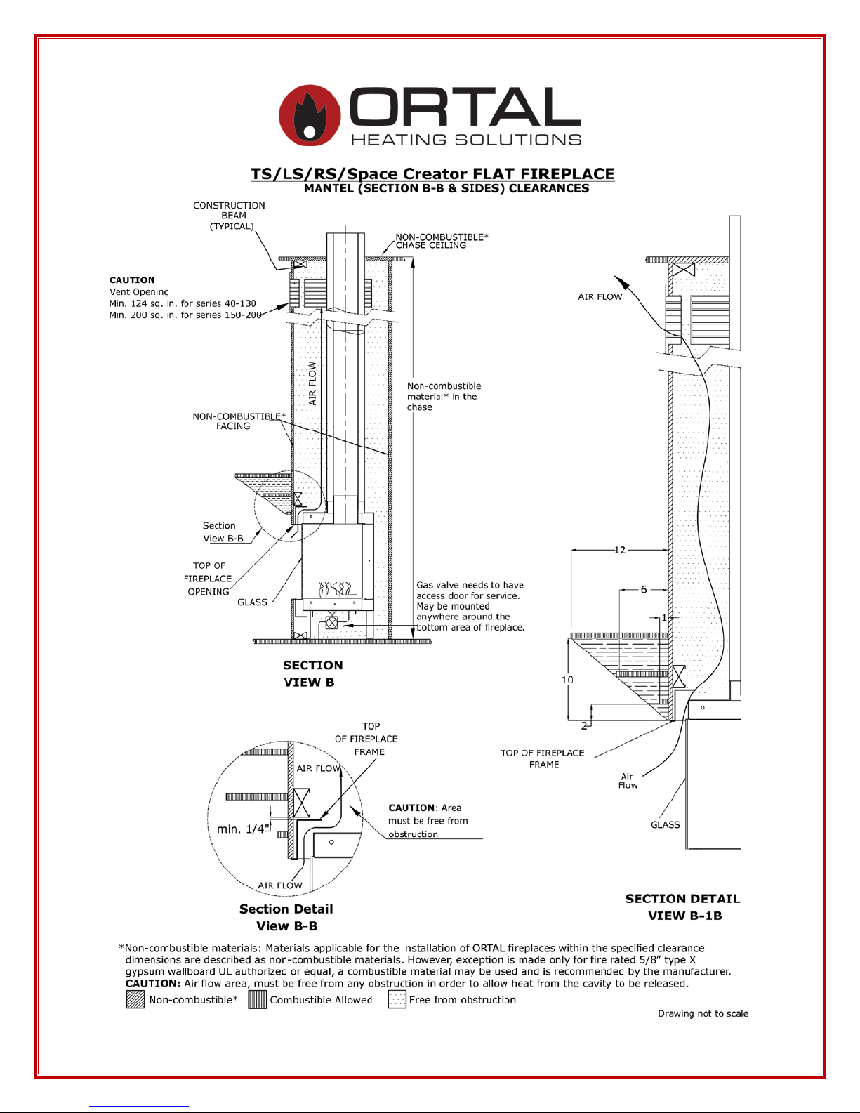
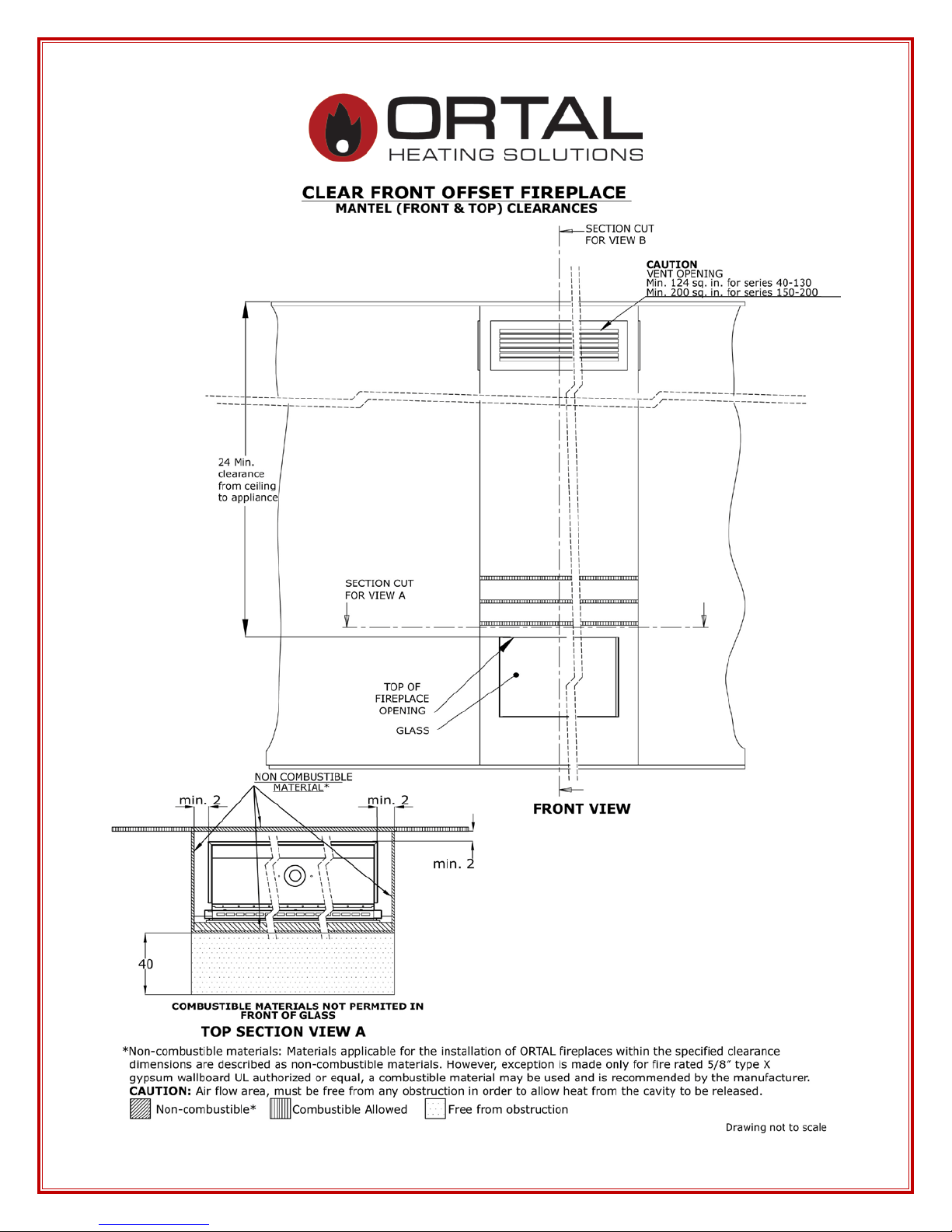
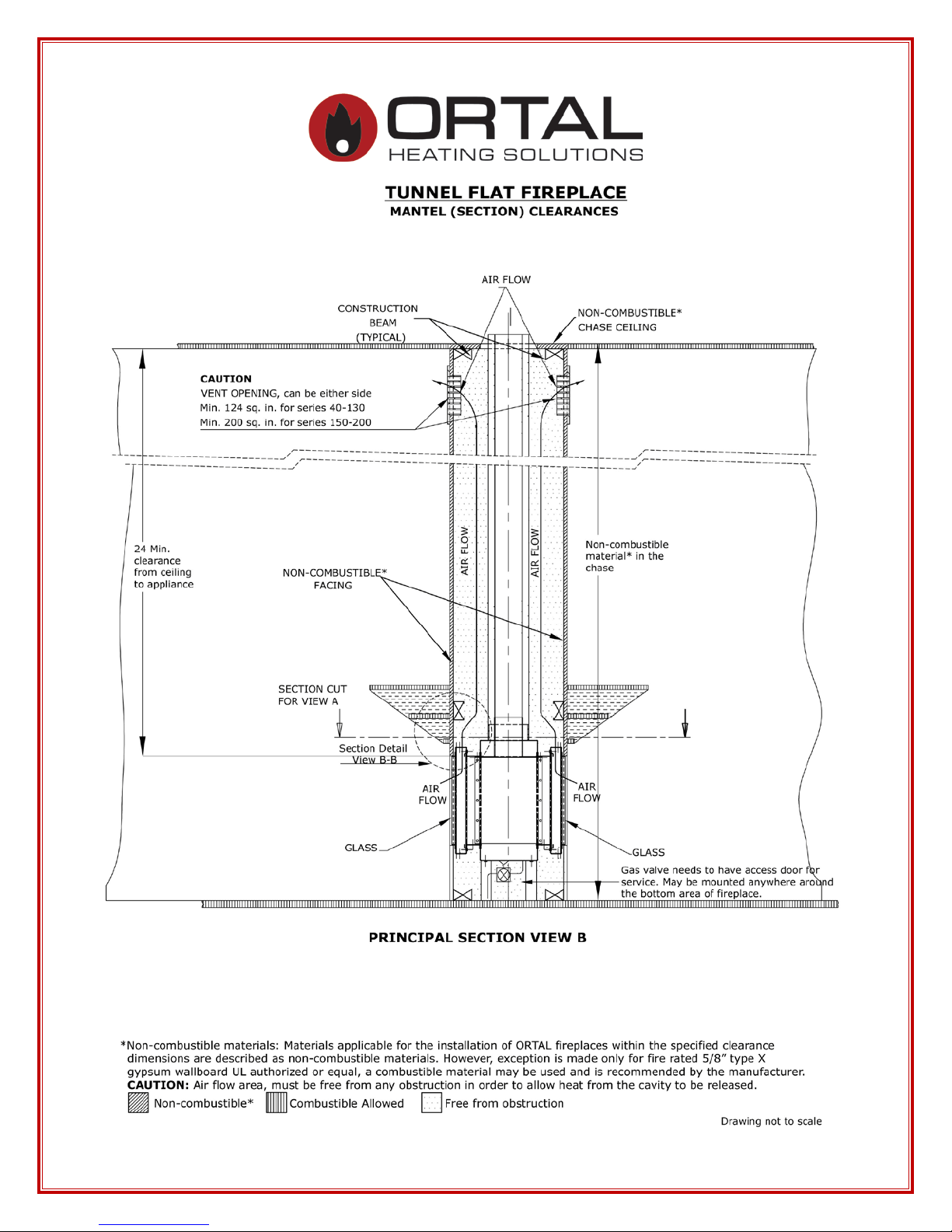
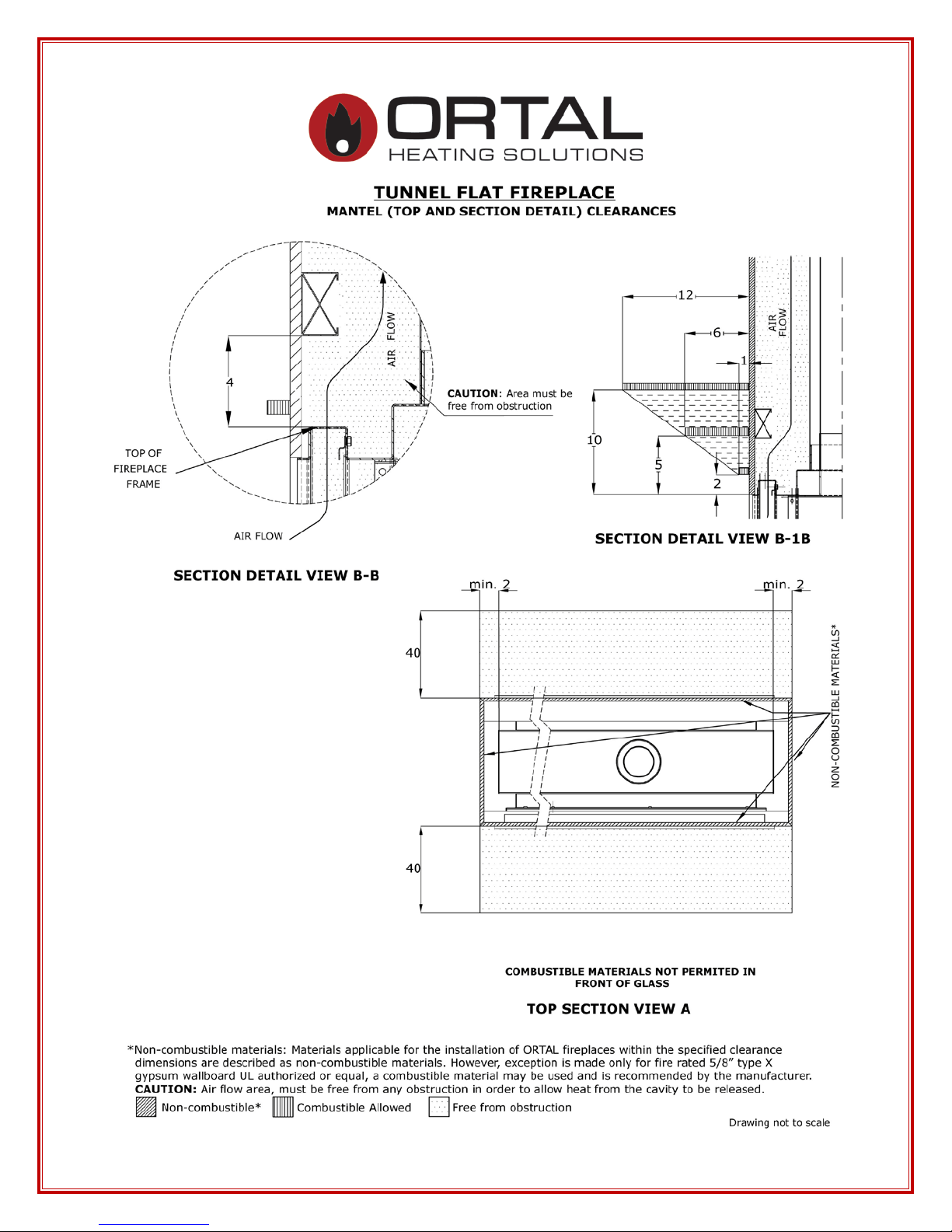
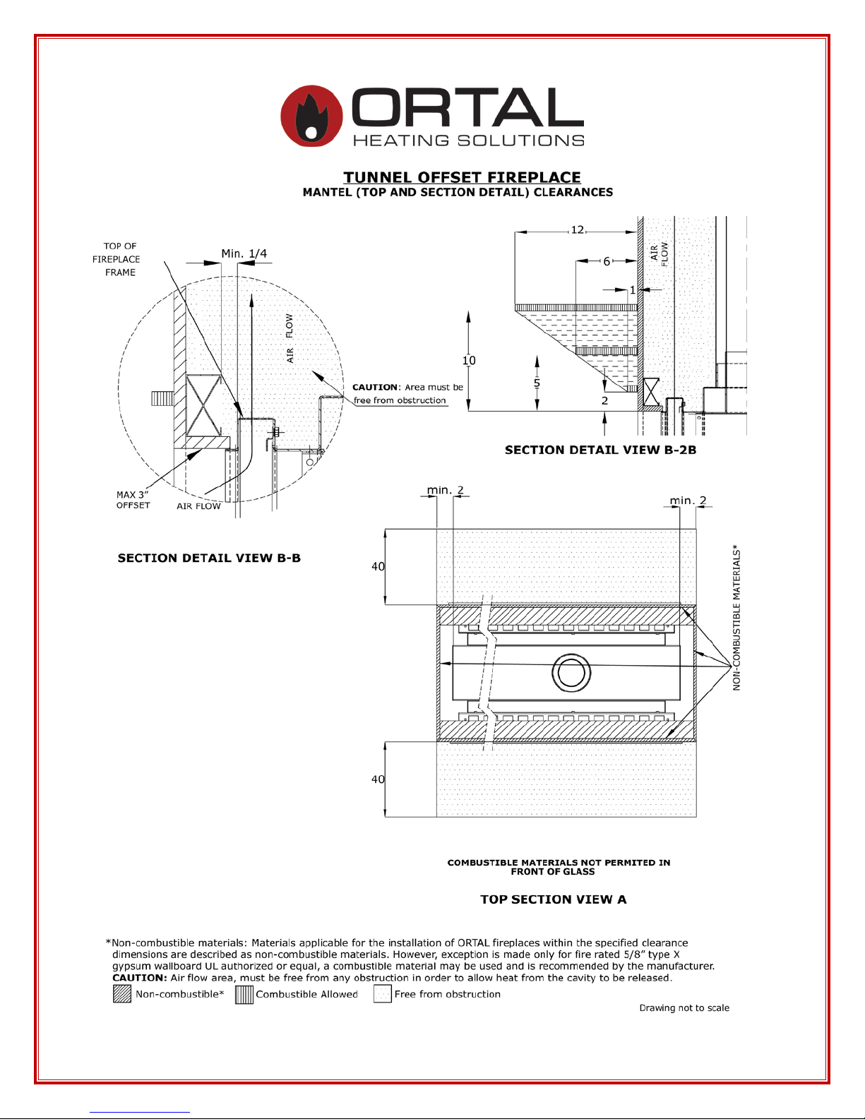
FIREPLACE CLEARANCES
Minimum Clearances to Combustible Materials
Appliance and Vent Clearance s
The appliance is appr oved wit h maintained min imum clearance t o combustible mat erials
as s hown in the diagrams provided.
Non-combus t ible mat er ials , suc h a s sur ro unds a nd ot he r appl ia nc e t rim, may be ins t alle d
on the appliance face so long as it maintains the minimum clearances between the
appliance and the non-combustible material. Surrounding material is not allowed to
transfer we ight to t he unit or be conne cted in any w ay to the unit . The y must not co ver
any portion of the removable glass panel or the control compart ment.
The minimum clearances (a ir space) to combustible materials must be adhered to. It is of
the greatest importance that the fireplace and vent system be installed onl y in accor dance
with these instructions.
Clearance Diagrams on following pages.
Definitions:
“Flat”: walls sur roun ding f inish in the s ame plane a s the fir eplace.
“Offset”: walls sur roun ding finish in a different plane as t he fireplace a nd t here is 90
degree (usually) between t he p la n of the fireplace and the plane of the wall. Maximum
3” horizontal space bet ween t he t wo planes.
9
10
11
12
13

14
15

16
17
18
19

20
21
22
23
24

Stand Alone 40 TS, 75, 75 TS, 110 & 150
Manufa c turer’s Recommendatio n for Wal l Mount ing
1. Co ncrete Wall
a. Pos ition the unit at the desir e d height a nd mark the wa ll. Unit should have
a minimum 12” and maximum 30” distance from the bottom of the unit to
the floor.
b. Mount the Stand Alone hanging bracket using Hilti 3/8” x 3” Kwik bolt 3
expansion anchors with manufa cturer ’ s requirement of 2-1/2” em be dme nt
and torque to 20ft-lbs.
c. Attach the unit to the mounting bracket.
d. See S ketch 1 for detail.
2. Wood Stud Wall
a. Pos ition the unit at the desir e d height a nd mark the wall. Unit shou ld h ave
a minimum 12” and maximum 30” distance from the bottom of the unit to
the floor
b. Create an opening in the wall big enough to position the 4x8 blocks
bet ween the wood s tuds at the desired height.
c. Repair the ope ning w ith hardy backer boar d.
d. Make sure that the bracket has a minimum 4” extra hardy backer board
materia l ar ound it.
e. Mount bracket with a 3/8” x 4” lag bolts. Follow bracket manufacturer’s
installa tion requirements and the n mount t he unit.
f. See sketch 2 for detail.
Note: All installat ions are to be complet ed per local building codes and safety
requirements. T he above reco mmendation does not take the place of reviewing and
incorporating str uctural requirements set forth by the building engineer, local codes, et c.
25
Concrete Wall Mounting Detail
Sketch 1
26
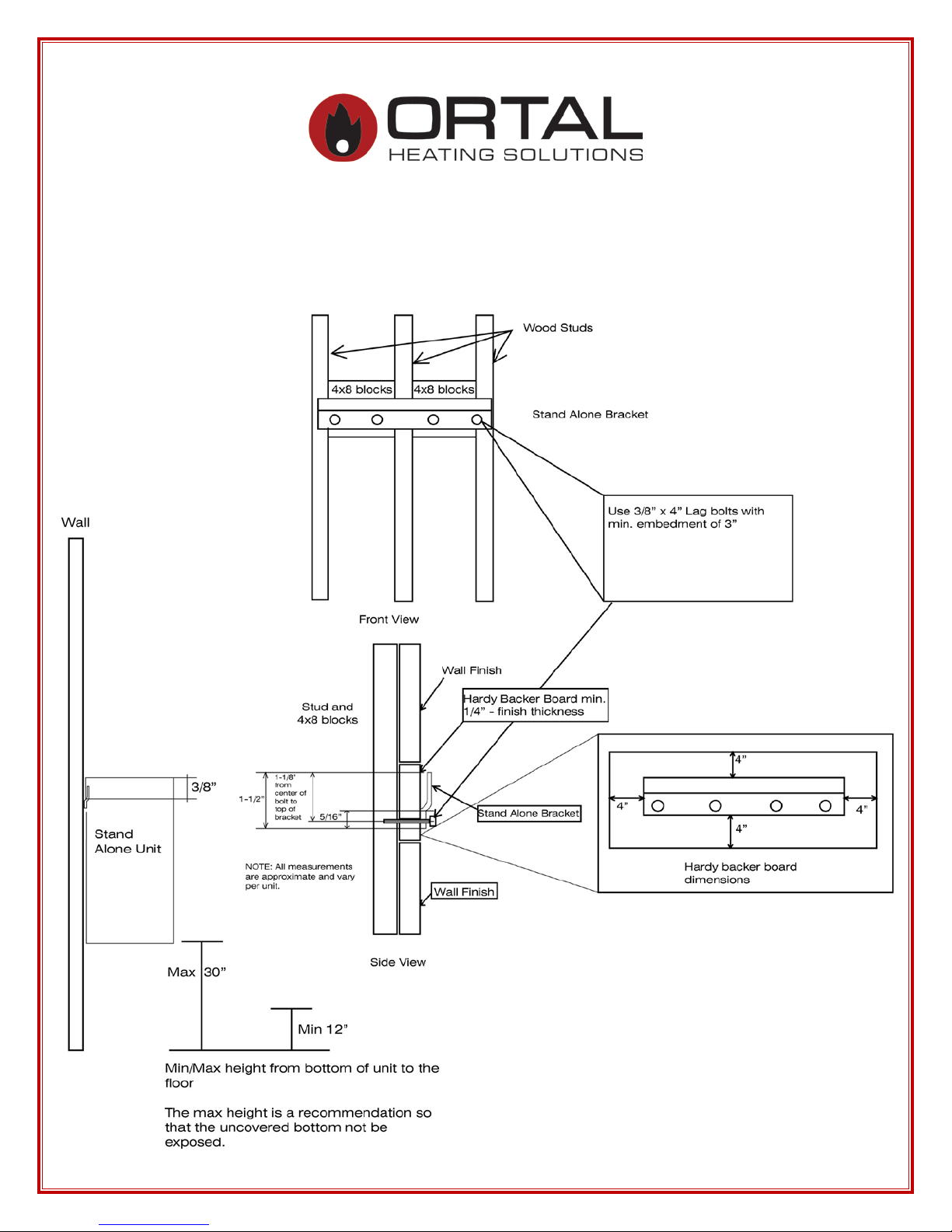
Wood Stud Mounting Detail
Sketch 2
27
Stand Alone 75
28
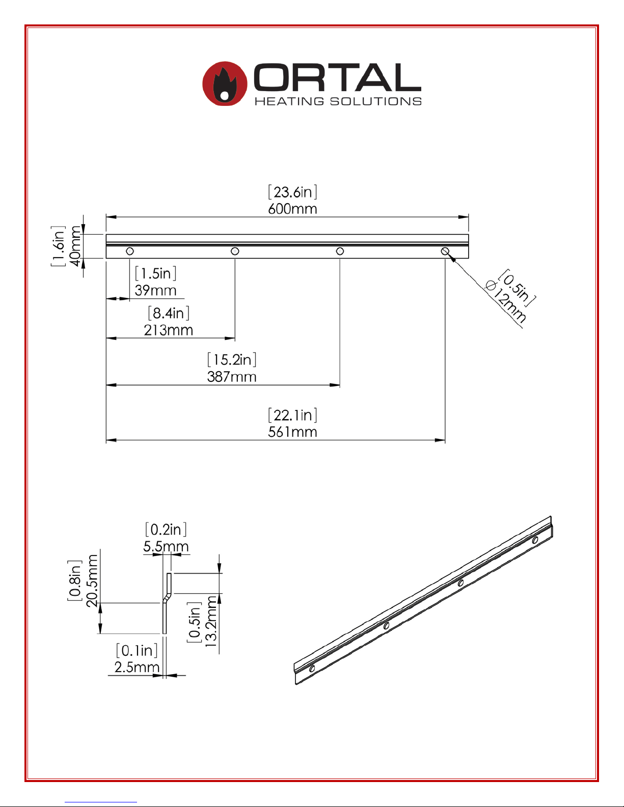
Stand Alone 75 bracket
29

Stand Alone 110
30
 Loading...