

ORTAL Clear 40RS, Clear 40Tunnel, Clear 40TS, Clear 40LS, Stand Alone 40 TS Installation & Operation Manual
...
ORTAL Heating Solutions Ltd.
INSTALLATION & OPERATION MANUAL
The ORTAL direct vent (and ORTAL power vent with separate manual) gas appliances have
been tested and approved by CSA for safety and efficiency for use with either Natural Gas (NG)
or Propane (LPG).
Standard references:
ANSI Z21.88/CSA 2.33-2014- Vented Gas Fireplace Heaters
CLASS 2901 84 – DOMESTIC HEATERS (GAS) Vented Fireplace – Certified to US Standard
CLASS 2901 04 – DOMESTIC HEATERS (GAS) Vented Fireplace
Pictured Above: ORTAL’s Clear 110 TS
Patent Pending for screen barrier glass bracket: USSN 60/040,074
Version: February 24, 2015
1

ORTAL HEATING SOLUTIONS FIREPLACE MANUAL
TABLE OF CONTENTS
1. Introduction to Ortal and Company Profile 4
2. Fireplace Safety Information and Warnings 5
3. Product Listing 8
a. Certifications and Codes 8, cover
b. Product List: Models and Burners 9
Note: Clear
4. Fireplace Clearances 10
a. Standard clearances 10
Note: TS/LS/RS/SC (pages 10 to 13), Front (pages 14 to 17), Tunnel (page 21)
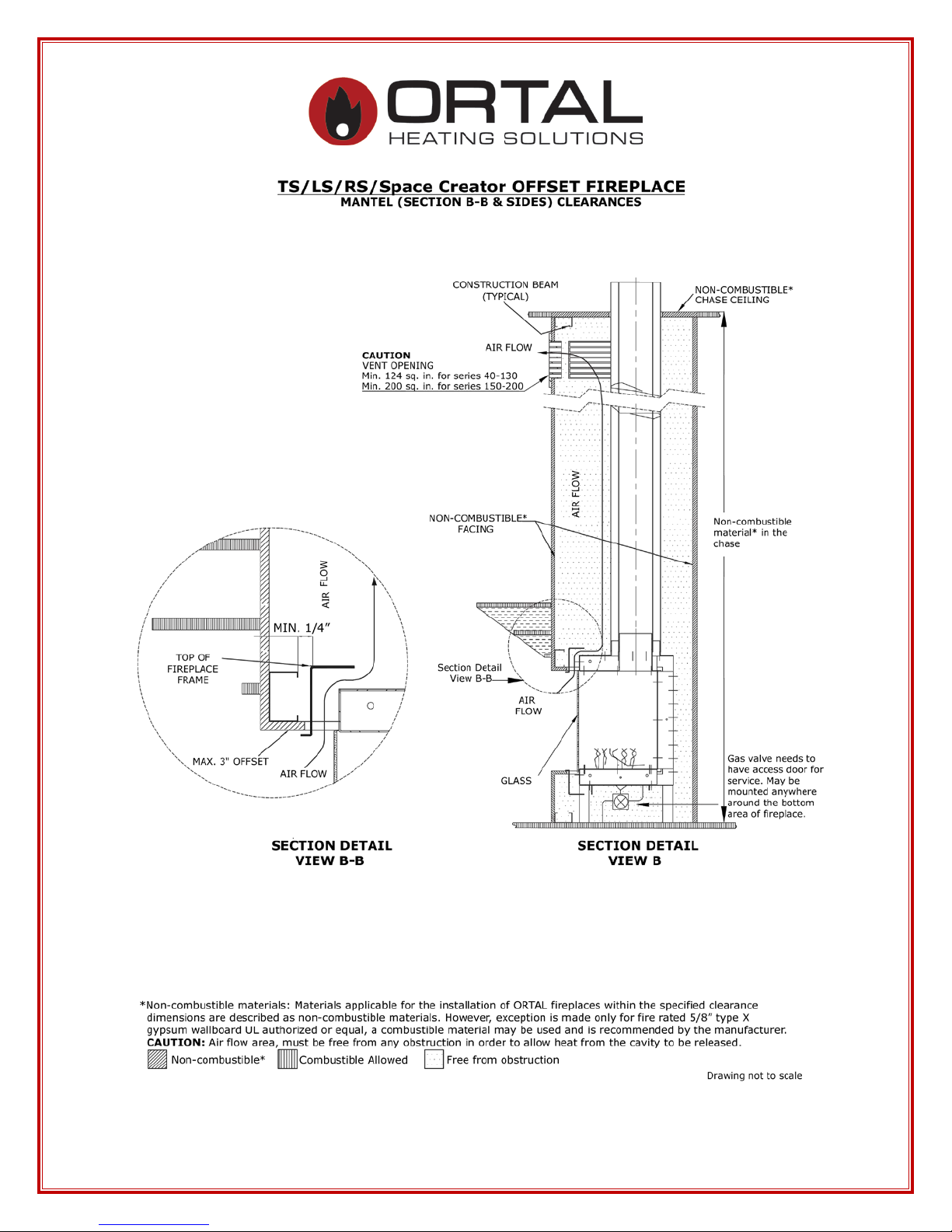
b. Mantel detail 12
c. Shelf detail 24
d. Stand Alone mounting detail 27 (through 37)
70 Front/RS/LS/TS/SA will now be termed as Clear 75
Front/RS/LS/TS/SA
e. Cold Wall Technology 38
f. TV above fireplace install detail 41
Note: This is for all models/series although the drawing mentions Clear Front
g. Double glass air intake detail 47
h. Wall support sample detail 50
5. Gas Information 52
a. Gas type 52
b. Routing of Gas Line 52
c. Gas Pressure and Power Output 53
Note: Burner 30 (Series 40) page 53, Burner 45 (Series 75) page 54, Burner 100
(Series 110-130) page 55, Burner 135 (Series 150-170) page 56, Burner 160 (Series
200) page 57
d. Gas Control Assemblies & Components 60
e. Gas Conversion 63
f. Burner 63
g. Orifices Table 64
h. Pilot & Thermocouple Maintenance 65
6. Install Vent System (see note 1 on page 103) 66
a. Restrictors & Vent Arrangement 66
b. Schematic Drawing 68
2

c. Restrictor table per burners 69
d. Vent Installation 74
e. Vent Clearances 74
f. Vent Maintenance 74
g. Vent termination 75
7. Fireplace Installation Instructions and Checklist 77
a. Locating Your Gas Fire Place 78
b. Handling the Glass (see note 3 on page 103) 79
c. Fireplace Barrier (see Appendix C & D) 81
d. Interior Design Media 83
e. Interior Reflective Panel 84
f. Burning Period 85
g. Insulation for Cold Climate 86
8. Operating Instructions and Warnings 87
a. Mertik Electronics Control System (see note 2 on page 103) 87
9. General Maintenance Instru c tion 88
a. General Maintenance 88
b. Ortal Factory Recommended Service 90
c. Service Log 92
10. Warranty Policy 93
11. Manufacturer and Supplier Contact Information 97
12. Sample Product Certification Labels 98
13. List of Appendices 103
Appendix A – Double burner units, special notes
Appendix B – ORTAL USA Trouble Shooting Guide
Appendix C – Screen Instructions for Front & Tunnel models
Appendix D – Screen Instructions for Mu lt i-sided models
NOTE: Diagrams and illustrations are not to scale. (Clearance diagrams).
All fireplace drawings with dimensions are available on our website under
Products>Downloads>Diagram
3

INTRODUCTION
Company Profile
Welcome to ORTAL and ORTAL USA.
ORTAL, providing heating solutions for over 25 years, is well known for its wide
selection of modern gas fireplaces, produced with close attention to detail, finishing,
heating efficienc y and qual ity. ORTAL’s products combine traditional and modern
design with the technology innovation that ensures a green product with high efficiency
ratings. Our advanced technology produces eye catching fires that are safe, beautiful and
economical. Our product sophistication allows installation in more locations inside the
home.
ORTAL offers the largest selection of modern gas fireplaces in North America available
in an array of sizes to suit design and architectural needs integrating heat into the
aesthetics of life. ORTAL also welcomes clients’ visions for custom-made fireplaces for
special requirements, sizes and uses. Our high quality fireplaces are CSA and CE
certified. ORTAL fireplaces are available in North American through ORTAL USA
approved dealers who each have a strong commitment to offer the best installation and
service.
Green Statement: ORTAL offers a green, environmentally friendly heating
solution for the modern era. With ORTAL’s high efficiency ratings and
contemporary designs, you don’t have to sacrifice form for function. The unique design
maximizes the fireplace’s radiant heat. Additional efficient components include
ORTAL’s use of direct vent technology, electronic ignition (instead of a standing pilot)
and low maintenance requirements.
We appreciate you choosing ORTAL for your fireplace needs.
Thank you,
Ortal and Ortal USA
4

DANGER
Do not store or use gasoline or other flammable vapors and liquids in the vicinity of this
SAVE THESE INSTRUCTIONS
OWNER: Keep this manual for future reference.
FIREPLACE SAFETY INFORMATION & WARNINGS
The direct vent system appliance must be installed as an OEM installation in manufactured
homes (USA only) or an aftermarket permanently located, or a mobile home, where not
prohibited by local codes and must be installed in accordance with
Manufacturer's instructions and the Manufactured Home Construction and Safety Standard,
Title 24 CFR, Part 3280, in the United States, or the Standard for Installation in Mobile Homes,
CAN/CSA Z240 MH Series, in Canada.
If the information in these instructions are not followed exactly a fire or explosion may result
causing property damage, personal injury or loss of life.
appliance.
Make yourself fully aware of all the following instructions and the many features of the
Ortal direct vent gas fireplace appliance.
INSTALLER: Leave this manual with the appliance.
5

WARNING:
WARNING:
WARNING:
to operating.
DANGER:
Do not try to light any appliance.
Do not touch any electrical switch; do not use any phone in your building.
Immediately call you gas supplier from a neighbor’s phone. Follow the gas supplier’ s
instructions.
If you cannot reach your gas supplier, call the fire department.
Due to high temperatures, the appliance should be located out of traffic and away from
furniture and draperies.
Children and adults should be alerted to the hazards of high surface temperature and
should stay away to avoid burns or clothing ignition.
Clothing or other flammable material should not be placed on or near the appliance.
Young children should be carefully supervised when they are in the same room as the
appliance. Toddlers, young children and others may be susceptible to accidental contact burns.
A physical barrier is recommended if there are at risk individuals in the house. To res trict access
to a fireplace or stove, install an adjustable safety gate to keep toddles, young children and other
at risk individuals out of the room and away from hot surfaces.
A barrier designed to reduce the risk of burns from hot viewing glass is provided with this
appliance and shall be installed.
If the barrier becomes damaged, the barrier shall be replaced with the manufacturer’s barrier for
this appliance.
Any safety screen, guard, or barrier removed for servicing the appliance, must be replaced prior
IF YOU SMELL GAS
Fireplace Temperature
Screen Barrier
Glass Handling
The glass must ONLY be removed by an authorized &/or qualified installer. The
authorized technician should ONLY remove the glass with the glass vacuum holders supplied
by the manufacturer. Lower the glass to rest in a safe place. This is to prevent damage to the
glass edges.
Step 1. Prepare a safe place for the glass to rest.
Step 2. Remove the glass using the vacuum holder.
Step 3. The glass can now be rested safely.
6

WARNING:
WARNING:
WARNING
Electrical Grounding
These Direct Vent appliances must be electrically grounded in accordance with the local codes
or, in the absence of local codes, with National Electric code, ANSI/NFPA 70, or the Canadian
Electric Code, CSA C22.1.
This appliance is only for use with the type of gas indicated on the rating plate. These appliances
are not convertible for use with other gases, unless a certified kit is used and the conversion is
performed by an authorized qualified technician.
Applicable standards are Vented Gas fireplace heaters ANSI Z21.88 / CSA 2.33a and gas-fired
appliances for use at high altitudes CAN/CGA 2.17-M91.
Gas Appliance
: Installation and Service
Installation and repairs must be done by an authorized qualified installer service agency or gas
supplier. The appliance should be inspected before use and at least annually by a professional
service person. More frequent cleaning may be required due to excessive lint from carpeting,
bedding material, etc. It is imperative that control apartments, burners and circulating air
MODELS
passageways of the appliance be kept clean.
Any alteration to the product that causes soot or carbon to form and results in damage is not the
All the models referenced in this manual are equipped with the same basic
responsibility of the manufacturer.
equipment including: firebox and leg supports, burner, gas valve, glass panels,
operation control, special tools, etc.
In the case of models supplied with a door fitted in the frame of the heater, ONLY an
authorized qualified installer may open this door. The end user must NOT open the door, as this
may be unsafe and may result in voiding the manufacturer’s warranty.
ALL the warnings and instructions apply to ALL the models.
7

PRODUCT LISTING
Certifications an d Codes
The appliance has been certified for use with either natural gas (NG) or propane gas (LP), and
NOT for use with solid fuels.
These gas fireplace appliances are CSA certified and approved for indoor use and can be
specialized with certain requirements for indoor outdoor use (i.e. tunnel models). For indoor
installation they must be installed maintaining required clearances. Installation is recommended
in living spaces such as bedrooms, living rooms, great rooms, etc. The appliance is not approved
for closet insta ll at ion.
The appliance must be installed according to ORTAL and ORTAL USA requirements in addition
to any local codes that may apply. If none exist then the current CSA installation code must be
followed:
• USA, ANSI Z223.1/NFPA 54
• Canada, CSA B149
The appliance must be properly connected to an M&G DuraVent chimney venting system. Refer
to the specific appliance to determine vent size and pathway requirements.
1. Consult the authority having jurisdiction to determine the need for a permit
PRIOR to starting the installation.
2. It is the responsibility of the installer to ensure that this fireplace is installed
in compliance with the manufacturer’s instructions and all the applicable
codes.
3. Before starting, take careful note of ALL the WARNINGS in this manual.
8

Burner
Models
Chimney size
Small S quare, Classic Corner, Modern Corner
Clear 100x90 (note: uses 5x8 vent pipe)
Space Creator 120/Mini/Medium
Clear 170/ RS/LS/TS/ Tunnel
Clear 250/RS/LS/TS/Tunnel
Product List: Models and Burners
Burners and venting for models can be seen in the table below. Adaptors are not required.
• Clear 40/ RS/LS/TS/ Tunnel,
30
(Series 40)
45
(Series 75
& 80)
100
(Series
110, 120 &
130)
135
(Series 150
& 170)
160
(Series
200)
Two
Burners
• Stand Alone 40 TS
• Clear 4070H/RS/LS/TS/Tunnel
• Clear 4090H/RS/LS/TS/Tunnel
•
• Clear 60x80/ Tunnel
• Clear 75/RS/LS/TS, Stand Alone 75/TS/Hood
• Space Creator 75
• Clear 75H TS, Clear 7565/Tunnel
• Clear 80/RS/LS/TS,
• Clear 8070H/RS/LS/TS
• Classic F 7 5 /80
• Island 75
•
• Clear 110, Clear 110 RS/LS/TS/Tunnel
• Stand Alone 110
• Clear 110 H/ Tunnel
• Clear 130/RS/LS/TS/Tunnel/Top
• Island 130
•
• Clear 150/H/ RS/LS/TS/Tunnel,
• Space Creator 150
• Stand Alone 150
•
• Clear 200/H/RS/LS/TS/Tunnel, Space Creator
200
• Clear 20070H/RS/LS/TS
•
• Clear 250/RS/LS/TS/ Tunnel
• Clear 350/ RS/LS/TS/ Tunnel
• Clear 400/ RS/LS/TS/ Tunnel
• 4 Glass 2 burners
Refer to Appendix A for specific information
relating to these Two Burner models.
4x6
4x6
5x8
5x8
5x8
5x8
9

FIREPLACE CLEARANCES
Minimum Clearances to Combustib le M ate r ia ls
Appliance and Vent Clearances
The appliance is approved with maintained minimum clearance to combustible materials
as shown in the diagrams provided.
Non-combustible materials, such as surrounds and other appliance trim, may be installed
on the appliance face so long as it maintains the minimum clearances between the
appliance and the non-combustible material. Surrounding material is not allowed to
transfer weight to the unit or be connected in any way to the unit. They must not cover
any portion of the removable glass panel or the control compartment.
The minimum clearances (air space) to combustible materials must be adhered to. It is of
the greatest importance that the fireplace and vent system be installed only in accordance
with these instructions.
Definitions:
“Flat”: walls surrounding finish in the same plane as the fireplace.
“Offset”: walls surrounding finish in a different plane as the fireplace and there is 90
degree (usually) between the plane of the fireplace and the plane of the wall. Maximum
3” horizontal space between the two planes.
Access Panels are typically required for all Ortal fireplaces. They allow for efficient and
comfortable access to the fireplace receiver and valves which is required to service the
unit(s). Also, access panels can be uniquely placed and designed to not disturb the
aesthetic incorporation of the fireplace to its surrounding living space. The size of the
Access Panel may vary, but in all cases must allow the fireplace technician to effectively
access and service the valve and receiver if required.
However, access panels are not the only option for servicing the fireplace operation
mechanisms. A technician may also service the fireplace controls by going through the
firebox. This procedure requires removing the glass panel(s), taking out the interior
design media and lifting the grill, burner and bottom side (explosion valve) of the unit.
The technician would then return all these fireplace components when service is
complete.
10

Fireplace dealers/installers are advised to consult with their clients, project architects
and/or interior designers regarding the advantages and disadvantages of each service
option.
Framing and Drywall
Fireplace chase may be framed with metal studs or wood studs. If using wood studs they
must be covered completely with non-combustible material and have the gaps sealed with
a non-combustible fire sealant. We recommend using 5/8” Type X fire rated drywall for
the enclosure of the fireplace chase. The framing of the fireplace chase wall must be
designed to carry the entire weight of the wall. Plan to include weight of other finish
materials placed on the drywall.
Heat Release is required for all models with the exception of the Stand Alone. This
allows for heat building up within the fireplace chase to be released back into the space
which then helps keep the fireplace wall cool. It must be located at the top of the fireplace
chase and recommended to be placed a maximum of 6 inches below the fireplace chase
ceiling. It can be located on the front, sides or back of the fireplace chase so long as it is
being released into an interior space and not outdoors. A minimum air space is required
per series:
• Minimum 124 sq. in. of free air space for Series 40-130
• Minimum 200 sq. in. of free air space for Series 150-200
This is the minimum required but can always be greater. The heat release can be added as
a louver or as a reveal. If using a louver, please make sure that the free airspace allowed
in the louvered area is equal or greater than the minimum square inches required per unit.
Fireplace Legs
All Ortal built-in fireplaces (Clear Front, LS, RS, TS, and Space Creator) come standard
with legs that measure 8.3” from the bottom of the fireplace glass opening to the floor.
This is the minimum height for the firebox to rest on the floor. The units do come with
leg extensions which can raise the height to an approximate 15-16”. A platform may also
be built if needed to elevate the firebox higher. The legs cannot be removed.
Front Stand Alone models come with legs that are used for transportation purposes only.
These are connected with a bolt that can be removed once unit is installed on site. Since
these do not have legs, they can only be wall mounted.
For multi-sided Stand Alone units, the legs are hidden by a metal skirt. These units can be
installed to stay on the floor or wall mounted.
Clearance Diagrams on f ollowing p ages.
11

12

13
14

15

16

17

18

19

20

21

22

23

24

25

26

Stand Alone Models
Manufacturer’s Recommendation for Wall Mounting
1. Concrete Wall
a. Position the unit at the desired height and mark the wall. Unit should have
a minimum 12” and maximum 30” distance from the bottom of the unit to
the floor.
b. Mount the Stand Alone hanging bracket using Hilti 3/8” x 3” Kwik bolt 3
expansion anchors with manufacturer’s requirement of 2-1/2” embedment
and torque to 20ft-lbs.
c. Attach the unit to the mounting bracket.
d. See Sketch 1 for detail.
2. Wood Stud Wall
a. Position the unit at the desired height and mark the wall. Unit should have
a minimum 12” and maximum 30” distance from the bottom of the unit to
the floor
b. Create an opening in the wall big enough to position the 4x8 blocks
between the wood studs at the desired height.
c. Repair the opening with hardy backer board.
d. Make sure that the bracket has a minimum 4” extra hardy backer board
material around it.
e. Mount bracket with a 3/8” x 4” lag bolts. Follow bracket manufacturer’s
installation requirements and then mount the unit.
f. See sketch 2 for detail.
Note: All installations are to be completed per local building codes and safety
requirements. The above recommendation does not take the place of reviewing and
incorporating structural requirements set forth by the building engineer, local codes, etc.
27

Concrete Wall Mo unting Detail
Sketch 1
28

Wood Stud Mounting Detail
Sketch 2
29

Stand Alone – Front facing models
30
 Loading...