

ORTAL Clear 40 H TS, Clear 40 LS, Clear 40 H Tunnel, Clear 40 TS, Clear 40H 70 LS Technical Manual
...Page 1

ORTAL TECHNICAL GUIDE
December 2015
Page 2

2
Ortal Technical Guide December 2015
Ortal have now obtained certification for all the
CE marked fires to use flexible flue liners - with
certain conditions.
The conditions are;
1. For use only with renovation or adaptation
of an existing chimney
2. The Metaloterm Renovation Kit for joining
the liner to their approved flue terminal
must be used.
3. The flexible liner itself can be locally
sourced but must be approved to EN
1856-2. (This European Standard
supersedes the withdrawn BS715 )
4. During installation the flue restrictor plate
size is selected using the same tables as
used with rigid flues. (Restrictors are
supplied with the fires)
Flue Renovation
Balanced Flue Horizontal. ( Up and out ) Balanced Flue Vertical
Page 3

3
Ortal Technical Guide December 2015
IMPORTANT - THE COMBUSTION CHAMBER OF THIS
APPLIANCE SHOULD ONLY BE OPENED AND SERVICED
BY A REGISTERED GAS INSTALLER, and should not be
used if the glass is broken and must never be used with the
front open.
Please read these instructions carefully before installation or use, and leave with
the customer for storage in a safe place for future reference.
Page 4

4
Ortal Technical Guide December 2015
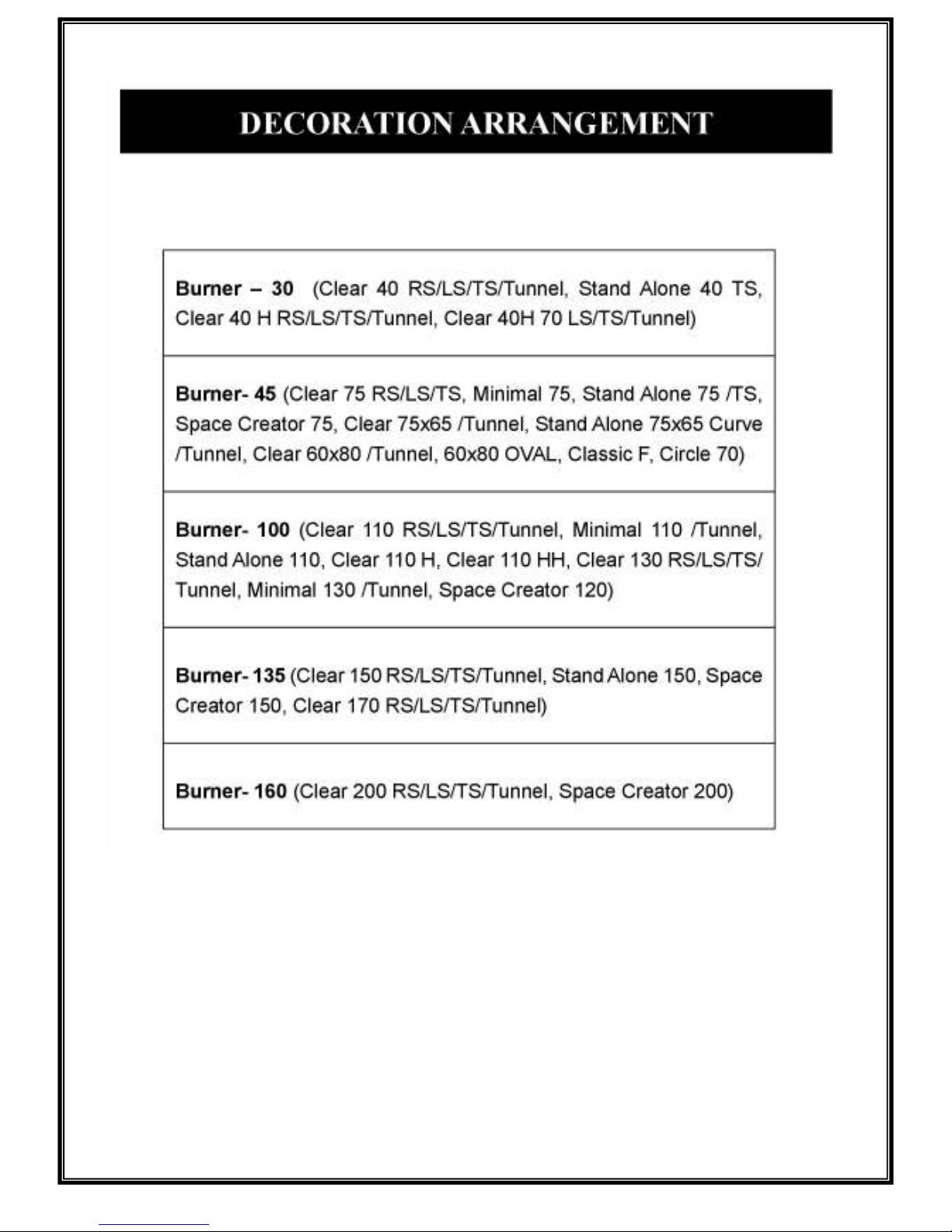
This manual covers the following appliances:
Clear 40 RS/LS/TS/Tunnel, Stand Alone 40 TS, Clear 40 H RS/LS/TS/Tunnel,
Clear 40H 70 LS/TS/Tunnel, Clear 75 RS/LS/TS, Stand Alone 75 ITS, Minimal
75, Space Creator 75, Clear 75x65 /Tunnel, Stand Alone 75x65 Curve /Tunnel,
Clear 60x80 I Tunnel, 60x80 OVAL, Classic F, Circle 70, Clear 110 RS/LS/TS/
Tunnel, Minimal 110 /Tunnel, Stand Alone 110, Clear 110 H, Clear 110 HH Clear
130 RS/LS/TS/ Tunnel, Minimal 130 /Tunnel, Space Creator 120, Clear 150 RS/
LS/TS/Tunnel, Space Creator 150, Stand Alone 150, Clear 170 RS/LS/TS/
Tunnel, Clear 200 RS/LS/TS/Tunnel, Space Creator 200
CONTENTS
GENERAL INFORMATION
Important Safety Notice 5
General Fitting Information 6
Battery Type (Remote Versions Only) 6
INSTALLER INFORMATION
Ventilation 7
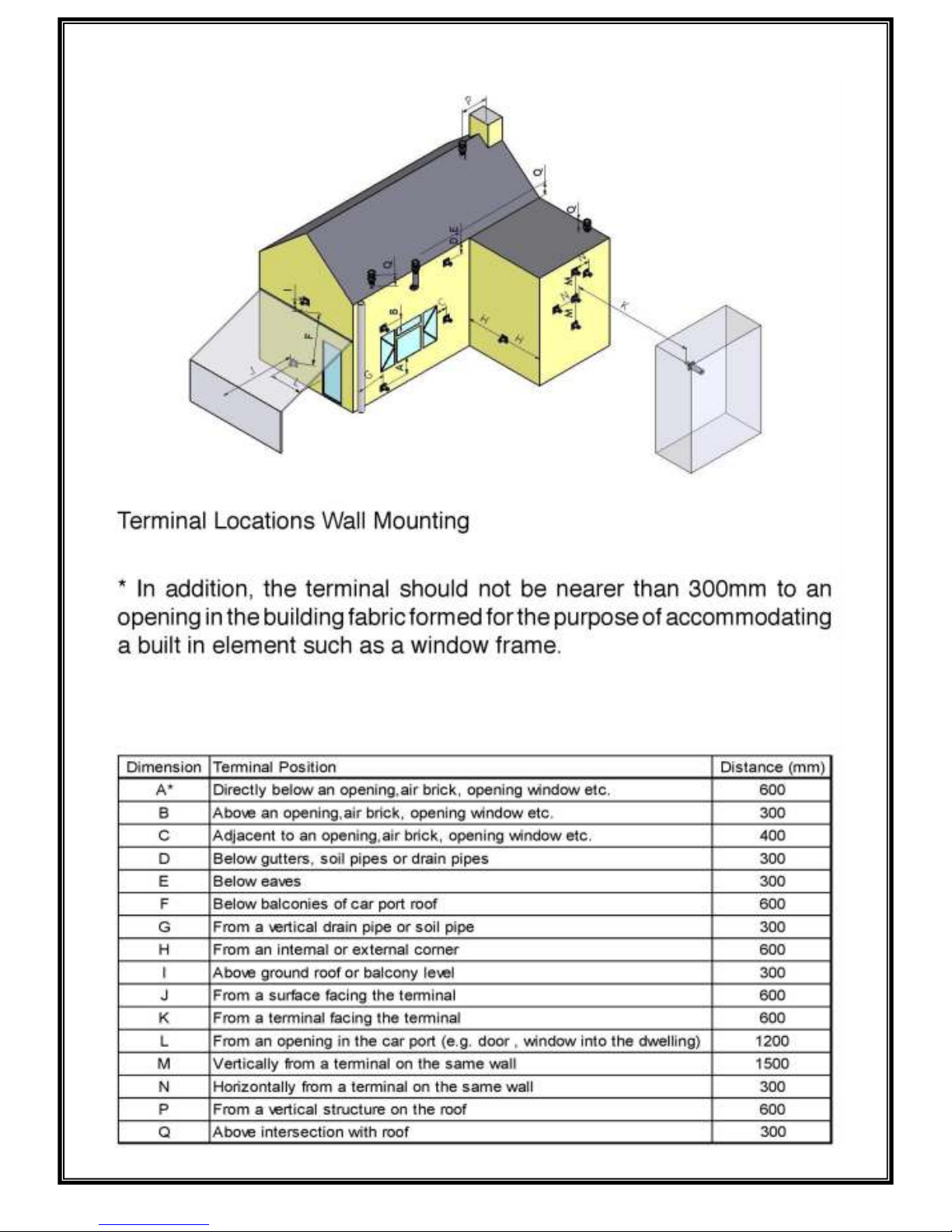
General Balanced Flue Notes and Position 7
Commissioning the Appliance 10
Servicing Instructions 11
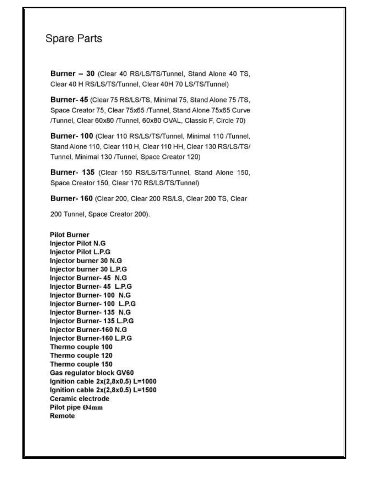
Spare Parts 12
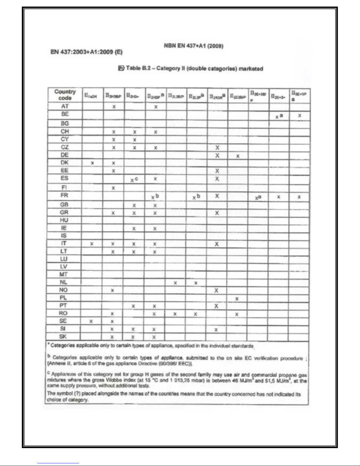
Countries of Destination / Gas Categories 13
Instructions for Changing the Burner From Natural Gas to LPG 16
TECHNICAL INFORMATION
Technigas CE Approval Test Results 21
Contents - Single Step Burner (N) 21
Contents - Double Step Burner (D) 22
Minimum Clearances to Combustible Materials 23
DECORATION ARRANGEMENT
English Branches 37
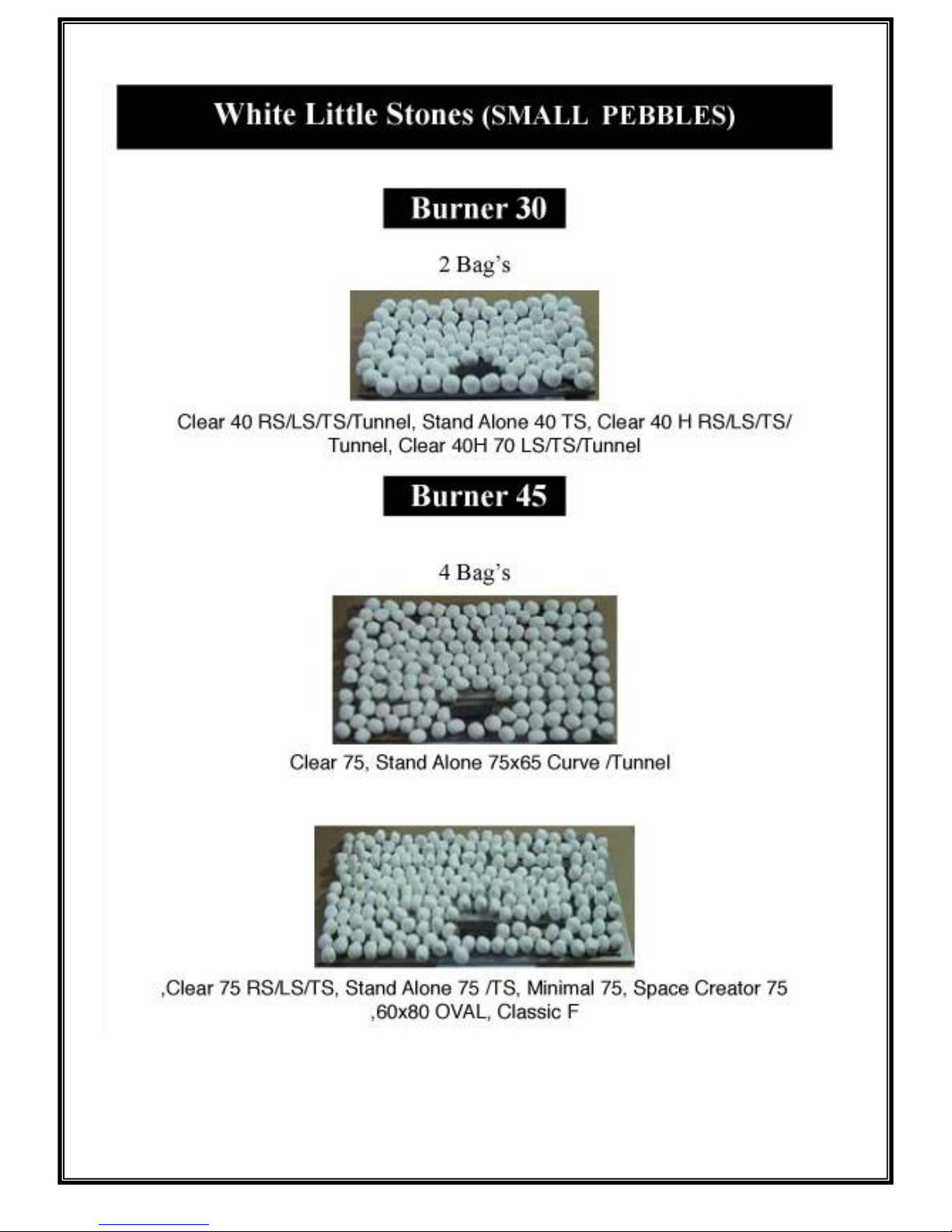
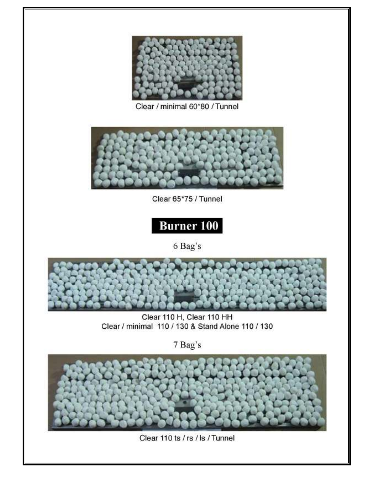
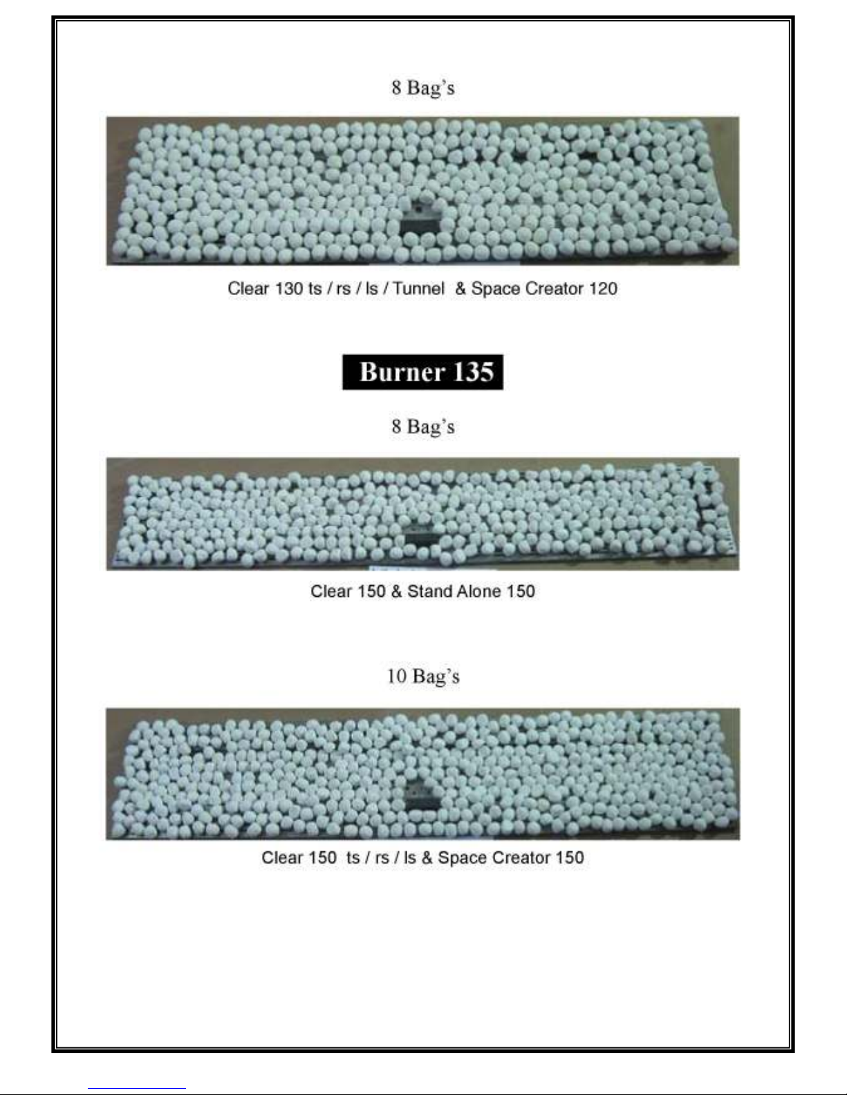
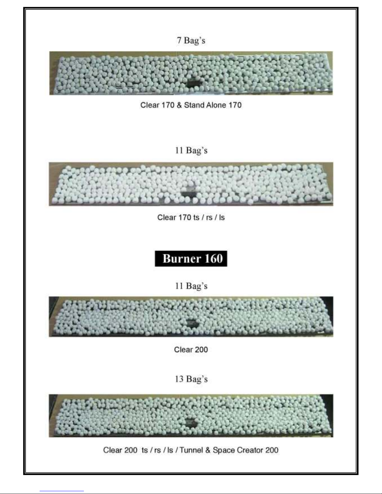
Small Pebbles 42
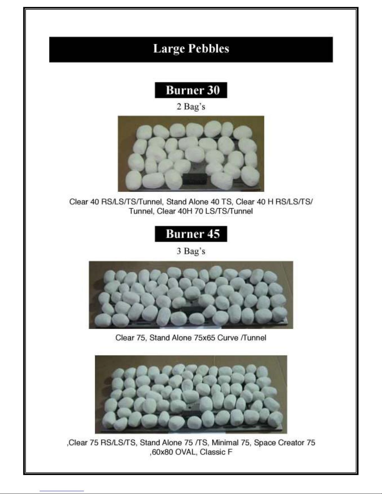
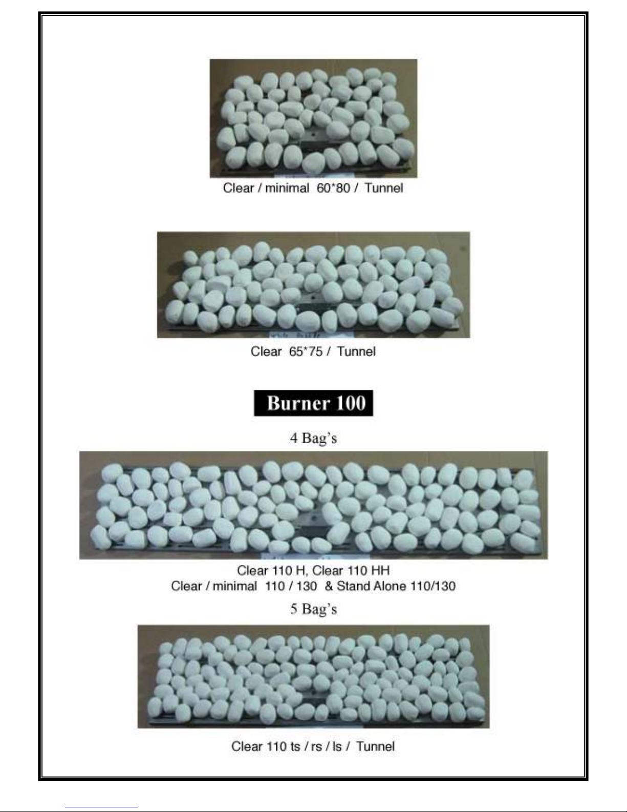
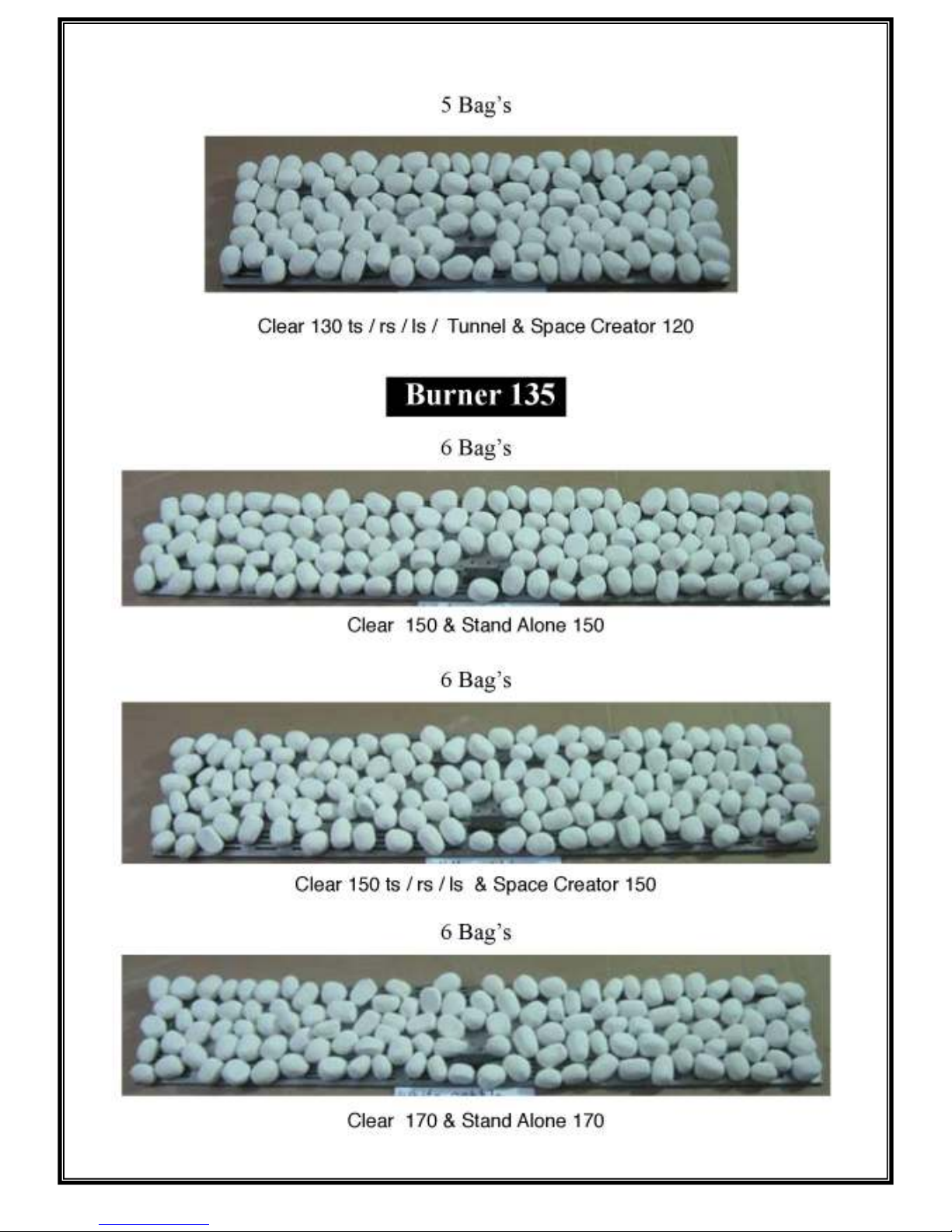
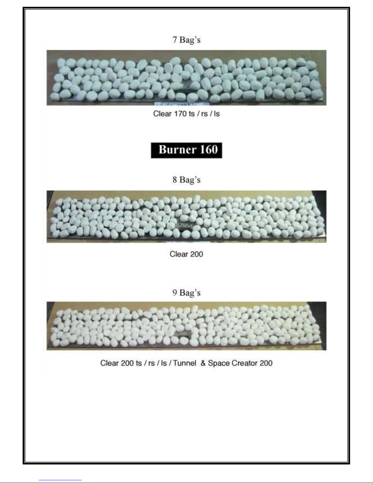
Large Pebbles 46
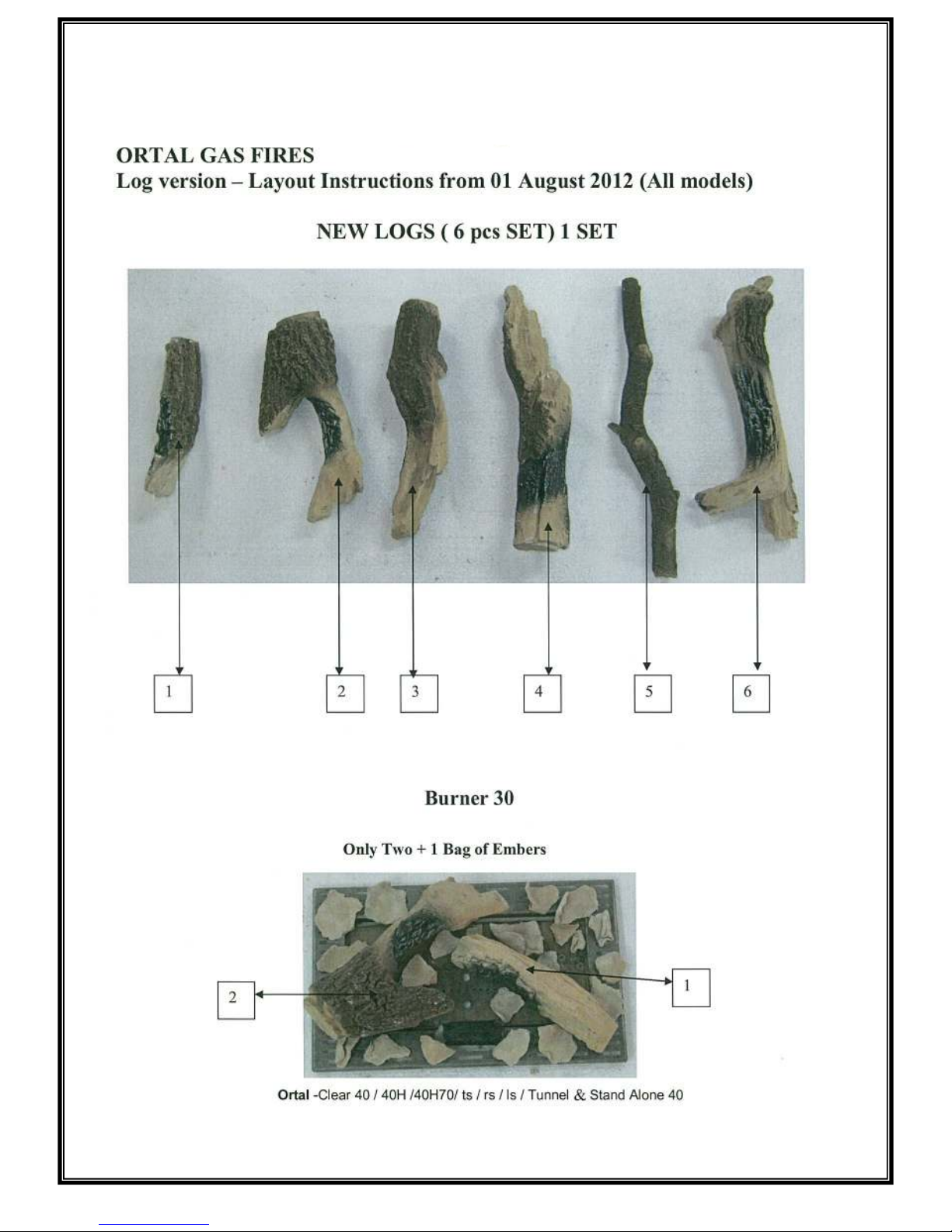
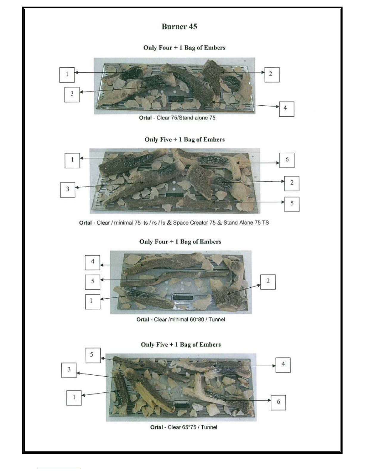
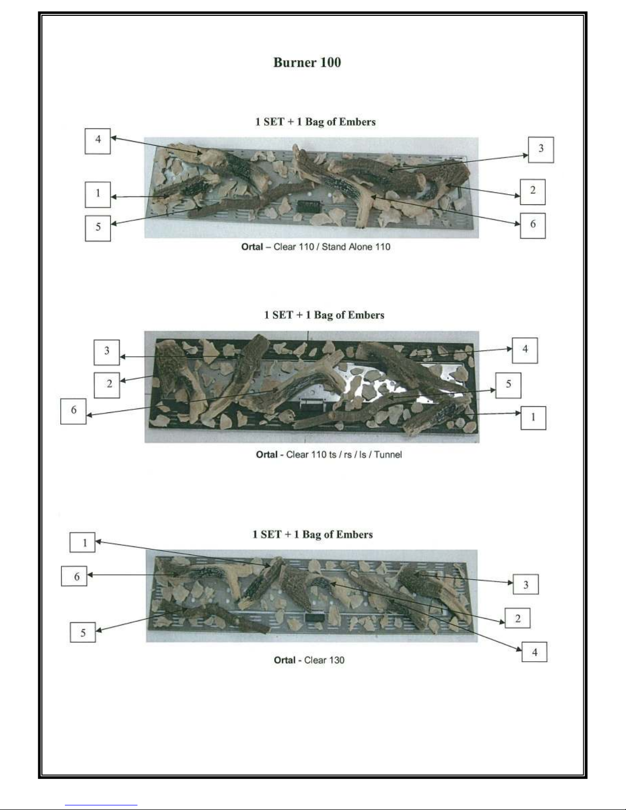
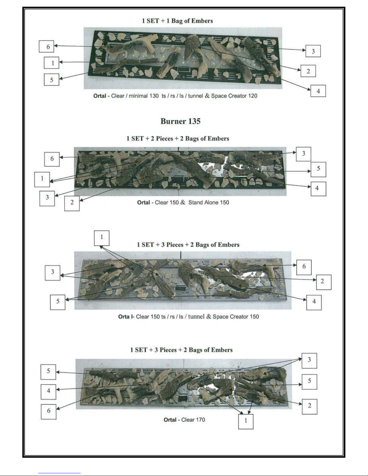
Refractory Clay Logs (6 piece set) 50
FLUE
Flue Design Options 55
Troubleshooting 61
Operating Instructions 62
OPERATING INSTRUCTIONS
Page 5

5
Ortal Technical Guide December 2015
This appliance has a ceramic Fire-bed arrangement; this contains
Refractory
Ceramic Fibres, which are man-made vitreous silicate fibres.
Excessive
exposure
to
these materials can cause irritation to eyes, skin and
respiratory organs.
Hence
we recommend that when handling these
materials the release of dust should
be
kept to a minimum. During
installation and servicing we recommend that a HEPA filtered vacuum be
used to remove any dust and soot in and around the fire. If
any
of the
ceramic fire-bed components need to be replaced we recommend that
the
removed parts be sealed in a heavy-duty polythene bag, and be labelled as
RCF
waste. RCF is not "Hazardous waste" and can be disposed of at a
licensed
tipping
site for the disposal of industrial
waste.
The appliance incorporates a permanent pilot. This is located on the front
of
the
burner, and must not be adjusted by the installer. This system must not
be put
out
of operation, and if any parts require changing, only original
manufacturer
parts
shall be
used.
This appliance is designed to be used either Natural or LPG gas however,
each
individual appliance is only capable of running off the type of gas
specified at
the
time of purchase. It is important to note that once a type of
gas has been
specified
the stove cannot run off any other type. The type of
gas that your stove is
capable
of burning is stated on the data information
panel.
This appliance has been designed, tested and approved to meet standards in
place
for product use, performance and safety. Installation of your appliance
must
comply
with current building regulations. It is therefore recommend
that a registered
gas
installer be employed for this task. The engineer will
provide you with
information
about the safety limits of the installation and
should fix a notice plate in a
place
where it can be readily
seen.
This appliance is designed as an efficient heating device and consequently all
body
parts become very hot in use. Except for the control knob and control
access door, which are designed to stay cool, all other parts are working
surfaces and
should
not be
touched.
The glass and frame on this appliance acts as a fireguard conforming to BS:
1945
—1971 and satisfies the Heating Appliance (Fireguards) regulations
1991.
No
part of the window or frame should be permanently removed. It
does not give
full
protection for young children or the infirm, extra protection
should be considered
for
these conditions conforming to BS 6539 or BS
6778.
Bearing in mind that the heat given off by this appliance may affect articles
placed
close to it, curtains should not be placed within
30cm.
The appliance is not designed as a
dryer. It is not therefore recommended
that
the
appliance be used in such a manner. Do not place any articles within
30cm of
this
appliance as this may result in damage to the
articles.
The installation must be carried out in accordance with the following
regulations:
IMPORTANT SAFETY NOTICE
Page 6

6
Ortal Technical Guide December 2015
The Building Regulations issued by the Department of the Environment, the
Building Standards (Scotland) (Consolidation) Regulations issued by the Scottish
Development Department.
BS 1251, BS 5440 part 1, BS 5871 part 2, BS 6461 part1, BS 6891 and BS 8303
In the Republic of Ireland the installation must also conform to the relevant standards,
particularly in regard to flue sizing and ventilation. Refer to documents IS813, ICP3,
IS327 and any other rules in force.
This appliance must be installed in accordance with the rules in force and used only
in a sufficiently ventilated space, and is intended for use on a gas installation with
a governed meter.
Before installation, ensure that the local distribution conditions (identification of the
type of gas and pressure) and the adjustment of the appliance are compatible. The
technical specification of this appliance is given on the rear page of this manual.
This appliance should not be used if the Glass is broken, and should never
be used with the Door open.
General Fitting Information
Inlet Pipe Connection 15mm Compression fitting supplied to fit gas valve
Chimney requirement Balanced Flue
Flame monitor Permanent Pilot
User control: Variable rotary control inc. integrated Piezo ignition, Permanent pilot
facility, Flame failure device and Oxygen Depletion Cut-out.
Before installation of these appliances, the area into which the fire is to be fitted
must be cleared of all debris (including dust), in particular combustible material.
The appliance must sit on a hearth (or base surface) sufficient to support the weight
of the fire. The firebox must then also be secured. Adjustable brackets are supplied
on the firebox for this purpose.
For model size 150 and over it is recommended that the glass is handled by 2 people.
See ‘Commissioning The Stove’
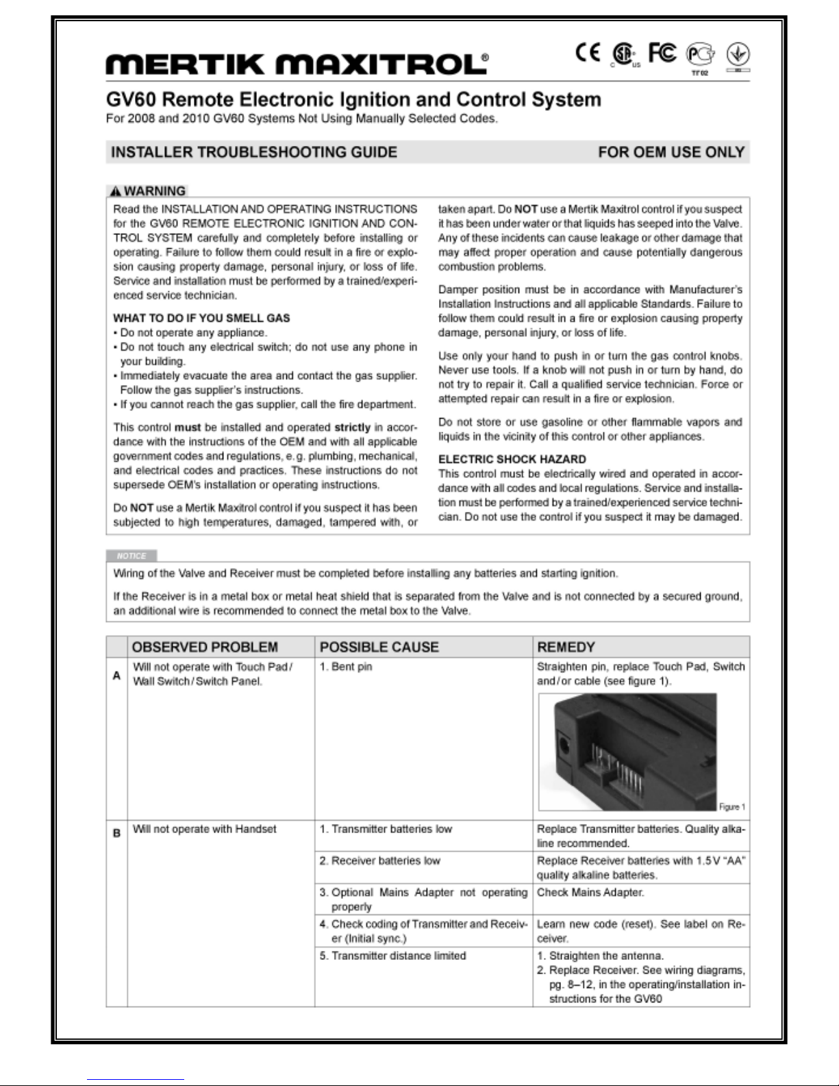
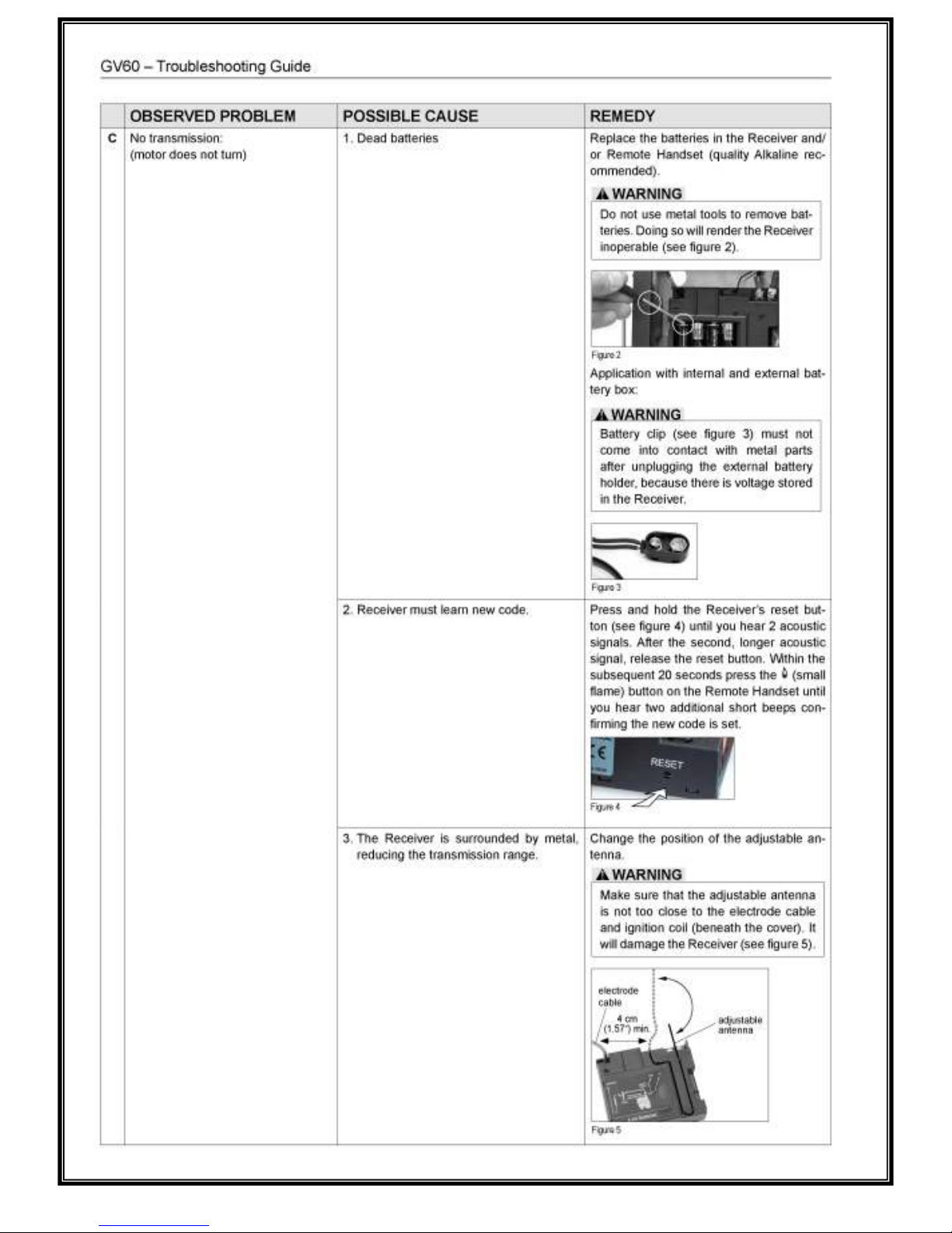
Battery type (Remote Versions only)
Receiver: 4 x AA.
Transmitter: 3 x AAA
If the Flame Supervision Device is extinguished either
intentionally or unintentionally, no attempt should be made to
re-light the gas until at least 3 minutes have elapsed.
Page 7

7
Ortal Technical Guide December 2015
Ventilation
This appliance can be installed in a completely sealed or mechanically
ventilated
house without extra ventilation and/or fume
extraction.
General Balanced Flue
Notes
There are many possibilities for installing this Concentric Balanced Flue
system
into a building, both Roof and Wall terminations are possible, and the flue
can
either be built into an existing chimney or a completely new flue system may
be
constructed.
The system is based upon a Concentric Flue system which utilises an inner flue
which passes through an outer flue, for flue size see ‘Flue Design Options’ . The
flue
gasses that are the products of combustion of the fire, pass through the inner flue
and are safely vented to the outside environment. The gap between the inner
and
outer flues is the channel by which the stove is supplied with air for
combustion.
These concentric flues terminate outside of the property in a terminal, this
terminal
will keep the expelled gasses and the fresh air for combustion separate. It
is
important that the terminal is not blocked, a suitable guard maybe required if
the
terminal is located at a "Low" level (usually when the terminal is within 2m of
floor
level).
The Balanced Flue gas appliance can be installed as an insertion into an
existing
or new fireplace. If an existing Flue or Chimney is to be utilised, then the
installation
engineer must be consulted. If the chimney has been previously used it must
be
professionally cleaned and certified as being sound and fit for
use.
The European CE approval on this appliance is restricted to the Flue systems as
specified by the supplier, thus the appliance must only be installed with the
original
flue system, no others may be
used
The gas fire, in combination with the concentric flue system, has been approved
in
accordance with the European CE-norm for gas appliances and may
therefore
be used only with this system. The guarantee is invalidated if the appliance
is
(completely or partially) installed using a different
system.
The concentric flue systems can be used with either a newly-built or
existing
chimney.
These appliances are designed with the "Firebox" raised up off the ground level
by
the built in "Base unit".
Thus these appliances require no special Hearth arrangements, as the floor will not
get hot and is protected by the steel construction of the "Base unit".
The appliance must not be fitted against a rear wall constructed from a
combustible
material; a gap of 300mm should be given all round the stove before
combustible
materials may be used in the wall construction.
If the appliance has to be located in an opening, a minimum clearance of
50mm
should be allowed to non-combustible
materials.
Page 8

8
Ortal Technical Guide December 2015
If the appliance is located in a recess, then the recess must have adequate
ventilation, we recommend a minimum total vent area of 200 cm 2.
The stove must be located at least 280mm from any combustible materials.
Timber Frame
Construction
Whilst it is possible to install room-sealed appliances in timber frame
properties
,
great care needs to be taken to ensure that the flue assembly does not interfere
with the weather proofing qualities of any outer wall which it may penetrate.
Before
attempting this work, further details need to be referenced, (e.g. "Gas Installations
in
Timber Frame Buildings" from the CORGI installer series in the UK).
Carport or Building
Extension
Where a flue terminal is sited within a carport or building extension,
it should
have
at least two completely open and unobstructed sides. The distance between
the
lowest part of the roof and the top of the terminal should be at least 600mm.
Note: A covered passageway should not be treated as a carport. Flues should not
be sited in a covered passageway between
properties.
Basements, Lightwells and Retaining
walls
Flue terminals should not be sited within the confines of a basement area, light well
or external space formed by a retaining wall, unless steps are taken to ensure
the
products of combustion can disperse safely at all times. It may be possible to
install
this Balanced Flue system in such a location provided that it is not sited lower
than
1m from the top level of that area to allow combustion products to disperse safely.
Flue terminals should be sited to ensure total clearance of the combustion
products
in accordance with the enclosed information.
When the products of combustion are discharged, they should not cause a
nuisance
to adjoining or adjacent properties and they should be positioned so that
damage
cannot occur to other parts of the building. If the outer wall surface is constructed of
combustible material, a non-combustible plate should be fitted behind the
terminal
projecting 25mm beyond the external edges of the
terminal.
Page 9
9
Ortal Technical Guide December 2015
Page 10
10
Ortal Technical Guide December 2015
Terminal Locations Roof
Termination
"Distance" = minimum distance required for positioning of the outlet to avoid
adverse
effects with respect
to:
A. A ventilation opening serving an occupied room, a toilet or a
bathroom
B. A heating air supply, when the supply flows through an occupied
room.
C.
A window that can be opened and that is near an occupied
room, a
toilet or
a
bathroom.
(*)
If the required distance cannot be
achieved, the outlet position rules
take
precedence.
(**)
If the outlet is positioned at least 1 m higher than the intake supply opening, or a
window that can be
opened.
(***)
If the required distance cannot be achieved, the position of the outlet must
be
at least 1 m above the highest
facade/roof.
Important note for Roof Terminations,
(C31).
When installing the appliance with a roof termination (classification C31), it
is
important to fit a 30mm flue restriction strip across the flue outlet inside the stove.
COMMISSIONING THE
STOVE
A soundness test MUST be made before the installed stove is left with
the
customer.
Ensure that the fire is burning at full rate for a minimum of 5 minutes to warm
the
flue.
If there are
problems,
the flue may require
attention.
The stove will produce an odour and/or smoke for the first few hours of use.
Please
ventilate the room. Also please note that during this initial burning
period, a grey
dust deposit will be formed on the inside of the glass, please clean this
before
leaving the appliance with the
customer.
Distance: Outlet
A,B or C
At the same roof level > 6m (*)
At different roof level >3m (*) (**)
At a lower positioned wall > 2m (**)
At a higher sloping surface > 6m (***)
To avoid adverse effects
Page 11

11
Ortal Technical Guide December 2015
For model size 150 and over it is recommended that the glass is handled by 2 people.
Use appropriate glass suction cup lifters where necessary, support with gloved hands
as much as possible. Place the glass on a sheet or soft surface to protect the edges.
When replacing glass the retaining screws should be ‘finger tight plus a quarter turn’.
Do not over tighten or the glass may crack.
For TS, LS, RS and Island models
When the glass is finally assembled ensure the glass to glass joints are pushed
together before tightening the retaining screws and cold. It is recommended that a thin
smear of high temperature silicone sealant is used on the glass to glass joints:
Place masking tape down the edges of the adjoining glass to protect the faces, smear
a small amount of silicone to seal the joint, wiping away excess so only a small film fills
the corner of the joint and remove tape before operating the fire. At service this film
can be carefully cut with a sharp thin blade, taking care not to damage the glass
edges. On reassembly the sealing procedure is repeated.
SERVICING INSTRUCTIONS
The following outlines only the minimum work that should be performed on an
annual basis. This service work, like any other work on the appliance, must only be
done by a qualified and competent engineer who is Gas Safe registered.
Open the door and remove all ceramics.
Remove any debris from the top of the burner using a vacuum cleaner and brush.
Inspect the burner unit.
Perform an ignition check.
Perform a flame failure check
There should be no need to service the burner. If however this is required, then the
engineer should check the setting pressure at the gas valve.
Brush off and replace ceramic arrangement as shown in this manual, replacing any
broken or damaged pieces.
Check all seal on door (including glass) and refit the door. See ‘Commissioning the
Stove’
Check the installation for gas leaks.
Check the flue joints are secure, including those in voids, and that the flue is working
satisfactorily.
Check that there are no flue products leaking from the appliance.
If
any parts need to be replaced use only genuine manufacturer parts, non-standard
parts will invalidate the guarantee and may be dangerous.
Natural Gas Burner
Pressures
Burner Size
Double Step Burner
Both Rows Burning
45 10 mbar 16.3 mbar
100 10.7 mbar 6.5 mbar
135 5.7 mbar 11.4 mbar
160 8.8 mbar 16.1 mbar
Single Step Burner
Page 12
12
Ortal Technical Guide December 2015
Page 13

13
Ortal Technical Guide December 2015
Page 14

14
Ortal Technical Guide December 2015
Page 15
15
Ortal Technical Guide December 2015
Page 16
16
Ortal Technical Guide December 2015
Page 17
17
Ortal Technical Guide December 2015
Page 18

18
Ortal Technical Guide December 2015
Page 19
19
Ortal Technical Guide December 2015
Page 20

20
Ortal Technical Guide December 2015
Page 21

21
Ortal Technical Guide December 2015
Page 22

22
Ortal Technical Guide December 2015
Page 23
23
Ortal Technical Guide December 2015
Page 24
24
Ortal Technical Guide December 2015
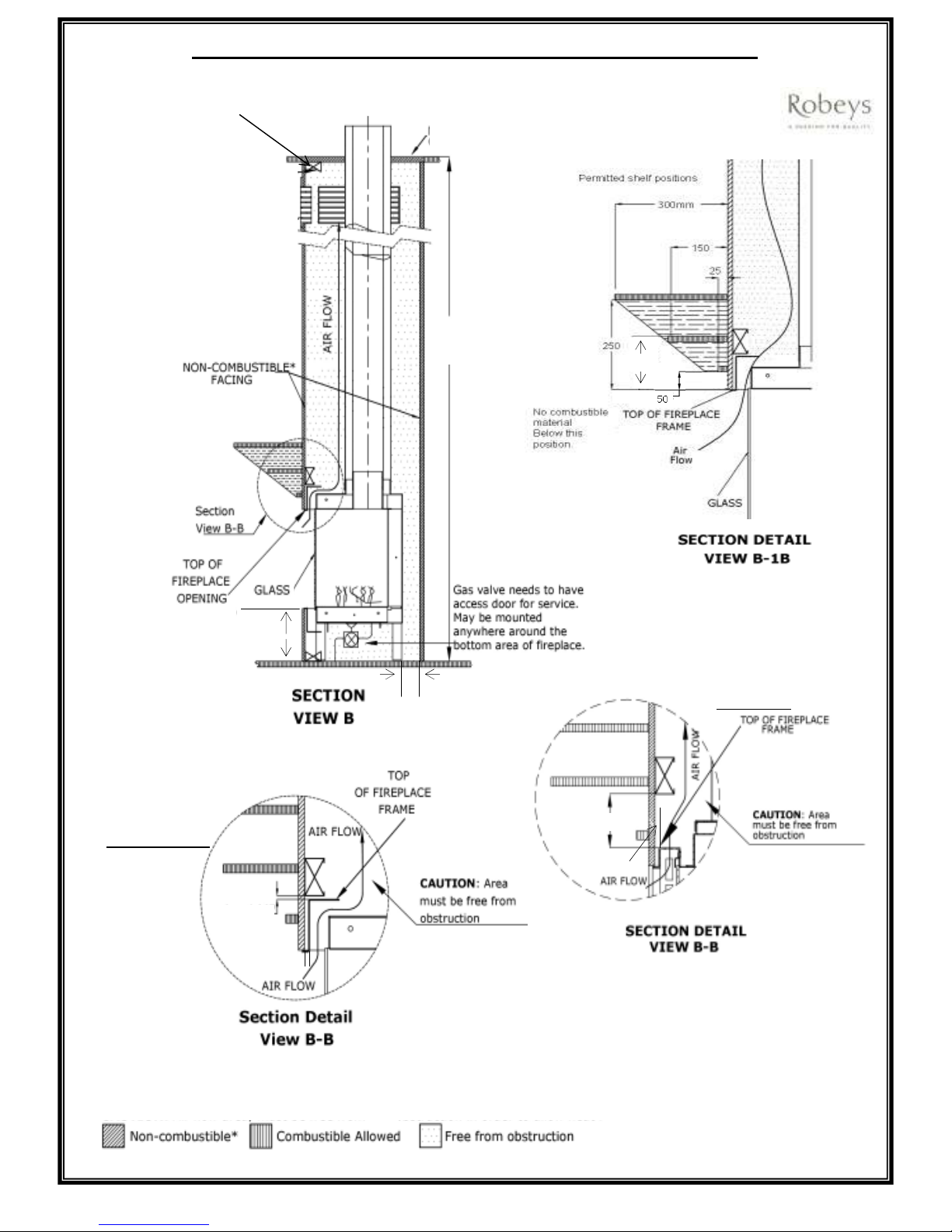
Use metal studding for construction and support
CAUTION:
Vent Opening, minimum 800cm2 using vent
grille or shadow gap.
This can be reduced to:400cm2 for 40 to 75 size models
500cm2 for 110 to 130 size models
600cm2 for 150 to 200size models
Providing no heat sensitive device (e.g.
television) is mounted to the wall.
(For TV mounting see separate sheet)
Combustible materials must not be
used within the enclosure.
min. 6mm
min. 6mm
min. 225mm
min. 50mm
Clear Front / TS / LS / RS / Space Creator Flat Fireplace
Mantel (Section B-B & Sides) Clearances
Non-combustible material *
ceiling to the enclosure.
Non-combustible material *
in the enclosure.
All other models
Clear Front
Min 100mm
min. 6mm
Non-combustible materials: Materials applicable for the installation of Ortal fireplaces within the specified clearance dimensions are described as non-combustible materials. A suitable material is Skamotec 225 board.
Suitable access to permit examination of the flue joints at service should be provided.
CAUTION. Air flow area must be free from any obstruction in order to allow heat from the cavity to be released.
Drawing NOT to scale. All dimensions in mm.
August 2014
125
Page 25
25
Ortal Technical Guide December 2015
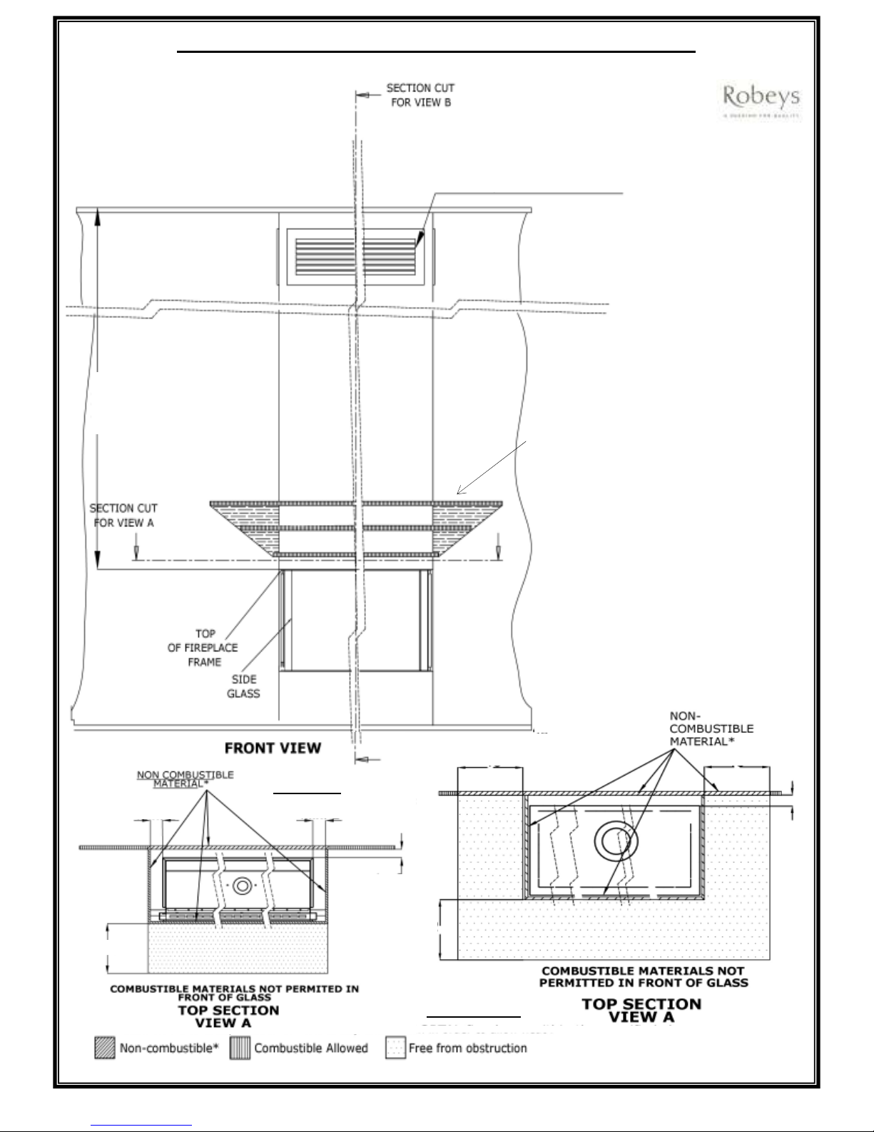
TS / LS / RS / Space Creator Flat Fireplace
Mantel (Front & Top) Clearances
Clear Front / TS / LS / RS / Space Creator Flat Fireplace
Mantel (Section B-B & Sides) Clearances
1000 mm 1000 mm
1000 mm
50 mm
CAUTION:
Vent Opening or shadow gap.
610mm Min
clearance from ‘ceiling’
to appliance
TS Example shown
Min 50 mm
Min 50 mm
Min 50 mm
1000 mm
Clear Front
All other models
Drawing NOT to scale. All dimensions in mm.
August 2014
Page 26
26
Ortal Technical Guide December 2015
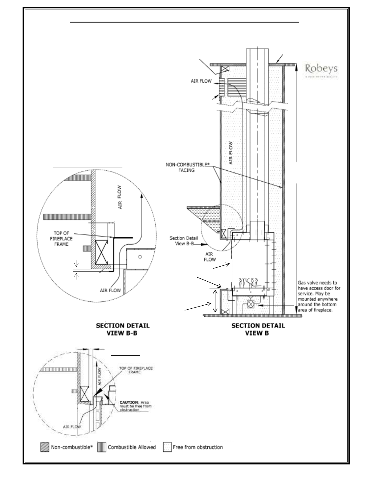
Clear Front / TS / LS / RS / Space Creator Offset Fireplace
Mantel (Section B-B & Sides) Clearances
Non-combustible materials: Materials applicable for the installation of Ortal fireplaces within the
specified clearance dimensions are described as non-combustible materials. A suitable material
is Skamotec 225 board.
Suitable access to permit examination of the flue joints at service should be provided.
CAUTION. Air flow area must be free from any obstruction in order to allow heat from the
cavity to be released.
Use metal studding for
construction and support
Non-combustible material *
ceiling to the enclosure.
CAUTION:
Vent Opening, minimum 800cm2 using vent
grille or shadow gap.
This can be reduced to:400cm2 for 40 to 75 size models
500cm2 for 110 to 130 size models
600cm2 for 150 to 200size models
Providing no heat sensitive device (e.g.
television) is mounted to the wall.
(For TV mounting see separate sheet)
Non-combustible material *
in the enclosure.
TS / LS / RS / Space Creator
Glass
If less than
225mm, the hearth
should extend
300mm
Non Combustible
Hearth
Min. 6mm
Min. 6mm
Clear Front
Combustible materials must NOT be used within the enclosure.
Drawing NOT to scale. All dimensions in mm.
August 2014
Shelf dimensions
as for Flat Fireplaces
6mm
Page 27
27
Ortal Technical Guide December 2015
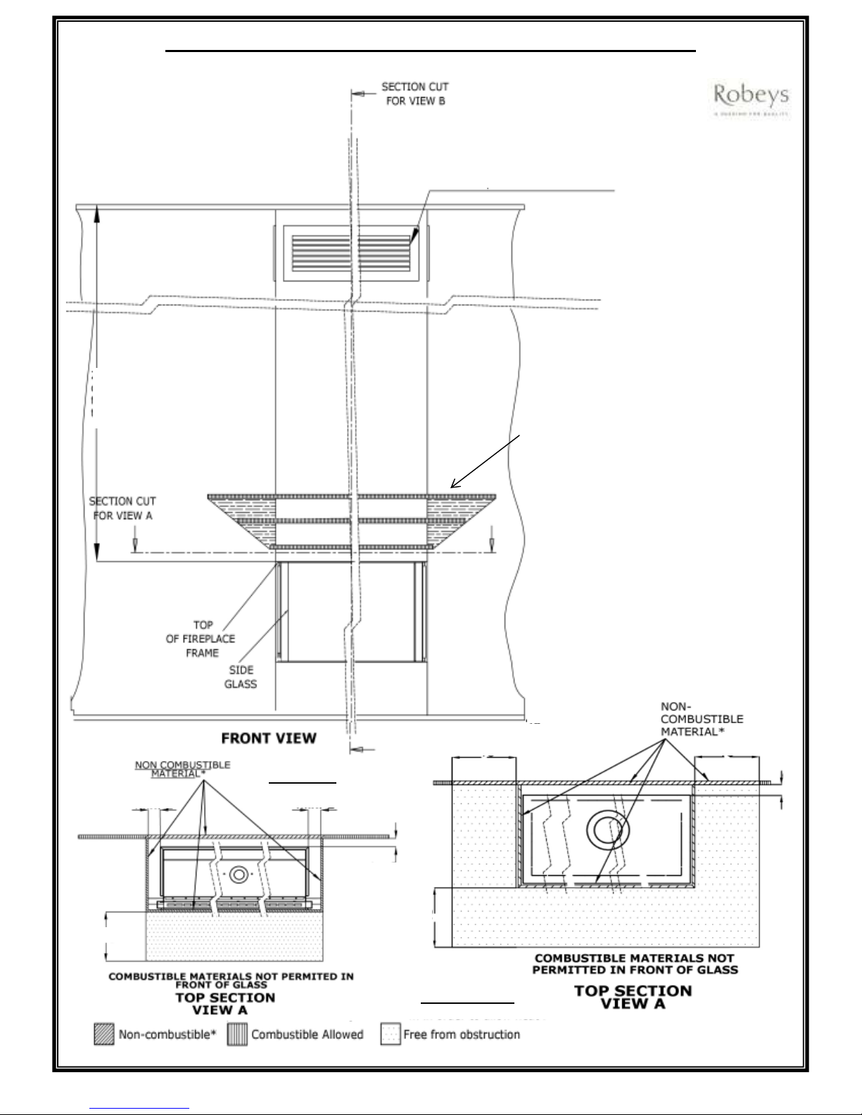
TS / LS / RS / Space Creator Flat Fireplace
Mantel (Front & Top) Clearances
Clear Front / TS / LS / RS / Space Creator Offset Fireplace
Mantel (Section B-B & Sides) Clearances
1000 mm 1000 mm
1000 mm
50 mm
CAUTION:
Vent Opening or shadow gap.
610mm Min
clearance from ‘ceiling’
to appliance
TS Example shown
Min 50 mm
Min 50 mm
Min 50 mm
1000 mm
Clear Front
All other models
Drawing NOT to scale. All dimensions in mm.
August 2014
Page 28
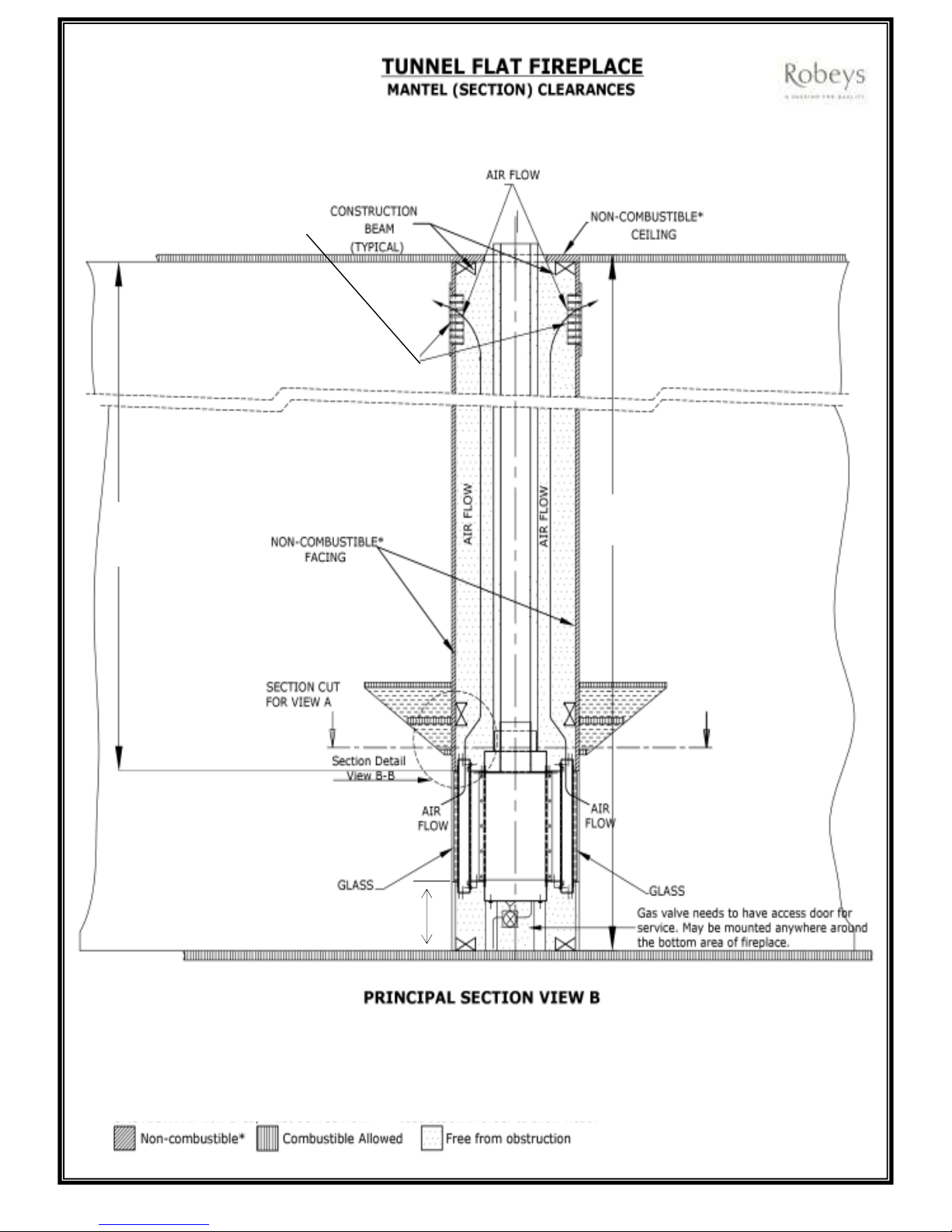
28
Ortal Technical Guide December 2015
CAUTION:
Vent Opening, minimum 800cm2 using
vent grille or shadow gap. (Can be either
side).
This can be reduced to:400cm2 for 40 to 75 size models
500cm2 for 110 to 130 size models
600cm2 for 150 to 200size models
Providing no heat sensitive device (e.g.
television) is mounted to the wall.
(For TV mounting see separate sheet)
610mm min
clearance
from ceiling
to appliance.
Non-combustible
material in the
enclosure
Non-combustible materials: Materials applicable for the installation of Ortal fireplaces within the specified clearance dimensions are described as non-combustible
materials. A suitable material is Skamotec 225 board.
Suitable access to permit examination of the flue joints at service should be provided.
CAUTION. Air flow area must be free from any obstruction in order to allow heat from the cavity to be released.
Drawing NOT to scale. All dimensions in mm.
August 2014
Min 225 mm
Page 29
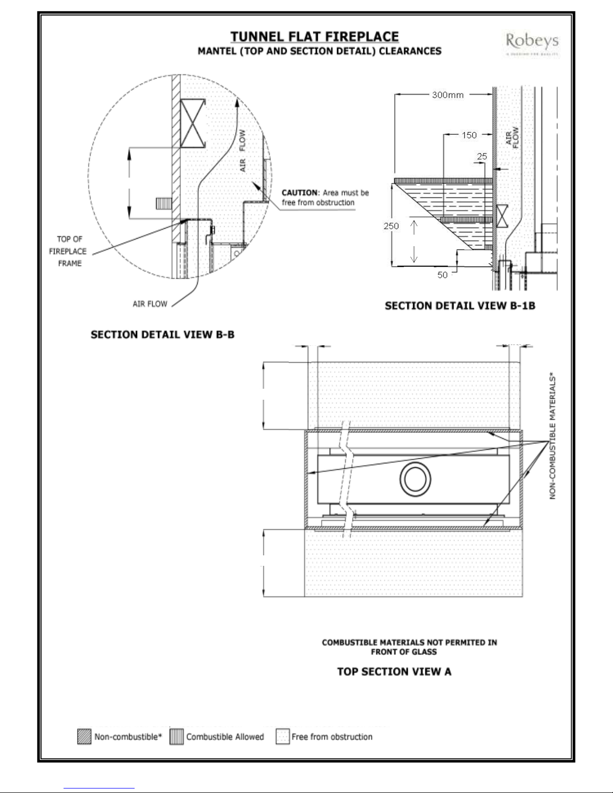
29
Ortal Technical Guide December 2015
100mm
min. 50mm
min. 50mm
1000mm
1000mm
Non-combustible materials: Materials applicable for the installation of Ortal fireplaces within the specified clearance dimensions are described as non-combustible
materials. A suitable material is Skamotec 225 board.
Suitable access to permit examination of the flue joints at service should be provided.
CAUTION. Air flow area must be free from any obstruction in order to allow heat from the cavity to be released.
Drawing NOT to scale. All dimensions in mm.
August 2014
125
Page 30
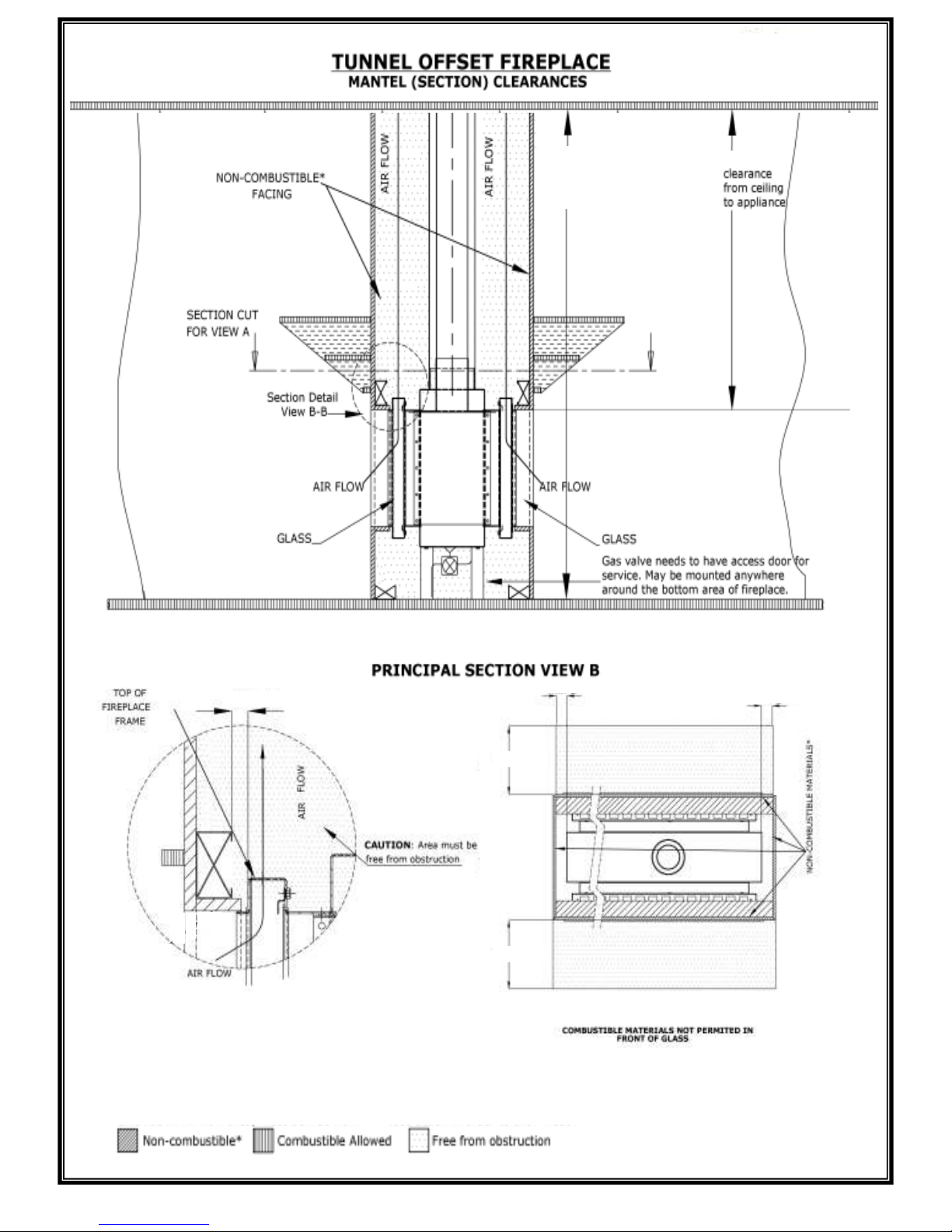
30
Ortal Technical Guide December 2015
Page 30
Non-combustible
material * in the
enclosure.
min. 6mm
min. 50mm
min. 50mm
1000mm
Non-combustible materials: Materials applicable for the installation of Ortal fireplaces within the specified clearance dimensions are described as noncombustible materials. A suitable material is Skamotec 225 board.
Suitable access to permit examination of the flue joints at service should be provided.
CAUTION. Air flow area must be free from any obstruction in order to allow heat from the cavity to be released.
Drawing NOT to scale. All dimensions in
August 2014
1000mm
610mm Min
Shelf dimensions
as for Flat
Fireplaces
Page 31
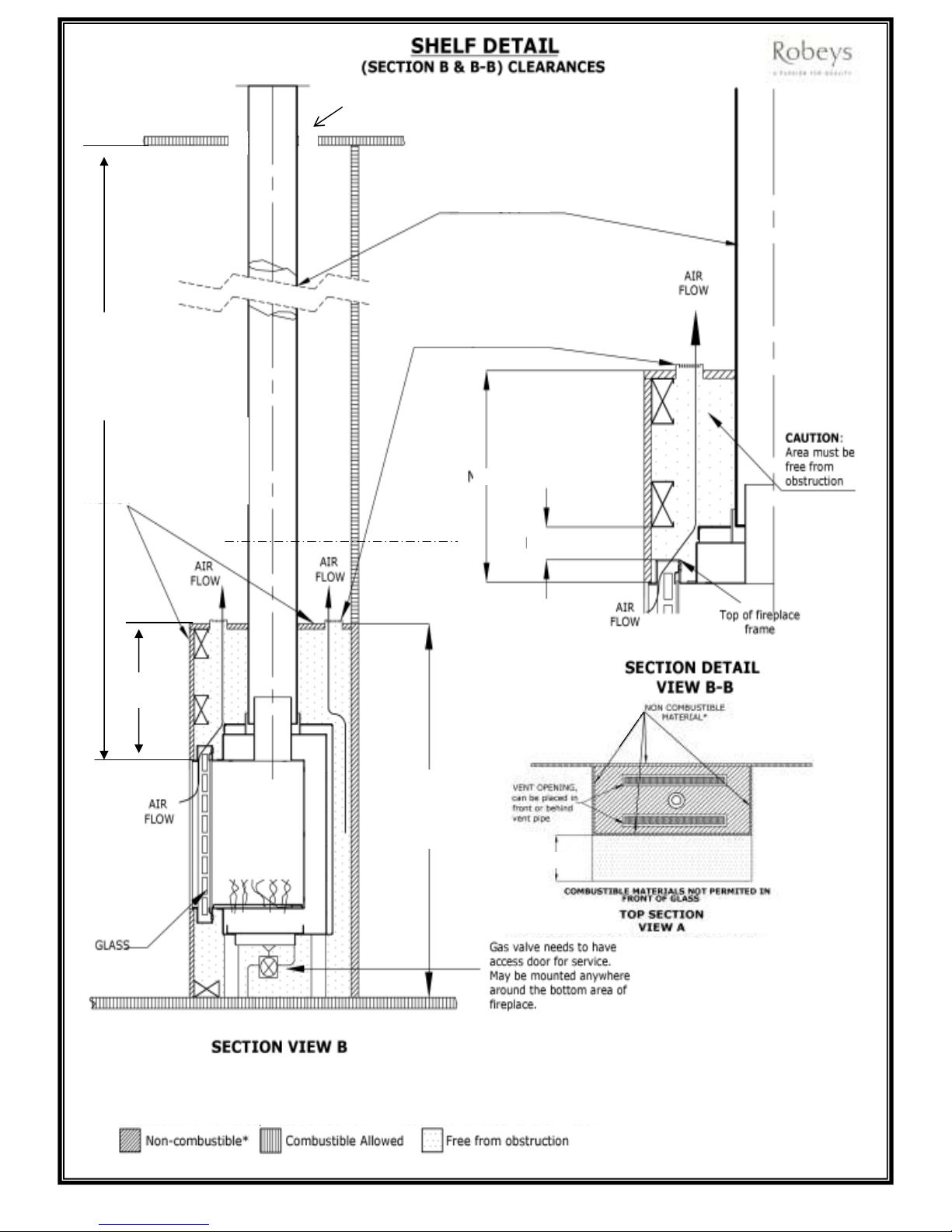
31
Ortal Technical Guide December 2015
Page 31
CAUTION:
Vent Opening, minimum 800cm2 using
Exposed flue
pipe
min. 250mm
min. 100mm
Use metal
studding for
construction and
support
Non combustible
facing and ceiling for
enclosure
Non combustible
material in the
enclosure
1000mm
610 min
clearance from
ceiling to
appliance
Min 250 mm
Use metal
studding for
construction and
Section cut
for View A
Non-combustible materials: Materials applicable for the installation of Ortal fireplaces within the specified clearance dimensions are described as noncombustible materials. A suitable material is Skamotec 225 board.
Suitable access to permit examination of the flue joints at service should be provided.
CAUTION. Air flow area must be free from any obstruction in order to allow heat from the cavity to be released.
Drawing NOT to scale. All dimensions in mm.
August 2014
Non-combustible suitable fire
stop
Page 32
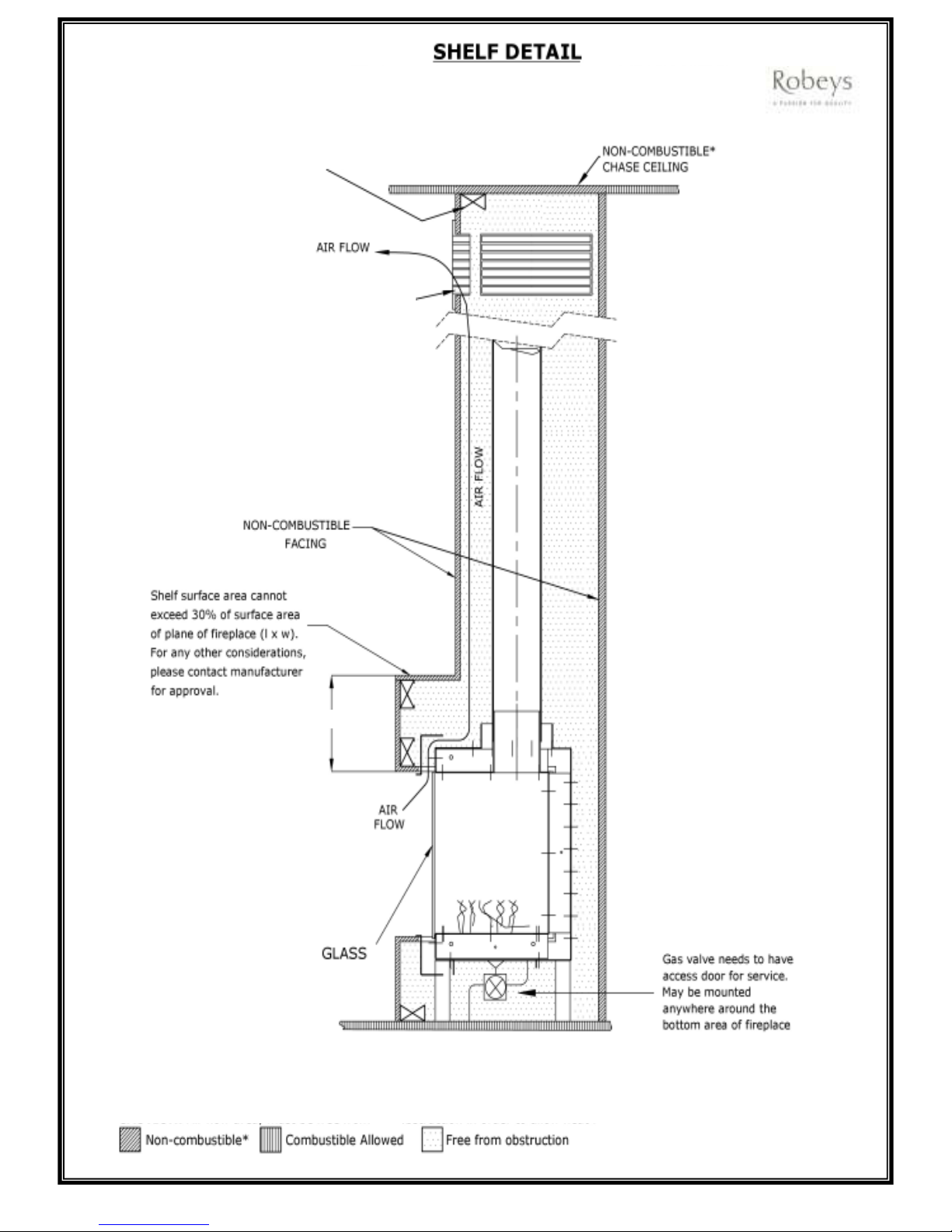
32
Ortal Technical Guide December 2015
Page 32
Min 250mm
CAUTION:
Vent Opening, minimum 800cm2 using
vent grille or shadow gap.
Fitting a heat sensitive device ( e.g. TV )
above the fire is NOT recommended.
Use metal studding for
construction and support
( Section without exposed flue pipe )
CLEARANCES
Non-combustible materials: Materials applicable for the installation of Ortal fireplaces within the specified clearance dimensions are described as noncombustible materials. A suitable material is Skamotec 225 board.
Suitable access to permit examination of the flue joints at service should be provided.
CAUTION. Air flow area must be free from any obstruction in order to allow heat from the cavity to be released.
Drawing NOT to scale. All dimensions in mm.
August 2014
Page 33
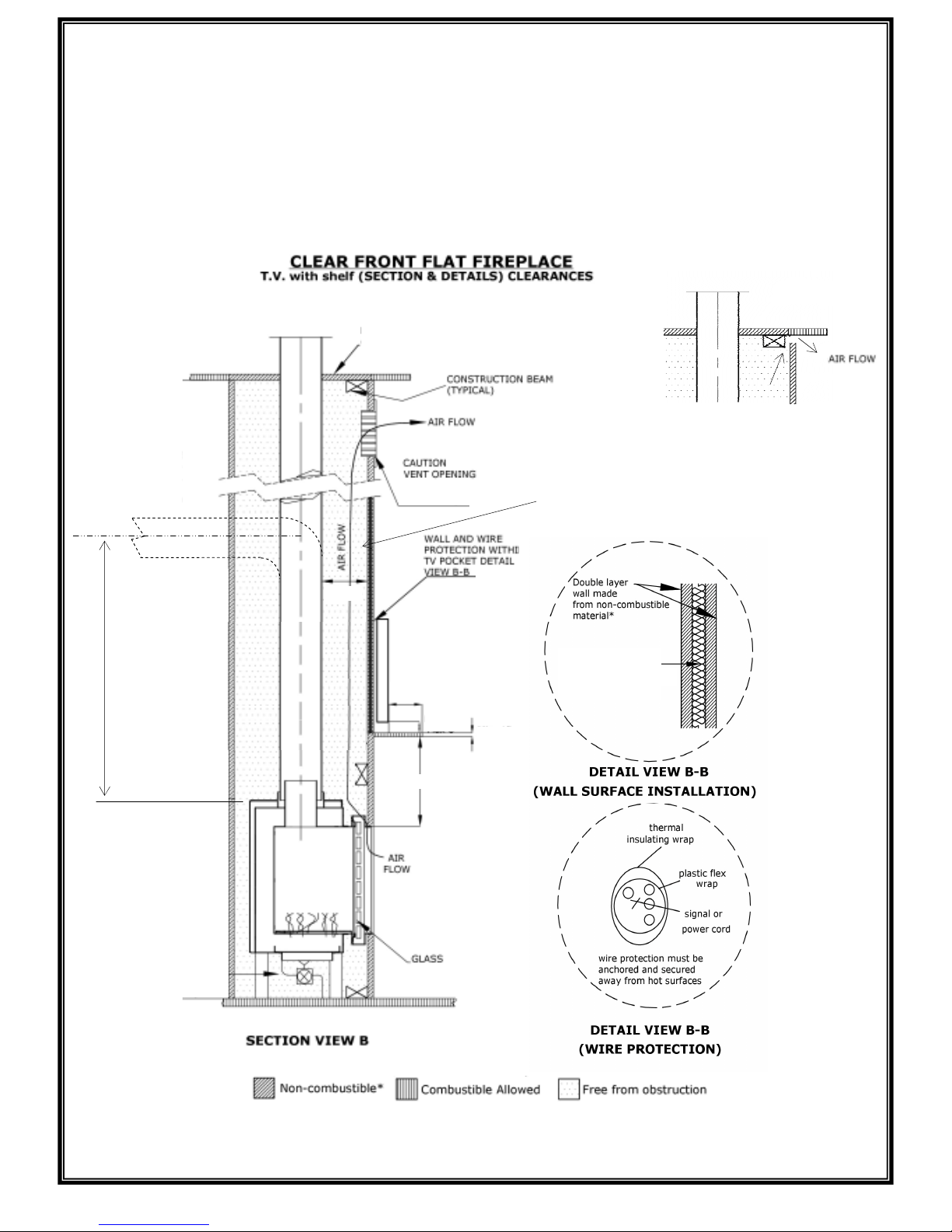
33
Ortal Technical Guide December 2015
If you wish to install a flat screen television or similar electronic device above your Ortal gas fire, here are some things you should
consider.
Most TV manufacturers have specified in their instructions that the TV should not be installed on, near or above a heat source. Ultimately, the decision of the TV location rests solely with the house holder.
Robeys and Ortal will not be held liable for any adverse affects on a TV or other equipment located near to the fire.
These drawings are suggestions as a guide to reduce temperatures for those consumers who decide to locate their TV’s above the
fire.
Use heat resistant cable
Min 50
Min
25mm
The TV
must be
Min 50
Max 150
above the
shelf
Min 800cm2
Non-combustible material must be used where
shown
This advisory sheet must be read in conjunction with the main installation instructions
supplied with the appliance
Use heat resistant cable
Minimum 25mm thermal
insulation sheet which can
withstand 120 °C
Min 50
Min 250
Ensure that the horizontal cross sectional area of the fireplace
enclosure is at least 800cm2 to allow adequate airflow.
Dimensions in mm
Shadow Gap.
Alternative ventilation arrangement.
Vent opening Min 800cm2
Min 1000mm
or more.
90°
Page 34
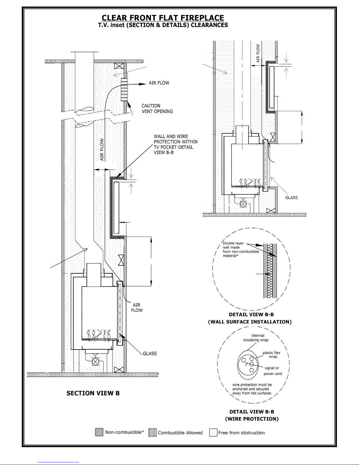
34
Ortal Technical Guide December 2015
Flue may need to be offset
Use heat resistant cable
Minimum 25mm thermal
insulation sheet which can
withstand 120 °C
Non-combustible material must be used where
shown
This advisory sheet must be read in conjunction with the main installation instructions
supplied with the appliance
FLAT FIREPLACE
Min 300mm
Min 50mm
Min
50mm
Min 50mm
clearance all
round the
Min 50mm
clearance all
round the
Min 50mm
Ensure that the horizontal cross sectional
area of the fireplace enclosure is at least
800cm2 to allow adequate airflow.
Min 800cm2
Min 50mm
Min 300mm
Dimensions in mm
AIR
FLOW
OFFSET
FIREPLACE
Offset only
allowed on
vertical flue.
Page 35
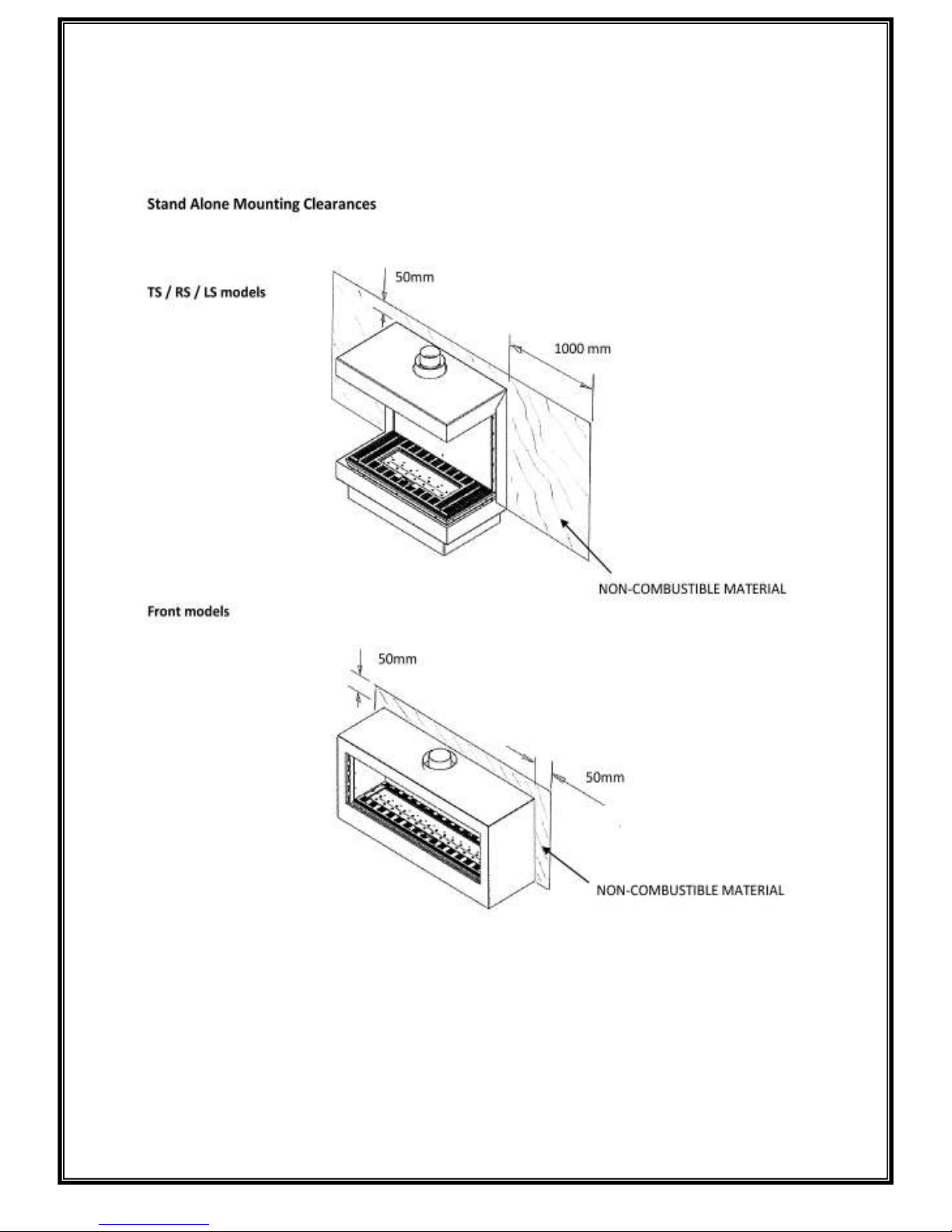
35
Ortal Technical Guide December 2015
Page 36
36
Ortal Technical Guide December 2015
Page 37

37
Ortal Technical Guide December 2015
Page 38
38
Ortal Technical Guide December 2015
Page 39
39
Ortal Technical Guide December 2015
Page 40
40
Ortal Technical Guide December 2015
Page 41

41
Ortal Technical Guide December 2015
Page 42
42
Ortal Technical Guide December 2015
Page 43
43
Ortal Technical Guide December 2015
Page 44
44
Ortal Technical Guide December 2015
Page 45
45
Ortal Technical Guide December 2015
Page 46
46
Ortal Technical Guide December 2015
Page 47
47
Ortal Technical Guide December 2015
Page 48
48
Ortal Technical Guide December 2015
Page 49
49
Ortal Technical Guide December 2015
Page 50
50
Ortal Technical Guide December 2015
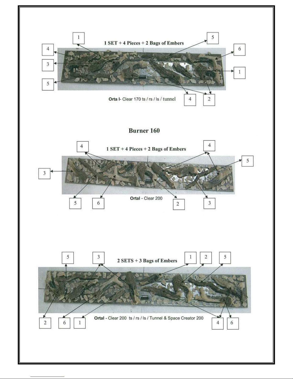
English Logs
Page 51
51
Ortal Technical Guide December 2015
English Logs
Page 52
52
Ortal Technical Guide December 2015
English Logs
Page 53
53
Ortal Technical Guide December 2015
English Logs
Page 54
54
Ortal Technical Guide December 2015
English Logs
Page 55
55
Ortal Technical Guide December 2015
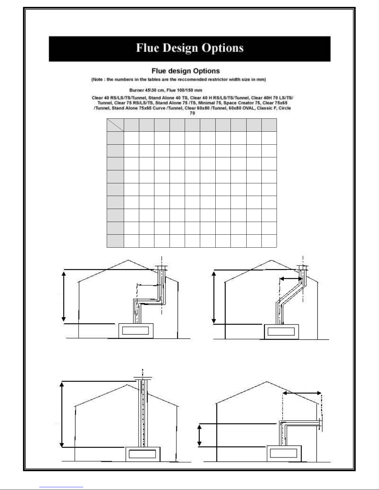
V H
0 1 2 3 4 5 6 7 8 9
1 50 50 50 50 30 30 30 30 0 X
2 50 50 50 50 30 30 30 30 30 0
3 50 50 50 50 30 30 30 30 30 0
4 50 50 50 50 30 30 30 30 30 0
5 50 50 50 50 30 30 30 30 30 0
6 50 50 50 50 30 30 30 30 0 X
7 50 50 50 50 30 30 30 0 X X
8 50 50 50 30 30 30 0 X X X
9 50 50 30 30 30 0 X X X X
H
H
H
V
V
V
V
Key
V = Total vertical height
H = Total horizontal
. . …...distance
X = Not permitted
Page 56
56
Ortal Technical Guide December 2015
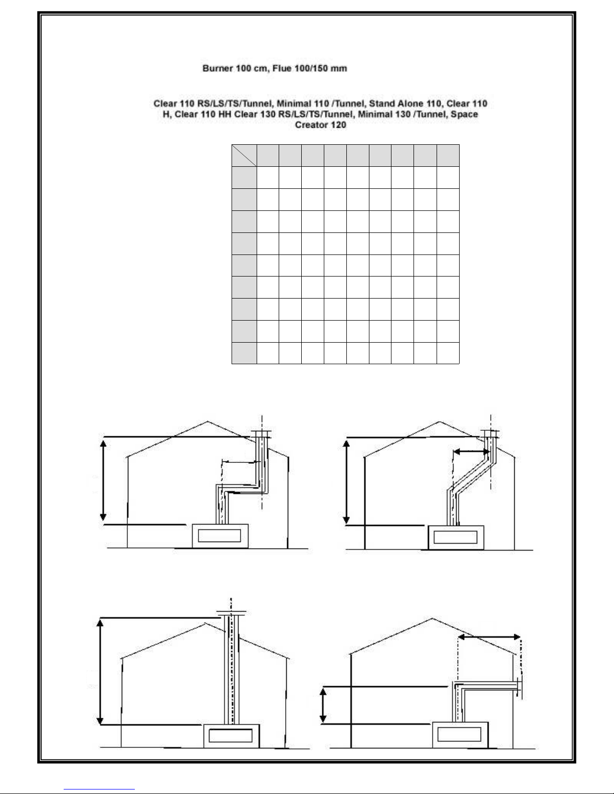
H
H
H
V
V
V
V
Key
V = Total vertical height
H = Total horizontal
. . …...distance
X = Not permitted
V H
0 1 2 3 4 5 6 7 8
1 X 30 30 0 X X X X X
2 50 50 50 50 30 30 30 30 0
3 50 50 50 50 50 30 30 30 0
4 50 50 50 50 50 30 30 30 0
5 50 50 50 50 50 30 30 30 0
6 50 50 50 50 50 30 30 0 X
7 50 50 50 50 30 30 0 X X
8 50 50 50 30 30 0 X X X
9 50 50 30 30 30 0 X X X
For the 110 & 130 models, the 100/150 size flue is
most suited to straight vertical or vertical with up to 3m
horizontal flue arrangements.
For more complex flue arrangements it is
recommended that the 130/200 flue size is used.
To use a 100/150 flue a USVK10 13 reducer will be
required. This must be installed above the USA
adaptor.
Page 57
57
Ortal Technical Guide December 2015
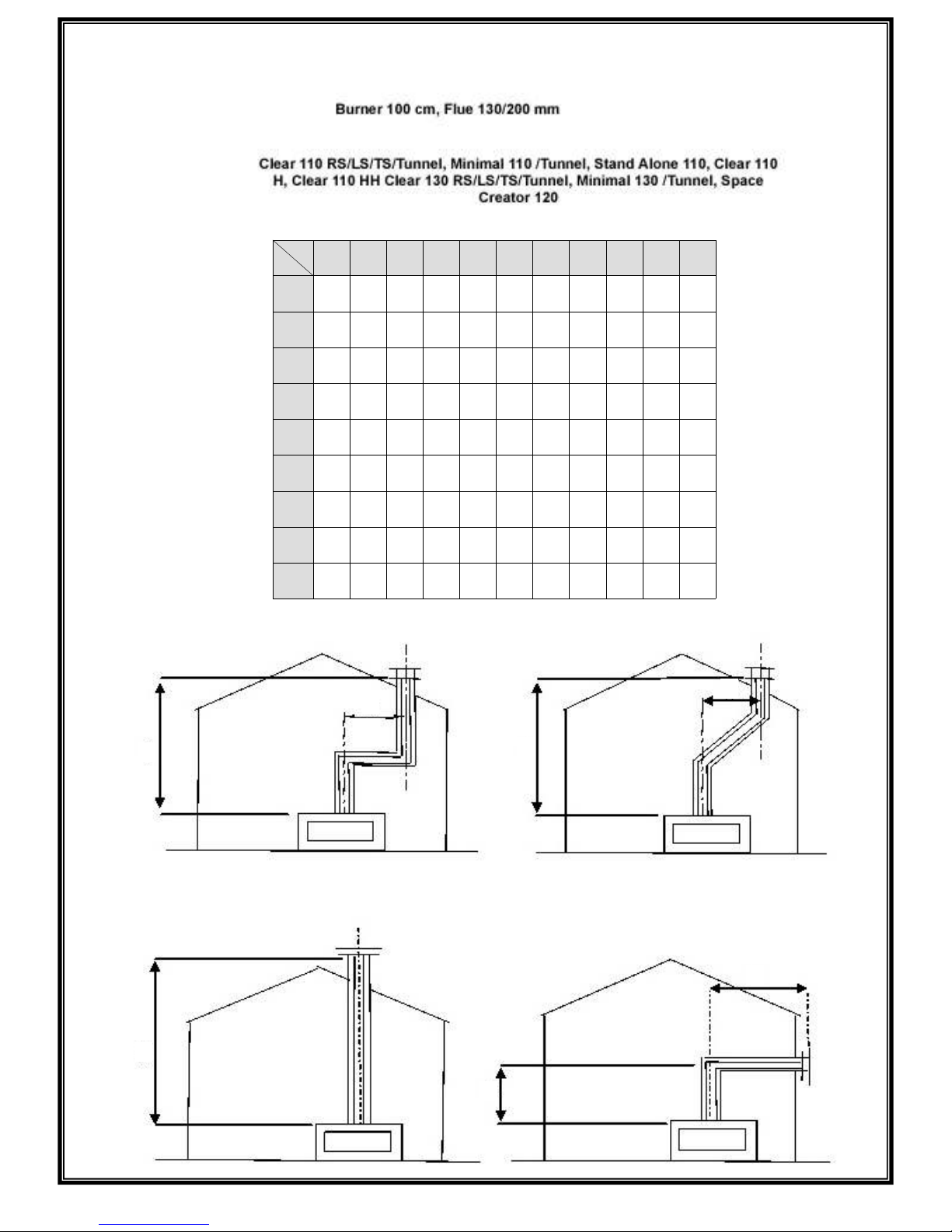
H
H
H
V
V
V
V
Key
V = Total vertical height
H = Total horizontal
. . …...distance
X = Not permitted
V H
0 1 2 3 4 5 6 7 8 9 10
1 70 70 70 50 50 50 30 30 0 0 0
2 85 70 70 70 50 50 50 30 30 30 0
3 85 85 70 70 70 50 50 50 30 30 0
4 85 85 70 70 70 50 50 50 30 30 0
5 85 85 70 70 70 50 50 50 30 30 0
6 70 85 70 70 70 50 50 50 30 30 0
7 70 85 70 70 70 50 50 50 30 30 0
8 70 85 70 70 70 50 50 50 30 30 0
9 70 85 70 70 70 50 50 50 30 30 0
Page 58
58
Ortal Technical Guide December 2015
H
H
H
V
V
V
V
Key
V = Total vertical height
H = Total horizontal
. . …...distance
X = Not permitted
V H
0 1 2 3 4 5 6
1 50 50 50 30 30 30 0
2 70 50 50 30 30 0 0
3 70 50 30 30 30 30 0
4 70 50 30 30 30 30 0
5 70 50 30 30 30 30 0
6 50 30 30 30 30 30 0
7 50 30 30 30 30 30 0
8 50 30 30 30 30 30 0
9 50 30 30 30 30 30 0
Page 59
59
Ortal Technical Guide December 2015
H
H
H
V
V
V
V
Key
V = Total vertical height
H = Total horizontal
. . …...distance
X = Not permitted
V H
0 1 2 3 4 5
1 50 30 30 0 X X
2 50 50 30 30 0 X
3 50 50 30 30 30 0
4 50 50 30 30 30 0
5 50 50 30 30 30 0
6 50 50 30 30 30 0
7 50 50 30 30 30 0
8 50 50 30 30 30 0
9 50 50 30 30 30 0
Page 60
60
Ortal Technical Guide December 2015
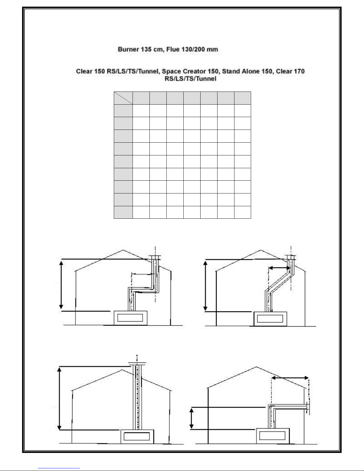
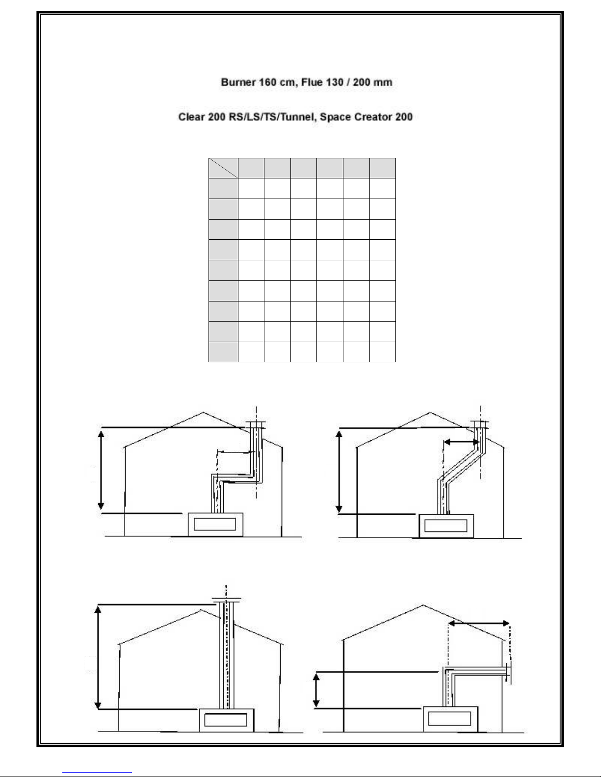
Ortal Flue Design Options
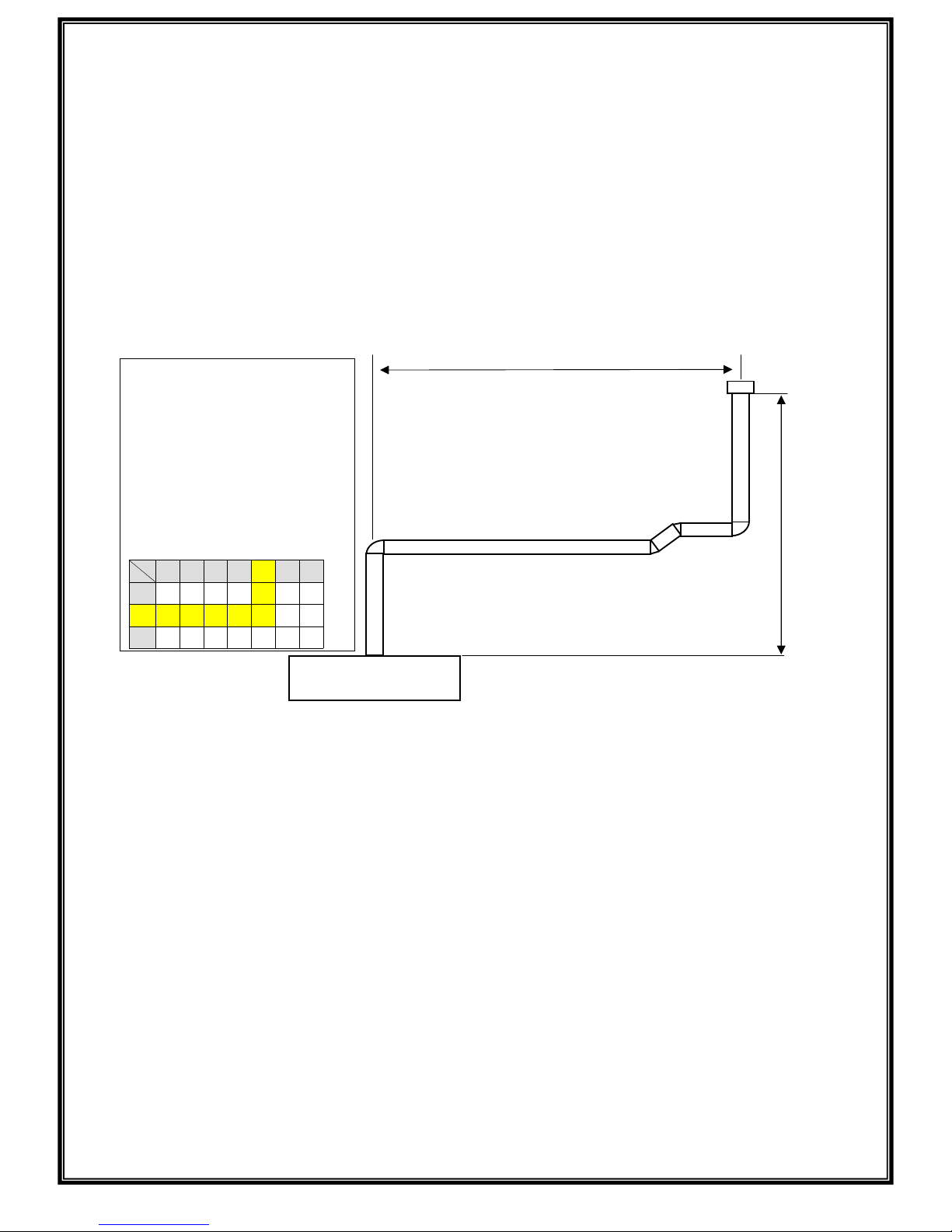
The permitted flue configurations and flue restrictor sizes are as shown in the tables.
V = total vertical height H =total horizontal distance X = configuration not permitted
There should be a minimum of 1m vertical connected to the fire before any bends. The only exception to this is for a vertical flue and
termination, where it is permissible to connect 2 x 45 degree bends directly to a USA adaptor above the fire to offset the flue. The maximum
offset in this condition is a horizontal distance of 0.5m
Additional Bends
It is permitted to add 2 additional bends to form an offset but this reduces the available maximum horizontal distance.
The bends can be 2 x 45 degree*, 2 x 30 degree or 2 x 15 degree bends.
* The bends cannot be put together to form a 90 degree bend.
When referring to the flue/restrictor tables add 0.5m for each additional bend to the measured horizontal flue length to give an equivalent
length, check this is permitted from the tables. See example below.
If the offset is in a horizontal section of the flue it can offset in either horizontal or vertical (upwards only) plane.
90 degree bends are not normally permitted in the horizontal plane i.e. both inlet and outlet ends are horizontal unless specifically approved
through Robeys Technical Department at the planning stage before installation.
Calculation Example
These are typical configurations, however other flue configurations may be permitted on a case by case basis. If you have a special
configuration contact Robeys Technical Department to discuss a solution.
If the flue configuration falls outside the limits then consideration should be given to using a concentric fanned flue system.
Example: Clear 110 model using
130/200mm flue
Total vertical height (V) = 2m
Horizontal (H) = 3m actual + 1m
(2 x 45° bend @ 0.5m per bend)
= 4m total equivalent horizontal
Refer to table,
V =2m with H =4m is permitted with
the use of a 50mm flue restrictor
V = 2m total
H = 3m total
V
H
0 1 2 3 4 5 6
1 70 70 70 50 50 50 30
2 85 70 70 70 50 50 50
3 85 85 70 70 70 50 50
Page 61

61
Ortal Technical Guide December 2015
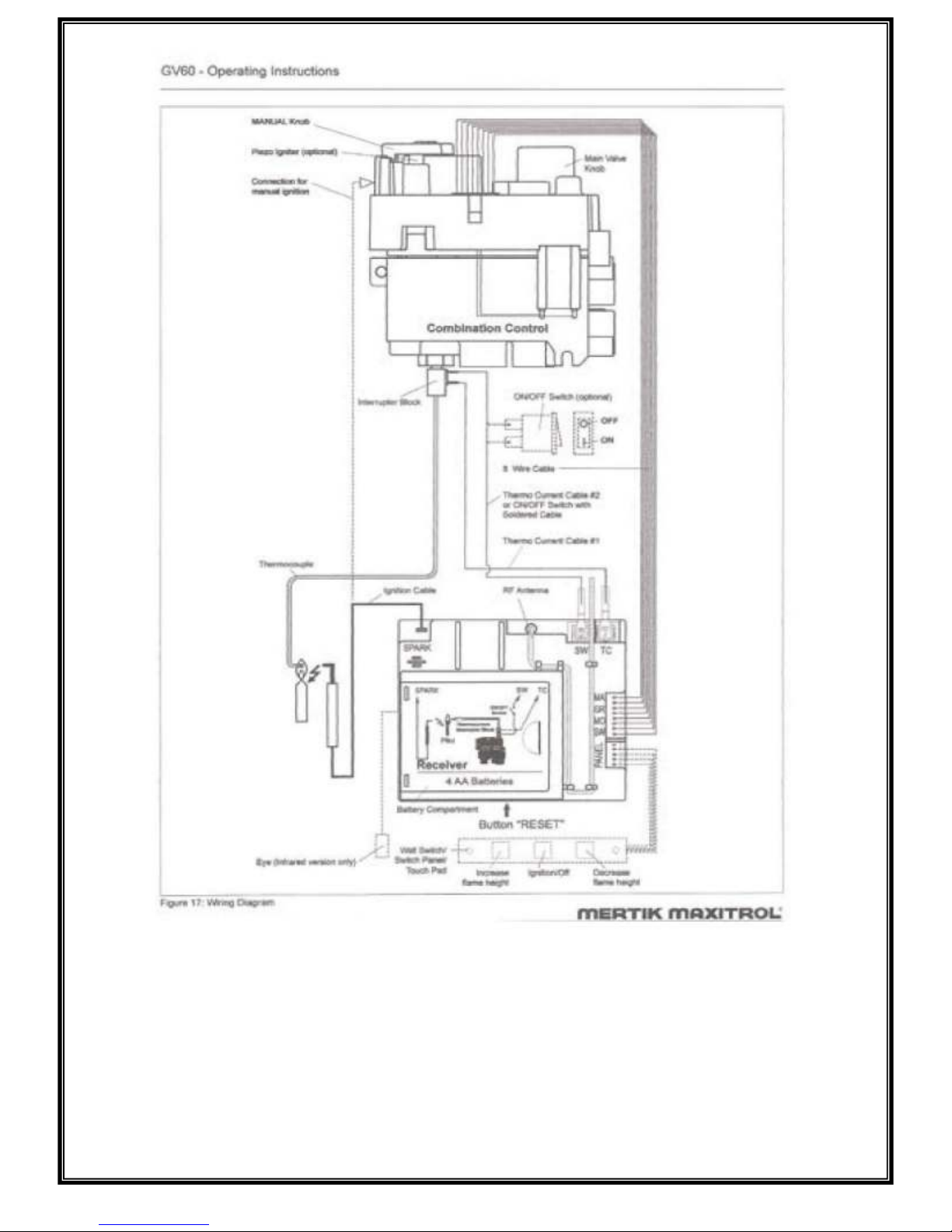
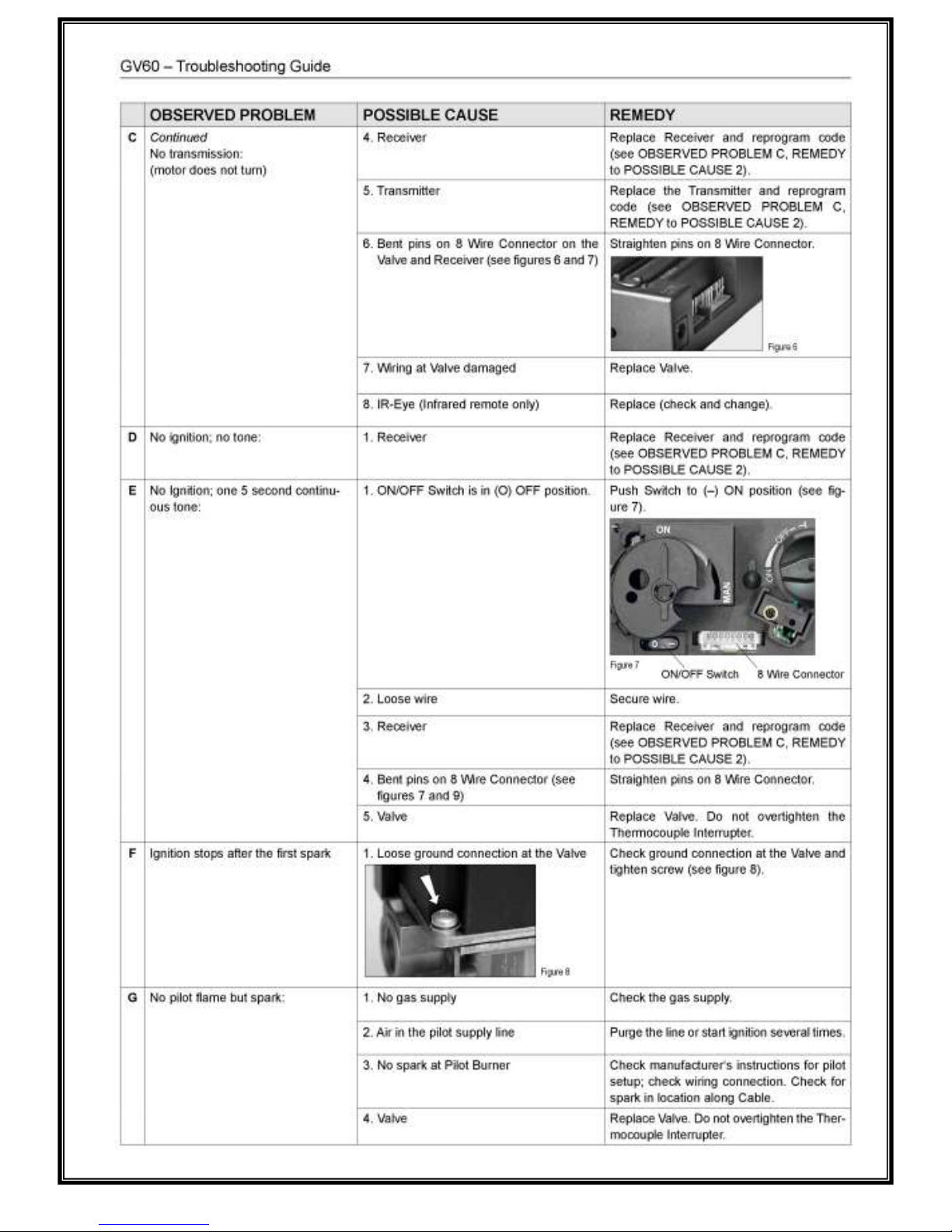
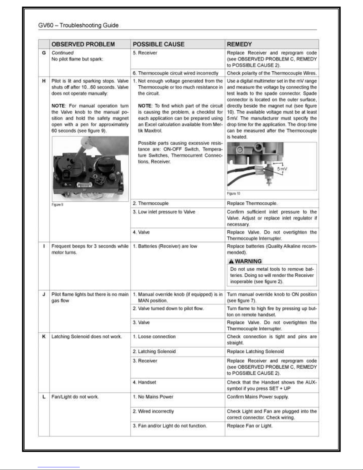
Troubleshooting
The gas pilot will not ignite or stay lit?
Ensure the gas is turned on at the appliance and the meter/cylinder.
Depress the control knob for at least twenty seconds once the pilot is alight to ensure
the operation of the safety thermocouple valve.
Ensure that the pilot injector is not obstructed or blocked and it is free from any dust
or dirt.
Ensure that the thermocouple has not been damaged in transit. This is a very delicate
Electro-magnetic device.
On propane, the cylinder could be empty.
The pilot is not burning or performing correctly?
Ensure the pilot flame is the correct size for the type of gas. The flame should be
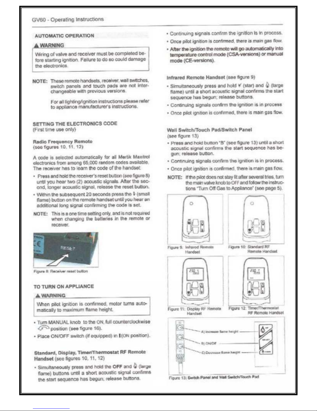
focused on the thermocouple probe.
The pilot flame will have been set correctly in the factory.
The Main Burner does not seem to be burning correctly?
Ensure adequate gas pressure to the appliance. Test pressure by releasing the
pressure test screw and applying a manometer. Ensure adequate volume of gas is
being used. Once the fire is burning on maximum, turn off all other gas appliances in
the house and calculate the fuel being burned from the gas meter.
Make sure that the burner is burning correctly. The flame should be even across the
top of the burner before any coals are placed on top.
Page 62
62
Ortal Technical Guide December 2015
Page 63
63
Ortal Technical Guide December 2015
Page 64
64
Ortal Technical Guide December 2015
Page 65
65
Ortal Technical Guide December 2015
Page 66
66
Ortal Technical Guide December 2015
Page 67
67
Ortal Technical Guide December 2015
Page 68
68
Ortal Technical Guide December 2015
Page 69
69
Ortal Technical Guide December 2015
Page 70
70
Ortal Technical Guide December 2015
Page 71
71
Ortal Technical Guide December 2015
Page 72
72
Ortal Technical Guide December 2015
Page 73

73
Ortal Technical Guide December 2015
Page 74

74
Ortal Technical Guide December 2015
Page 75

75
Ortal Technical Guide December 2015
Page 76
Robeys Ltd
Riverside Works, Goods Road Industrial Estate, Belper, Derbyshire. DE65 1UU
www.robeys.co.uk
 Loading...