

Page 1

USER GUIDE LED LIGHTED CABINET
19.5x27.5x5.5
inch
IF IN DOUBT ABOUT FITTING THIS PRODUCT, PLEASE CONSULT A QUALIFIED ELECTRICIAN
Page 1
Page 2

PLEASE READ THE INSTRUCTIONS BEFORE SET UP AND INSTALLATION
C O M P O N E N T P A R T S A N D F I T T I N G S
IMPORTANT
Suggested Tools:
Cabinet x1
Safety Warning
M04
Hinge cover x 2
(Included in pack)
M07
Screw & Wall plug x 5
(Included in pack)
M05
Wire nut x 3
(Included in pack)
M12
Glass s he lf x 2
(Included in pack)
M13
Mounting bracket x 1
(Included in pack)
M14
L shape bracket x 1
(Included in pack)
M15
Screw x 2
(Included in pack)
Screw driver
Drill
Safety:
• We suggest you spend a short time reading the instruction leaflet.
• Carefully check that you have all the parts before beginning assembly.
• Keep small parts and fittings out of children's reach and keep children well away from construction
area, as the unassembled product contains small parts, which could present a choking hazard.
• We suggest you retain these instructions for future reference.
• This appliance can be used by adults ONLY.
• If the supply cord is damaged, it must be replaced by the manufacturer, its service agent or similarly
qualified persons in order to avoid a hazard.
• Note that this is a hardwired installation and does not come with a power switch. Your electrician
must install the hardwired mirror to an electrical junction box to connect to a room light switch to
turn off or turn on the mirror.
Note that this mirror does not come with a dimmer.
Caution:
• In order to avoid overheating, do not cover the mirror.
• Switch off the mains supply and remove the appropriate fuse or switch off the appropriate circuit
breaker before commencing installation
• Make sure that there is no danger that the cord or extension cord is inadvertently be pulled or cause
anyone to trip when in use.
Page 2
Page 3
Assembly User Instruction/
Please read all instructions ca refully. Before you proceed to insta ll, m ake sure tha t the power su pply is
turned off and remains off until i nstallat ion is compl ete.
Please note that each p art has been a ssigned a nu mber and pro ceed in a numerical order.
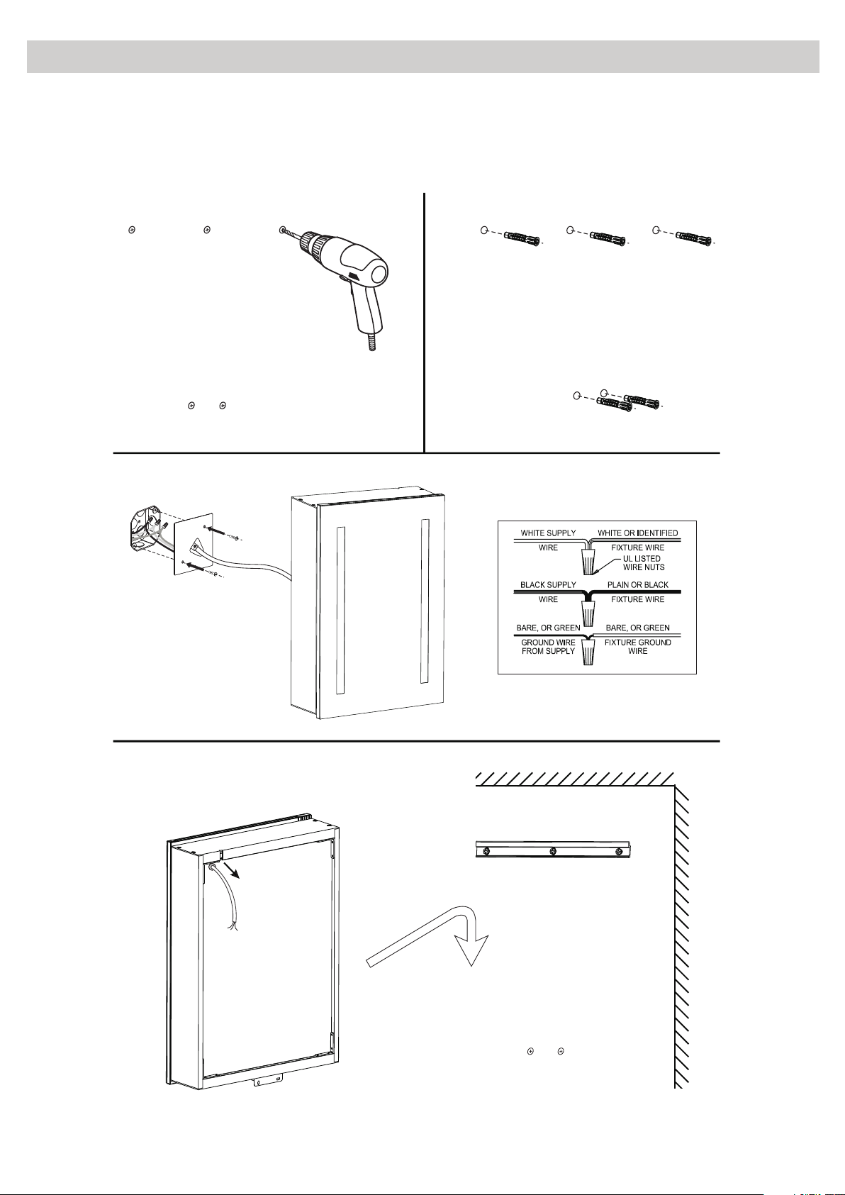
STEP1. Mark the position of the hanging screw.
STEP3. Contact the wires.
STEP4. Hang up the cabinet on the wall
STEP2. Fix the screw.
M13
Cable outlet
Page 3
Page 4

Assembly User Instruction/
Door Adjustment
Hinge Adjustment
Tur n the assig ned screw clo ckwise ca n move
the mi rror door tow ards the ca binet;
Tur n the assig ned screw cou nterclo ckwise
can mo ve the door awa y the cabin et.
Hinge cover
Tur n the assig ned screw clo ckwise ca n move
the mi rror door rig ht;
Tur n the assig ned screw cou nterclo ckwise can
move t he door left.
Fixing Glass Shelf Brackets
Fixing the gla ss shelves Adjusting th e glass shelves
Loosen the rubber
plugs of the glass
shelf bracket, then
put the glass shelf
into the brackets,
tighten the plugs to
fix the shelf.
Notes:
Be careful not to over
loosen screw
If the square screw nut lost,
you could find spares in
fixings bag.
M04
.
M15
Screw L sha pe b ra ck et i nt o pl ac e on t he w al l
and into the base of the cabinet. But do not
screw too tight for the base.
Page 4
M14
Tips: If t he cabinet w as fitted well with
mounting bracket (M 13),no mov ement
left& right or a way& towards th e wall,it
is suggested not to fit t he L shape
bracket (M14).
Page 5

Installation Dimensions:
C
B
A
D D
A(inch) B(inch) C(inch)
19.5
27.5
Page 5
5.5
D(inch)
5.1
 Loading...