

Page 1
PRIVILEGE SERIES
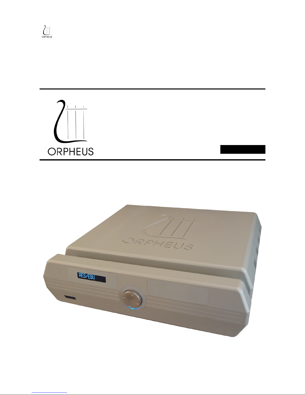
D/A CONVERTER
User manual
1/16
Page 2

Table of Contents
Introduction..........................................................................................................................................3
Contact.............................................................................................................................................3
Document overview.........................................................................................................................3
FRONT PANEL...................................................................................................................................5
REAR PANEL......................................................................................................................................6
CONNECTIONS..................................................................................................................................7
DISPLAY AND MENU STRUCTURE..............................................................................................8
QUICK GUIDE...............................................................................................................................8
1. START UP DISPLAY.................................................................................................................9
2. MAIN SCREEN .........................................................................................................................9
3. STANDBY MODE....................................................................................................................10
4. INPUT NAME SETTING.........................................................................................................10
5. PHASE SELECTION................................................................................................................11
6. LOCK STATUS........................................................................................................................12
7. RING LEDS...............................................................................................................................12
8. DISPLAY...................................................................................................................................12
9. NIGHT MODE..........................................................................................................................13
10. PREFERENCES......................................................................................................................13
SPECIFICATIONS............................................................................................................................14
2/16
Page 3

Introduction
Contact
ORPHEUS MEDIA SARL
Avenue des Sciences 3
1400 Yverdon-les-Bains
Phone : +41 24 423 9088
Fax : +41 24 424 9089
Document overview
This document is the user manual for the Orpheus Media Privilege series D/A Converter.
3/16
Page 4

UNPACKING
First check and identify the contents of your preamplifier package, as listed below:
● D/A Converter
● CD User manual
Read this before operating your unit
● Please read this manual carefully, to assure proper operation and the possible performance.
● Switch off the unit before connecting or disconnecting any input or output cables.
● Do not touch the inner pins of rear panel connectors, electrostatic discharge may cause permanent
damage to the unit.
● Choose the installation location for the unit carefully. Avoid placing it in direct sunlight or close to a
source of heat. Avoid also locations subject to vibration and excessive dust, heat, cold or moisture.
● To reduce the risk of fire or electric shock, do not expose the unit to rain or moisture.
● Do not use force when operating switches, knobs and other controls.
● Do not open the chassis or attempt to male repairs by yourself, as this may result in damage to the
unit or electrical shock. If a foreign object should get into the unit, contact your local dealer.
● When planning not to use the unit for a long period of time, it is advisable to disconnect the power
plug from the wall outlet.
● The power switch does not disconnect the complete unit form the main line.
● To prevent lightning damage, disconnect the power plug when there is an electrical storm.
● When moving the unit, be sure to first disconnect the power plug and all wires connected from the
unit to other equipment.
● When disconnecting the power plus from the wall outlet, always pull directly on the plug, never pill
the cord itself.
● Do not attempt to clean this unit with water or chemical solvents, as this may damage the unit or the
finish. Use a clean, dry cloth.
● Keep this manual in a safe place for future reference.
4/16
Page 5
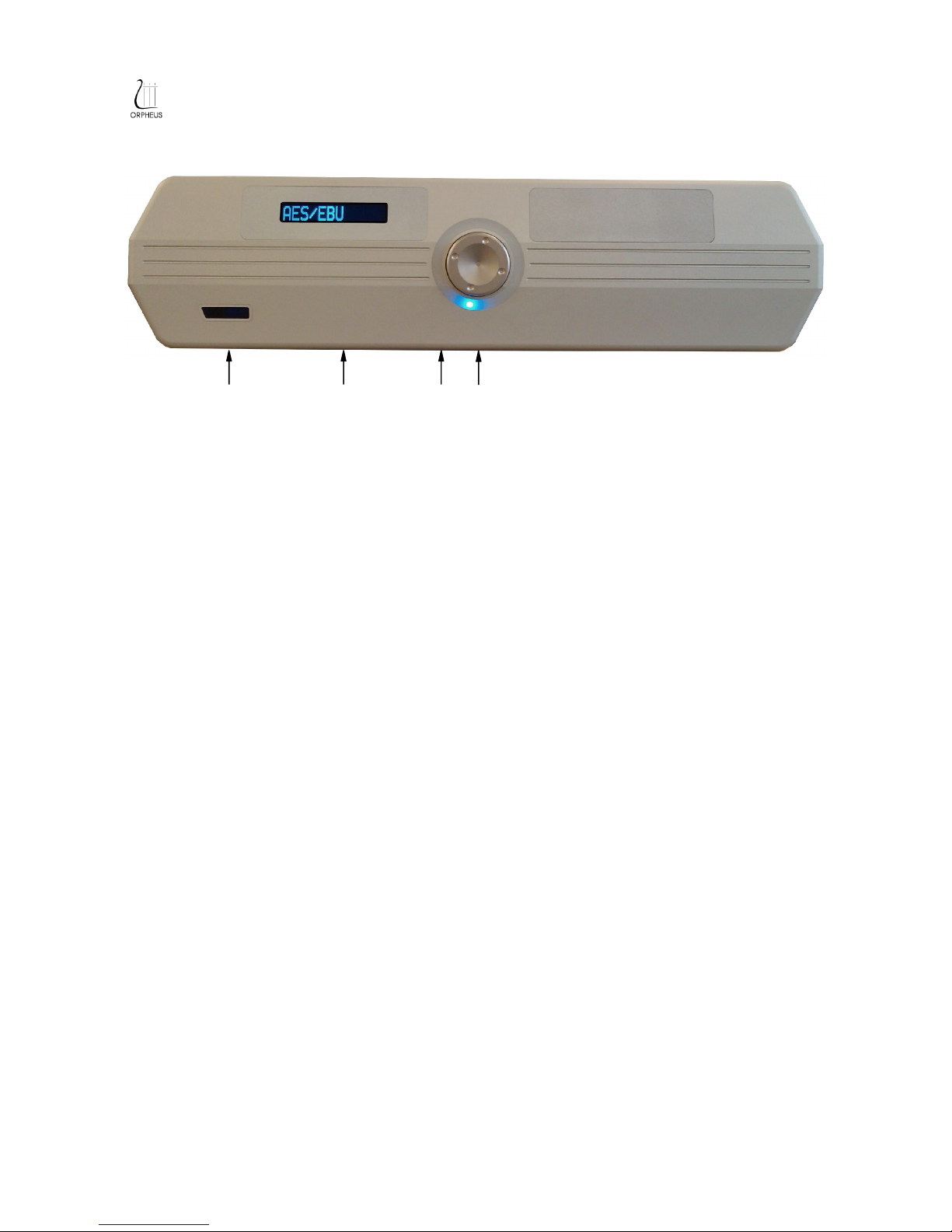
FRONT PANEL
INFRARED REMOTE CONTROL SENSOR
Receives signals from the remote control transmitter.
Compatible with all Orpheus remontes controls transmitter.
DISPLAY
Displays the input selection, as well as the setup menus.
POWER
Lights red when the unit is in standby mode.
Lights red blink when the unit is switching on during 3 secondes and when it is in wake up.
CONTROL
Used for choosing digital input format and menu navigation as well as unit setup.
Turn to right and Turn to Left
Used for increasing, decreasing or choosing values, for instance, while change adjusting volume
levels, dimming the display renaming inputs.
Press on the button to enter in setup.
5/16
Page 6
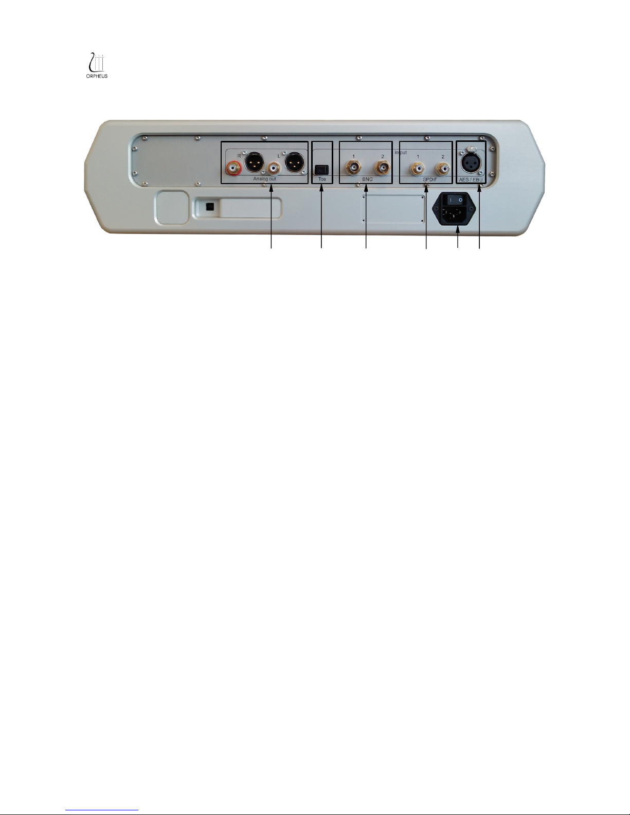
REAR PANEL
OUTPUTS
Analogue balanced right and left channel outputs on XLR connectors. Unbalanced right and
left channel outputs on RCA connectors.
➁ INPUT TOSLINK FORMAT
Digital data stream input using an optical connector for TOSLINK format.
➂ INPUT BNC FORMAT
Digital data stream inputs using two independent connectors (BNC 1 and 2) for BNC format.
➃ INPUT S/PDIF FORMAT
Digital data stream inputs using two independent RCA connectors (S/PDIF 1 and 2) for
S/PDIF format.
➄ POWER SUPPLY & POWER SWITCH
Power cord connection and main power switch
➅ INPUT AES/EBU FORMAT
Digital data stream inputs using two independent RCA connectors (S/PDIF 1 and 2) for
S/PDIF format.
6/16
Page 7
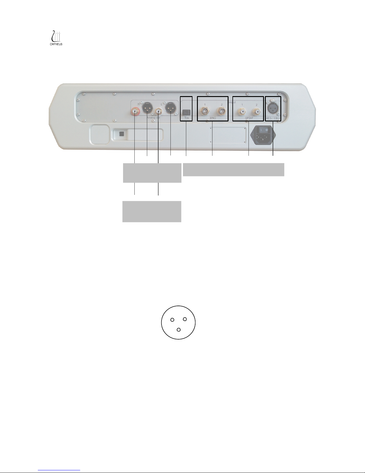
CONNECTIONS
R : right channel
L : left channel
A : AES/EBU
S : S/PDIF
B : BNC
T : TOSLINK
XLR OUTPUT CONNECTOR
Pin 1 : ground
Pin 2 : signal in phase
Pin 3 : signal out of phase
The balanced analogue output is not a floating output. Do not connect pin 3 of the connector to
ground.
If you wish to wire the balanced output to an unbalanced input (with RCA connector), connect pin 1
to ground and pin 2 to signal, and make sure pin 3 is not used.
7/16
Digital data stream inputs from CD drive /
player or other s ource with digital output.
S
R
L
B
R L T
Unbalanced analogue
stereo output to preamp
or integrated am p.
Balanced analogue
stereo output to preamp
or integrated am p.
A
1
2
3
Page 8
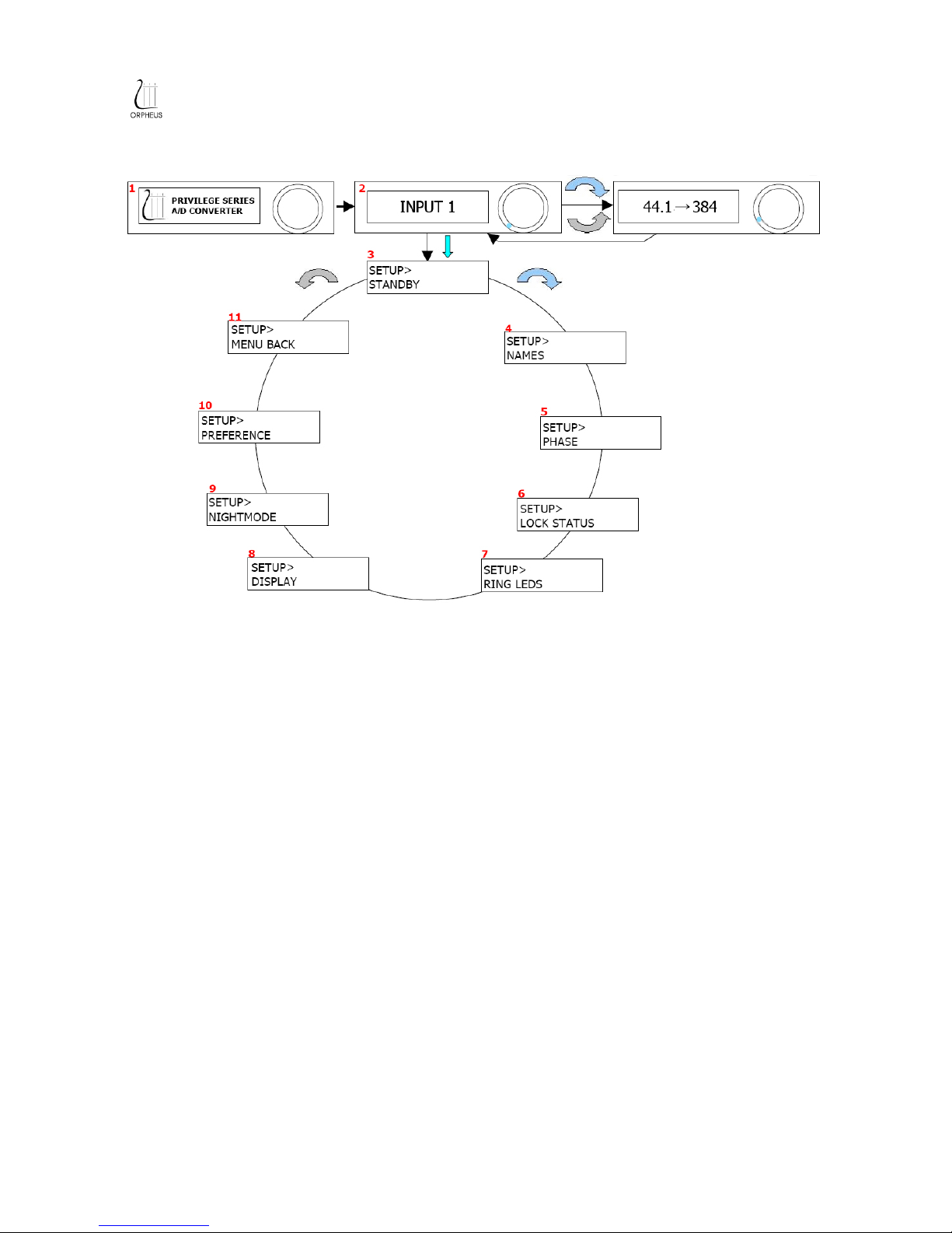
DISPLAY AND MENU STRUCTURE
SETUP AND OPERATIONS
QUICK GUIDE
POWER ON
Flip the main power switch on the lefthand side of the rear panel from 0 to 1.
MAIN SCREEN
After switching on the unit, the display windows shows the start up screen shortly. It then switches
to the default screen which shows input selection for listening.
CHOOSING AN INPUT
Too choose between inputs, turn to right or left the button until the desired input channel is
displayed.
GOING INTO STANDBY
Press the button twice.
LOST? RELAX...
Let the system return to the main screen automatically.
After approximately 10 seconds of control button inactivity the display returns to the previous
menus, and finally to the main screen.
8/16
Page 9
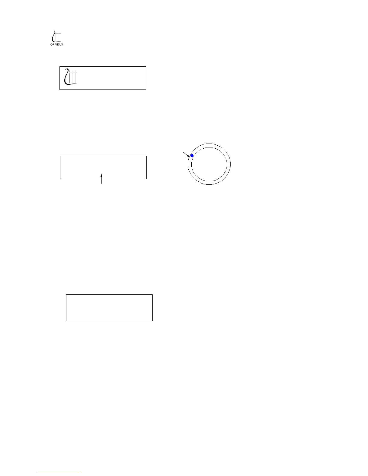
1. START UP DISPLAY
The start up display is shown approximatively 3 seconds when main power is switched on.
It is then replaced by the main screen.
2. MAIN SCREEN
The main screen is the default display during normal operation.
It shows the name of the digital input format selected.
To choose between input formats turn left or right until the desired input format is diplayed.
Options :
● AES/EBU
● SPDIF 1 or 2
● BNC 1 or 2
● TOSLINK
Select between the various options according to your digital source and the connection
established.
UPSAMPLING
When selecting a new source, the display shows the upsampling details. The sampling rate
conversion to the high definition signal which is then converted to the analogue domain is shown in
kHz and is displayed for approx. 2 seconds upon successful lock on to the data stream of the
stream of the chosen digital input format.
Hereafter the display returns to default main screen.
If the system has not been able to lock on to the data stream of the chosen input the display shows
NO LOCK.
NO PCM indicated that a non linear PCM data stream is received form for example a DTS CD.
9/16
SPDIF 1
REFERENCE SERIES
DA CONVERTER
Input selected
Input selected
44.1 → 384
Page 10
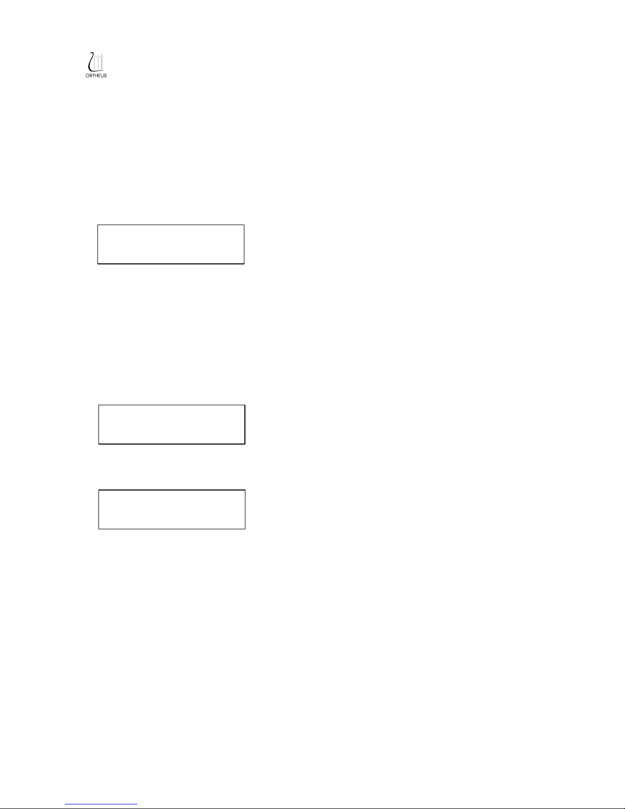
SETUP MENU
From main screen press on the button to enter setup menu.
To choose between the setup menu options turn to right or left with the button until the desired
option is displayed.
3. STANDBY MODE
Pressing on the button the unit in to standby mode.
Pressing any navigation button resumes normal operations.
4. INPUT NAME SETTING
To enter name setting press on the button.
INPUT SELECTION
Select the input that should be renamed by turning to right or left until the chosen input is
displayed. Press on the button to confirm
10/16
SETUP>
NAME
SETUP>NAME>
SPDIF 1
SETUP>
STANDBY
Page 11
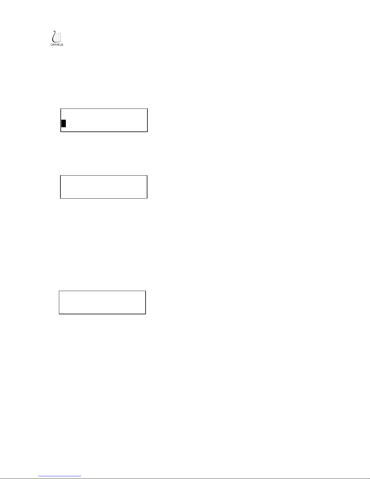
RENAMING
Each input can have any individually defined name. The name can be a word with a combination of
up 10 letters or numbers.
MOVING CURSOR
Turn to right or left to switch from one position to the other.
Press on the button to select the position to change the character.
CHANGING CHARACTERS
Turn to left or right to change the value.
Characters A to Z and 0 to 9, as well as space, are available.
Press the button to confirm the choice.
Wait 10 seconds to confirm the new input name.
5. PHASE SELECTION
To enter phase selection mode press the button.
This function gives to possibility to select phase. Normal mode gives the natural perspective of
music. Inversion mode changes te absolute phase by 180°
Options:
● NORMAL
● INVERSION
To select an input turn to left or right until the chosen phase is displayed.
Press on the button to confirm.
11/16
SETUP>NAME>SPDIF1>
SPDIF 1
SETUP>NAME>SPDIF 1>
TPDIF 1
SETUP>
PHASE
Page 12
6. LOCK STATUS
To enter LOCK STATUS mode press on the button.
This function gives the possibility to enable or disable the Upsampling details (lock status) .
When this function is enable, the upsampling detail is show at every changement of status.
To select an input turn to left or right until the chosen lock status is displayed.
7. RING LEDS
To enter RING LEDS mode press the button.
The leds brightness can be adjusted from 100% to 12.5% in 12.5% steps.
To increase or decrease the value turn to right or left.
Press on the button to select.
8. DISPLAY
To enter display mode press the button.
The display lighting can be adjusted from 100% to 20% in 25% steps.
To increase or decrease the value turn to right or left.
Press on the button to select.
12/16
SETUP>
LOCK STATUS
SETUP>
RING LEDS
SETUP>
DISPLAY
Page 13

9. NIGHT MODE
To enter night mode press on the button.
When night mode is in position ON the display turns off automatically approx. 3 seconds after
pressing any control button.
The unit is still operation and the display lighting is reactivated by pressing any control button.
To set night mode turn to right or left until the chosen mode is displayed.
Press on the button to confirm.
10. PREFERENCES
The various parameter setings allow personalized unit configuration. It is possible to restore
previously stored settings as well as to call back the initial factory settings.
Menu SAVE saves the current setup, it is advisable to save any configuration through menu SAVE
prior to switching off the unit. Menu RESET restores the previously stored setup and menu
FACTORY SETTINGS restores the default factory settings.
To access this menu from main screen, press on the button, turn to left twice times and press.
Turn to right once, twice, three or four times to access menus SAVE, RESET, FACTORY
SETTING or SOFTWARE REVISION respectively. Press on the button to enter your choice. In the
case of RESET and FACTORY SETTINGS press on the button again to confirm.
FACTORY SETTING has fallowing values.
Names : SPDIF 1 and 2, AES/EBU, BNC 1 and 2, TOSLINK
Phase : NORMAL
Lock Status : ON
DISPLAY : 100%
LEDS : 100%
Night Mode : OFF
13/16
SETUP>
NIGHTMODE
SETUP>
PREFERENCES
Page 14

SPECIFICATIONS
D/A Converter is a 2 channel 24/384kHz upsampler and digital to analogue conversion unit.
D/A Converter features software based Q5™ sample rate conversion technology. Each incoming
data stream is converted into a high definition 24bit/384kHz signal prior to being converted to the
analogue domain.
The complexity of the analogue reconstruction filter is significantly reduced by using a 384kHz
sampling rate. This result in near perfect phase linearity and soundstage quality.
Technical data
Digital input : one S/PIDF, 75 Ohm, 0.5 V, on RCA connector and
one AES/EBU, 100 Ohm, 5 V, on XLR connector
Analogue output : either balanced, 4.7 Vrms, on XLR connectors or
unbalanced, 2.35 Vrms, on RCA connectors
Impedance : 75 Ohm
24 bit / 44.1kHz input signal :
Harmonic distortion (TH+N) : -110dBr @ 0dB FS
Dynamic (THD+N @ -60 dB FS) : 121 dBr
Signal to noise 20 Hz to 22kHz :
3.2 µV @ 4.7 Vrms balanced
1.6 µV @ 2.35 Vrms unbalanced
14/16
Page 15

COMMENTS
Constructive feedback is always welcome.
Please feel free to forward us your comments at the address listed on last page or to your local
dealer or distributor.
TECHNOLOGY & DESIGN
The unit has been entirely manufactured and assembled in Switzerland; conceived by ORPHEUS
Media sàrl.
IMPORTANT NOTICE
ORPHEUS Media sàrl reserve the right to make changes to their products or discontinue any
product or service without notice. Adequate operating safeguards must be used to minimize
hazards. Reproduction of user manual information is permissible only if it is without alteration and
is accompanied by all relevant conditions, limitations and notices. Source must be clearly identified
when reproducing user manual information.
15/16
Page 16

LIMITED WARRANTY CERTIFICATE
ORPHEUS Media guarantees that the product described below is free of defective material and
workmanship. The warranty extends for a period of one year form original purchase date, but at
maximum two years form manufacturing date. ORPHEUS Media agrees to repair or replace
defective parts or the complete unit at its option, provided that the equipment is returned
exclusively to the original dealer.
This limited warranty is contingent upon proper and normal use and installation, and does not
cover damage due to external causes, including but not limited to, accident, careless handling,
improper installation or connection, problems with electrical power, electrical contact or electrical
grounding, liquids, chemicals, oxidation, corrosion, exposure to the elements, service or repair not
authorized by ORPHEUS Media, usage not in accordance with product instructions, failure to
perform required preventive maintenance, and problems caused by use of parts and components
not supplied or authorized by ORPHEUS Media. Removing, altering, tampering with serial number
voids the limited warranty. The limited warranty does not extend to or include consequential
damage, and does not apply in any case for damage occurring during shipping or installation.
ORPHEUS Media Sàrl, Av. Des Sciences 3, 1400 Yverdon-les-Bains, Switzerland
ORPHEUS Media Sàrl – August 2009 – rev.1
Strategy Manager Technical Manager
Tallant Fabien Schlaepfer Julien
Model PRIVILEGE SERIES - PREAMPLIFIER Serial Number
16/16
 Loading...