

Page 1

SafeLink R10 SRS
Survivor Recovery System
USER MANUAL
Page 2

Page 3
This manual is applicable to the SafeLink R10 SRS AIS MOBs.
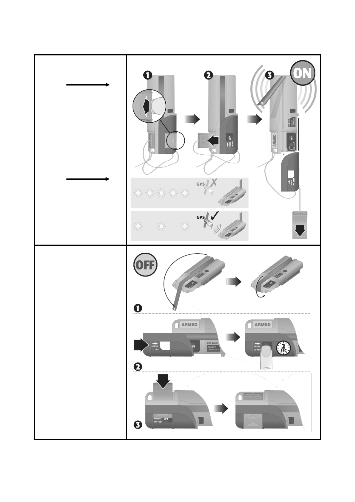
To arm
Armer
Armar
To turn on
Activer
Activar
Fold the antenna back
HOLD
Fit the arming tab back
Repliez l’antenne
MAINTENEZ
Remettre la languette en
place
Doble la antena
MANTENER
Reensamble la lengüeta
de armamento
Page 4

TABLE OF CONTENTS
INTRODUCTION ........................................................................................ 1
1
2 SAFETY NOTICES ....................................................................................... 1
3 LIFEJACKET ATTACHMENT ........................................................................ 2
4 CAUTIONS ................................................................................................ 3
5 SELF TEST ................................................................................................. 4
6 SPECIFICATION ......................................................................................... 5
7 END OF LIFE STATEMENT ......................................................................... 6
8 TRANSPORTATION .................................................................................... 6
9 EU DECLARATION OF CONFORMITY ......................................................... 6
TABLE DES MATIERES
1.
INTRODUCTION ........................................................................................ 7
2. CONSIGNES DE SÉCURITÉ ......................................................................... 7
3. FIXATION SUR LE GILET DE SAUVETAGE ................................................... 8
4. ATTENTION ............................................................................................... 9
5. AUTO-DIAGNOSTIC ................................................................................. 10
6. CARACTÉRISTIQUES TECHNIQUES .......................................................... 11
7. CONDITIONS DE MISE AU REBUT ............................................................ 12
8. TRANSPORT ............................................................................................ 12
9. DÉCLARATION DE CONFORMITÉ CE ........................................................ 12
TABLA DE MATERIAS
1.
INTRODUCCIÓN ...................................................................................... 13
2. AVISOS DE SEGURIDAD ........................................................................... 13
3. SUJECION DEL CHALECO SALVAVIDAS .................................................... 14
4. PRECAUCIONES ...................................................................................... 15
5. AUTOCOMPROBACIÓN ........................................................................... 15
6. ESPECIFICACIONES ................................................................................. 17
7. DECLARACIÓN DE CADUCIDAD ............................................................... 18
8. TRANSPORTE .......................................................................................... 18
9. DECLARACIÓN DE CONFORMIDAD CE .................................................... 18
Page 5

INHALTSVERZEICHNIS
1.
VORWORT .............................................................................................. 19
2. SICHERHEITSHINWEISE ........................................................................... 19
3. BEFESTIGUNG AN DER SCHWIMMEWESTE ............................................. 20
4. SICHERHEITSHINWEISE ........................................................................... 21
5. SELBSTTEST ............................................................................................ 22
6. TECHNISCHE DATEN ............................................................................... 23
7. ENTSORGUNG ........................................................................................ 24
8. TRANSPORT ............................................................................................ 24
9. EU - KONFORMITATSERKLARUNG .......................................................... 24
DISCLAIMER ..................................................................................................... 25
LIMITATION DE RESPONSABILITE ..................................................................... 25
DESCARGO DE RESPONSABILIDAD.................................................................... 25
Page 6
1 INTRODUCTION
The SafeLink R10 SRS is a personal portable AIS device. Lightweight and compact, it
is designed to be carried by all crew members and should be mounted on a
lifejacket.
When triggered, the R10 SRS transmits GPS position information to all AIS-equipped
vessels and stations within range to assist fast recovery in distress situations. Each
unit is encoded with a unique serialised ID to ensure all crew are recovered and
accounted for. To further assist in recovery, the R10 also features an ultra-bright LED
beacon. The lithium power cell offers a minimum 24 h continuous operation and a 7
year battery storage life.
2 SAFETY NOTICES
Please take time to read this manual fully before using the SafeLink R10 as it contains
important information regarding the correct use and maintenance of the product.
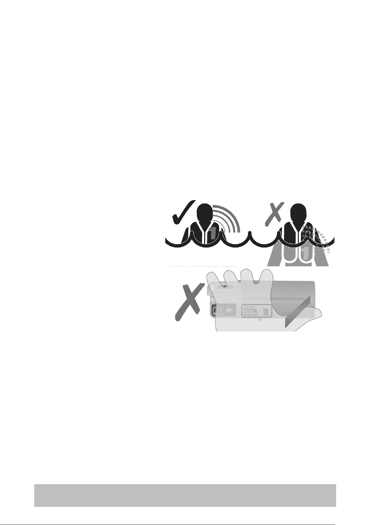
When mounting on a lifejacket,
ensure the R10 remains on a part
which stays out of the water, as
direct contact to the sea will
severely reduce the transmission
range.
Ensure that the blue area marked
"GPS Zone" is not obstructed or
covered in any way and always has
a clear view of the sky.
It is recommended that the Short
Test is performed monthly. Return the R10 to a service centre for battery replacement
if battery level is low.
Confirm that the battery expiry date shown is in date for the duration of intended use.
EN 1 X
Page 7
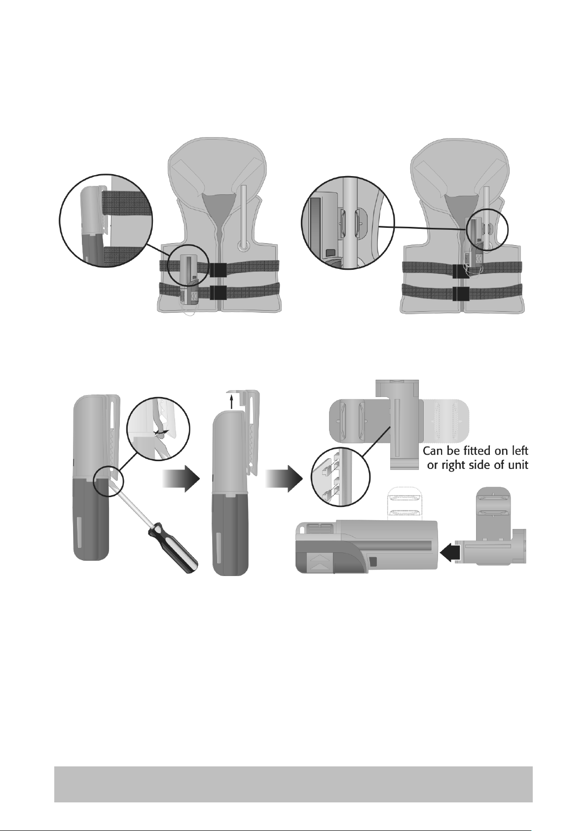
3 LIFEJACKET ATTACHMENT
The R10 can be attached to the lifejacket using either the webbing clip or oral tube
attachment.
FITTING ORAL TUBE CLIP
2 ENX
Page 8

4 CAUTIONS
ACTIVATE ONLY IN AN EMERGENCY
• This product is designed for use with an AIS receiver and is not a substitute for a
PLB or EPIRB.
• This beacon is intended for use within the maritime environment where permitted
by national administrations. When activated, it transmits a digital alert message to
any vessel or shore station in radio range which is equipped with an AIS receiver.
Deliberate misuse of the device could result in a penalty.
• Product and battery pack contain no user-serviceable parts. Do not dismantle.
• Spring action antenna. Mount and deploy in such a way as to avoid eye injury.
• Contains lithium batteries. Do not incinerate, puncture, deform, short-circuit or
recharge.
• Avoid cleaning the unit with chemical solvents as this may damage the case
material.
• Radio Licensing. This product is a radio transmitter. Some administrations may
require that the user holds a valid radio license to cover its ownership and use.
• This product emits low levels of radio frequency energy during operation. Avoid
handling the antenna once activated.
• As AIS beacons are still very new, not all small-craft chart plotters with AIS show
the correct SART icon as recommended by the IMO. As a
minimum, they will show the same icon as used for other craft
- normally an arrow. In addition, user settings generally allow
you to configure the display to show the serial number, which
in AIS Beacons will always begin with 97. This will differentiate
AIS Beacons (SARTs) from normal AIS targets. If in doubt, check
with your plotter manufacturer how they display SARTs on screen.
• False alarm: If the unit has been accidentally activated contact the coastguard.
• Storage and Handling: Magnetic switch, take care not to stow
close to strong magnetic sources such as Loudspeakers,
electric motors or DC power cables
EN 3 X
Page 9
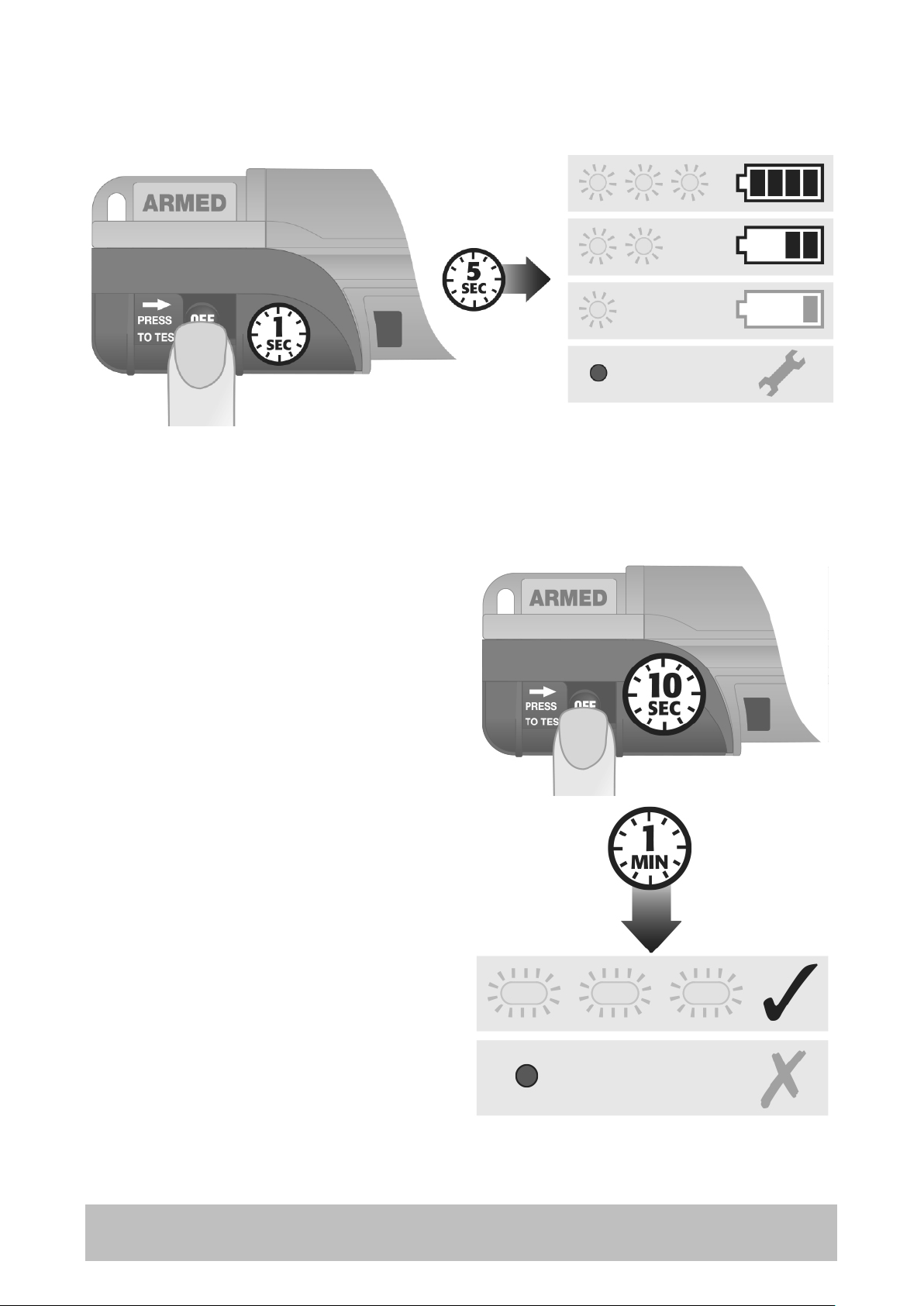
5 SELF TEST
Quick system check and battery life test:
LONG TEST
Full system check including GPS activation and live test message transmission.
• Requires a clear view of the sky.
• Ensure GPS Zone on unit is not
obstructed.
• Perform away from busy sea areas
where the test transmission could
confuse other AIS users.
• Press and hold OFF for 10 s until 2 s
long flash.
• Unit will flash every 1 s until GPS fix is
achieved.
• After 1 minute a SART test message
is sent, which will be visible to all AIS
systems within range.
• At the end of the test, 3 long flashes
indicate the test is successful. No
flashes indicates the test has failed.
• If the Long Test fails, check the GPS
Zone has a clear view of the sky and
re-test. If the test fails a second time,
return the unit to the service centre.
4 ENX
Page 10

6 SPECIFICATION
Standards ................................ EN 303098, EN 301489-1, EN 301489-19, EN 303413,
........................................................................................... RTCM11901-1, AS 4869.4
Sealing depth .................................................................... Immersion to 5 m (16.4 ft)
Operating temperature ................................................. -20 to + 55 °C (-4 to + 131 °F)
Storage temperature .................................................... -30 to +70 °C (-22 to+ 158 °F)
Battery type ............................................................................... Lithium Manganese
Transmit ...................................................................................................... 24 hours
Battery life (storage) ....................................................................................... 7 years
Transmitter Frequency ....................................................... 161.975 & 162.025 MHz
Transmitter Power ................................................................................ 2 W nominal
AIS Messages Transmitted ............... Message 1 (UID, GPS position, SOG, COG, UTC),
................................................................... Message 14 (MOB ACTIVE or MOB TEST)
First Transmission ............................................................. After 15 seconds (No GPS)
Range ......................... 4 nm typical, with AIS receiver antenna > 5 m above sea level
ID Number ................................................................................ Factory Programmed
GPS Type ............................................................ 50 channel, ceramic patch antenna
GPS Position Update ............................................................................ Every minute
Size (D x W x L) ............................................ 27 x 47 x 124 mm (1.06 x 1.85 x 4.88 in)
Weight ................................................................................................ 120 g (4.23 oz)
Standard Compass Safe Distance ............................................... 0.1-1° at 30 cm (1 ft)
Warranty .................................................... 1 year (+1 years with online registration)
EN 5 X
Page 11

7 END OF LIFE STATEMENT
At the end of its life, the product must be disposed of according
to local laws and regulations and it must be disposed of
separately from household waste.
The battery should also be removed to prevent false alerts.
Do not incinerate, but take it to a recycling facility.
8 TRANSPORTATION
The product contains a lithium metal battery with a lithium content less than 2 g and
a total net quantity of 0.034 kg. It is classified as dangerous goods for transportation
purposes: Class 9, UN3091, Lithium metal Batteries Contained in Equipment, although
not all restrictions apply.
Transport by air: the product may be carried on a passenger aircraft either as carryon or checked in baggage. If shipped as cargo, the product must be packaged and
shipped via a qualified dangerous goods shipper. Packing instruction P970 Section II
applies.
Transport by sea: The product may be carried in a private vehicle or as carry-on
baggage. If shipped as cargo, the product must be packaged and shipped via a
qualified dangerous goods shipper. Special provision 188 applies.
Transport by road: The transport of dangerous goods regulations do not apply to
items carried in a private vehicle for personal use. Product being transported by
courier/road haulier must be packaged and shipped via a qualified dangerous goods
shipper. Special provision 188 applies.
9 EU DECLARATION OF CONFORMITY
Hereby Orolia Ltd declares that Type Z501 is in compliance with
the essential requirements and other relevant provisions of Radio
Equipment Directive 2014/53/EU. A copy of the full Declaration
of Conformity can be obtained online from:
https://www.mcmurdogroup.com/regulatory_documents_z501
Orolia Ltd hereby declares that all materials, components and products supplied are
in full compliance with RoHS & WEEE directives.
Use of this equipment is subject to restriction of use and / or licensing in the following
EU countries:
6 ENX
Page 12

1. INTRODUCTION
Le SRS SafeLink R10 est une balise personnelle AIS. Légère et compacte, ce système
est conçu pour être porté par tous les membres d'équipage et doit être fixe sur un
gilet de sauvetage.
Une fois déclenchée, la balise R10 émet les données de localisation GPS à tous les
navires équipés AIS et aux stations terrestres a proximité afin qu'ils puissent porter
assistance en situation de détresse. Chaque balise est identifiée par un numéro de
série unique qui permet l'enregistrement et le sauvetage de chaque membre
d'équipage. Pour un sauvetage encore plus efficace, la balise R10 est également
équipée d'un feu de localisation à haute luminosité. La pile au lithium offre une
autonomie de 24 h en continu et une durée de vie de 7 ans.
2. CONSIGNES DE SECURITE
Veuillez prendre le temps de lire l'intégralité du présent manuel avant d'utiliser la
SafeLink R10. Il contient d'importantes informations relatives à l'utilisation et à
l'entretien corrects de cet équipement.
Sur le gilet de sauvetage, assurezvous de fixer la balise sur la partie
émergée de celui-ci, de sorte à
palier à la réduction très
importante de la portée
d'émission qui intervient quand la
balise est en con- tact direct avec
l'eau.
Assurez-vous que la zone bleue
marquée "GPS Zone" n'est ni
obstruée ni masquée d’une
quelconque façon et qu'elle
dispose toujours d'une vision
dégagée du ciel.
Nous vous conseillons d'effectuer un test rapide chaque mois. Renvoyez la balise R10
a un centre de SAV pour le remplacement de la batterie dès que le niveau de charge
de celle-ci est bas.
Vérifiez que la date de péremption indiquée pour la batterie correspond à la durée
d'utilisation prévue.
FR 7 X
Page 13

3. FIXATION SUR LE GILET DE SAUVETAGE
La R10 peut être fixée à un gilet de sauvetage via le clip de fixation sur sangle ou le
clip d'embout buccal.
FIXATION DU CLIP D’EMBOUT BUCCAL
8 FRX
Page 14

4. ATTENTION
ACTIVER LA BALISE EN CAS D’URGENCE UNIQUEMENT
• Cette balise est conçue pour être utilisée en environnement marin, conformément
aux dispositions administratives de chaque pays. Lorsqu'elle est activée, elle émet
un message d'alerte numérique vers tout bateau ou station terrestre à portée
d'émission radio, équipée d'un récepteur AIS.
Toute utilisation abusive de cet équipement peut entrainer des poursuites.
• Cet équipement et son pack batterie ne comprennent aucune pièce remplaçable
par l'utilisateur. Ne démontez pas cet équipement.
• Antenne à déploiement à ressort installez et déployez l'antenne en protégeant vos
yeux.
• Contient des batteries au lithium. Ne pas bruler, perforer, déformer, mettre en
court-circuit ni recharger.
• Ne pas utiliser, de solvants chimiques pour le nettoyage de l’appareil au risque
d’endommager le boitier.
• Licence radio. Cet équipement est un émetteur radio. Certaines administrations
peuvent exiger que l'utilisateur soit détenteur d'un certificat d’operateur radio
valide autorisant sa détention et son utilisation.
• En cours d'utilisation cet équipement émet de faibles niveaux d'énergie
radioélectrique. Evitez de manipuler l'antenne une fois la balise activée.
• Comme les transpondeurs AIS sont encore très récents, l'icône SART recommandée
par l'OMI, n'est pas toujours affichée par les traceurs de cartes pour petites
embarcations. Néanmoins, ces traceurs affichent la même icone que celle
indiquant les autres navires, généralement une flèche. De plus le paramétrage
utilisateur permet généralement de programmer l’affichage
indiquant le numéro de série qui, pour la R10, commence
toujours par 97. C'est ce qui fait la différence entre les Balises
AIS (Transpondeurs) et les cibles AIS normales. En cas de
doute, demandez au fabricant du traceur d’icône SART de
cartes, comment afficher les transpondeurs à l'écran.
• Fausse alarme : contactez immédiatement les autorités maritimes en cas
d’activation accidentelle de la balise.
• Stockage et manutention : Interrupteur magnétique, tenir
éloigné de sources de forts champs magnétiques telles des
haut-parleurs, des moteurs électriques ou des câbles
d'alimentation courant continu.
FR 9 X
Page 15

5. AUTO-DIAGNOSTIC
Test rapide du système et de la batterie :
TEST LONG
Test complet y compris de l’activation du GPS et de l’émission en temps réel d'un
message test.
• Nécessite une vue dégagée du ciel
• Assurez-vous que la zone GPS ne soit
pas masquée ou obstruée.
• A effectuer loin des zones encombrées
au risque de perturber les autres
utilisateurs de systèmes AIS.
• Appuyez pendant 10 secondes sur OFF
jusqu'à émission d'un flash d’une
durée de 2 secondes.
• L'appareil clignote au rythme d'une
fois par seconde jusqu'à l'acquisition
d'un point GPS.
• Après 1 minute, la balise émet un
message test, visible par tous les
systèmes AIS a portée d'émission.
• En fin de séquence, 3 longs flashs
indiquent que le test a été effectue
avec succès. L'absence de flash indique
l'échec du test.
• En cas d'échec du test long, vérifiez que la zone GPS dispose d'une vue dégagée du
ciel et procédez à un nouveau test. En cas de second échec, renvoyez l'appareil au
centre de SAV.
10 FRX
Page 16

6. CARACTERISTIQUES TECHNIQUES
Normes ................................... EN 303098, EN 301489-1, EN 301489-19, EN 303413,
........................................................................................... RTCM11901-1, AS 4869.4
Etanchéité .......................................................................... Immersion à 5 m (16.4 ft)
Température de fonctionnement ..................................... -20 à + 55 °C (-4 à + 131 °F)
Température de stockage ............................................... -30 à +70 °C (-22 à+ 158 °F)
Type de batterie .......................................................................... Lithium Manganèse
Durée d’émission ...................................................................................... 24 heures
Durée de vie de la batterie (stockage) ................................................................ 7 ans
Fréquence d’émission ......................................................... 161.975 & 162.025 MHz
Puissance d’émission ............................................................................ 2 W nominal
Messages AIS émis ........................... Message 1 (UID, position GPS, SOG, COG, UTC),
................................................................... Message 14 (MOB ACTIVE or MOB TEST)
Première émission ..................................... Après 15 secondes (Pas de données GPS)
Portée ................................................................................................ 4 nm standard,
......................... avec antenne de réception AIS > 5 m au-dessus du niveau de la mer
Numéro d’identification ...................................................... Programmation en usine
Type de GPS ................................................ 50 canaux, antenne patch en céramique
Mise à jour de la position GPS ...................................................... Toutes les minutes
Dimensions (P x l x L) .................................. 27 x 47 x 124 mm (1.06 x 1.85 x 4.88 in)
Poids ................................................................................................... 120 g (4.23 oz)
Distance standard de sécurité du compas .................................. 0.1-1° at 30 cm (1 ft)
Garantie .................................................. 1 an (+1 ans avec enregistrement en ligne)
FR 11 X
Page 17

7. CONDITIONS DE MISE AU REBUT
En fin de vie ce produit doit être mis au rebut conformément aux
dispositions légales et règlementaires locales et dans tous les cas,
séparément des ordures ménagères.
La batterie doit être enlevée de la balise pour éviter les fausses
alertes.
N'incinérez pas la batterie mais confiez-la à une déchetterie.
8. TRANSPORT
Ce produit contient une batterie métallique au lithium (quantité de lithium inférieure
à 2 g et poids net total de 0.034 kg). Il relève de la réglementation sur le transport de
marchandise dangereuse pour catégorie Classe 9 : UN3091 Batteries et piles au
lithium métal contenues dans un équipement, mais toutes les restrictions ne sont pas
applicables.
Transport aérien : Ce produit peut être transporté à bord des aéronefs de passagers
en bagage cabine ou en bagage enregistré. Pour le fret aérien, il doit être emballé et
expédié par un transporteur agréé en marchandises dangereuses. L’instruction
d’emballage P970 Section II s’applique.
Transport maritime : Ce produit peut être transporté à bord d’un véhicule privé ou
en bagage à main. Pour le fret, le produit doit être emballé et expédié par un
transporteur agréé en marchandises dangereuses. La Disposition Spéciale 188
s’applique.
Transport routier : La réglementation relative au transport des marchandises
dangereuses ne s'applique pas aux objets transportés dans un véhicule privé à usage
personnel. Pour le fret routier, les produits doivent être emballés et expédiés par un
transporteur agréé en marchandises dangereuses. La Disposition Spéciale 188
s’applique.
9. DECLARATION DE CONFORMITE CE
Orolia Ltd déclare par la présente que cet appareil de type Z501
est conforme aux normes essentielles et autres dispositions
applicables de la directive RED 2014/53/UE. La déclaration de
conformité est disponible en ligne à l'adresse :
https://www.mcmurdogroup.com/regulatory_documents_z501
Orolia Ltd déclare par la présente que tous les matériaux, composants et produits
fournis sont conformes aux directives RoHs et D3E.
L'utilisation de cet appareil requiert d'être titulaire d'une
licence d'utilisateur. Il peut être utilise dans les pays suivants
de la communauté européenne :
12 FRX
Page 18

1. INTRODUCCIÓN
El SafeLink R10 SRS es un dispositivo AIS personal. Ligero y compacto, Está diseñada
para que la lleven todos los tripulantes y se debe montar en el chaleco salvavidas.
Una vez activado, el R10 SRS transmite los datos de la localizaci6n GPS a todos los
buques y las estaciones equipadas de AIS en el área para apoyar el rescate en
situaciones peligros as. Cada unidad dispone de un único número de identidad de
serie y codificado para asegurar el rescate de toda la tripulación. Además de ayudar
en el rescate, el R10 está también equipado de una baliza LED ultra brillante. La
batería de litio ofrece un funcionamiento continuo mínimo de 24 horas y una vida de
hasta 7 años de almacenamiento.
2. AVISOS DE SEGURIDAD
Por favor, tome el tiempo de leer completamente este manual antes de utilizar el
SafeLink R10 porque contiene una importante información acerca del correcto uso y
mantenimiento del producto.
Al montarlo sobre el chaleco
salvavidas, asegúrese que el R10
está sobre una parte que no entre
en contacto con el agua, ya que
esto reduciría considerablemente
la distancia de transmisi6n.
Asegúrese que el área azul
marcada “GPS Zone" no está
obstruida ni cubierta en forma
alguna, y que tenga siempre una
clara vista del cielo.
Se recomienda comprobar mensualmente la unidad. Devuelva el R10 al centro de
servicio para sustituir la batería cuando esta tenga un nivel bajo.
Verifique que la fecha de caducidad de la batería indicada este dentro del periodo de
duración en el que va a ser utilizado.
ES 13 X
Page 19

3. SUJECION DEL CHALECO SALVAVIDAS
La R10 se puede sujetar al chaleco salvavidas mediante la hebilla del arnés o mediante
la fijación del tubo de inflado.
COLOCACION DEL CLIP PARA EL TUBO DE INFLADO
14 ESX
Page 20

4. PRECAUCIONES
ACTIVAR SOLAMENTE EN CASO DE EMERGENCIA
• Este producto esta diseñado para utilizarlo con un receptor AIS y no puede
sustituir a una radiobaliza PLB a EPIRB.
• Esta baliza ha sido concebida para un uso en el entorno marítimo dónde las
administraciones nacionales lo permiten. Una vez activada, transmite un
mensaje de alerta digital en un alcance de radio a cualquier buque a estación
terrestre que este equipado con un receptor AIS.
Un mal uso intencionado del dispositivo puede acarrear sanciones penales.
• El producto y la batería no contienen ninguna parte recuperable. No
desmontar.
• Antena accionada par muelle. Montar y desplegar cuidadosamente para
impedir una lesión ocular.
• Contiene pilas de litio. No incinerar, perforar, deformar, provocar un
cortocircuito a recargar.
• Evite limpiar la unidad con disolventes químicos ya que podrían dañar el
material envolvente.
• Licencia de radio. Este producto es un transmisor de radio. Algunas
administraciones pueden exigir que el usuario tenga una licencia de radio válida
para cubrir su propiedad y su uso.
• Este producto emite bajos niveles de energía de radio frecuencia durante su
funcionamiento. Evite manipular la antena una vez activada.
• Como las AIS SART son todavía muy recientes, no todos las Plóter de las
embarcaciones con AIS tienen el correcto icono SART tal coma lo recomienda
la OMI. Como mínimo, tendrán el mismo icono que se utiliza para otra
embarcación - normalmente una flecha. Además, la
configuración de usuario le permite generalmente
configurar la pantalla para mostrar el número de identidad
de serie, el cual en el R10 empieza siempre con 97. Esto
distinguirá las balizas SIA (SART) de los objetivos normales
SIA. Si tiene alguna duda, verifique con el fabricante de su
Plóter coma visualizar las SART en pantalla.
• Falsa alarma: si la unidad se ha activado de forma accidental, póngase en
contacto con las autoridades marítimas.
• Almacenamiento y manipulación : Interruptor magnético.
No guardar cerca de fuentes magnéticas intensas tales
como altavoces, motores eléctricos o cables de corriente
continua.
ES 15 X
Page 21

5. AUTOCOMPROBACIÓN
Verifique rápidamente el sistema y la vida de la batería:
PRUEBA COMPLETA
Verifique completamente el sistema, incluido la activación del GPS y la transmisión en
directo de un mensaje de prueba.
• Se exige una clara vista del cielo.
• Se realiza fuera de las áreas de mar
transitadas, donde la prueba de
transmisión podría confundir a otros
usuarios AIS.
• Asegúrese que la Zona de GPS sobre la
unidad no está obstruida.
• Pulse y mantenga pulsado el botón
OFF durante 10 segundos hasta que
aparezca un destello largo de 2
segundos de duración.
• La unidad emitirá un destello por
secando hasta obtener la posición
GPS.
• Después de un minuto, se envía un
mensaje de prueba que será visible
para todos los sistemas AIS en el área.
• Al final de la prueba, los 3 destellos
largos indican el éxito de la prueba.
Ningún destello significa el fracaso de
la misma.
• Si fracasa la prueba completa, verifique que la Zona de GPS tiene una clara vista del
cielo y haga una nueva prueba. Si la prueba vuelve a fracasar, devuelva la unidad al
centro de servicio.
16 ESX
Page 22

6. ESPECIFICACIONES
Normas ................................... EN 303098, EN 301489-1, EN 301489-19, EN 303413,
........................................................................................... RTCM11901-1, AS 4869.4
Estanqueidad de inmersión ........................................................... hasta 5 m (16.4 ft)
Temperatura de funcionamiento ....................... -20 hasta + 55 °C (-4 hasta + 131 °F)
Temperatura de almacenamiento ..................... -30 hasta +70 °C (-22 hasta + 158 °F)
Tipo de la batería ......................................................................... Manganeso de litio
Tiempo de transmisión ................................................................................ 24 horas
Vida de la batería (almacenamiento) ............................................................... 7 anos
Frecuencia de transmisión ................................................... 161.975 y 162.025 MHz
Potencia de transmisión ........................................................................ 2 W nominal
Mensajes transmitidos AIS ............. Mensajes 1 (UID, posición GPS, SOG, COG, UTC),
..................................................................... Mensaje 14 (MOB ACTIVE o MOB TEST)
Primera transmisión ............................................... Después de 15 segundo (No GPS)
Distancia ............................................................................................... 4 nm (típico),
........................ Con una antena de recepción SIA > 5 m por encima del nivel del mar
Número de identificación ...................................................... Programado en fabrica
Tipo de GPS ............................................ 50 canales, antena con parche de cerámica
Actualización de la posición GPS ............................................................ Cada minuto
Dimensión (P x A x L) .................................. 27 x 47 x 124 mm (1.06 x 1.85 x 4.88 in)
Peso .................................................................................................... 120 g (4.23 oz)
Distancia de seguridad de la brújula estándar ............................. 0.1-1° a 30 cm (1 ft)
Garantía ............................................................ 1 ano (+1 años con registro en línea)
ES 17 X
Page 23

7. DECLARACIÓN DE CADUCIDAD
En el momento de su caducidad, el producto se debe desechar de
conformidad con las leyes y reglamentos locales; no se debe
desechar con la basura doméstica.
Se debe extraer la batería para prevenir falsas alarmas.
No incinerar; llevar a una planta de reciclaje.
8. TRANSPORTE
El producto contiene una batería de metal de litio, la cantidad de litio que contiene
no excede los 2 g y una cantidad neta total de 0.034 kg. Este producto está clasificado
como un material peligroso para ser transportado: Class 9, UN3091, baterías de metal
de litio contenidas en el equipo, aunque no se aplican todas las restricciones.
Transporte por aire: el producto puede ser transportado en el avión por el pasajero,
ya sea en el equipaje de mano o facturado. Si transportado como cargo el producto
deber ser empaquetado y enviado a través de un expedidor de mercancías peligrosas
calificado. Las instrucciones de embalaje P970 Sección 2 se aplican.
Transporte por mar: Es posible llevar el producto en un vehículo privado o en el
equipaje de mano.
Si transportado como cargo, el producto deber ser empaquetado y enviado a través
de un expedidor de mercancías peligrosas calificado. La disposición especial 188 se
aplica.
Transporte por tierra: las regulaciones de transporte de mercancías peligrosas no se
aplican si el producto es llevado en un vehículo privado o de uso personal. El producto
transportado por transportista debe ser empacado y enviado a través de un
expedidor de mercancías peligrosas calificado. La disposición especial 188 se aplica.
9. DECLARACIÓN DE CONFORMIDAD CE
Por la presente, Orolia Ltd. declara que este dispositivo Tipo Z501
cumple los requisitos esenciales y otras disposiciones pertinentes
de la directiva RED 2014/53/UE. La declaración de conformidad
se puede obtener en :
https://www.mcmurdogroup.com/regulatory_documents_z501
Por la presente, Orolia Ltd. declara que todos los materiales, componentes y
productos suministrados cumplen plenamente con las directivas RoHS y Weee.
El uso de este equipo puede requerir una licencia; se puede llevar en los siguientes
países de la CE:
18 ESX
Page 24

1. VORWORT
Das SafeLink R10 SRS (Survivor Recovery System) ist ein persönliches AIS-Gerat. Es
ist so leicht und kompakt, das Gerat wurde so entwickelt, dass jedes Crewmitglied
es an der Schwimmweste befestigt mit sich führen kann.
Nach Aktivierung Übermittelt das R10 SRS GPS-Positionsinformationen an alle Schiffe
und Stationen in Reichweite, sodass diese im Seenotfall sofort Rettungsmaßnahmen
einleiten können. Jedes Gerat ist mit einer individuellen und fortlaufenden
ldentitätsnummer codiert; so wird sichergestellt, dass alle Crewmitglieder gefunden
und keiner vergessen wird. Hilfreich für die Rettung sind zudem eine extrem helle
LED-Signalleuchte. Die Lithiumbatterie ermöglicht nach der Aktivierung einen
mindestens 24-stundigen, ununterbrochenen Betrieb und kann 7 Jahre gelagert
werden.
2. SICHERHEITSHINWEISE
Bitte lesen Sie diese Anleitung vor Inbetriebnahme des Safelink R10 sorgfältig; sie
enthalt wichtige Informationen Ober den korrekten Gebrauch und die Wartung des
Gerätes.
Wenn das R10 an der
Schwimmweste angebracht wird,
muss sichergestellt werden, dass
sie sich nie unter Wasser befindet,
da andernfalls seine Reichweite
erheblich eingeschränkt wird.
Das als "GPS Zone" bezeichnete
blau Feld darf in keiner Weise
abgeschirmt oder verdeckt sein;
es muss immer freie Sicht zum
Himmel haben.
Es wird empfohlen, monatlich einen Schnelltest durchzufuhren. Wenn die
Batterieladung niedrig ist, muss in einem Servicecenter eine neue Batterie eingesetzt
werden.
Vergewissern Sie sich, dass die beabsichtige Einsatzdauer des Gerätes die angezeigte
Batterielebensdauer nicht übersteigt.
DE 19 X
Page 25

3. BEFESTIGUNG AN DER SCHWIMMEWESTE
Das R10 kann entweder mit dem Gurtclip oder mit dem Clip für den Aufblasschlauch
an der Schwimmweste befestigt werden.
ANBRINGEN DES HALTECLIPS AM AUFBLASSCHLAUCH
20 DEX
Page 26

4. SICHERHEITSHINWEISE
NUR IN EINER NOTFALLSITUATION AKTIVIEREN
• Dieser Notsender ist für den Gebrauch im maritimen Bereich bestimmt, soweit dies
durch nationale Behörden zugelassen ist. Wenn er aktiviert ist, übermittelt er
innerhalb seiner Reichweite eine digitale Alarmmeldung an alle Schiffe und
Landstationen, die mit einem AIS-Empfangsgerat ausgestattet sind.
Vorsätzliche missbräuchliche Verwendung des Gerätes kann strafbar sein.
• Gerat und Batteriepack enthalten keine Teile, die vom Benutzer repariert werden
können. Gerat nicht öffnen.
• Herausspringende Antenne. Beim Anbringen und Verwenden darauf achten, dass
es nicht zu Augenverletzungen kommt.
• Die Batterie enthalt Lithium. Nicht offenem Feuer aussetzen, beschädigen,
verformen, kurzschließen oder aufladen.
• Reinigen des Gerätes mit chemischen Lösungsmitteln kann zu Beschädigungen des
Gehäusematerials führen.
• Funklizenz. Dieses Gerat ist ein Funksender. In einigen Landern kann für den Besitz
und Betrieb des Gerätes eine gültige Funklizenz vorgeschrieben sein.
• Dieses Gerat erzeugt während des Gebrauchs geringe Funkfrequenzenergie. Der
direkte Kontakt mit der aktivierten Antenne sollte vermieden werden.
• Da AIS SARTs immer noch recht neu sind, ist nicht sichergestellt, dass alle
Kartenplotter mit AIS auf kleineren Wasserfahrzeugen das korrekte SART-Symbol
so anzeigen wie von der IMO empfohlen. Mindestens aber wird das gleiche Symbol
angezeigt wie für Wasserfahrzeuge - normalerweise ist dies ein
Pfeil. Außerdem ermöglichen die Benutzereinstellungen im
Allgemeinen, das Display so zu konfigurieren, dass die
ldentitätsnummer gezeigt wird, die beim R10 immer mit 97
beginnt. Hierdurch lassen sich AIS-Seenotfunksender (SARTSs)
von normalen AIS-Zielen unterscheiden. Fragen Sie
gegebenenfalls den Hersteller Ihres Plotters, wie SARTs auf
dem Display dargestellt werden.
• Fehlalarm: Wenn das Gerat versehentlich aktiviert wurde, setzen Sie sich bitte mit
der Küstenwache in Verbindung.
• Lagerung und Handhabung : Magnetschalter, nicht in der Nähe
starker Magnetquellen wie Lautsprecher, elektrischen Motoren
oder DC-Netzkabel aufbewahren.
DE 21 X
Page 27

5. SELBSTTEST
Schnelle Systemüberprüfund und Batteriestest:
AUSFÜHRLICHER TEST
Vollständige Systemüberprüfung einschließlich GPS-Aktivierung und LiveÜbermittlung einer Testmeldung.
• Nur bei freier Sicht zum Himmel
möglich.
• Das Feld "GPS Zone" des Gerätes darf
nicht verdeckt sein.
• Sollte nicht in viel befahrenen
Seegebieten durchgeführt werden, da
die Testübermittlung andere AIS-Nutzer
verwirren kann.
• Die Taste "OFF" 10 Sekunden lang
gedrückt halten, bis die LED 2 Sekunden
lang leuchtet.
• Das Gerat blink! im Sekundentakt, bis
die GPS-Verbindung aufgebaut ist.
• Eine Minute später wird eine SART-
Testmitteilung gesendet, die auf allen
AIS-Systemen in Reichweite sichtbar ist
• Am Ende des Testes wird durch 3-
maliges langes Aufleuchten angezeigt,
dass der Test erfolgreich war. Wenn die
LED nicht aufleuchtet, war der Test nicht
erfolgreich.
• Sollte der ausführliche Test fehlgeschlagen sein, muss überprüft w erden, ob das
Feld., GPS Zone" freie Sicht zum Himmel hatte, und dann wiederholt werden.
Schlag! der Test zum zweiten Mal fehl, muss das Gerat im Servicecenter Überprüft
werden.
22 DEX
Page 28

6. TECHNISCHE DATEN
Erfüllte Normen ...................... EN 303098, EN 301489-1, EN 301489-19, EN 303413,
........................................................................................... RTCM11901-1, AS 4869.4
Wasserdicht .............................................................................. bis 5 m Tiefe (16.4 ft)
Einsatztemperatur ............................................. -20 °C bis + 55 °C (-4 °F bis + 131 °F)
Lagerungstemperatur ........................................ -30 °C bis +70 °C (-22 °F bis+ 158 °F)
Batterie ............................................................................................ Lithium Mangan
Senderdauer ............................................................................................ 24 Stunden
Batterielebensdauer (Lagerung) ...................................................................... 7 Jahre
Frequenz ......................................................................... 161.975 und 162.025 MHz
Transmitter Power ........................................................................ 2 W Nennleistung
Übermittelte AIS-Meldungen .......... Meldung 1 (UID, GPS Position, SOG, COG, UTC),
............................................................... Meldung 14 (MOB ACTIVE oder MOB TEST)
Erste Übermittlung ...................................................... nach 15 Sekunden (ohne GPS)
Reichweite ........... 4 nm (typisch) mit AIS Empfangsantenne > 5 m über dem Wasser
ID Nummer ..................................................................herstellerseitig programmiert
GPS Typ .............................................................. 50-kanal, keramische Patchantenne
Aktualisierung der GPS-Position ...................................................... alle 60 Sekunden
Abmessung (T x B x L) .................................. 27 x 47 x 124 mm (1.06 x 1.85 x 4.88 in)
Gewicht ............................................................................................... 120 g (4.23 oz)
Schutzabstand zum Steuerkompass ..................................30 cm (1 ft) (Fehler 0.1-1°)
Garantie ................................................ 1 Jahr (+1 Jahre durch Online-Registrierung)
DE 23 X
Page 29

7. ENTSORGUNG
• Wenn das Gerät nicht mehr verwendet werden kann, muss es
entsprechend den jeweils geltenden örtlichen Gesetzen und
Vorschriften entsorgt werden. Da es eine Batterie enthält, darf
es nicht zusammen mit Hausmüll entsorgt werden.
• Nicht verbrennen, sondern zum Recyceln bringen.
8. TRANSPORT
Dieses Produkt enthält Lithium Metall Batterien mit weniger als 2 g Lithium und einen
und einer gesamten Nettomenge von 0,034 kg. Es ist als gefährliches Gut für den
Transport deklariert: Klasse 9, UN3091, Lithium Metall Batterien in einem
Ausrüstungsgegenstand, obwohl nicht alle Restriktionen zutreffen.
Luftfracht: Dieses Produkt kann im Flugzeug als Handgepäck mitgenommen oder als
normales Gepäck aufgegeben werden. Wenn es als Frachtgut versandt wird muss das
Produkt von einem für Gefahrgut qualifizierten Spediteur verpackt und versandt
werden. Verpackungsanleitungen P970 Abschnitt II müssen angewandt werden.
Seefracht: Dieses Produkt kann in einem privaten Fahrzeug oder im aufgegebenen
Gepäck transportiert werden. Wenn es als Frachtgut versandt wird muss das Produkt
von einem für Gefahrgut qualifizierten Spediteur verpackt und versandt werden.
Verpackungsanleitungen 188 muss angewandt werden.
Straßentransport: Der Regelungen für den Transport von gefährlichen Gütern muss
beim Transport für den eigenen Gebrauch in einem privaten Kfz nicht berücksichtigt
werden. Wenn es als Frachtgut von einem Kurier/Spediteur transportiert wird muss
das Produkt von einem für Gefahrgut qualifizierten Spediteur verpackt und versandt
werden. Verpackungsanleitungen 188 muss angewandt werden.
9. EU - KONFORMITATSERKLARUNG
Hiermit erklärt Orolia Limited, dass dieses Gerät Sorte Z501 den
grundlegenden Anforderungen und anderen relevanten
Vorschriften der Richtlinie RED 2014/53/EU entspricht. Die
Konformitätserklärung ist unter :
https://www.mcmurdogroup.com/regulatory_documents_z501
Hiermit erklärt Orolia Limited, dass alle gelieferten Materialien, Komponenten und
Produkte den EU-Richtlinien RoHS und Weee entsprechen.
Für den Gebrauch dieses Gerätes ist eine Nutzerlizenz
erforderlich; es darf in folgenden Ländern der EU in Betrieb
genommen werden:
24 DEX
Page 30

Disclaimer
The information and illustrations contained in this publication are to the best of our
knowledge correct at the time of going to print. We reserve the right to change specifications,
equipment, installation and maintenance instructions without notice as part of our policy of
continuous product development and improvement. No part of this publication may be
reproduced, stored in a retrieval system or transmitted in any form, electronic or otherwise
without permission in writing from Orolia Limited. No liability can be accepted for any
inaccuracies or omissions in the publication, although every care has been taken to make it as
complete and accurate as possible.
Limitation de responsabilité
L’information et les illustrations contenues dans cette publication sont conformes à notre
connaissance au jour de la mise sous presse. Dans le cadre de notre politique permanente de
développement et d’amélioration de nos produits, nous nous réservons le droit de modifier
sans préavis les caractéristiques ainsi que les instructions d’installation et de maintenance de
l’appareil. Aucune partie de cette publication ne peut être reproduite, enregistrée dans un
système de sauvegarde ou transmise sous quelque forme électronique ou autre sans
l’autorisation préalable écrite de Orolia Limited. Aucune responsabilité ne peut être liée aux
imprécisions ou omissions éventuellement décelées dans cette publication, bien que tout ait
été mis en œuvre pour la rendre aussi complète et précise que possible.
Descargo de responsabilidad
Entendemos que la información y las ilustraciones contenidas en esta publicación son
correctas en el momento de su impresión. Nos reservamos el derecho de cambiar las
especificaciones, el equipo y las instrucciones de instalación y mantenimiento sin previo aviso,
como parte de nuestra política de continuo desarrollo y mejora. Ninguna parte de esta
publicación puede ser reproducida, almacenada en un sistema de recuperación o transmitida
en forma alguna, ya sea electrónica u otra, sin la autorización por escrito de Orolia Limited.
No se acepta responsabilidad alguna por las inexactitudes u omisiones que pueda contener
esta publicación, si bien se han adoptado todas las precauciones para que resulte lo más
completa y precisa posible.
Haftungsausschluss
Die Angaben und Abbildungen dieser Veröffentlichung entsprechen zum Zeitpunkt der
Drucklegung nach bestem Wissen und Gewissen den Gegebenheiten. Wir behalten uns das
Recht vor, im Rahmen unserer kontinuierlichen Produktentwicklung und -verbesserung
Spezifikationen, Ausrüstung, Installations- und Wartungsanweisungen unangekündigt zu
verändern. Kein Bestandteil dieser Veröffentlichung darf ohne vorheriges schriftliches
Einverständnis der Orolia Limited reproduziert, in einem Datenabfragesystem gespeichert
oder in elektronischer oder anderer Form übertragen werden. Für Ungenauigkeiten oder
Auslassungen in der Veröffentlichung wird keine Haftung übernommen. Jedoch haben
wir uns darum bemüht, sie so vollständig und genau wie möglich zu gestalten.
© 2017 Orolia Ltd
25 X
Page 31

Page 32

Orolia Ltd
Silver Point
Airport Service Road
Portsmouth PO3 5PB
United Kingdom
Phone: +44 (0)23 9262 3900
Fax: +44 (0)23 9262 3998
Email: service@mcmurdogroup.com
Website: www.mcmurdogroup.com
98-112-001 Issue 5
EN – FR – ES - DE
 Loading...