

Page 1

ORO TPMS Manual
To ensure correct operation and service please read these instructions before installing and
operating the TPMS
TABLE of CONTENTS
1. Notice………………………………………………………...…………………1
2. W401A Tire Pressure Monitoring System………………………………….2
3. W401A Tire Pressure Monitoring System Specification………………2
4. W401A Tire Pressure Monitoring system Accessories…………………3
5. W401A System Installation ……………………………………3
Display Unit Installation………………………………………………...3
Wireless Transmitter Sensor Installation………………………………...4
6. W401 A System Operation….………………………………………………6
Description for Display……………………………………………………...6
Description for Change Mode Method……………………………………...7
Change Factory Default Set Up……………………………………………...7
1. Front Tire-Low Tire Pressure Setting Mode………………………...7
2. Rear Tire-Low Tire Pressure Setting Mode………………………...8
3. Tire Pressure Temperature-High Tire Pressure Setting Mode……9
4. Initial Display Mode Set Up……………………………….............10
7. W401A Waring Sy stem Description………………………………………..11
8. W401A Reset for Tire Change and Rotation……………………………..13
Mode1:Front and Rear Tire Parallel Exchange……………………..……..13
Mode 2:Tire Diagonal Exchange………………………………………..…..13
Mode 3:Front T ire exchange,Rear T ire Parallel change to front………..14
Mode 4:Random Reposition…………………………………………..……..14
Mode 5:Single Tire Sensor Replace…………………………..……………..16
9. Warranty Policy…………………………………………...………………….18
10. APPENDIX…………………………………………………………………….18
Page 2

NOTICE
FCC & E-Mark Notice
This device complies with Part 15 of the FCC Rules. Operation is subject to the following two conditions:
(1) This device may not cause harmful interference.
(2) This device must accept any interference received, including interference that may cause undesired operation.
This equipment has been tested and found to comply with the limits for a Class B digital device, pursuant to Part
15 of the FCC Rules. These limits are designed to provide reasonable protection against harmful interference in a
residential installation. This equipment generates uses and can radiate radio frequency energy and, if not installed
and used in accordance with the instructions, may cause harmful interference to radio communications. However,
there is no guarantee that interference will not occur in a particular installation.
If this equipment does cause harmful interference to radio or television reception, which can be determined by
turning the equipment off and on, the user is encouraged to try to correct the interference by one or more of the
factoring measures.
z Reorient or relocate the receiving antenna.
z Increase the separation between the equipment and receiver.
z Connect the equipment into an outlet on a circuit different from that to which the receiver is connected
Caution: Any changes or modifications in construction of this device which are not expressly approved by the
party responsible for compliance could void the user’s authority to operate the equipment.
To comply with the FCC RF exposure compliance requirements, this device and its antenna must not be
co-located or operating to conjunction with any other antenna or transmitter.
System Scope of Use and Warnings
Tire Pressure Monitoring System, TPMS
This system is a sensing device designed to measure and display tire operation and / or activate an alert to the
driver when pressure and temperature irregularities are detected. It is the responsibility of the driver to react
promptly and with discretion to alerts. Abnormal tire inflation pressure should be corrected at the earliest
opportunity.
System Installation and Usage
Use of the TPMS requires that qualified personnel according to the instructions here have properly installed it. This
system is suitable for use on a passenger car, SUV and 4
76 Psi (Guage) or 90psi (Absoulte), below instruction is Guage value mentioned.
Reacting to Alerts
When an alert or warning is received, reduce vehicle’s speed and proceed to a safe location to stop where the tire
can be inspected and /or serviced.
X4 tires, with up to maximum cold inflation pressure of
The low-pressure alert indicates that the air pressure has dropped to a selected minimum and a high-temperature
alert indicates that the temperature of the tire content has surpassed the threshold value set.
Use of Chemicals
Temporary resealing or re-inflation products containing internal sealants or propellants in any tire assembly may
adversely affect the operation of the sensor/transmitter.
Page 3

Caution: the system is wireless RF product; therefore, it may not receive a signal due to the poor environment or
incorrect operating either on incorrect installation. When the system continually cannot receive any signal from any
tire sensor more than 10 minutes since the system has been switch on for monitoring, the system will shown “ E2 ”
and turn on the RED abnormal LED light with alert sound. In this case, it may cause by a RF interference
environment, a driver need to drive the vehicle and leave the place where are running. If the display still cannot
receive any correct signal from tire sensor, then, a driver need to find a close qualified tire maintain service for
checking or maintain. It may cause by a tire sensor damages or battery power consumption. (Battery in normal
condition can be used more than 7 year, but in abnormal condition, the tire sensor will continually send warning
signal to the driver, thus it wills consumption the battery quickly than normal prediction.)
W401A Tire Pressure Monitoring System
ORO-W401A Tire Pressure Monitoring Systems (TPMS), can monitor and provide tire pressure, tire temperature
and car battery information by real time to help the driver to control and keep the normal tire pressure in order to
reduce the fuel consumption and extend the tire life, and also through the battery information, the driver can
change the battery before happens any bug and reduce the % of vehicle breakdown on the road.
ORO-W401A Tire Pressure Monitoring System, includes 4 tire sensors and 1 receiver display, the
TPMS can monitoring the pressure/temperature by snap-in installation into the tire, and transmit the
tire information to the receiver by wireless. The TPMS display will alarm when any abnormal happens
to the tire in order to prevent any possible accidents which may happen to the driver/vehicle.
W401A TPMS Specification
1. Tire Sensor’s Specification
Battery life 3~5 years normally use.
Battery Voltage 3.6 V
Storage Temperature -40 ℃ to 125 ℃
Operation T emperat ure -30 ℃ to 120 ℃
Operation Frequency
Transmission Frequency Transmit 1 signal each 30 sec.
Pressure Monitoring Range 0 ~ 800 kPa
Pressure Reading Accuracy
Temperature Monitoring Range -30 ℃ to 100 ℃
433.92MHz ±4.25MHz
±10kPa
Temperature Reading Accuracy
2. Receiver Specification
Operation Voltage 9V ~ 15V
Normal Operation Voltage
±4℃
≦200mA
Page 4
Storage Temperature Range -40 ℃ to 90 ℃
Operation T emperat ure Range -30 ℃ to 85 ℃
Tire Pressure Reading Range 0 ~ 800 kPa
Temperature Reading Range -30 ℃ to 100 ℃
Cold-Tire Std. Tire pressure setting range
Tire Temperature Warning Range
1.9 ~ 2.8 bar (27 ~ 40 psi; 190 ~ 280 kPa),the factory
default is.3bar (32psi; 230kPa)
60℃~99℃(140℉~212℉),the factory default is 80 ℃
(176℉)
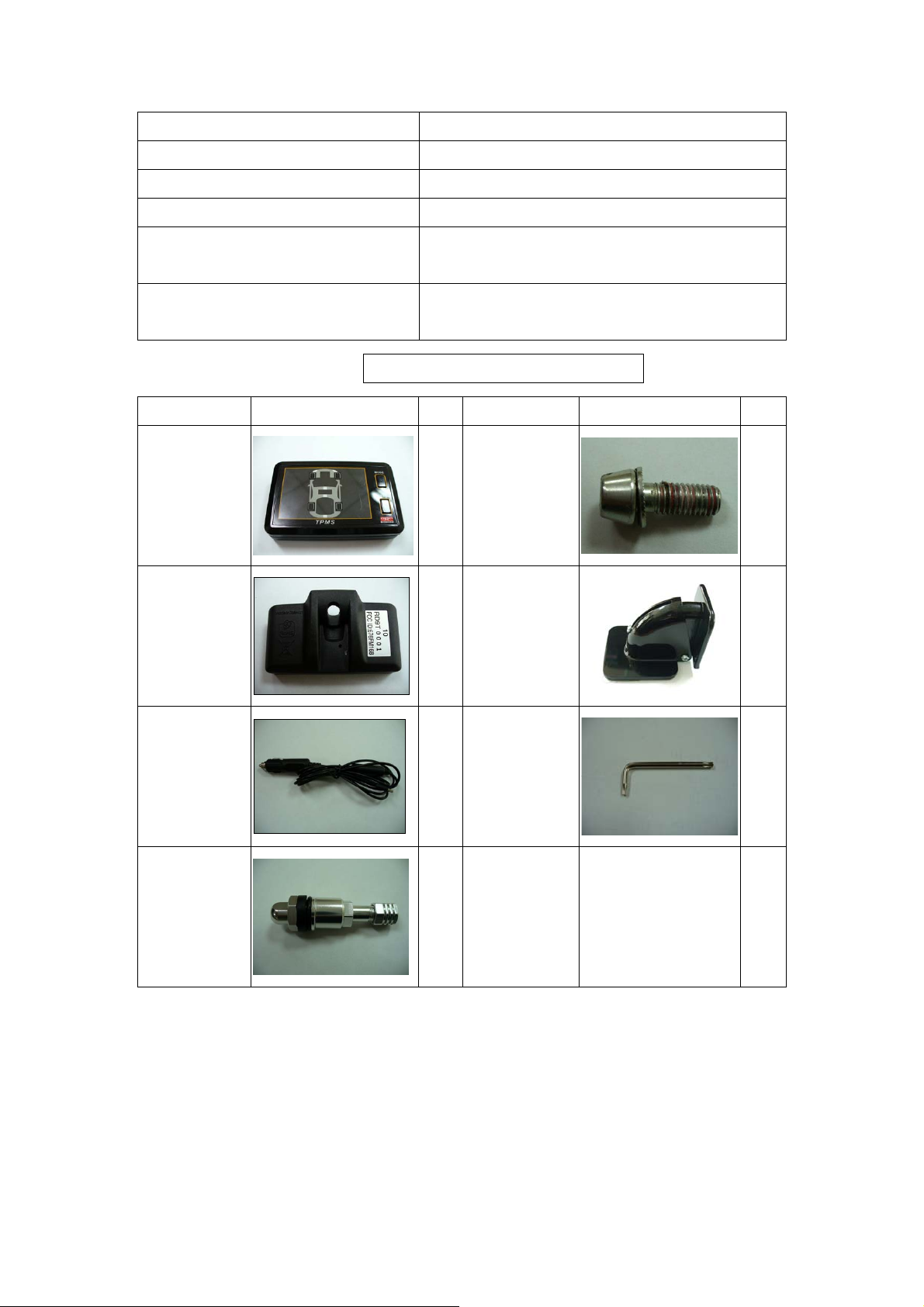
W401A TPMS Accessories
Accessories Pictures QTY Accessories Picture QTY
Display
Tire Sensor 4 Magnetic Holder
1 Nylok Screw
5
1
Cigarette Power
Cable
Aluminum Valve 4
T-20
1
Screw Driver
Manual
1
Page 5
W401A TPMS INSTALLATION
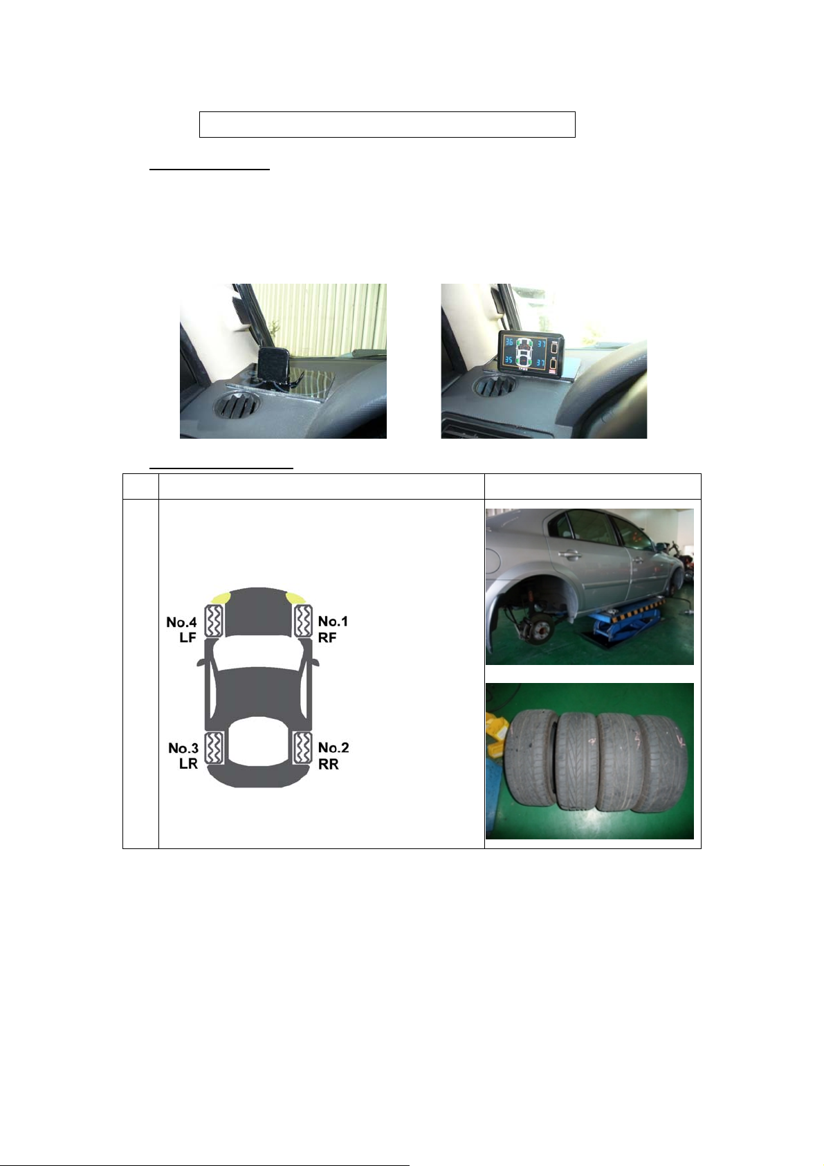
1. Display Installation:
a. Firm the magnetic holder in the suitable place. (Suggest place , as shows in the picture)
b. Plug in the USB cigarette power cable on the back of display.
c. Put the display on the magnetic holder.
d. Plug in the power cable to the cigarette lighter power connection.
2. Tire Sensor Installation:
Step Operation Process Photograph
a Take off the 4 tires and mark 1~4 for each tire position.
No.4 = Left Front Tire ; No.1 = Right Front Tire。
No.3 = Left Rear Tire ; No.2 = Right Rear Tire。
Page 6
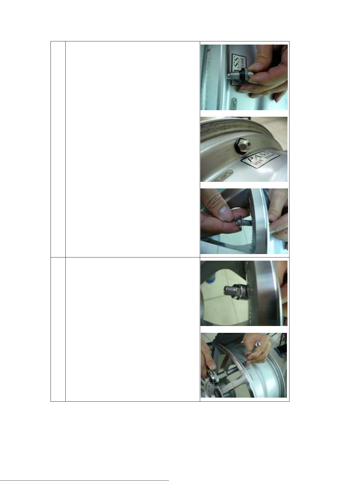
b Take off the tire and bleed the air, then should change to
the ORO-TEK TPMS valve, and follow the steps:
1. Snap in the valve from the internal edge side of the
wheel.
2. Adjust the valve’s angle, and make the valve be
vertical by the edge of the wheel.
3. Put on the circle screw from the outside of the wheel.
4. Tight up the valve with the nylok screw from the
outside of the wheel.
5. Use the 6 angle screwdriver to tight up.
b
Page 7
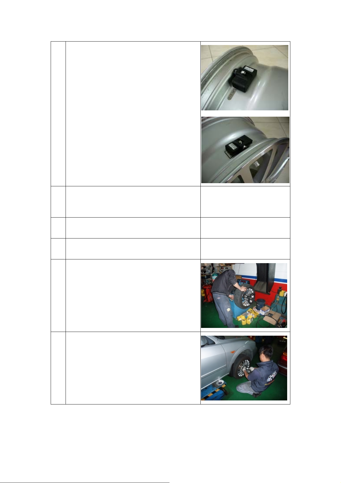
c Put the marked No. 1 tire sensor to the tire which market
No. 1. as step a. photo and follow steps:
1. Install the tire sensor to the valve.
2. Use the nylok screw and tight up with the tire sensor.
(Pls. use the screwdriver which is included to the
accessories bag)
3. Adjust the tire sensor’s angle (paste on the surface of
the wheel), then tight up the with the nylok screw.
4. Put on the valve’s cap, and finish the installation.
When there is necessary to re-install the tire sensor, pls.
use the new nylok screw in order to prevent to re-use the
old ones.
d Put on the No. 2 tire sensor to the tire which marked
No.2, and set up the other 2 sensor in the same manner as
shows in the step c.
e Make sure there is no other liquid or dust beside of the
tire sensor.
f Follow the tire specification and inflate appropriate air to
the tire after finished the installation.
Balance the tires with the balance machine。
g
h Put back the tires to it’s corresponding position as shows
in the photograph on step a.
Turn on the ignition after the TPMS installation and start to monitoring the tire pressure/temperature
and car battery.
Page 8
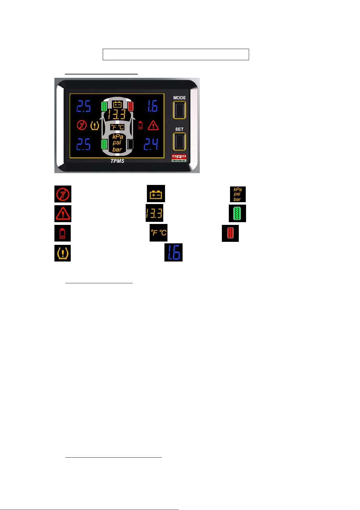
W401A Systems Operation
1. Display Signals Description:
:Bad Transmission Signal。 :Battery Signal。 :Pressure Unit 。
:Tire deflating signal。 :Battery Voltage unit。 :Normal Tire Pressure。
:Low Battery on Tire Sensor。 :Temperature Unit。 :Abnormal Tire Pressure。
:Abnormal Tire Condition Signal。 :Tire Pressure/Temperature display unit。
2. Display System Operation
ORO-W401A got 3 different mode for user, whi ch are Tire Pressure Display Mode, Temperature
Display Mode, Pressure-Temperature rotation mode, the display will show the pressure mode after turn
on, for enter the temperature monde can press once and pressure-temperature by another once. The
system will monitoring the tire pressure, tire temperature, battery voltage no matter what kind of
information are showing in the display and be alarmed whenever abnormal happens. If the user does
not modifying from the factory default, the system will return back to the tire pressure display, the 3
modes of display are as follow’s:
a. Pressure Display Mode: Displaying the 4 tires pressure and battery voltage unit only.
b. Temperature Display Mode: Displaying 4 tires temperature and battery voltage unit only.
c. Pressu re-Temperature Rotation Display mode: Change the pressure and temperature unit by
rotating, and display battery voltage immovable.
ORO-W401A includes bar, kPa, psi which are 3 kinds of pressure’s unit and ℃、℉ for temperature
unit for user, the factory default for pressure unit is bar, the user can change the pressure unit by
pressing the MODE button for 2 sec., and the factory default for temperature is ℃, the user can
change the temperature unit by press MODE button for 2 sec.
3. Modify the factory default operation:
Page 9
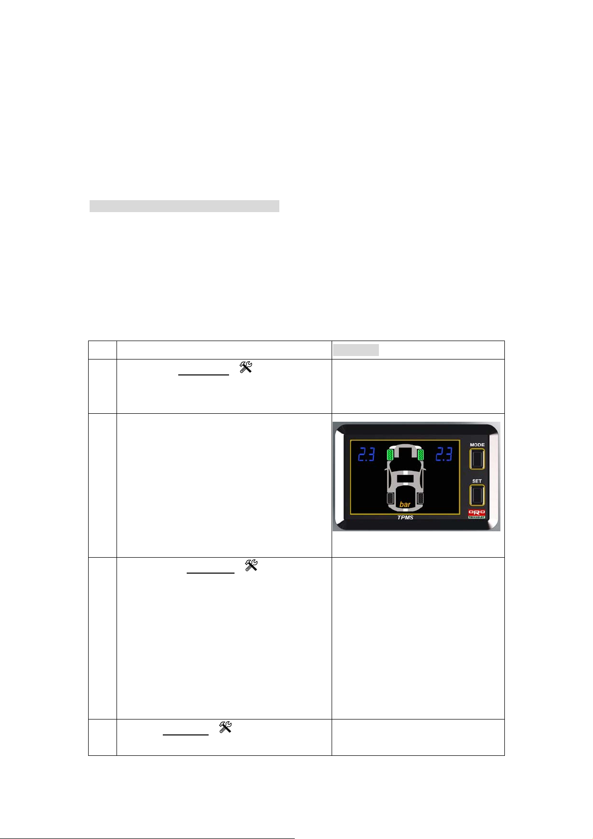
ORO TEK W-401A exists 4 modes of factory default for user to choose, the parameter should be
modified by formal procedure. Press the SET UP button continuously for 2 sec. to be entered the set up
mode from Front tire-Std. tire pressure set up, Rear Tire-Std. tire pressure set up, Tire
Temperature-Over Temperature Warning, Operating Mode and others parameters setting, and pls. refer
below process:
NOTE: The user should change the suitable pressure unit for own vehicle before entered into the
setting mode.
FRONT TIRE-Low Tire Pressure Setting Mode
When the tire is under non-deflate condition, the pressure will increase and decrease simultaneously
with the temperature, normally, there will be 1psi (7kPa) when the temperature got difference of 10℉
(6℃), and this is normal physics phenomenon. ORO TEK suggest to the user , when is checking on tire
pressure, it’s important to keep the tire pressure under suitable pressure, the Low tire pressure unit will be
recognized as warning unit, however, when the pressure is higher than 25% from the cold tire unit, the
system will start the alarming.
Warning: Low Tire-Std. Tire Pressure setting unit, pls. check on each vehicle’s user manual.
Step Operating Process
a
Pressing the setup key
for over 2
seconds can enter to the low pressure set up
mode.
The wireless receiver and display unit will now
b
show the low tire pressure factory default value
(2.3bar) shown in blue light and the yellow light
indicates the ”bar”. or pre-selected units ( kPa or
psi), if do not to modify anything, then press the
Set Up buton for enter next setting mode.
NOTE: If the pressure unit is kPa the display will
show 230 and 32 for Psi by flasing
c
By pressing the Mode key
once, the low
tire pressure value will add 1 unit; and the unit
value will add 0.1 bar by each press, when it has
reached 2.8 bar the system unit will return to 19
bar.
Photograph
NOTE: If the user is settee by kPa, will add 10
kPa by each pressing, the range for kPa is
190kPa~280kPa, and 27 psi ~ 40 psi for PSI
unit.
d
Press the setup key
to exit the low tire
pressure warning value setup mode. The
Page 10
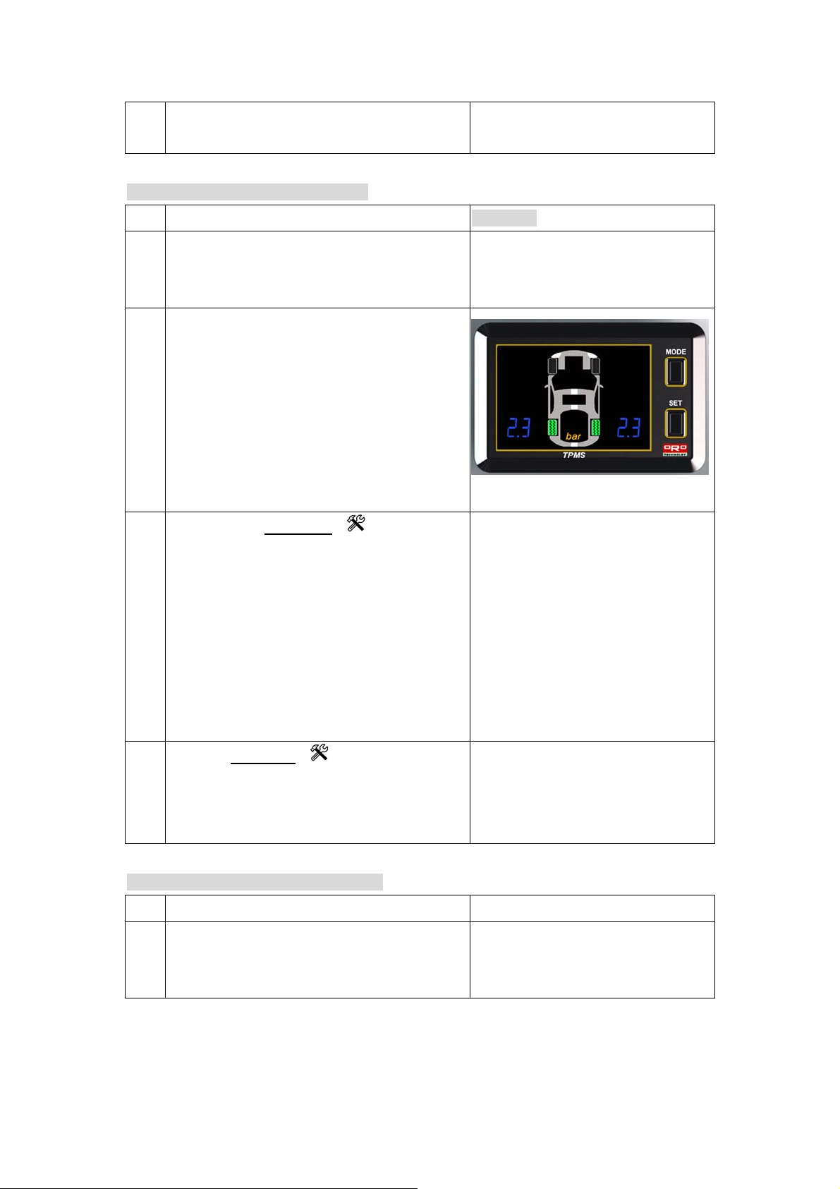
system will automatically enter the Rear tire Low
pressure set up mode.
Rear Tire-Low Tire Pressure Setting Mode
Setp Operating Process
The system will enter the Rear Tire low pressure
a
set up mode automatically after set up the Front
Tire Low Pressure set up mode.
The wireless receiver and display unit will now
b
show the low tire pressure factory default value
(2.3bar) shown in blue light and the yellow light
indicates the ”bar”. or pre-selected units ( kPa or
psi), if do not to modify anything, then press the
Set Up buton for enter next setting mode.
NOTE: If the pressure unit is kPa the display will
show 230 and 32 for Psi by flasing
c
By pressing the Mode key
once, the low
tire pressure value will add 1 unit; and the unit
value will add 0.1 bar by each press, when it has
reached 2.8 bar the system unit will return to 19
bar.
Photograph
NOTE: If the user is settee by kPa, will add 10
kPa by each pressing, the range for kPa is
190kPa~280kPa, and 27 psi ~ 40 psi for PSI
unit.
d
Press the setup key
to exit the low tire
pressure warning value setup mode. The
system will automatically enter the tire
temperature set up mode.
Tire Temperature-Over Temperature W arning
Step Operating Process Photograhp
The system will enter the Over Tire Temperature
a
set up mode automatically after set up the Rear
Tire Low Pressure set up mode.
Page 11
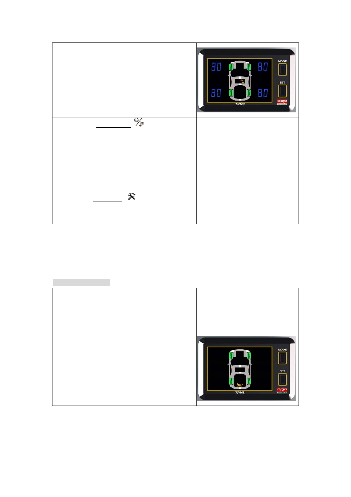
The display shows on the figure is the tires
b
factory default high temperature value (80
the tires in blue. If there is no modification to the
user, then press the Set Up button to enter the
next set up mode.
NOTE: If the unit is ℉ the number will be
flashing in 176.
o
C) for
c
Press the function key
to change the high
temperature figure, the unit will add 1 ℃ by each
pressing, the range for temperature set up are
between 60℃~99℃, the system will return back to
60℃ after 99℃.
NOTE: If the unit is ℉, will add 1℉ on each
pressing, the range for ℉ is from 140℉~212℉
d
Push the setup key
to complete the Over
Tire temperature setting operation and th e
display will enter to the turn on mode.
Power On Setting Mode
Step Operating Process Photograph
The system will enter the Power On set up mode
a
automatically after Over Tire Temperature set
up mode.
The display shows on the figure is factory
b
default for tire pressure value is bar in yellow.
NOTE: The system may use other unit for
pressure by psi, kPa or bar, depending the
system for different area of the world.
Page 12
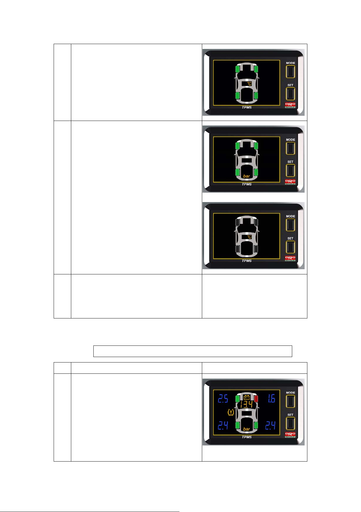
Press the Mode button, will enter to the
y
c
temperature display mode as the picture on the
right hand side, and the unit for temperature is
℃.
NOTE: The system may use other unit for
pressure by ℃、℉ , depending the system for
different area of the world.
d
Press the Mode button, will enter to the Tire
Pressure~ temperature by rotation mode. And
the battery voltage will display permanently.
e
Press the Set Up button, the system will
complete the Power On mode the back to the
normal operation mode to monitoring tire
pressure/temperature and battery voltage.
W401A System Alarm Mode Description
Mode Warning Condition and Warning Method Display Figure
1
Warning Situation: When the tire pressure > Low
tire std. pressure * 1.25 or tire pressure < Low
pressure std. pressure * 0.75 , the s
warning.
(Factory Default for low tire pressure is 2.3bar, so
the systems will start warning when the tire
pressure > 2.9bar or below 1.7bar.
Warning Method: Will sound Beep Beep as
stem will start
Page 13
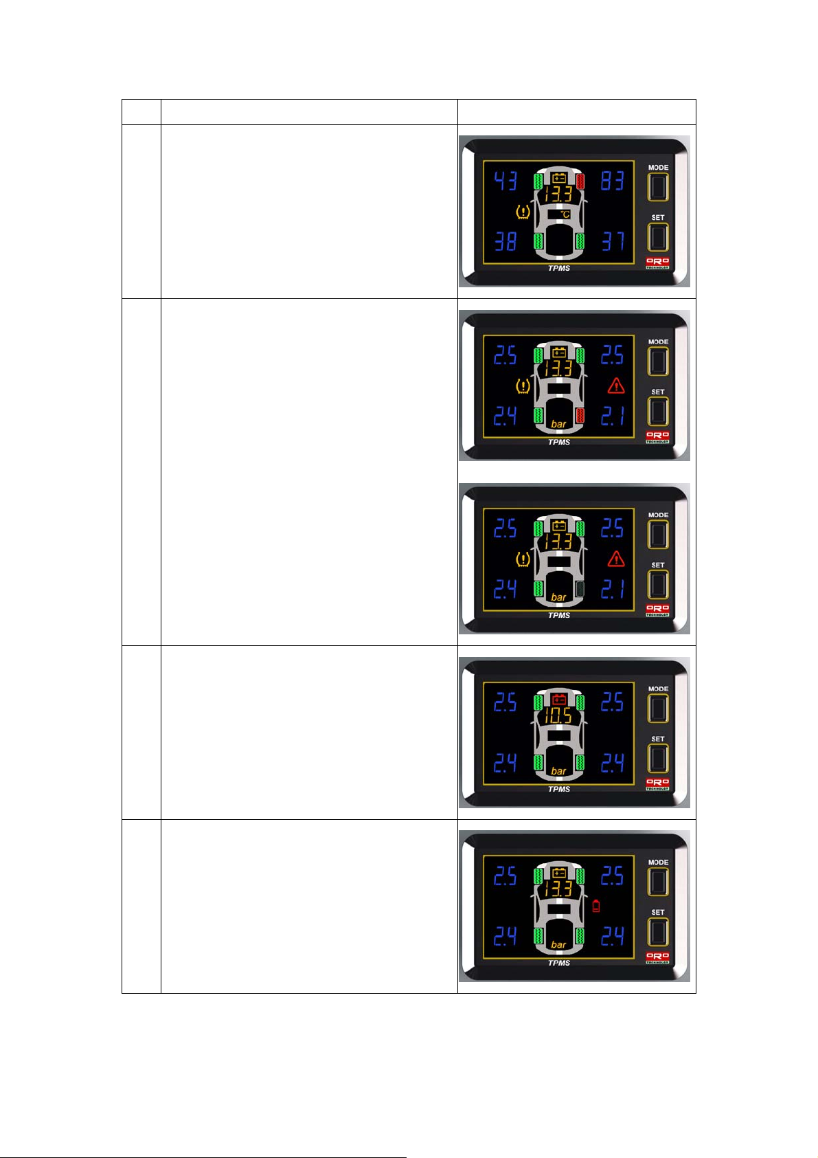
warning when the tire figure displayed in RED.
2
Warning Situation: When the temperature is
higher than set up unit. (F actory default is 80℃
and 176℉
Warning Method: Will sound Beep Beep as
warning when the tire figure displayed in RED.
3 Warning Situation: When the tire pressure is
deflating rapidly.
Warning Method: When the tire figure flashing in
RED with deflating rapidly signal by Bee p Beep
warning sound.
4 Warning Situation: When the battery voltage is
below than set up unit.
(Factory default for warning is 11.5V)
Warning Method: The battery figure will show in
RED.
5 Warning Situation: When the tire sensor is low
battery.
(Suggest to change the sensor as earlier as possible)
Warning Method: The tire will flash in green, and
the low battery figure will lighting.
Page 14
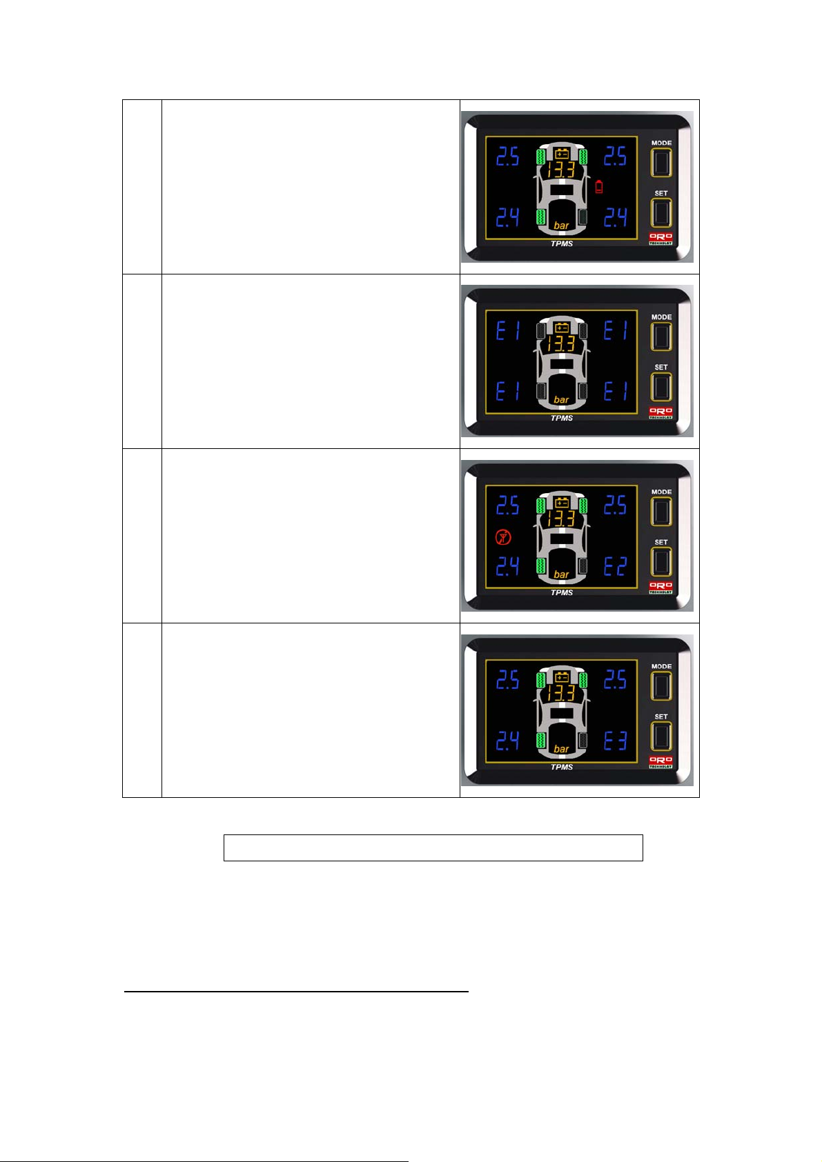
6 Warning Situation: When the Monitor run ou t of
initial setting up by factory default.
Warning Method: The four display unit will show by
E1 and not lighting on four tires figures.
7 Warning Situation: When Monitor sensor can not
receive one of the tire sensor, over than 9 min..
Warning Method: The failure tire sensor will show
by E2 without light on tire figure.
8 Warning Situation: When the tire sensor got failure
on factory default.
Warning Method: The monitor will show by E3 on
the failure tire sensor without tire light figure.
NOTE: The user can press the MODE button continuously for 3 sec. to stop the warning sound.
W401 Reset for Tire Changing and Rotation
When the user are doing/finished the changing or rotating the tires, should also reset
the monitors ID’s position, however, ORO TEK TPMS provides 4 modes in order to
make the user can reset rapidly and keep the tire position as same as shows by the monitor.
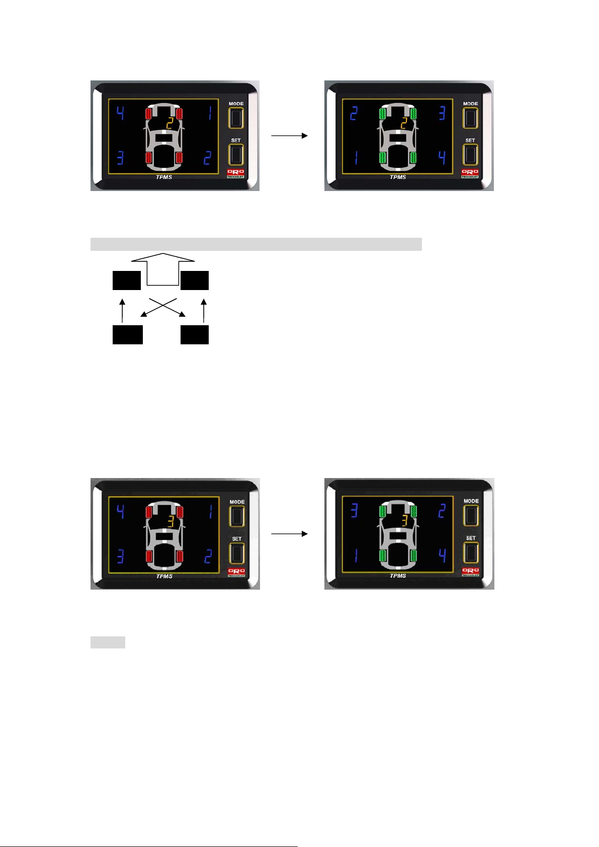
Set Up Process for Enter the Tire Changing and Rotation
Press the Set Up and Mode button simultaneously for 3 sec., the system will enter set up mode 1, mode
2, mode 3, mode 4 and turn back to the normal monitoring display by pressing once a time.
Page 15
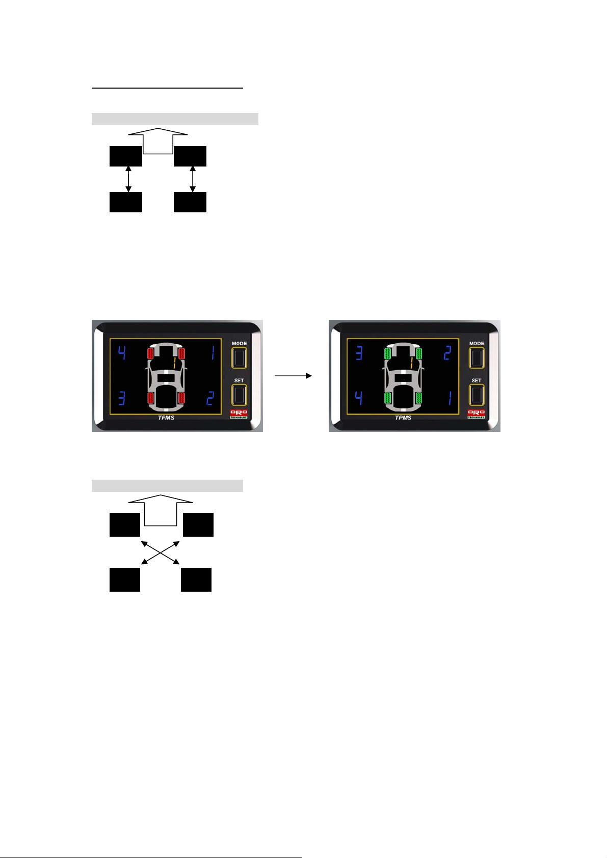
Description for each set up process
Mode 1: Front and Rear ti re exchange
FRONT
The monitor will show up as below photograph, the NO. 1 which shows in yellow means the mode 1,
and the 4 red lights means the tire position before reset as shows in pic. 1, the 4 green lights means the
mode 1 has been completed set up.
Press the Set Up button continuously for 2 sec. until sounds Beep which means has accomplished the
set up for mode 1. (Front and Rear Tires Exchange)
Pic. 1 Pic. 2
Mode 2: Tir e Di a go nal E xchanged.
No4
FRONT
No 1
No 3
No 2
The monitor will show up as below photograph (Pic. 1 and Pic 2), the No. 2 in yellow means in mode 2.
and the 4 red lights means the tire position before reset as shows in pic. 1, the 4 green lights means the
mode 2 has been completed set up.
Press the Set Up button continuously for 2 sec. until sounds Beep which means has accomplished the
set up for mode 2. (Tire Diagonal Exchange), then the system will back to the normal operating
display.
Page 16
Pic. 1 Pic. 2
模式 3:Front Tire Diagonal exchange, Rear Tire parallel change to the front
FRONT
The monitor will show up as below photograph (Pic. 1 and Pic 2), the No. 3 in yellow means in mode 3.
and the 4 red lights means the tire position before reset as shows in pic. 1, the 4 green lights means the
mode 3 has been completed set up.
Press the Set Up button continuously for 2 sec. until sounds Beep which means has accomplished the
set up for mode 3. ( Front Tire Diagonal Exchange, Rear Tire Parallel exchange to front), then the
system will back to the normal operating display without any changing.
Pic 1 Pic 2
Mode 4 Random re-position tires
The user should install the tire to their random position before enter mode 4.
The monitor will display No. 4 in yellow which means Mode 4.
The user should reset from Right Front Tire -> Right Rear Tire -> Left Rear Tire -> Left Front Tire in
order to complete the set up mode 3.
Page 17
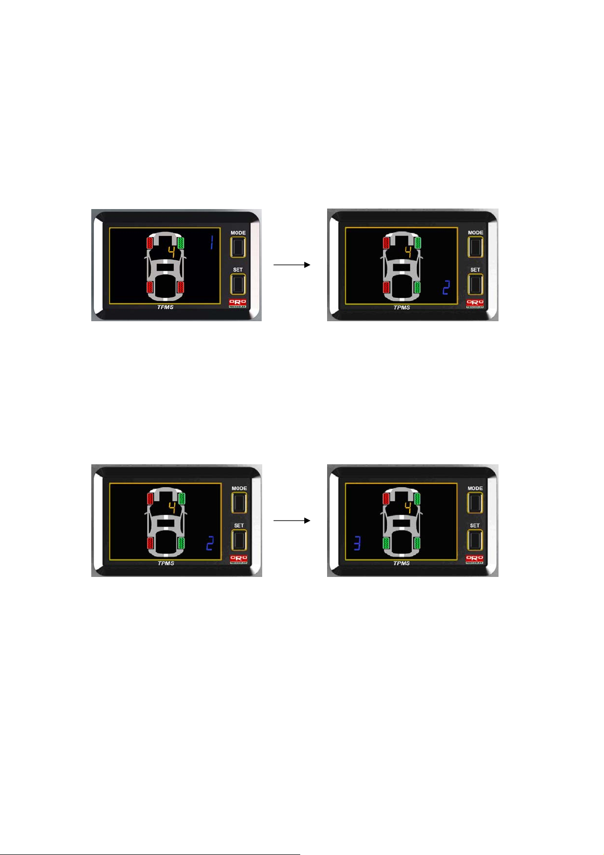
1. Set up for RF tir e sens or :
The display will flash green and red with No. 1 which means the RF tire can be proceed for the
set up as below pic. 1, by the meantime the user should deflate the tire pressure rapidly over
than 0.3bar/30kPa or 4 Psi in 15 sec. until sounds Beep, which means the user is completed
the set up for RF tire as shows on below pic. 2. If there is no need to set up the RF tire sensor,
just press the Set Up mode button to jump over this process.
Pic 1 Pic 2
2. Set up for RR tire Sensor.
The display will flash green and red in tire figure and No. 2 which means the RR tire can be
proceed for the set up as below pic. 1, by the meantime the user should deflate the tire
pressure rapidly over than 0.3bar/30kPa or 4 Psi in 15 sec. until sounds Beep, which means
the user is completed the set up for RR tire as shows on below pic. 2. then the systems will
enter to the LR tire sensor set up mode.
Pic 1 Pic 2
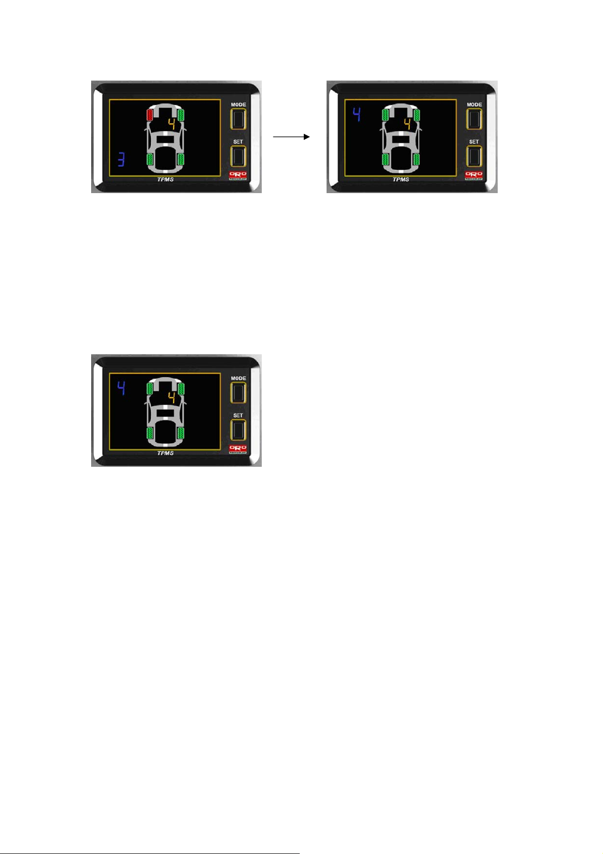
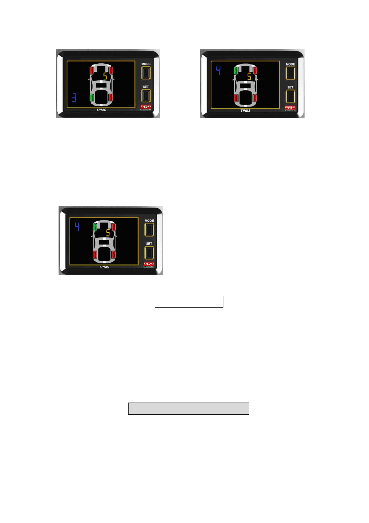
3. Set up for LR tire sensor.
The display will flash green and red in tire figure and No. 3 which means the LR tire can be
proceed for the set up as below pic. 1, by the meantime the user should deflate the tire
pressure rapidly over than 0.3bar/30kPa or 4 Psi in 15 sec. until sounds Beep, which means
the user is completed the set up for LR tire as shows on below pic. 2. then the systems will
enter to the LF tire sensor set up mode.
Page 18
Pic 1 Pic 2
4. Set up for LF tire sensor
The display will flash green and red in tire figure and No. 4 which means the LF tire can be
proceed for the set up as below pic. 1, by the meantime the user should deflate the tire
pressure rapidly over than 0.3bar/30kPa or 4 Psi in 15 sec. until sounds Beep, which means
the user is completed the set up for LF tire as shows on below pic. . then the systems will enter
back to the normal operating display.
Pic 1
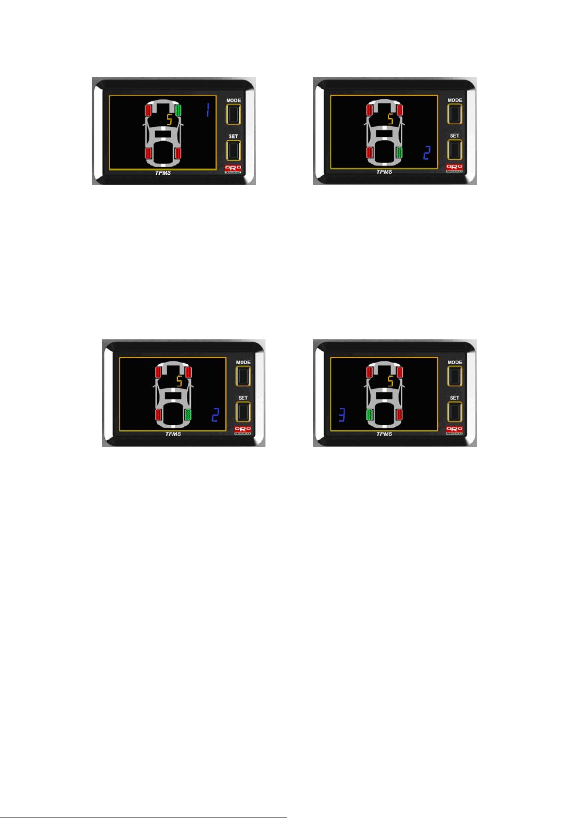
Mode 5 Single sensor replaced
The monitor will display No. 3 in yellow which means Mode 5.
The user should reset from Right Front Tire -> Right Rear Tire -> Left Rear Tire -> Left Front Tire in
order to complete the set up mode 5 and back to the normal operating mode.
1. Set up for Right Front Tire sensor:
The display will flash green and red with No. 1 which means the RF tire can be proceed for the
set up as below pic. 1, by the meantime the user should deflate the tire pressure rapidly over
than 0.3bar/30kPa or 4 Psi in 15 sec. until sounds Beep, which means the user is completed
the set up for RF tire as shows on below pic. 2. If there is no need to set up the RF tire sensor,
just press the Set Up mode button to jump over this process.
Page 19
Pic 1 Pic 2
2. Set up for RR tire sensor
The display will flash green and red in tire figure and No. 2 which means the RR tire can be
proceed for the set up as below pic. 1, by the meantime the user should deflate the tire
pressure rapidly over than 0.3bar/30kPa or 4 Psi in 15 sec. until sounds Beep, which means
the user is completed the set up for RR tire as shows on below pic. 2. then the systems will
enter to the LR tire sensor set up mode.
Pic 1 Pic 2
3. Set up for LR tire sensor.
The display will flash green and red in tire figure and No. 3 which means the LR tire can be
proceed for the set up as below pic. 1, by the meantime the user should deflate the tire
pressure rapidly over than 0.3bar/30kPa or 4 Psi in 15 sec. until sounds Beep, which means
the user is completed the set up for LR tire as shows on below pic. 2. then the systems will
enter to the LF tire sensor set up mode.
Page 20
Pic 1 Pic 2
4. Set up for LF tire sensor
The display will flash green and red in tire figure and No. 4 which means the LF tire can be
proceed for the set up as below pic. 1, by the meantime the user should deflate the tire
pressure rapidly over than 0.3bar/30kPa or 4 Psi in 15 sec. until sounds Beep, which means
the user is completed the set up for LF tire as shows on below pic. . then the systems will enter
back to the normal operating display, without any changing.
Pic 1
Warning
The user should be secure that the monitor should be plug in to the power, when is processing the tire
changing/rotating mode, if the power is interrupt, just follow the reset process in order to proceed
successfully . The user should confirm whether the display can monitor all the tire information correctly,
if not, just follow the reset process.
The user should confirm whether the all sensors are manufactured by ORO TEK before do any
changing or replacement,, if not, the user won’t be able be succeed on set up neither make the system
operating normally.
ORO-TEK Warranty Policy
We warrant our products for one year (365 days) from the date of original purchase to be free
from defects in materials and workmanship. If, during this period, the product fails under
normal usage, because of a manufacturing defect, we will replace or repair the item. To obtain
repair or replacement under the terms of this warranty, please return the product to the place
of purchase. Proof of purchase and date of purchase are required to validate the warranty
claim. If cannot proof the warranty will be just 2 months. For ex: (2009/1, the warranty period is
until 2009/3)
Page 21

All implied warranties, including the warranty of merchantability, are limited to this same
ninety-day period from date of original purchase. We are not liable for any direct or
consequential loss or property damage arising from any use of this product. This warranty
gives you specific legal rights, and you may also have other rights, which vary from state to
state. This does not affect your statutory rights.
The follow’s situations are out of warranty policy even the product are remain in the warranty duration
1. Broken or damaged on appearance of the product.
2. The barcode label is not clear or broken/destroy the barcode label.
3. The user did not follow the user manual instruction on installation, incorrect installation, or bad
keeping to make the systems become failure or damaged.
4. The system has been installed by non-authorized distributor or technician from ORO-TEK.
5. When the user is not using the original manuf acturer’s accessories (ex: Power code) and make the
system become failure, this are NOT included ORO-TEK warranty policy.
6. Any natural catastrophe/bad installation or any re-model process without authorization by the
manufacturer or any un-natural installation are NOT included ORO-TEK warranty policy.
7. Consumption parts which should be repl aced on time.
Annexes
Annex 1
kPa , psi, bar Conversion Table
kPa psi bar kPa psi bar kPa psi bar
10 1 0.1 210 31 2.1 410 60 4.1
20 3 0.2 220 32 2.2 420 61 4.2
30 4 0.3 230 34 2.3 430 63 4.3
40 6 0.4 240 35 2.4 440 64 4.4
Page 22

50 7 0.5 250 37 2.5 450 66 4.5
60 9 0.6 260 38 2.6 460 67 4.6
70 10 0.7 270 39 2.7 470 69 4.7
80 12 0.8 280 41 2.8 480 70 4.8
90 13 0.9 290 42 2.9 490 72 4.9
100 15 1.0 300 44 3.0 500 73 5.0
110 16 1.1 310 45 3.1
120 18 1.2 320 47 3.2
130 19 1.3 330 48 3.3
140 20 1.4 340 50 3.4
150 22 1.5 350 51 3.5
160 23 1.6 360 53 3.6
170 25 1.7 370 54 3.7
180 26 1.8 380 55 3.8
190 28 1.9 390 57 3.9
200 29 2.0 400 58 4.0
Annex II
℃ To ℉ and ℉ To ℃ Conversion Table
℃ ℉
-40 -40 20 68 80 176
-30 -22 30 86 90 194
-20 -4 40 104 100 212
-10 14 50 122 110 230
0 32 60 140 120 248
10 50 70 158 125 257
℃ ℉ ℃ ℉
 Loading...