

Page 1
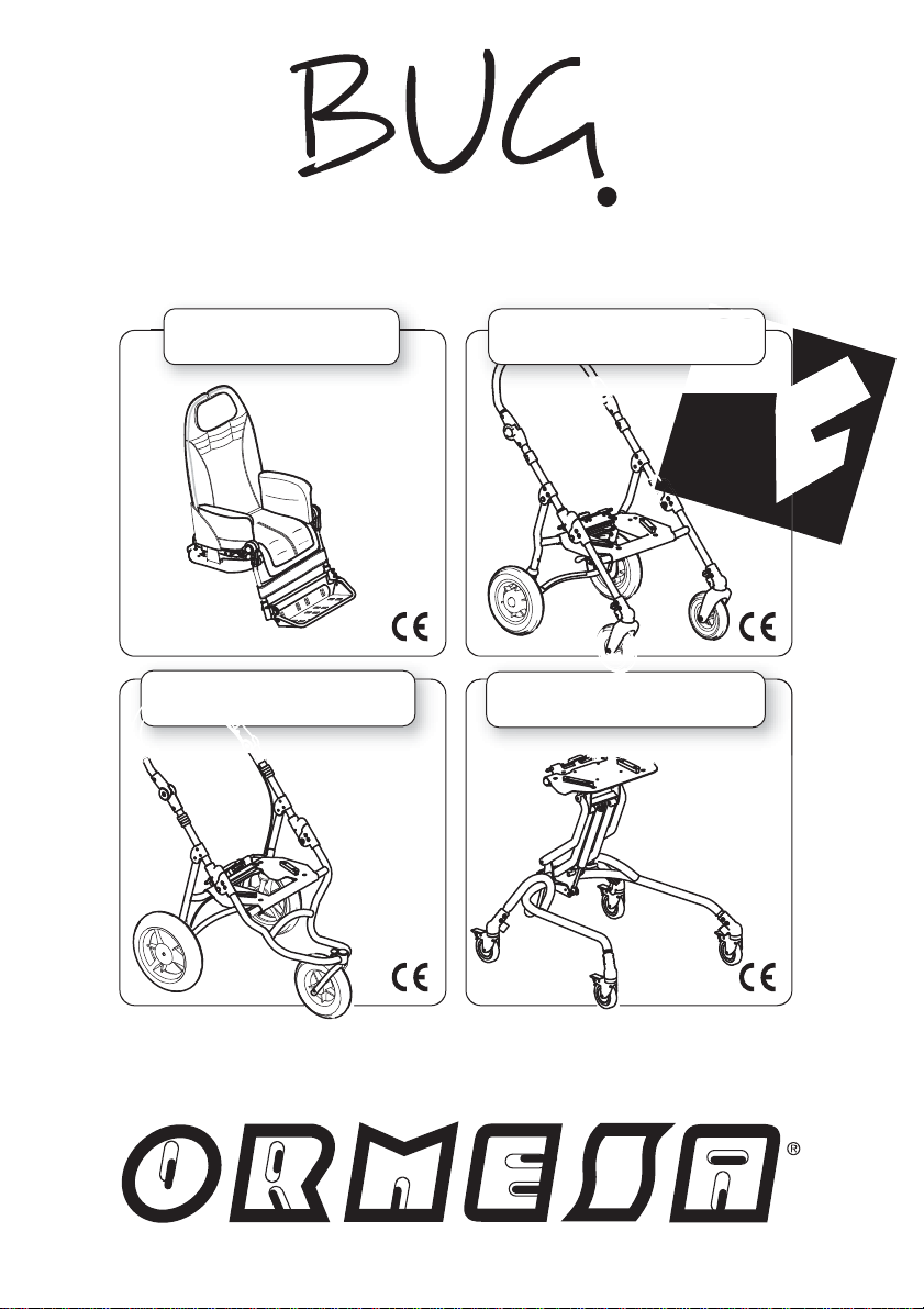
modular seating system
6
INGLESE - Cod. 22179 28-02-13
SEAT UNIT
WITH 4-WHEEL BASE
WITH INDOOR BASEWITH 3-WHEEL BASE
869
ISO 7176/19 - ANSI RESNA WC/19
856901
USE AND MAINTENANCE HANDBOOK
Page 2

Page 3

Thank you for choosing Bug, from ORMESA s.r.l.
The Bug combines style and ergonomics without compromising on safety.
Bug is a complete seating system with recline and tilt space, that grows w ith your child. It
can be placed on any flat surface and it is available with three different base units (4 wheel base
and 3 wheel base for outdoor use; feeding base for indoor use).
ORMESA s.r.l. recommends that you read this manual very carefully to understand its
contents fully. In addition to help you become familiar with the seat quickly, it also contains
practical tips for making the best use of it safely and keeping it in good working order.
If, after reading it, you still have questions, contact your retailer, who will be happy to help you, or
call ORMESA directly at +39 0742 22927, send a fax to +39 0742 22637 or send an e-mail to:
[email protected]
Luigi Menichini
Managing Director
1/9
Page 4
TABLE OF CONTENTS
WARNINGS ........................................................................................................................................ 4
GUARANTEE ..................................................................................................................................... 9
HOW TO STORE AND TRANSPORT THE MEDICAL DEVICE ....................................................... 9
SOME EXAMPLES OF WHAT NOT TO DO WITH THE PRODUCT ................................................ 10
HOW TO TILT THE BUG AND CLIMB UP PAVEMENTS ................................................................ 11
BUG WITH 4-WHEEL BASE 869 ................................................................................................... 11
BUG WITH 3-WHEEL BASE 901 ................................................................................................... 12
HOW TO USE THE BUG 4-WHEEL STROLLER WITH 869 BASE FOR TRANSPORT ON A
MOVING VEHICLE (private cars, buses, etc.) ................................................................................ 13
LABELS AND PLATES ..................................................................................................................... 18
WHAT Bug IS..................................................................................................................................... 19
TECHNICAL FEATURES .................................................................................................................. 19
base 869 and 901 BRAKING ........................................................................................................ 20
base 856 BRAKING ....................................................................................................................... 20
INITIAL PREPARATION .................................................................................................................... 21
PACKAGING INFORMATION ........................................................................................................ 21
HOW and WHERE TO HOLD the COMPONENTS of BUG .......................................................... 21
BUG SEAT UNIT ................................................................................................................................ 22
SEATING UNIT ADJUSTMENTS ON BASES 869, 901 AND 856 .................................................... 23
ADJUSTING THE INCLINATION OF THE SEAT (TILT-IN-SPACE SYSTEM) ............................. 23
RECLINING THE BACKREST ....................................................................................................... 24
ADJUSTING THE HEIGHT OF THE BACKREST ......................................................................... 25
ADJUSTING THE WIDTH OF THE SEAT BASE ........................................................................... 26
ADJUSTING THE LEGREST ......................................................................................................... 27
ADJUSTING THE FOOTREST ...................................................................................................... 28
ADJUSTING THE DEPTH OF THE SEAT ..................................................................................... 29
Bug seat with 4-WHEEL base 869 .................................................................................................. 30
TECHNICAL SPECIFICATIONS of Bug with four wheel BASE 869 .............................................. 31
HOW TO USE Bug WITH BASE 869 ................................................................................................ 33
OPENING the STROLLER ........................................................................................................... 33
HOW TO ATTACH THE SEAT TO THE FRAME ........................................................................... 34
HOW TO REVERSE THE SEAT SO THAT THE CHILD FACES HIS MOTHER (FIG. A) ............. 35
HOW TO DETACH THE SEAT FROM THE FRAME ..................................................................... 36
FO L D I N G THE BASE .................................................................................................................. 37
ADJUSTING THE INCLINATION OF THE HANDLE ..................................................................... 38
FRONT WHEEL DIRECTION LOCKS ........................................................................................... 38
Bug seat with 3-WHEEL base 901 .................................................................................................. 39
TECHNICAL SPECIFICATIONS of Bug with 3 wheels BASE 901 ................................................. 40
HOW TO USE Bug WITH BASE 901 ............................................................................................... 42
2/92
Page 5

OPENING THE BASE .................................................................................................................... 42
HOW TO ATTACH THE SEAT TO THE FRAME .......................................................................... 43
HOW TO DETACH THE SEAT FROM THE FRAME .................................................................... 44
FO L D I N G THE BASE .................................................................................................................. 45
ADJUSTING THE INCLINATION OF THE HANDLE ..................................................................... 46
FRONT WHEEL DIRECTION LOCKS ........................................................................................... 46
Bug with BASE 856_ ....................................................................................................................... 47
TECHNICAL SPECIFICATIONS of Bug with BASE 856 ................................................................ 48
HOW TO USE Bug WITH BASE 856 ............................................................................................... 50
HOW TO ATTACH THE SEAT TO THE FRAME .......................................................................... 50
HOW TO DETACH THE SEAT FROM THE FRAME .................................................................... 51
ADJUSTING THE HEIGHT OF THE SEAT ................................................................................... 52
MOUNTING THE ACCESSORIES .................................................................................................... 54
HEADREST with OCCIPITAL-PARIETAL PROTECTIONS 863 ................................................. 54
HEADREST with PARIETAL PROTECTIONS 852 ..................................................................... 56
LEG DIVIDING INGUINAL STRAPS 817 .................................................................................... 58
THERMIC COVER 818 ............................................................................................................... 58
CANOPY 819 .............................................................................................................................. 59
RAIN COVER 825 ....................................................................................................................... 60
FOOT STRAPS 827 .................................................................................................................... 61
Padded ABDUCTION BLOCK 834 .............................................................................................. 61
FRONT HANDLE 839 ................................................................................................................. 62
FLEXIBLE AND WRAP-AROUND SIDE SUPPORTS FOR THE TRUNK 868 ........................... 63
891 TIEDOWN HOOKS (4 RINGS) 891...................................................................................... 64
VEST HARNESS 853 .................................................................................................................. 64
NET BASKET 858 ....................................................................................................................... 65
45° SEAT BELT 894.................................................................................................................... 65
Padded SIDE SUPPORTS 838 ................................................................................................... 66
TRAY 824 .................................................................................................................................... 67
5-POINT VEST HARNESS 903 .................................................................................................. 68
5-POINT HARNESS
PARASOL 854 ............................................................................................................................ 71
PADDED COVERING for FOOTPLATE 892 .............................................................................. 74
HAND BRAKE 905 ...................................................................................................................... 75
VENT TRAY 911 ......................................................................................................................... 80
4-POINT SEAT BELT 920 ........................................................................................................... 82
SIBLING REAR FOOTBOARD 921 ............................................................................................ 84
BOTTLE HOLDER 922 ............................................................................................................... 87
ATTACHING THE CUSHION ............................................................................................................ 88
MAINTENANCE, CLEANING AND DISINFECTION ......................................................................... 90
CUSTOMER SERVICE AND SPARE PARTS ................................................................................... 91
CONDITIONS FOR DURABILITY, REUSE AND REASSIGNMENT TO A NEW USER ................. 92
906 ............................................................................................................. 69
3/92
Page 6
WARNINGS
- CAREFULLY READ AND UNDERSTAND THE INSTRUCTIONS IN THIS MANUAL
BEFORE USING THE DEVICE BECAUSE THEY HAVE BEEN WRITTEN WITH
THE USER'S SAFETY IN MIND and they will help the carer use the product safe ly
and keep it in good working order. The Us e and Maintenance Manual is an integral
part of the product and must be carefully preserved for future reference.
- The manual is intended for technically qualified retailers and users and their
assistants; it provides instructions for its correct use and must be supplemented by
adequate knowledge of the rehabilitation program for which it has been prescribed.
- The manual reflects the technical state of the product at the time it was sold.
ORMESA s.r.l. reserves the right to make any changes to the product or manual
suggested by experience, technical considerations or regulatory developments
without any obligation to update its previous production and relevant manual.
- The use of the device and its accessories must be checked by a specialized
doctor, in conformity with the laws and standards in force.
- The Bug is intended for use by people whose size and weight fall within the
range of the "Technical Specifications" on pages 31-32, 40-41, 48-49 and was
exclusively designed for the transport and placement of ch ildren.
- Bug is available in two sizes: change to a larger device as the child grows
- Bases 869 and 901 were designed for outdoo r use. Base 856 is only intended
for indoor use.
- The 812 direction locks on the front w heels of outdoor bases were exclusively
designed to use the aid on rough terrain: in all other cases, they must be
disengaged to avoid difficulty in manoeuvring the device
- The aid Bug with 869 and 901 bases, mu st be manoeuvred by people with the
height and strength to control its movements
- Before each use always check that brakes are working, the wheels are not
excessively worn and that the frame, backrest and footrest are locked
- Make sure that all adjustable parts are locked before each use
- When parking, always apply both brakes, even on level ground
4/92
Page 7
- Always lock the brakes before making any type of adjustment
- The PADDED UPHOLSTERY IS FIRE-RETARDANT: it conforms to class 1 IM of the
Italian UNI 9177 standard. KEEP however ALL THE ACCESSORIES AWAY FROM
SOURCES OF IGNITION because THEY ARE NOT FIRE-RESISTANT
- THE FIRE RETARDANT PROPERTIES ARE INHERENT TO THE YARN AND
THEY DO NOT COME FROM ADDITIONAL TREATMENTS
THE BUG SEAT can rest on ANY FLAT SURFACE as
long as the following CONDITIONS are respected
the child is placed in it:
1) its use must constantly be supervised by an attendant;
2) the attendant must never let the seat go
extending the leg support (90°) before resting the seat on
the ground
THE BUG 4-WHEEL STROLLER (seat unit + 869 base)
conforms to the ISO 7176-19 and ANSI RESNA WC/19
standard, which defines the SAFETY REQUIREMENTS FOR
TRANSPORT, facing in the direction of travel, on MOVING
VEHICLES (private cars, buses, etc.)
FOR THE ASSEMBLY OF THE 891 ACCESSORY AND
ANCHORING THE STROLLER TO THE VEHICLE
CAREFULLY READ THE INSTRUCTIONS AND NOTICES
ON PAGES 13, 14, 15, 16 AND 17 OF THIS MANUAL
. We recommend
when
,
5/92
Page 8
ALWAYS CHECK before each use, the SEAT
has been PROPERLY ATTACHED TO THE
FRAME
(follow the instructions herein given on
p. 34, 44, and 50)
WARNING!
MAKE SURE THE LOCKING BARS ARE PROPERLY INSERTED,
BEFORE YOU LOCK THE SEAT WITH THE LEVER
NO
YES
VIEW FROM BEHIND
LOCKING BARS NOT INSERTED - LEVER LOCKED
Seat NOT attached!!
6/92
LOCKING BAR INSERTED
Seat attached
- LEVER LOCKED
Page 9
BUG IS A MECHANICAL MEDICAL DEVICE:
Perform REGULAR MAINTENANCE and
CLEANING following the instructions shown in the
"Maintenance" chapter on page 90-91 and HAVE THE
DEVICE INSPECTED AT THE INTERVALS
INDICATED to VERIFY that it is WORKING
PROPERLY and in GOOD CONDITION, otherwise
warranty will fail and marking will lapse
PRODUCT REPAIRS other than the regular
maintenance shown on page 90-91 of the manual must
be ONLY MADE by a SPECIALIZED SERVICE
CENTER in the maintenance of mechanical aids for
disables, otherwise warranty and
marking will be
voided
Any CHANGES in the product ARE NOT
AUTHORIZED. REFER ONLY TO ORMESA,
otherwise warranty and
marking will be voided
The REPLACEMENT WITHOUT ORIGINAL
PARTS OR COMPONENTS ARE NOT
AUTHORIZED. REFER ONLY TO ORMESA,
otherwise warranty and
marking will be voided
7/9
Page 10
In case of DOUBT about the SAFETY of the product
or DAMAGE to parts or components, you are urged to
IMMEDIATELY DISCONTINUE USE and
CONTACT a SPECIALIZED SERVICE CENTER
in the maintenance of mechanical aids for disables, or
directly ORMESA.
8/9
Page 11
GUARANTEE
ORMESA warrants the product for 2 years; in case of problems, contact the retailer
where you purchased it. Always ask for original spare parts, otherwise the guarantee
will decline
ORMESA will not be liable for damage in the following cases:
- use by an unsuitable person;
- incorrect assembly of parts or accessories;
- unauthorized modifications or service;
- use of other than original replacement parts and parts subject to wear (upholstery,
wheels, etc);
- improper use (such as, transporting objects or loads larger or heavier than those ones
shown in the instruction manual);
- damage caused by incorrect use and lack of regular maintenance, as shown in the
instruction manual;
- exceptional events;
- failure to follow the instructions in this manual.
THE GUARANTEE DOES NOT COVER WEAR PARTS, which are subject to wear
and tear, such as the upholsteries and the wheels.
HO
HOW TO STORE AND TRANSPORT THE MEDICAL DEVICE
TO AND TRANSPORT THE MEDICAL DEVICE
THE DEVICE MUST BE STORED AND PACKED using the Ormesa original
packaging materials, unless the guarantee will be voided
- Once unpacked, THE TRANSPORT OF THE DEVICE must be done by
ANCHORING it ADEQUATELY to the vehicle
- When travelling by plane, or in the car, DO NOT SUBJECT THE FOLDED
FRAME TO LOADS THAT, especially with road bumps, COULD DAMAGE ITS
STRUCTURE
THE DEVICE MUST BE PARKED / STORED IN CLOSED AND DRY PLACES
- THE OPERATING ENVIRONMENT HAS NO PARTICULAR INFLUENCE ON THE
DEVICE UNLESS IT IS USED INCORRECTLY, such as by leaving it parked for
a long time in direct sunlight or exposed to bad weather such as rain, or in
MARINE ENVIRONMENTS, where the salt air could corrode the paint and
sliding parts. IN THIS CASE, WE RECOMMEND CAREFULLY CLEANING AND
DRYING THE FRAME FOLLOWING THE INSTRUCTIONS SHOWN IN THE
“MAINTENANCE, CLEANING AND DISINFECTION” CHAPTER ON PAGES 9091 AND THE WARNINGS
ON PAGE 91
9/9
Page 12
SOME EXAMPLES OF WHAT NOT TO DO WITH THE PRODUCT
- DO NOT CARRY THE CHILD OVER ROUGH OR STEEP SURFACES OR
STAIRS
- DO NOT ALLOW CHILDREN TO USE THE PRODUCT, NOT EVEN FOR
PLAYING
- DO NOT PLACE HOT CONTAINERS OR OBJECTS ON THE TRAY SURFACE
BECAUSE THEY COULD TIP OVER AND BECAUSE THE COVERING COULD
BE SEVERELY DAMAGED
- DO NOT ATTACH WEIGHTS TO THE PUSH HANDLE Of THE PUSHCHAIR SO
AS NOT TO PUT AT RISK ITS STABILITY DURING USE
- NEVER LEAVE THE CHILD ALONE IN THE DEVICE
- NEVER LEAVE THE PRODUCT PARKED ON A SLOPING SURFACE
- DO NOT USE THE ALTERNATIVE PNEUMATIC WHEELS (BASE 869 AND 901
FOR OUTDOOR USE) WITH FLAT TYRES, TO AVOID THE RISK OF TIPPING
FROM LOSS OF STABILITY - TYRE PRESSURE 2.5 Atm, see the
"MAINTENANCE" chapter on pages 90-91
- DO NOT LET ANYONE CLIMB ONTO THE FOOTREST OR RIDE ON THE BACK
OF THE OUTDOOR BASE
- DO NOT LIFT THE PRODUCT BY THE LEG SUPPORT FRAME OR FOOTREST
(i.e. TO CLIMB OVER OBSTACLE)
- DO NOT USE THE PRODUCT TO CLIMB OR DESCEND STAIRS: ITS
STRUCTURE WAS NOT DESIGNED FOR THIS PURPOSE
- NEVER LEAVE THE STROLLER PARKED FOR A LONG TIME IN DIRECT
SUNLIGHT OR NEAR SOURCES OF HEAT: THIS WILL AVOID OVERHEATING
THE DEVICE AND DISCOLOURING THE UPHOLSTERY
- DO NOT CLIMB PAVEMENTS OR STEPS WITH JUST THE STROLLER’S SIDE
WHEELS (FRONT AND BACK) OF THE 869 BASE (SEE FIG. ON PAGE 11) AND
901 BASE (SEE FIG. ON PAGE 12), BECAUSE THEY COULD TIP OVER
- When the SEAT is COMPLETELY TILTED BACKWARDS and the BACK is
COMPLETELY RECLINED, DO NOT CLIMB OVER OBSTACLES OR STEEP
SLOPES that, SINCE THEY COULD EXCEED 12°, COULD CAUSE THE
STROLLER TO TIP OVER (SEE FIG. PAGES 11-12)
- DO NOT USE THE PRODUCT IF PARTS ARE MISSING OR DAMAGED. INSIST
THAT ONLY ORIGINAL REPLACEMENT PARTS ARE USED BECAUSE ANY
OTHER TYPE WILL VOID THE WARRANTY AND CE MARKING
10/92
Page 13
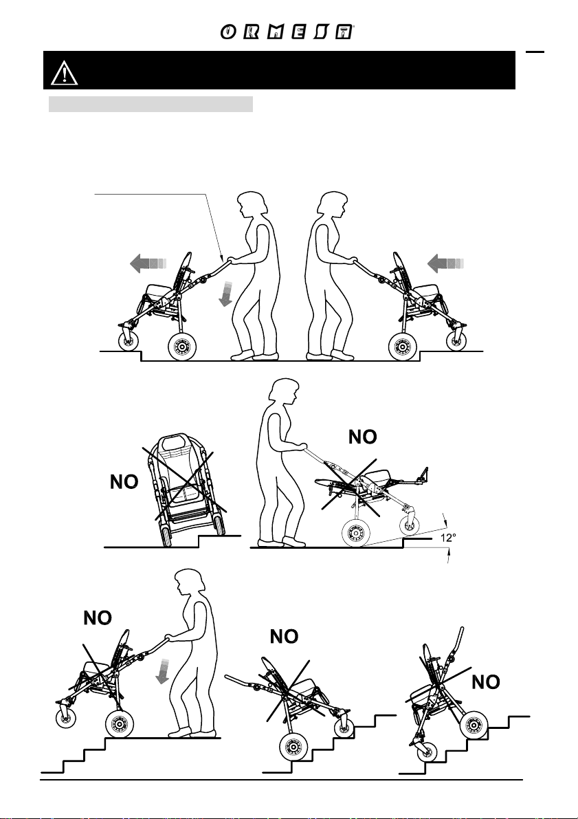
HOW TO TILT THE BUG AND CLIMB UP PAVEMENTS
BUG WITH 4-WHEEL BASE 869
ATTENTION!
ADJUST THE HANDLE (see page 38) TO THE CORRECT HEIGHT FOR THE
ATTENDANT to avoid excessive effort when climbing stairs and facilitate manoeuvres
ADJUSTABLE HANDLEBAR
CLIMB
FACING FORWARD
DESCEND
FACING BACKWARD
11/92
Page 14
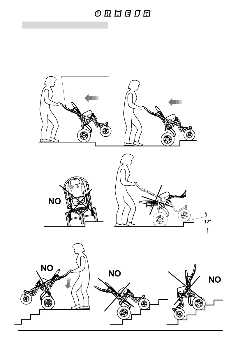
BUG WITH 3-WHEEL BASE 901
ATTENTION!
ADJUST THE HANDLE (see page 46) TO THE CORRECT HEIGHT FOR THE
ATTENDANT to avoid excessive effort when climbing stairs and facilitate manoeuvres
ADJUSTABLE HANDLEBAR
CLIMB
FACING BACKWARD
DESCEND
FACING BACKWARD
12/92
Page 15
HOW TO USE THE BUG 4-WHEEL STROLLER WITH 869
BASE FOR TRANSPORT ON A MOVING VEHICLE (private
cars, buses, etc.)
THE BUG 4-WHEEL STROLLER (seat unit + 869 base) conf orms to the ISO 7176-19 and
ANSI RESNA WC/19 standard, which defines the safety requirements f or transport, facing
in the direction of travel, on moving vehicles (private cars, buses, etc.).
In order to use it safely, carefully read the warnings and fol low the instructions given on
pages from 14 to 17.
THE PUSHCHAIR-SE ATED OCCUPANT MUST FACE THE FRONT OF THE VEHICLE (see
fig. 4, page 16). According to the ISO 7176-19 point 6.3.4, compliance with ISO 7176-19 does
not preclude using the pushchair facing rearward in large accessible vehicles equipped and
approved with rear-facing wheelchair passenger stations
The child shoul d weigh at least 22 kg (48.5 lbs) because the CRASH TEST p rovided by the
ISO and ANSI/RESNA standards only refers to wheelchairs/pushchairs for users whose weight
is 22 kilos or more
THE VEHICLE MUST BE APPROVED FOR TRANSPORTING ORTHOPAEDIC
WHEELCHAIRS/STROLLERS IN CONFORMITY WITH STANDARD ISO 7176-19 (see fig. 4,
page 16)
THE CHILD MUST WE AR BOTH A LAP BELT AND A DIAGONAL SHOULDER BELT ISO
7176-19- OR ISO 10542-APPROVED (i.e., belts with a label of conformity to these ISO
standards). THE USE OF A LAP BELT BY ITSELF IS NOT RECOMMENDED. Postural
belts, such as models 828, 853, 894, 903 and 906 are not type-approved for use as
restraint systems and can only be used in addition
THE STROLLER MUST BE ANCHORED TO THE MOTOR VEHICLE WITH TH E BACKREST
AND THE LEGREST IN THE UPRIGHT POSITION b y: 1) a four-point strap-type tie down
system that complies with ISO 10542-2, supplied by the vehicle and 2) o ur accessor y 891
- set of 4 tie-down hooks (see fig. 1 and 2, page 14; fig. 3, page 15 and fig. 4, page 16)
! ATTENTION!
ORMESA RECOMMENDS THE USE OF A COMPLETE ISO 10542-2-COMPLIANT
“WTORS” SYSTEM, which consists of restraint systems for both the wheelchair and its
occupant
whenever the child is transferred on a seat of the vehicle, the unoccupied pushchair
should be stored in a cargo area or secured in the vehicle during travel
in order to preserve their effectiveness, belt restraints should not be hel d away from the
body by wheelchair components or parts, such as the wheelchair armrests or wheels (see fig
5 and 6, page17)
shoulder-belt restraints should fit over the shoulders (see fig. 5, page 17)
belt restraints s hould be adjusted as tightly as possible, consistent with user comfort, and
belt webbing should not be twisted when in use
in order to reduce the potential of injury to vehicle occupants, during the transport the tray and
all accessories should be removed and secured separately in the vehicle
THE STROLLER MUST BE INSPECTED BY THE MANUFACTURER OR ITS AUTHORIZED
RETAILER OR DISTRIBUTOR BEFORE REUSE FOLLOWING INVOLVEMENT IN ANY TYPE
OF VEHICLE COLLISION
ANY ALTERATION OR SUBSTITUTION OF THE 891 TIEDOWN HOOKS OR STROLLER
PARTS OR COMPONENTS, WITHOUT THE WRITTEN AUTHORIZATION OF ORMESA
SRL, IS FORBIDDEN AND WILL VOID THE MARK AND THE WARRANTY
13/9
Page 16
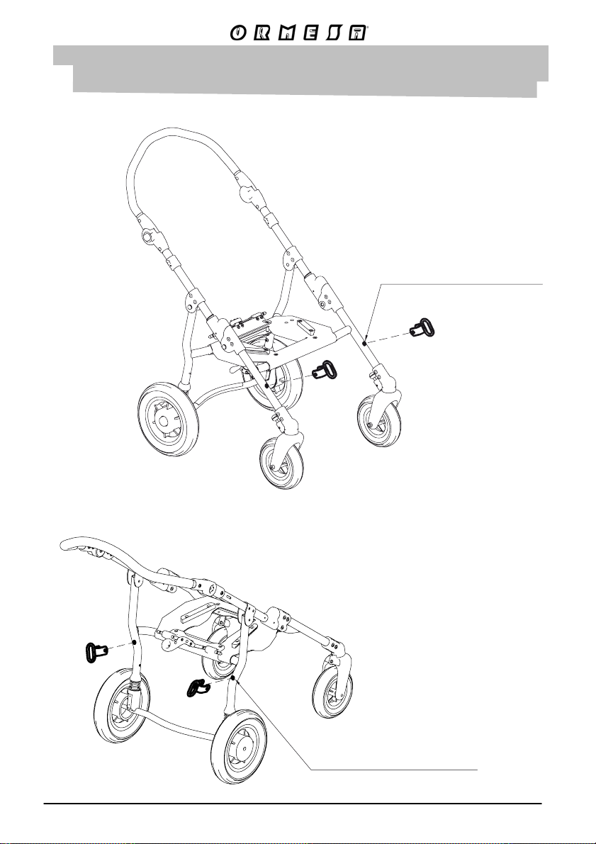
1) POSITION THE 891 TIEDOWN HOOKS (4 RINGS) ON THE POINTS
(NOTCHES) INDICATED ON THE FRAME (only for the 4-wheel 869
base) AND FIX THEM FOLLOWING THE INSTRUCTIONS ON PAGE 15
VIEW FROM THE FRONT
891 SECUREMENT POINTS
FIXING HOLE
VIEW FROM BEHIND
891 SECUREMENT POINTS
FIXING HOLE
14/92
Fig. 1
Fig. 2
Page 17
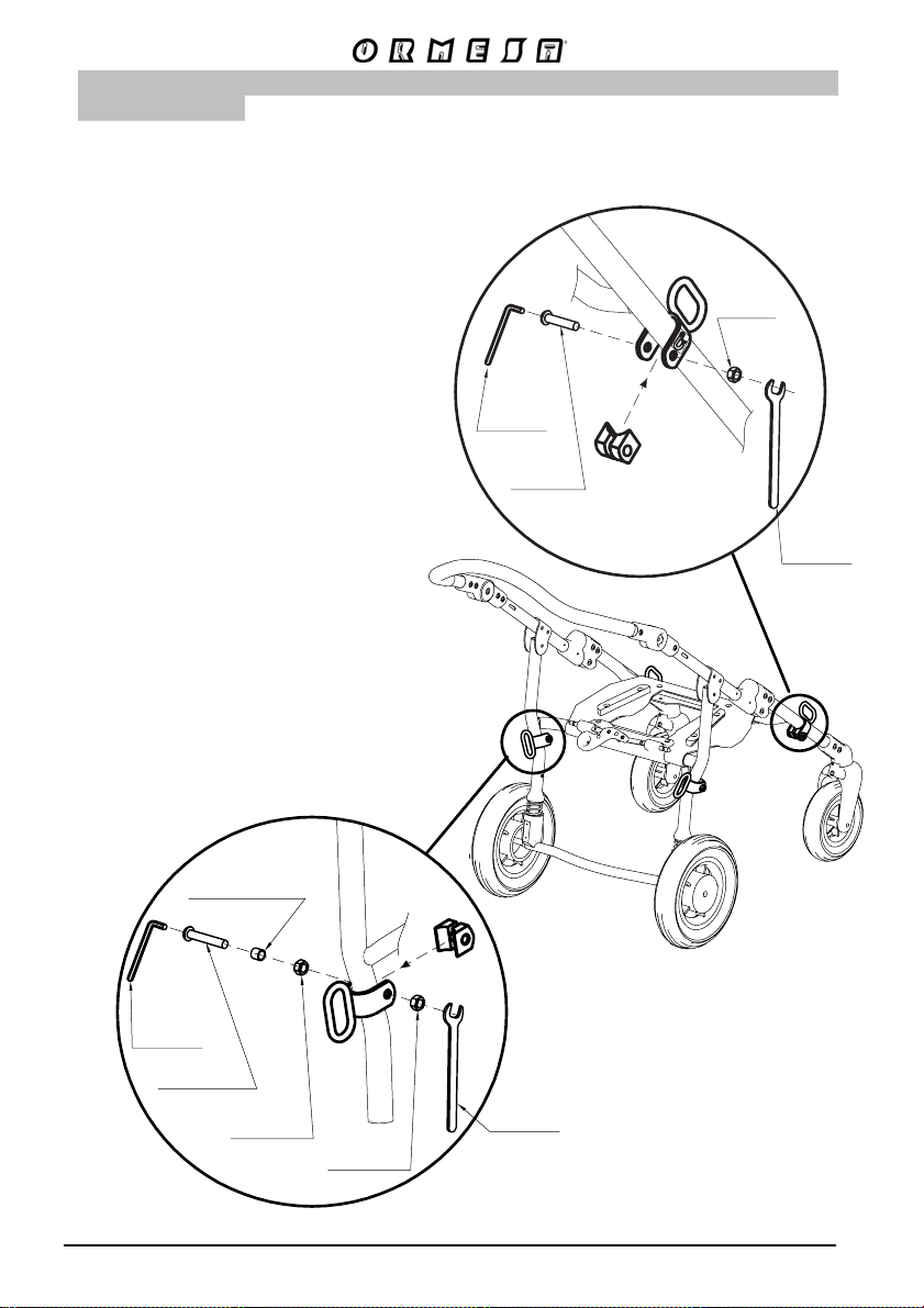
2) HOW TO FIX THE 891 TIEDOWN (4 RINGS) ON THE FRAME (only for 4wheel 869 base)
ATTENTION:
- suitable for ISO 10542-approved four-point
straps provided in the vehicle. To anchor the
stroller to the transport vehicle, see the
instructions on page 16
- the child must wear both a lap belt and a
diagonal shoulder belt ISO 7176-19- or ISO
10542-approved (i.e., belts with a label of
conformity to these ISO standards).
Postural belts, such as models 828, 853, 894,
903 and 906 are not approved for use as
restraint systems and can be only used in
addition
- the vehicle must be suitable for
transporting orthopaedic strollers in
conformity with current law
- read the notices and instructions provided
on page 10 of this use and maintenance
manual. The 891 tiedown hooks are safety
devices and, as such, they must be fixed to
the 869 frame by skilled personnel, such as
the manufacturer or reseller that supplied the
stroller
HEX
WRENCH
SCREW
M8X40
NUT M8
WRENCH
ISO 7176-19 and ANSI RESNA WC/19
CRASH TESTED
PLASTIC
BUSHING
HEX
WRENCH
SCREW M8X55
NUT M8
VIEW FROM BEHIND
WRENCH
Fig. 3
15/92
Page 18
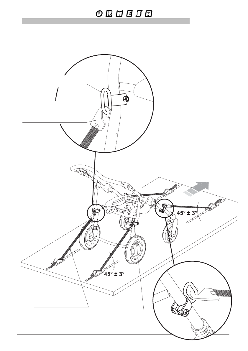
3) HOW THE STROLLER IS TO BE SECURED IN A VEHICLE
HOOK THE APPROVED 4-POINT BELTS OF THE VEHICLE TO THE 891-4 TIEDOWN HOOKS
(4 RINGS) AS SHOWN IN THE FIGURE AND IN THE DIRECTION OF TRAVEL OF THE
VEHICLE
4-POINT STRAP-TYPE TIEDOWN
PUSHCHAIR RESTRAINT
891 TIEDOWN HOOKS
types of tiedown end-fittings
that are compatible with our accessory
891 – set of 4 tiedown hooks
Direction of travel
of the vehicle
Vehicle's ISO 10542-2
belts and hooks
891 TIEDOWN HOOKS
Fig. 4
16/9
Page 19
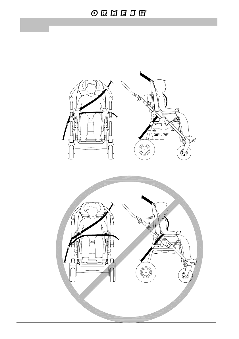
4) THE CORRECT POSITIONING OF OCCUPANT BELT RESTRAINTS ON
THE USER
ATTENTION! the pelvic-belt restraint should be worn low across the front of the pelvis, so that
the angle of the pelvic-belt restraint is within the preferred zone of 30° to 75° to the horizontal,
similar to that shown in Figure 5. A steeper (greater) angle within the preferred zone is
desirable,
ATTENTION! Our belts, straps, vests and harnesses are not intended to be as an occupant
restraint in a moving, but they can be used in addition
YES
beneath
the armrest
and the
frame
NO
above
the armrest
and the
frame
THE INCORRECT PLACEMENT OF BELT RESTRAINTS
FRONT VIEW
17/9
SIDE VIEW
Fig. 5
Fig. 6
Page 20
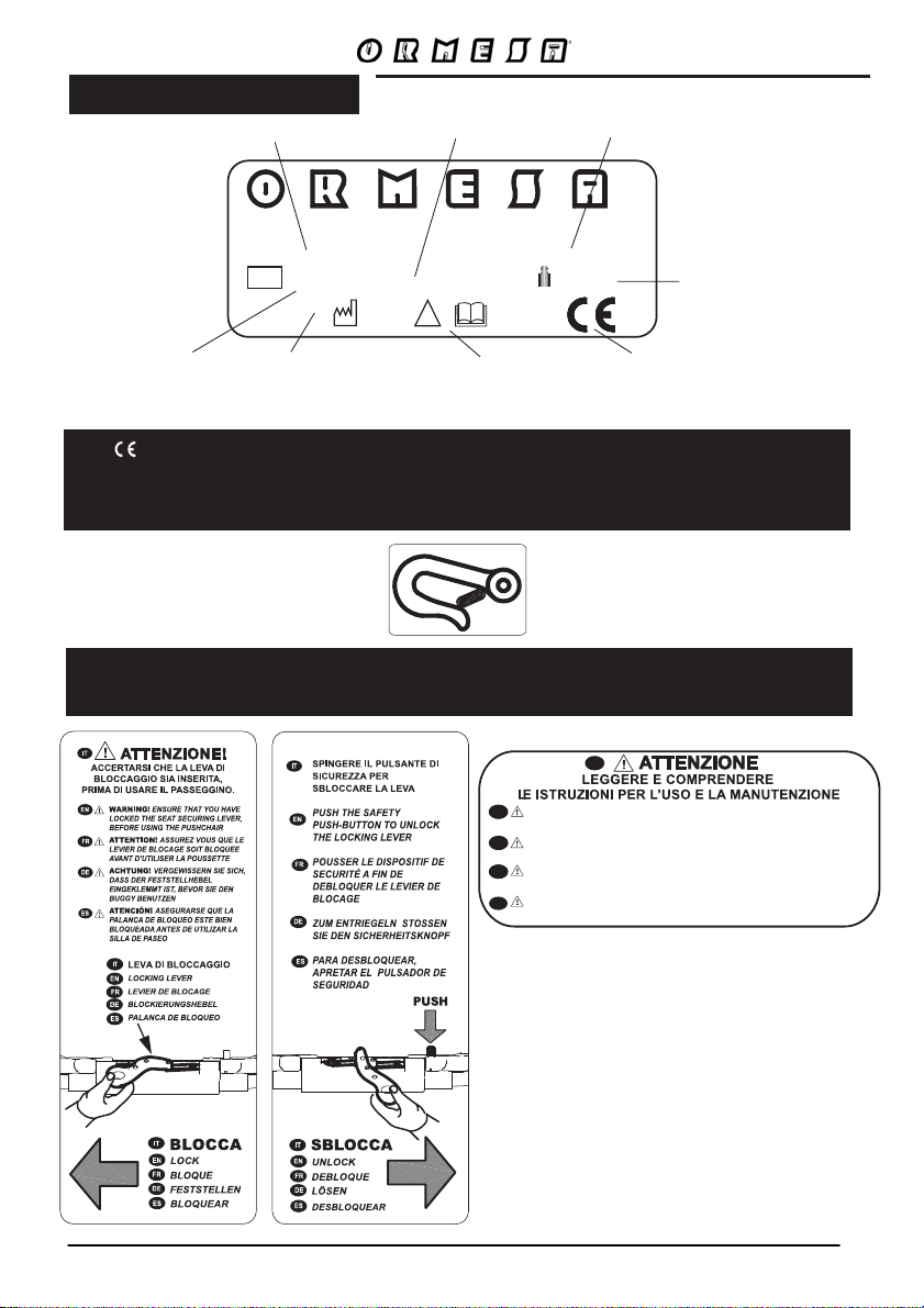
LABELS AND PLATES
Name of the model
Via A. Da Sangallo, 1 06034 Foligno (PG) ITALY Tel. +39 074222927 Fax +39 074222637
MO D E L.
LOT
Series number
S N
!
Article number
®
s.r.l.
PA R T N °
MAX. KG
Max load
LOT code
Date of
production
Warning! Read the
useand maintenance
handbook before use
Conformity with the
European safety
standards
THE MARK CERTIFIES THAT THE BUG SEATWITH BASES 856, 869 AND 901 CONFORMS
TO THE SAFETY REQUIREMENTS OF THE EUROPEAN UNION AND, IN PARTICULAR, TO
THE 93/42/EEC DIRECTIVE ON “MEDICAL DEVICES” AND SUBSEQUENT MODIFICATIONS
AND SUPPLEMENTS
SECUREMENT POINT FOR THE ANCHORAGE OF THE ISO 10542-2 APPROVED 4-POINT STRAPTYPE TIEDOWNS SUPPLIED BY THOSE VEHICLES WHICH ARE SUITABLE FOR TRANSPORTING
ORTHOPEDIC PUSHCHAIRS IN COMPLIANCE WITH THE ISO 7176-19 STANDARD
IT
EN
WARNING! READ AND UNDERST AND THE USE AND
MAINTENANCE INSTRUCTIONS
FR
ATTENTION! LIRE ET COMPRENDRE LES INSTRUCTIONS POUR
L’UTILISATION ET L’ENTRETIEN
DE
SORGFÄLTIG !BITTE LESEN SIE DIE GEBRAUCHSANWEISUNG
SORGFÄLTIG DURCH UND BEACHTEN SIE DIE ENTSPRECHENDEN HINWEISE
ES
! LEER Y COMPRENDER LAS INSTRUCCIONES DE USO
ATENCIóN
Y MANTENIMIENTO
18/9
Page 21
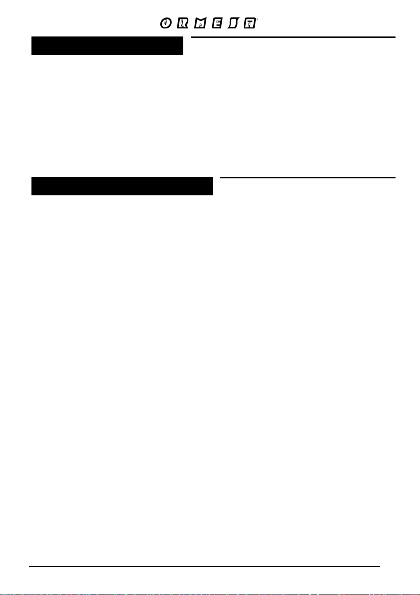
WHAT Bug IS
Bug is a postural seat unit designed for children with disabilities - especially ICP - that
GROWS WITH THE CHILD, TILTS and CAN BE PLACED ON 3 BASES:
- outdoor 4-wheel base 869;
- outdoor 3-wheel base 901
- indoor adjustable base 856.
THE POSTURAL POSITION set, even with the tilting seat, is MAINTAINED ON ALL THE
SUPPORT BASES
TECHNICAL FEATURES
- FRAME foldable, lightweight (aluminium), with a narrow base, easy to push and maneuver
(compact, its wheels do not protrude from the 4-wheel-base). Sturdy and durable, has passed
all stability/fatigue and safety tests, required by the international laws, in specialized centres
(TÜV-Germany, CERAH-France, TRL-UK).
- BACKREST rigid, retentive and able to recline of 40°. Its hinge coincides with the user's hip
physiological fulcrum, so as to avoid that, during the adjustment, the reclining movement causes
the user sliding forward. Height-adjustable by 10 cm (size onetwo) and 15 cm (size threefour).
With slots for inserting the accessories.
- HEADREST incorporated into the backrest, so that the child’s head is always supported during
the tilt adjustments of the seat and of the backrest, even without accessories.
- SEAT width and depth adjustable by 10 cm in each direction. Reversible (size onetwo)
- TILT-IN-SPACE SYSTEM INCORPORATED IN THE SEAT so that, after removing or
transfering the seat, it is not needed to reposition the posture. SAFE because adjustments can
be easily operated by the carer with one only hand, without effort. COMFORTABLE because the
tilting movement is continuous, without jerks. Size onetwo can be tilted from 0° to 35°; size
threefour from 7° to 30°.
- LEGREST adjustable in height and tilt. The hinge coincides with the child’s knee physiological
fulcrum, so as to avoid that the legrest movement may cause any sliding or change of posture of
the child.
- FOOTREST tip-up and flexion-extension adjustable.
- CUSHION padded, ergonomic, removable for machine washing a nd attachable to the seat with
press studs. It is resistant to wear and tear, fire-retardant conforming to the UNI 9177 standard.
Designed to allow positioning /adding or removing all accessories while the child is seated. It is
bright & fashionable and adapts to the growth of the frame.
- punc ture proof WHEELS. Outdoor base 869: front 17 cm; back 25 cm (size onetwo), 30 cm
(size threefour). Outdoor base 869: front 17 cm, back 30 cm. With independent drum brakes,
directional locks and shock absorbers; light and easy to push on every surface. Feeding base
for indoor use 869, adjustable in height: 10 cm swivelling, with brakes.
- 4 SIZES in 2: the seat unit grows with a child.
19/9
Page 22
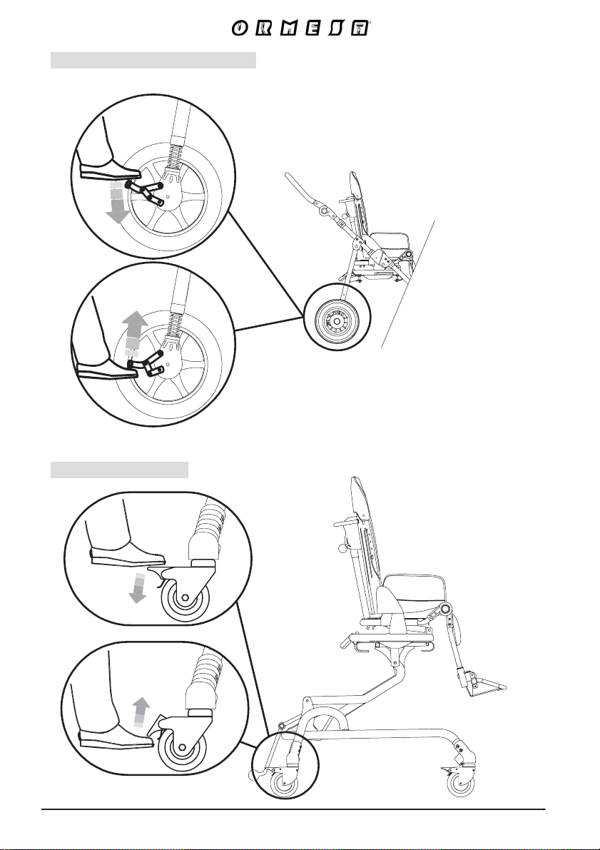
Base 869 and 901 BRAKING
LOCKS
UNLOCKS
GNIKARB 658 esaB
LOCKS
UNLOCKS
20/9
Page 23
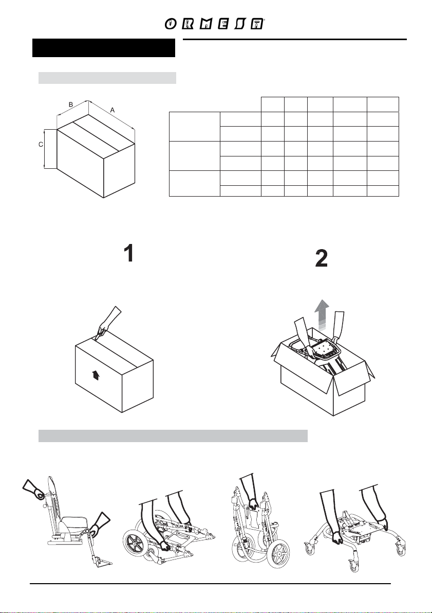
INITIAL PREPARATION
A
V
PACKAGING INFORMATION
REMOVING Bug FROM THE BOX
BUG
with BASE
869
BUG
with BASE
901
BUG
with BASE
856
OLUME
WEIGHT
cmBcmCcm
Size 1-2 95 65 48 0.296 24
Size 3-4 75 65 103 0.502 32
Size 1-2 70 60 95 0.399 26
Size 3-4 75 65 110 0.536 28
Size 1-2 75 65 68 0.331 30
Size 3-4 75 65 88 0.429 35
3
m
kg
CUT WITHOUT PRESSING TOO HARD WITH
ATTENTION!
THE BLADE SO AS NOT TO DAMAGE THE
CONTENTS OF THE BOX
REMOVE THE SEAT FROM
THE BOX AND THEN THE
FRAME
HOW and WHERE TO HOLD the COMPONENTS of BUG
Seat unit Base 869 Base 901 Base 856
21/9
Page 24
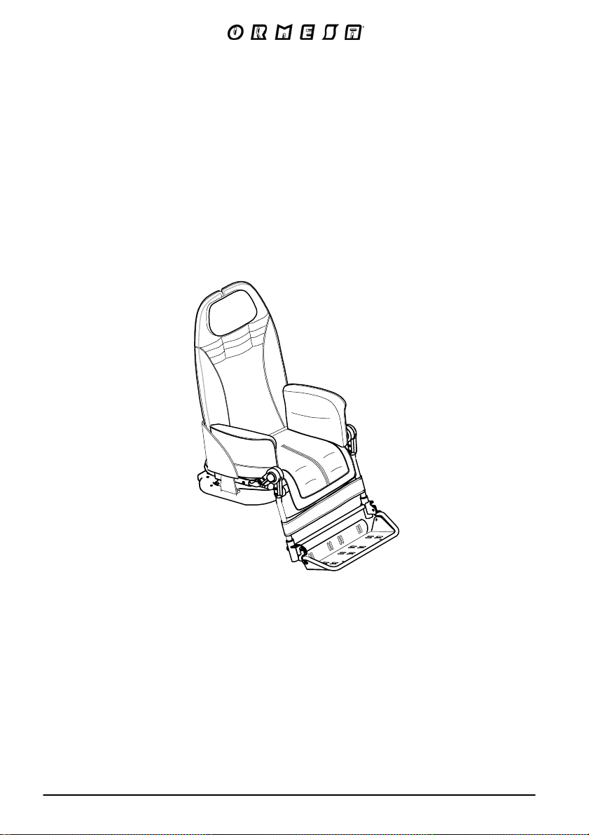
Bug SEAT UNIT
THE ADJUSTMENTS HEREINAFTER SPECIFIED ARE
FOR THE SEAT UNIT ON THE 869, 901 and 856 base
22/9
Page 25
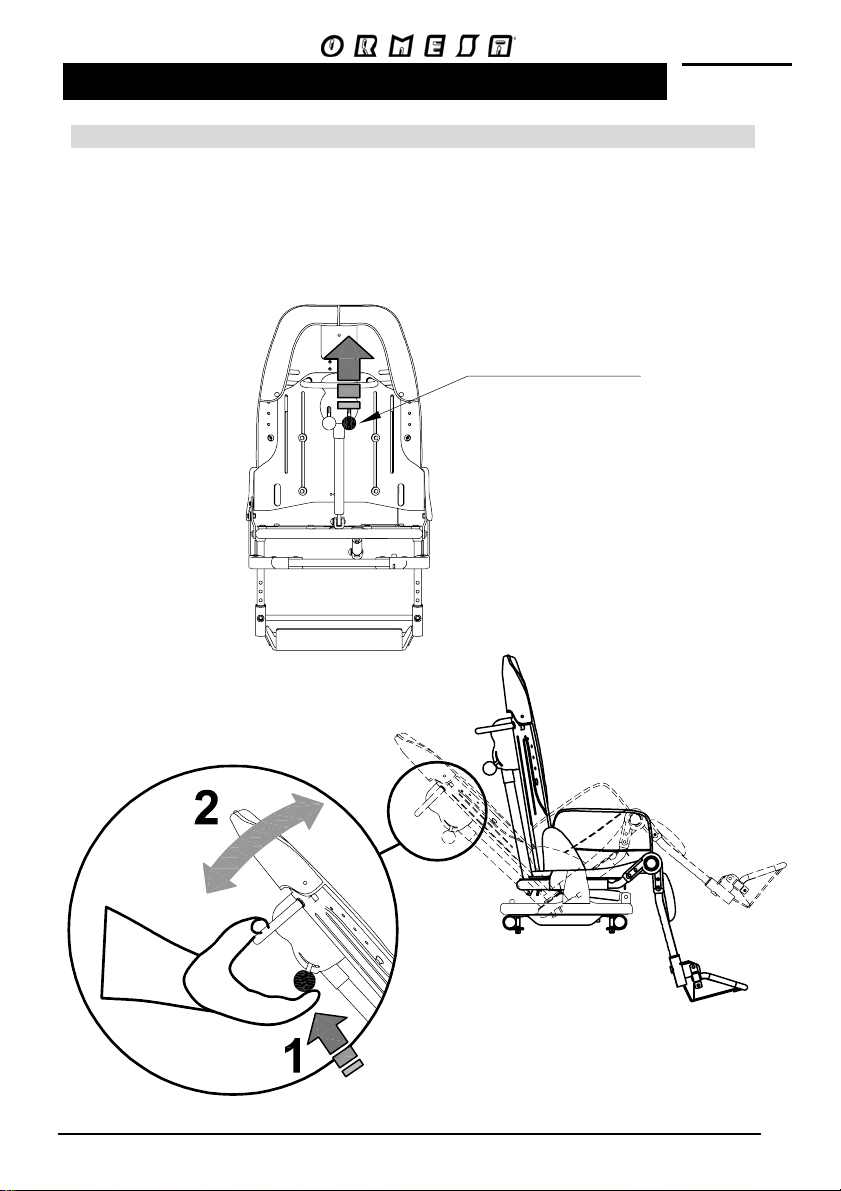
SEATING UNIT ADJUSTMENTS ON BASES 869, 901 AND 856
ADJUSTING THE INCLINATION OF THE SEAT (TILT-IN-SPACE SYSTEM)
1. PULL UP THE RED KNOB
2. TILT THE SEAT KEEPING THE KNOB PULLED AND RELEASE IT WHEN ADJUSTED TO
THE DESIRED POSITION
VIEW FROM BEHIND
RED KNOB
FOR ADJUSTING THE INCLINATION
OF THE SEAT
23/9
Page 26
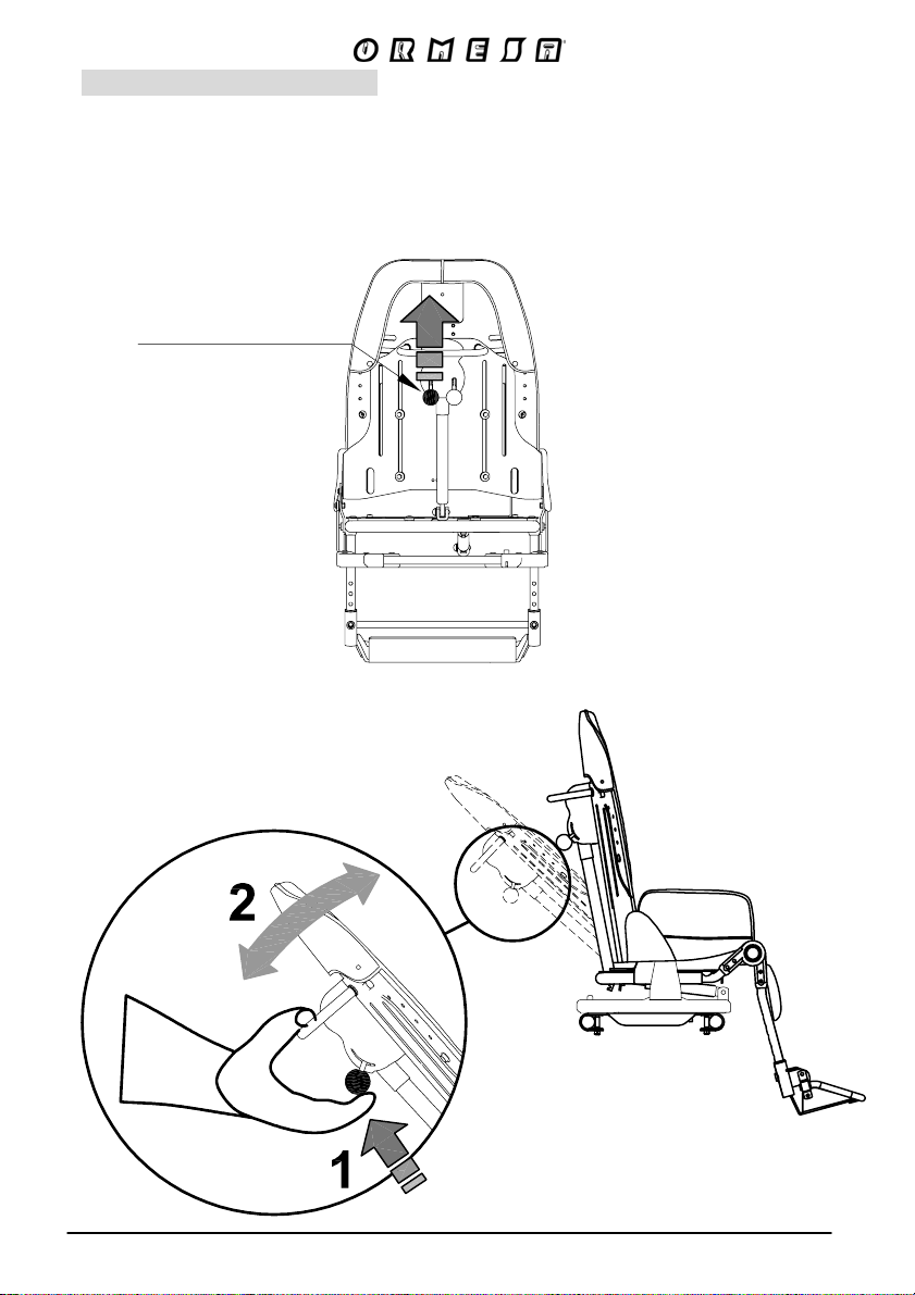
RECLINING THE BACKREST
1. PULL UP THE BLACK KNOB
2. RECLINE THE BACKREST, KEEPING THE KNOB PULLED AND RELEASE IT WHEN THE
BACKREST HAS REACHED THE DESIRED POSITION
VIEW FROM BEHIND
BLACK KNOB
FOR ADJUSTING THE
RECLINING BACKREST
24/9
Page 27
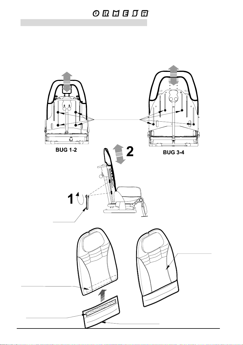
ADJUSTING THE HEIGHT OF THE BACKREST
- LOOSEN THE FOUR SCREWS LOCATED ON THE REAR OF THE BACKREST WITH THE
PROVIDED WRENCH
- SLIDE THE BACKREST TO THE DESIRED POSITION
- TIGHTEN THE SCREWS
- FIX THE EXTENSION OF THE BACKREST CUSHION
VIEW FROM BEHIND
BACKREST
ADJUSTMENT
4 SCREWS
VIEW FROM BEHIND
WRENCH
BUTTONHOLE VELCRO
ON THE BACK OF THE CUSHION
HOOK VELCRO
EXTENSION OF
THE BACKREST CUSHION
25/9
EXTENDED
BACKREST CUSHION
Page 28
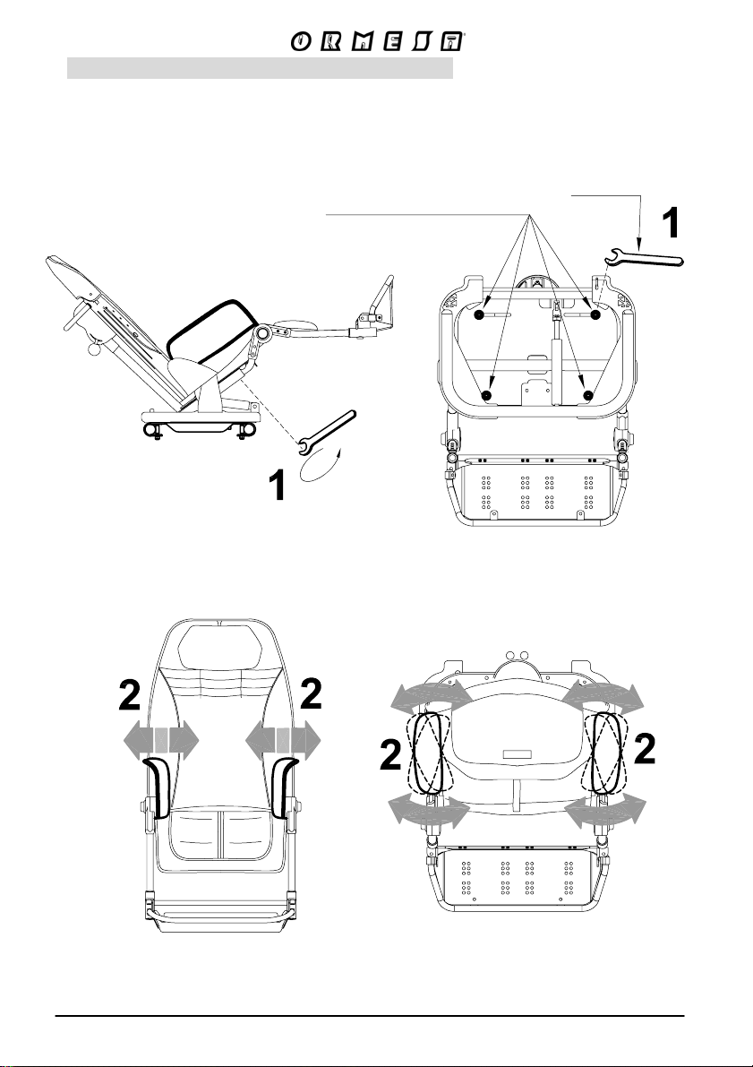
ADJUSTING THE WIDTH OF THE SEAT BASE
SEAT
ADJUSTMENT
4 SCREWS
WRENCH
VIEW FROM BELOW
26/9
VIEW FROM ABOVE
Page 29
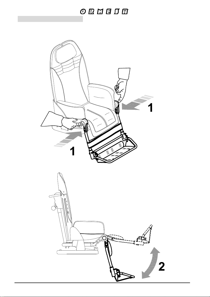
ADJUSTING THE LEGREST
PRESS BOTH BUTTONS AT THE SAME TIME TO ADJUST THE TILT OF THE LEG SUPPORT
27/9
Page 30
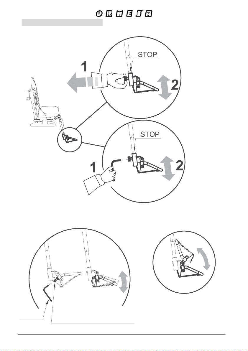
ADJUSTING THE FOOTREST
a) In height
SIZE 1-2
SIZE 3-4
b) in tilt c) in tipping up
WRENCH
SCREW FOR ADJUSTING
THE TILT OF THE FOOTREST
28/9
Page 31
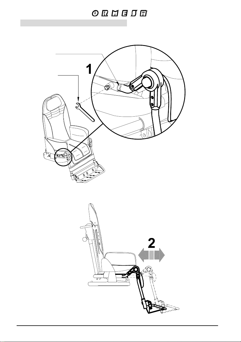
ADJUSTING THE DEPTH OF THE SEAT
END OF TRAVEL STOP
WRENCH
29/9
Page 32
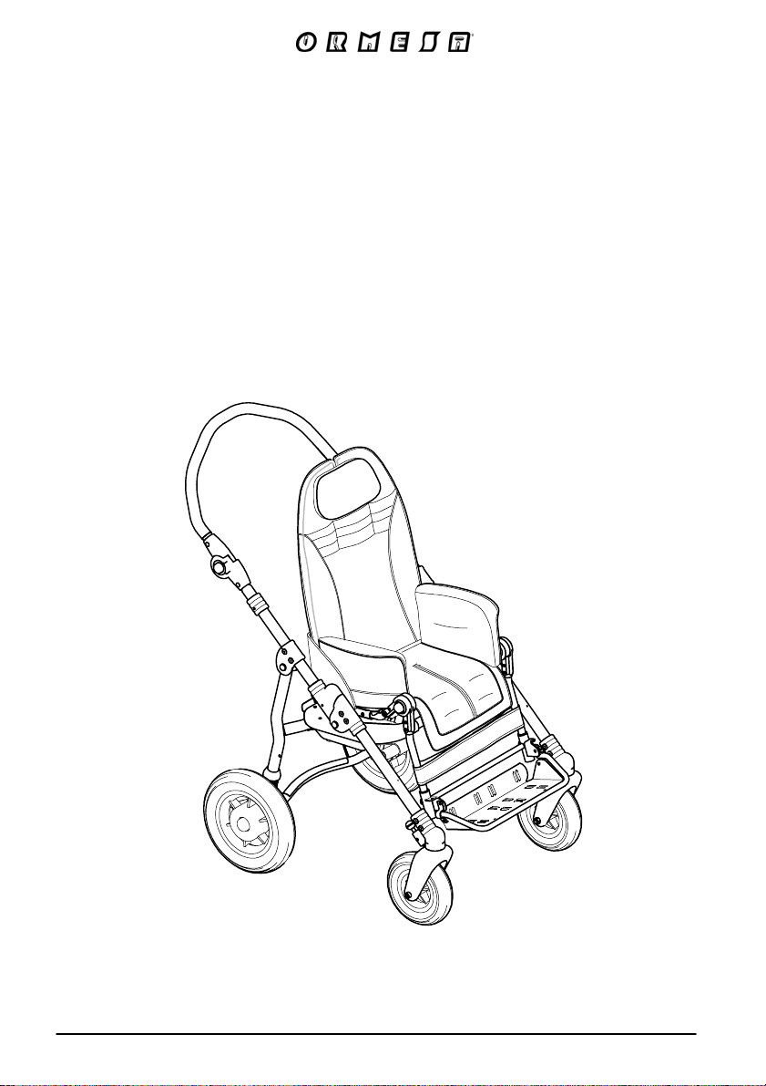
Bug seat
with 4-WHEEL base
869
30/9
Page 33
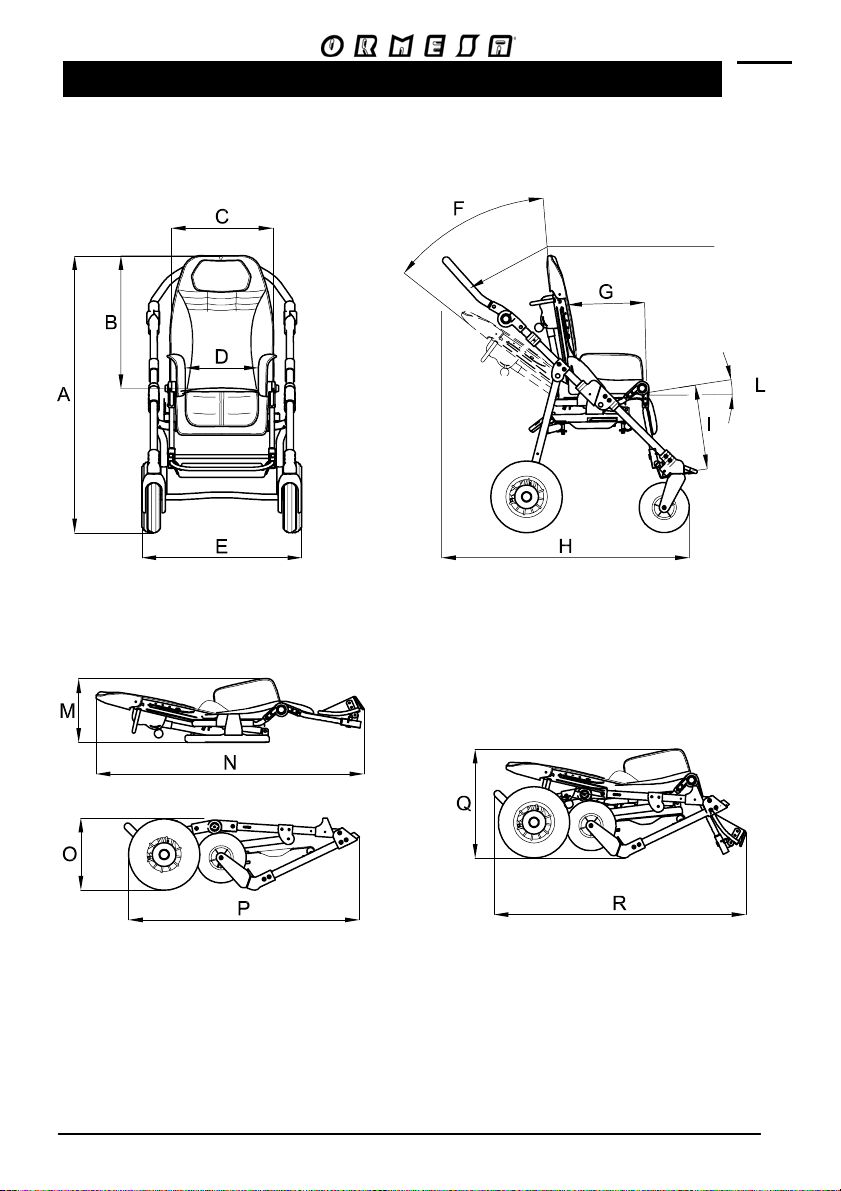
TECHNICAL SPECIFICATIONS of Bug with four wheel BASE 869
HANDLE ADJUSTABLE
180°
Stroller closed
with seat removed
Stroller closed
with seat attached
- WHEELS:
front, with direction locks, 17 cm (7 Inches);
rear, with shock absorbers, 25 cm (10 Inches) (sizes 1-2), 30 cm (12 Inches) (size 3-4)
- BRAKES independent parking brakes
31/92
Page 34
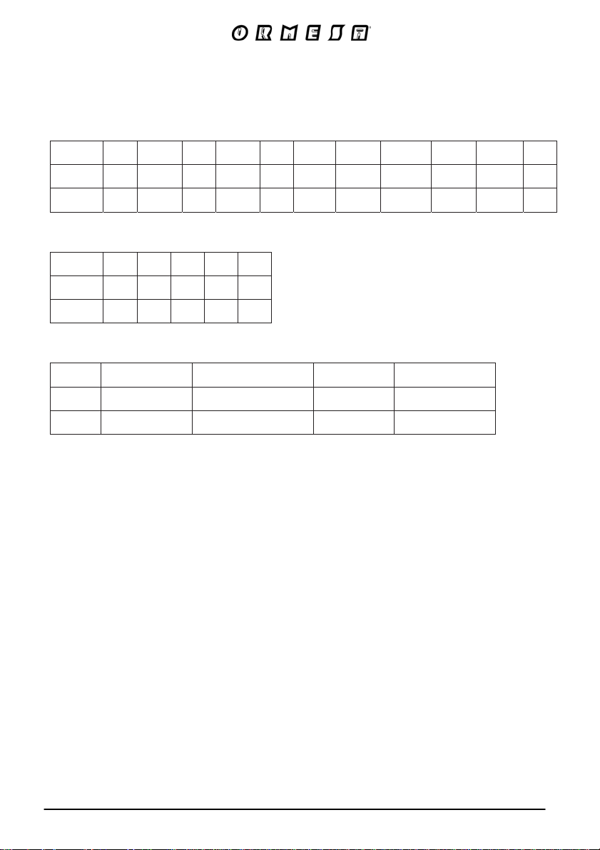
The numbers divided by the dash specify a minimum and a maximum adjustment
Measures in cm and kilos
size
A
(cm) B (cm) C (cm)D (cm)E (cm)
F G
(degree) (degree)
(cm)
H
(cm)
(cm)
I
L M
1-2 102 52-62 37 20-30 57 40° 20-30 66-92 18-30 0°-35° 29
3-4 112 60-75 44 25-36 62 40° 30-40 82-106 30-40 7°-30° 34
size
N
(cm) O (cm) P (cm)Q (cm)R (cm)
1-2 88 29 82 44 81
3-4 112 36 91 52 94
Weight of the frame Weight of the seat Total weight Max load
size
(kg) (kg) (kg) (kg)
1-2 9,5 8,5 18 35
3-4 10,5 11,5 22 45
(cm)
32/9
Page 35
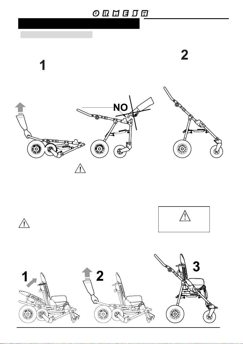
HOW TO USE Bug WITH BASE
OPENING the STROLLER
a) WITHOUT THE SEAT
PULL THE HANDLE
UPWARDS
CLOSING
LOCK
MAKE SURE THE
FRAME IS LOCKED
A CLICK MEANS THAT
THE FRAME IS SECURELY OPEN
b) WITH THE SEAT ATTACHED
POSITION THE BACKREST VERTICALLY
BEFORE OPENING THE STROLLER
HEAVY
33/92
Page 36
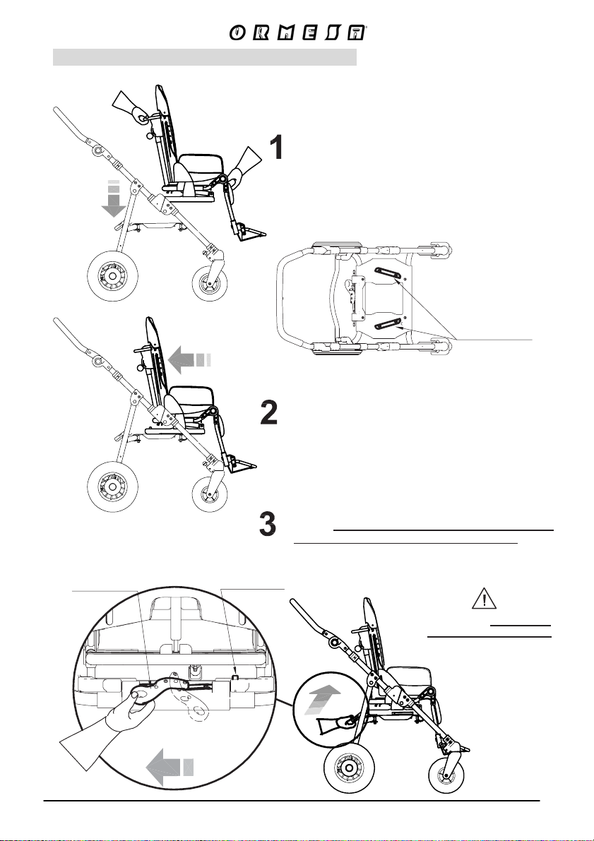
HOW TO ATTACH THE SEAT TO THE FRAME
AFTER APPLYING BRAKES, PLACE
THE SEAT ON THE MOUNTING
VIEW FROM ABOVE THE FRAME
FIG. A
PLATE (Fig. A)
MOUNTING
PLATE
PUSH THE SEAT BACKWARDS SLIDING IT
ON TO THE MOUNTING PLATE
OPERATE THE LOCKING LEVER. (AS IN
FIG. B) THE CLICK OF THE SAFETY RED PUSHBUTTON MEANS THAT IS WELL LOCKED
LOCKING
LEVER
FIG. B
LOCKS
VIEW
FROM BEHIND
PUSH-BUTTON
UNLOCKS
DER YTEFAS
MAKE SURE THE SEAT IS
IN THE MOUNTING PLATE
BEFORE LOCKING IT WITH
THE LEVER
34/92
Page 37
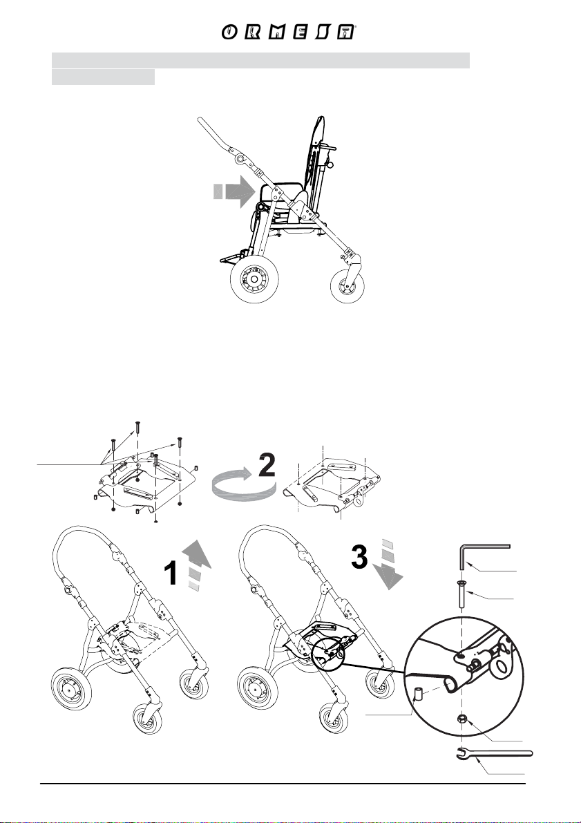
HOW TO REVERSE THE SEAT SO THAT THE CHILD FACES HIS
MOTHER (FIG. A)
(ONLY FOR SIZE 1-2, THE SIZE 3-4 SEAT IS NOT REVERSIBLE)
FIG. A
1- REMOVE THE SEAT-SUPPORT BY UNSCREWING THE FOUR SCREWS
2- TURN THE SEAT-SUPPORT BY 180°
3- FIX THE SEAT-SUPPORT ON THE FRAME AND TIGHTEN THE FOUR SCREWS
INSURING THAT THE FOUR BUSHINGS ARE WELL PLACED (SEE FIG. B)
REMOVE THE
FOUR SCREWS
35/92
WRENCH
SCREW
BUSHING
NUT
FIG. B
WRENCH
Page 38
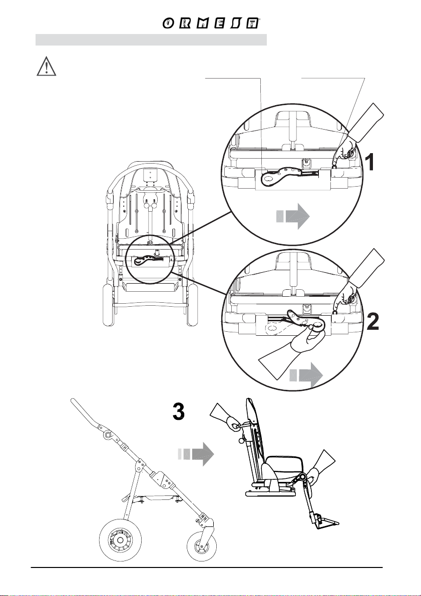
HOW TO DETACH THE SEAT FROM THE FRAME
FIRST APPLY BRAKES
1- NOTTUB-HSUP DER YTEFAS EHT SSERP
2- AT THE SAME TIME TURN THE LOCKING
LEVER FROM LEFT TO RIGHT
3- SLIDE THE SEAT FORWARD
VIEW FROM BEHIND
LOCKING LEVER
DER YTEFAS
PUSH-BUTTON
SKCOL UNLOCKS
SKCOL UNLOCKS
36/92
Page 39
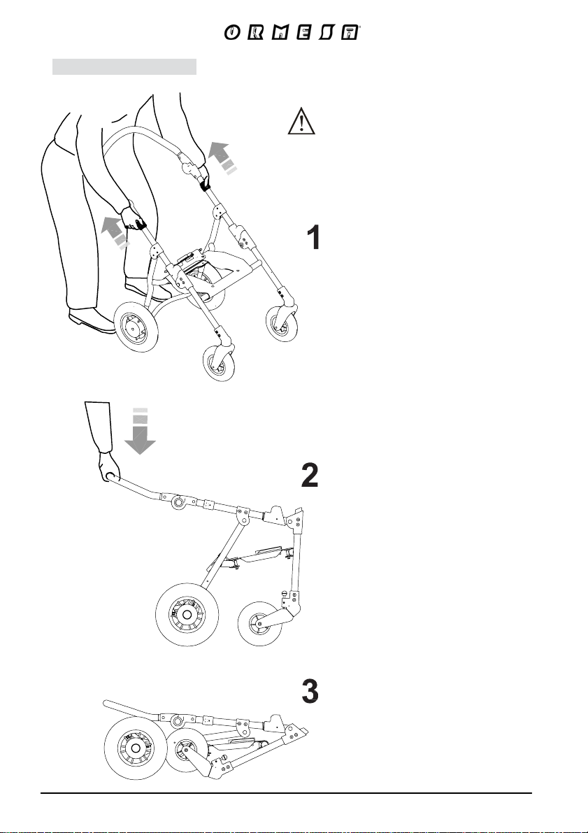
FOLDING THE BASE
WE SUGGEST THAT YOU FOLD THE BASE
WITHOUT THE SEAT
PULL THE BLACK LOCKS WITH
BOTH HANDS
GENTLY PULL THE
HANDLE DOWNWARD
37/92
FRAME CLOSED
Page 40
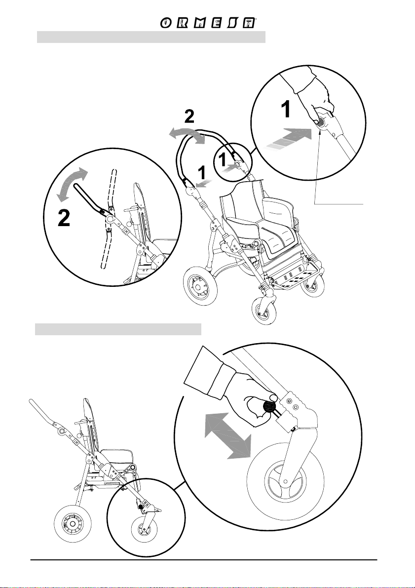
ADJUSTING THE INCLINATION OF THE HANDLE
IT FACILITATES THE ENTRANCE INTO THE ELEVATOR AND ITS TRANSPORT INTO THE CAR
RED BUTTON
FRONT WHEEL DIRECTION LOCKS
38/92
Page 41
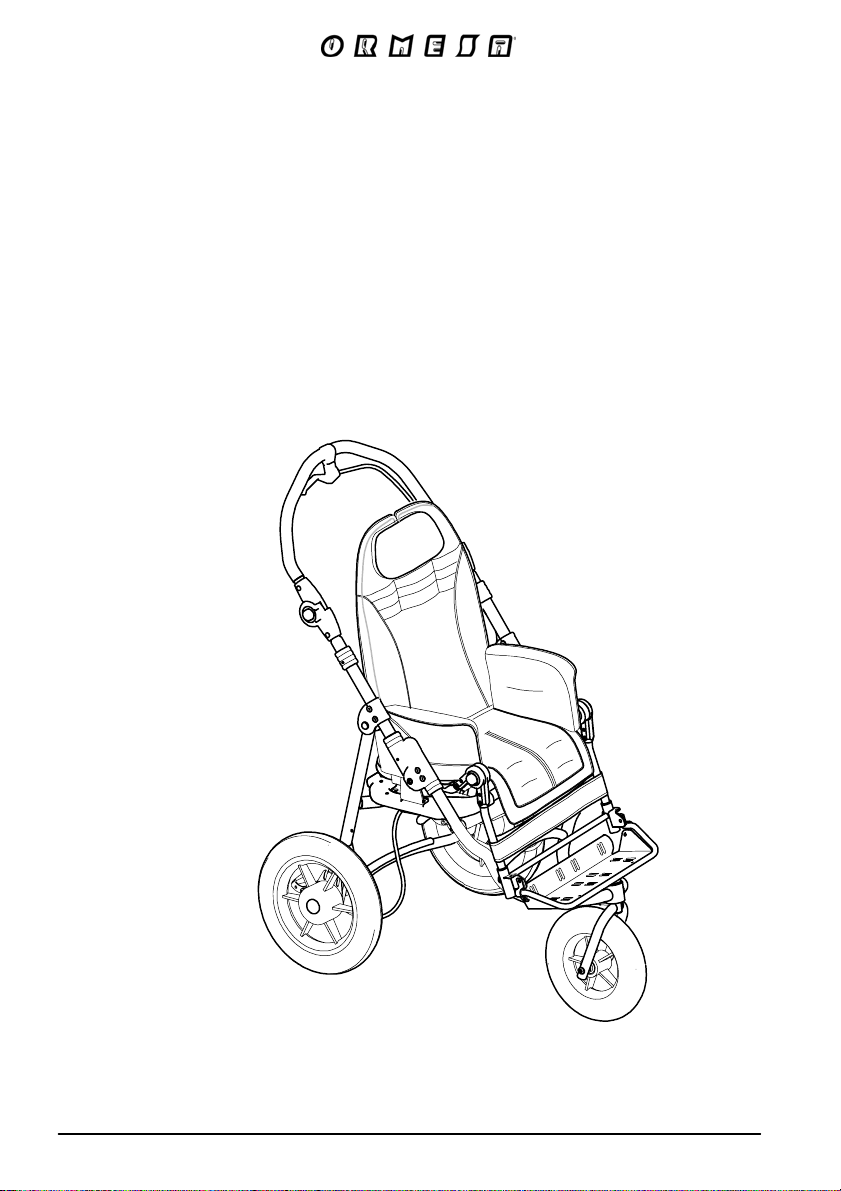
Bug seat
with 3-WHEEL base
901
39/92
Page 42
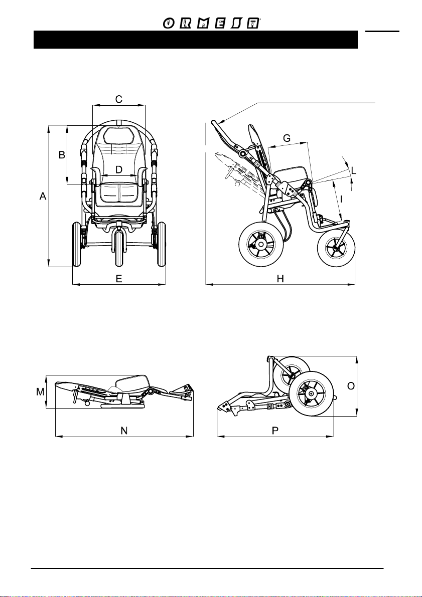
TECHNICAL SPECIFICATIONS of Bug with 3 wheels BASE 901
Push handle 180° adjustable
Stroller closed
with seat removed
- WHEELS :
front, with direction lock, 25 cm (10 Inches);
rear, with shock absorbers, 30 cm (12 Inches)
- BRAKES independent parking brakes
- HAND BRAKE (allows slowing the stroller on downhill slopes or while jogging!)
40/92
Page 43
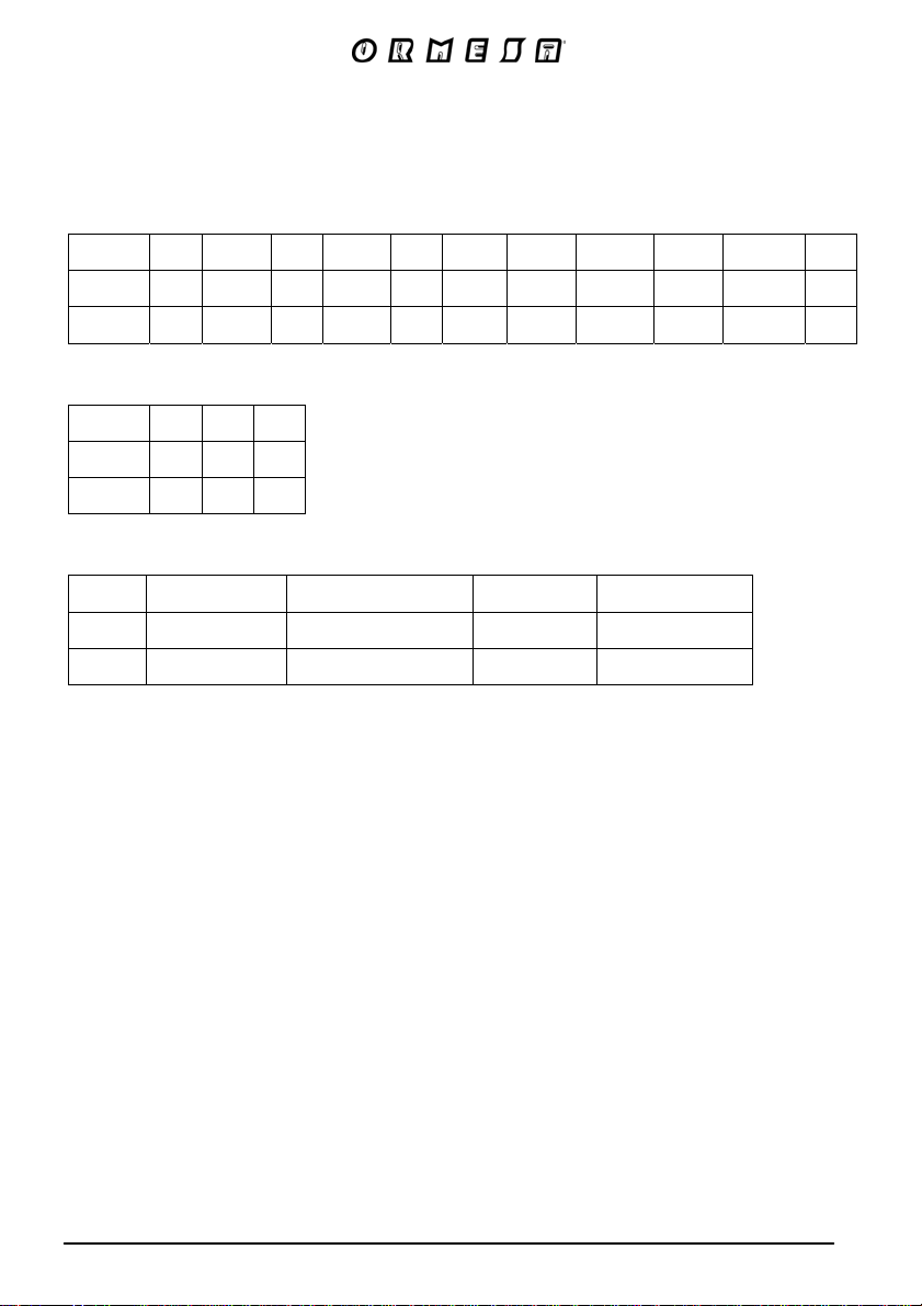
The numbers divided by the dash specify a minimum and a maximum adjustment
Measures in cm and kilos
size
A
(cm) B (cm) C (cm)D (cm)E (cm)
F G
(degree)
(cm)
H
(cm)
(cm)
I
L M
(degree)
(cm)
1-2 112 52-62 37 20-30 63 40° 20-30 78-104 18-30 14°-49° 35
3-4 122 60-75 44 25-36 69 40° 30-40 98-127 30-40 15°-38° 50
size
N
(cm) O (cm) P (cm)
1-2 88 38 79
3-4 112 40 96
size
Weight of the frame Weight of the seat Total weight Max load
(kg) (kg) (kg) (kg)
1-2 10,5 8,5 19 35
3-4 11,5 11,5 23 45
41/92
Page 44
HOW TO USE Bug WITH BASE 901
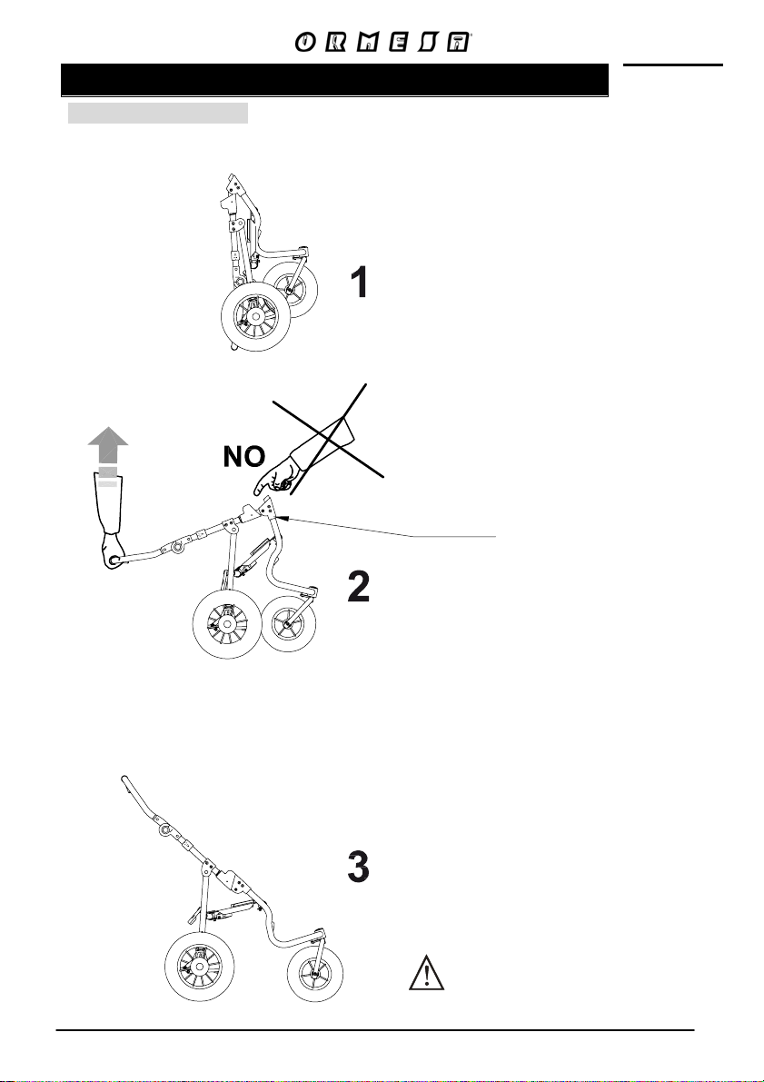
OPENING THE BASE
PUT THE BASE IN THE VERTICAL
POSITION
CLOSING
LOCK
PULL THE HANDLE
UPWARDS
A CLICK MEANS THAT
THE FRAME IS SECURELY OPEN
MAKE SURE
THE FRAME IS LOCKED
42/92
Page 45
HOW TO ATTACH THE SEAT TO THE FRAME
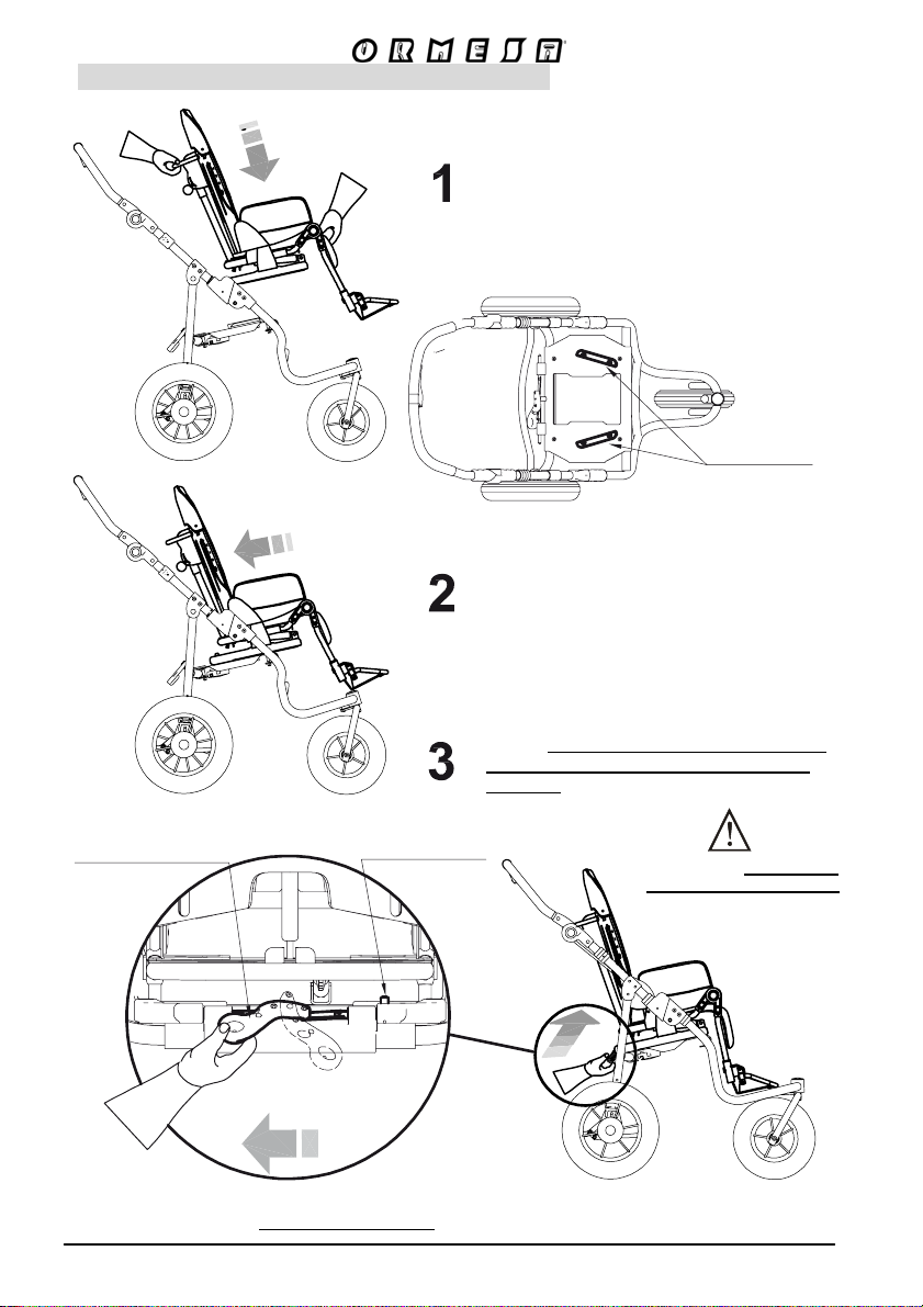
AFTER APPLYING BRAKES, PLACE THE
SEAT ON THE MOUNTING PLATE (Fig.
A)
LOCKING LEVER
VIEW
FROM BEHIND
SAFETY RED
PUSH-BUTTON
VIEW FROM ABOVE THE FRAME
FIG. A
MOUNTING
PLATE
PUSH THE SEAT BACKWARDS SLIDING
IT ON TO THE MOUNTING PLATE
OPERATE THE LOCKING LEVER. (AS IN
FIG. B) THE CLICK OF THE SAFETY RED
PUSH-BUTTON MEANS THAT IS WELL
LOCKED
MAKE SURE THE SEAT IS
IN THE MOUNTING PLATE
BEFORE LOCKING IT WITH
THE LEVER
LOCK
UNLOCK
FIG. B
THE SEAT IS NOT REVERSIBLE WITH THE OUTDOOR 3-WHEEL 901 BASE
43/92
Page 46
HOW TO DETACH THE SEAT FROM THE FRAME
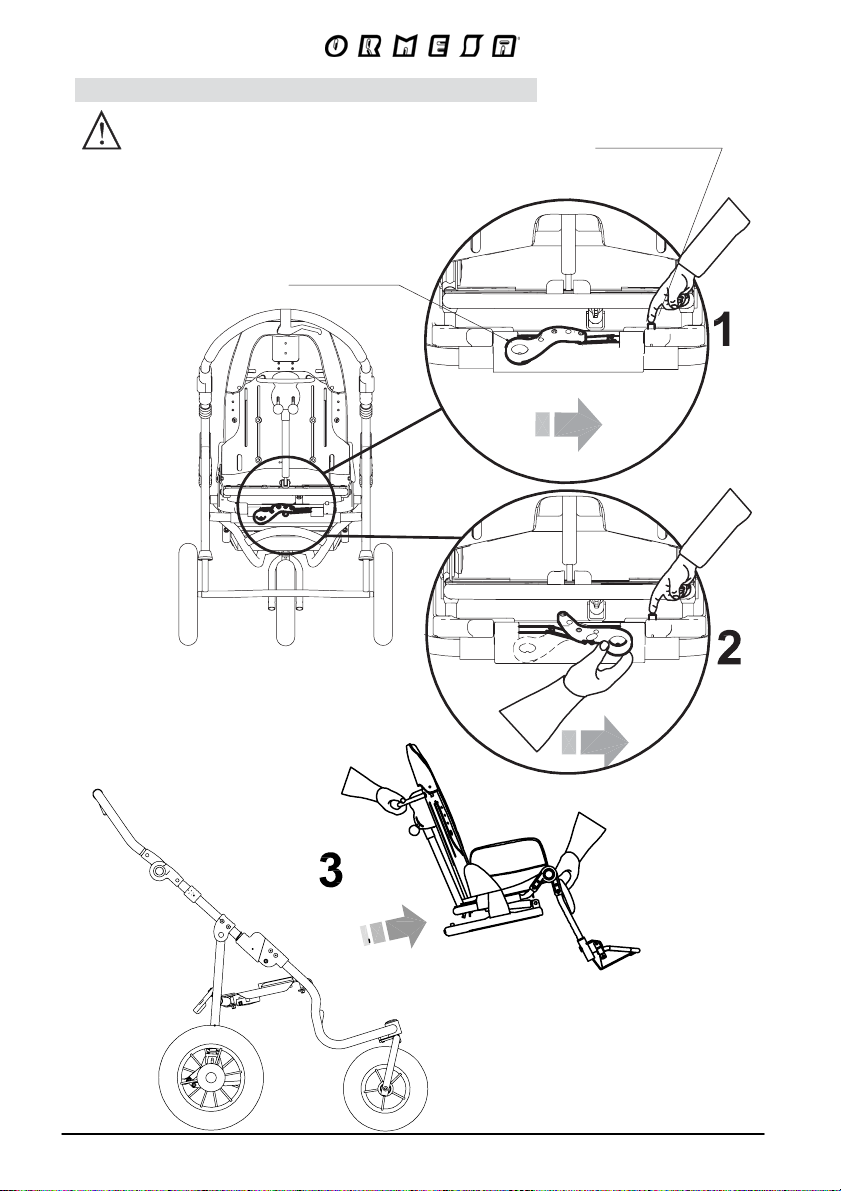
FIRST APPLY BRAKES
1- PRESS THE SAFETY RED PUSH-BUTTON
2- AT THE SAME TIME TURN THE LOCKING LEVER
FROM LEFT TO RIGHT
3- SLIDE THE SEAT FORWARD
LOCKING LEVER
SKCOL UNLOCKS
DER YTEFAS
PUSH-BUTTON
VIEW FROM BEHIND
SKCOL UNLOCKS
44/92
Page 47
FOLDING THE BASE
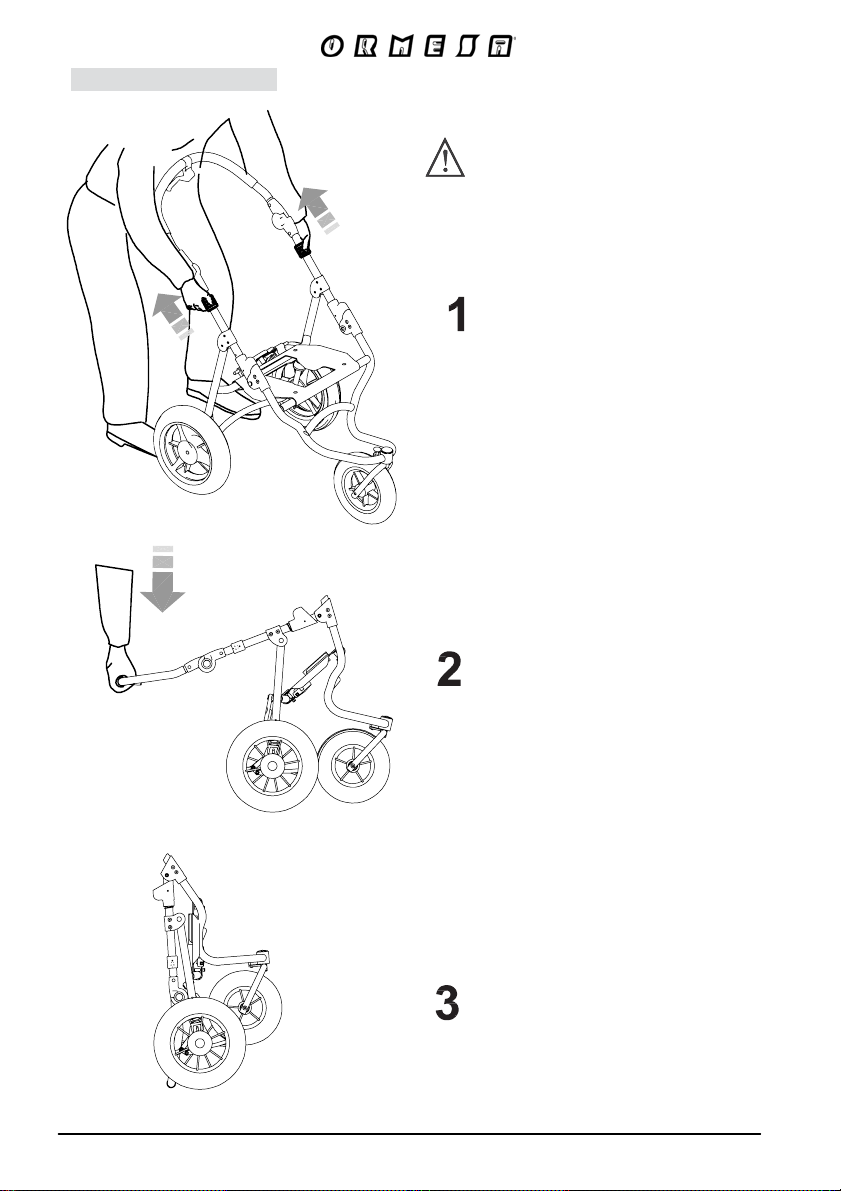
WE SUGGEST THAT YOU FOLD THE BASE
WITHOUT THE SEAT
PULL THE BLACK LOCKS WITH BOTH
HANDS
45/92
GENTLY PULL THE HANDLE
DOWNWARD
FRAME CLOSED
Page 48
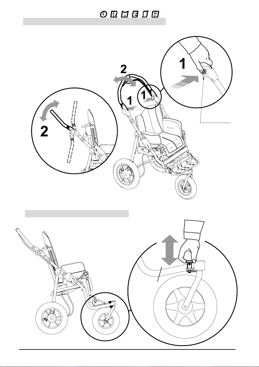
ADJUSTING THE INCLINATION OF THE HANDLE
IT FACILITATES THE ENTRANCE INTO THE ELEVATOR AND ITS TRANSPORT INTO THE CAR
RED BUTTON
FRONT WHEEL DIRECTION LOCKS
46/92
Page 49
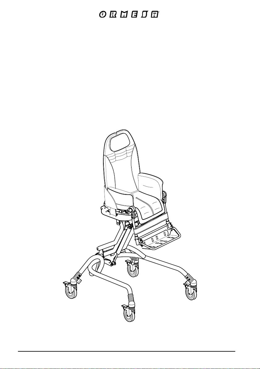
Bug seat
with INDOOR base
856
47/9
Page 50
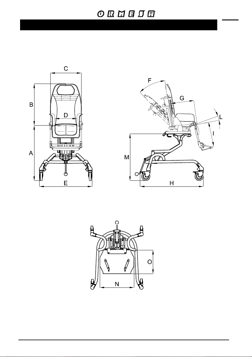
TECHNICAL SPECIFICATIONS of Bug with BASE 856
- WHEELS, 10 cm (4 Inches), swivelling with brakes.
48/9
Page 51
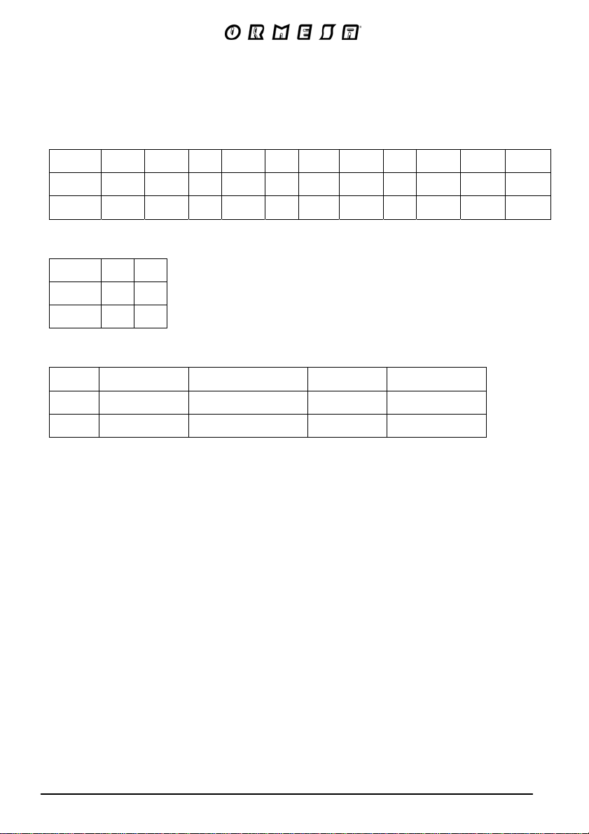
The numbers divided by the dash specify a minimum and a maximum adjustment
Measures in cm and kilos
size
1-2 41-81 52-62 37 20-30 63 40° 20-30 75 18-30 0°-35° 29-69
3-4 42-82 60-75 44 25-36 65 40° 30-40 79 30-40 0°-23° 30-70
size
1-2 36 27
3-4 44 34
size
1-2 13,5 8,5 22 35
3-4 14,5 11,5 26 45
A
(cm) B (cm)C (cm)D (cm)E (cm)
N
(cm) O (cm)
Weight of the frame Weight of the seat Total weight
(kg)
(kg)
F
(degree) (degree)
G
(cm)H (cm)I (cm)
(kg)
Max load
(kg)
L M
(cm)
49/92
Page 52
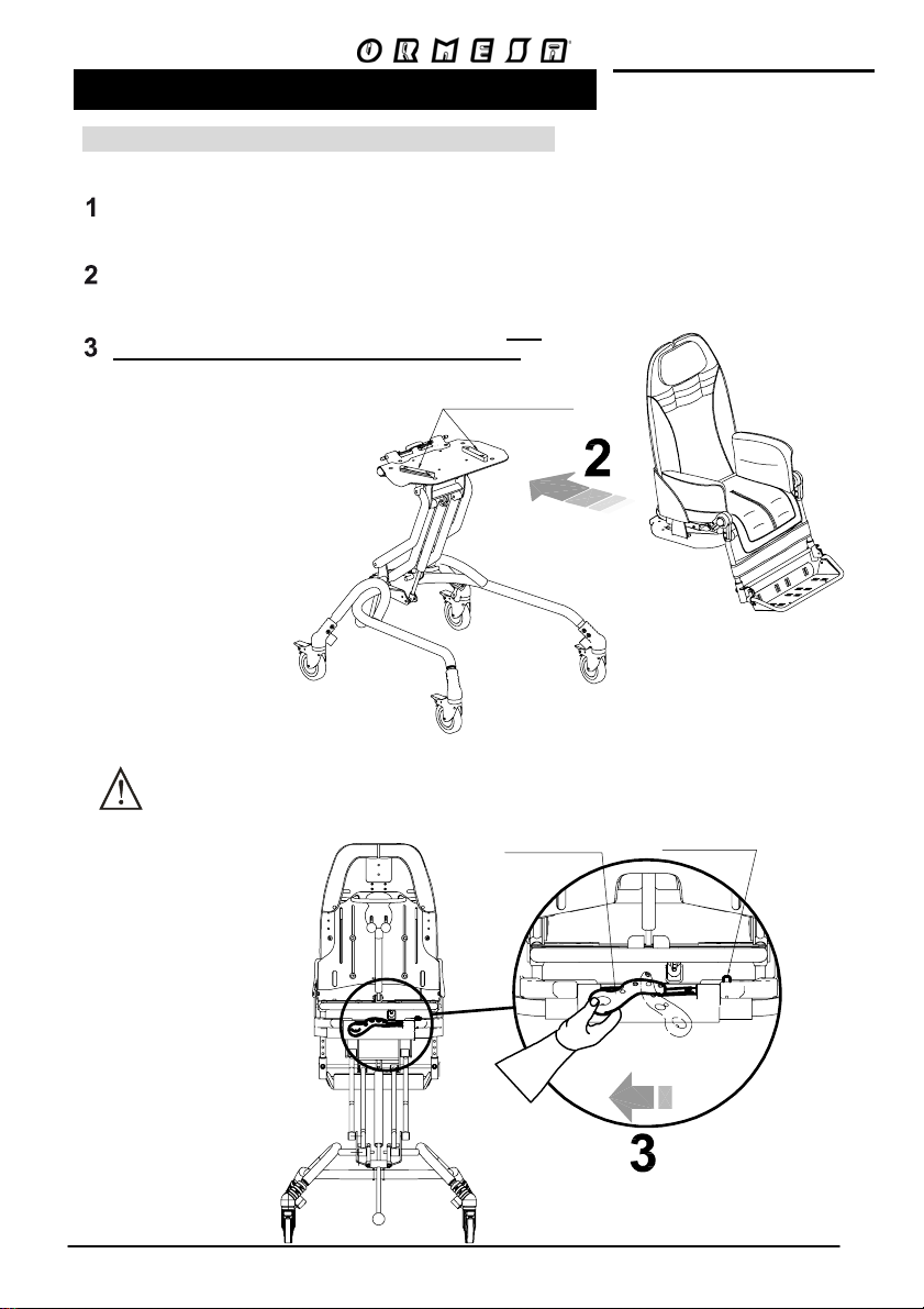
HOW TO USE Bug WITH BASE 856
HOW TO ATTACH THE SEAT TO THE FRAME
AFTER APPLYING BRAKES, PLACE THE SEAT ON THE
MOUNTING PLATE (FIG. A)
PUSH THE SEAT BACKWARDS SLIDING IT ON TO THE
MOUNTING PLATE
ENGAGE THE LOCKING LEVER (AS IN FIG. B) THE
CLICK MEANS THE SAFETY DEVICE IS LOCKED
MOUNTING PLATE
FIG. A
MAKE SURE THE SEAT IS IN THE
MOUNTING PLATE BEFORE
LOCKING IT WITH THE LEVER
FIG. B
LOCKING LEVER
50/92
LOCKS
SAFETY RED PUSH-BUTTON
UNLOCKS
Page 53
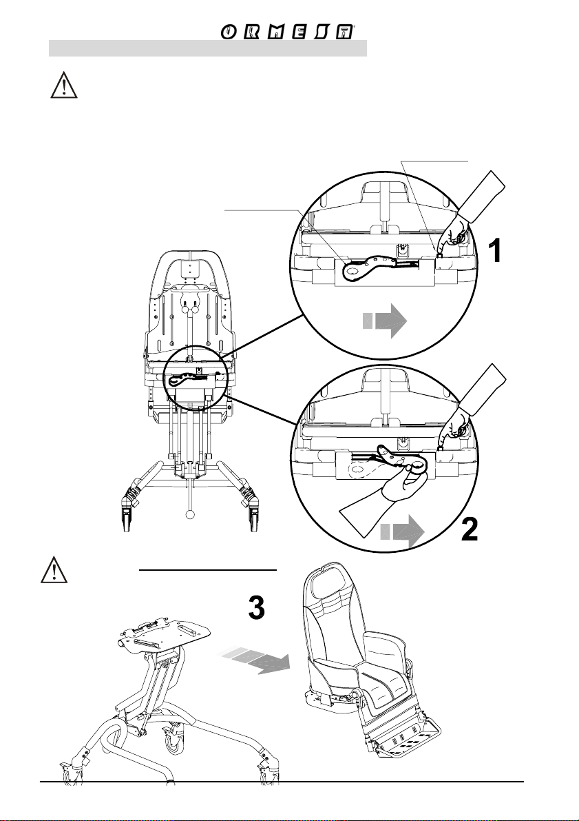
HOW TO DETACH THE SEAT FROM THE FRAME
FIRST APPLY BRAKES
1- PRESS THE SAFETY RED PUSH-BUTTON
2- AT THE SAME TIME TURN THE LOCKING LEVER FROM LEFT TO RIGHT
3- SLIDE THE SEAT FORWARD
LOCKING LEVER
VIEW FROM BEHIND
SAFETY RED
PUSH-BUTTON
THE SEAT IS NOT REVERSIBLE
WITH INDOOR BASE 856
LOCKS
LOCKS
UNLOCKS
UNLOCKS
51/9
Page 54
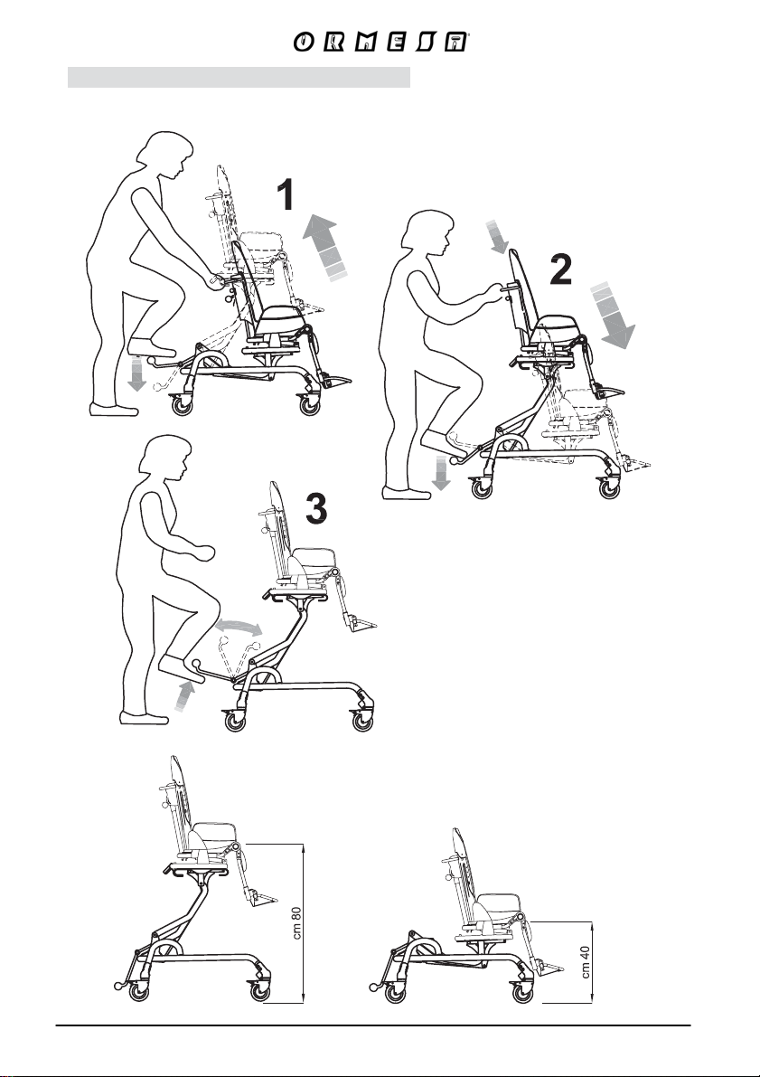
ADJUSTING THE HEIGHT OF THE SEAT
THE SEAT HEIGHT CAN BE
ALSO ADJUSTED WITH THE
CHILD SITTING ON IT
MAX. HEIGHT MIN. HEIGHT
52/9
Page 55

ACCESSORIES
53/9
Page 56
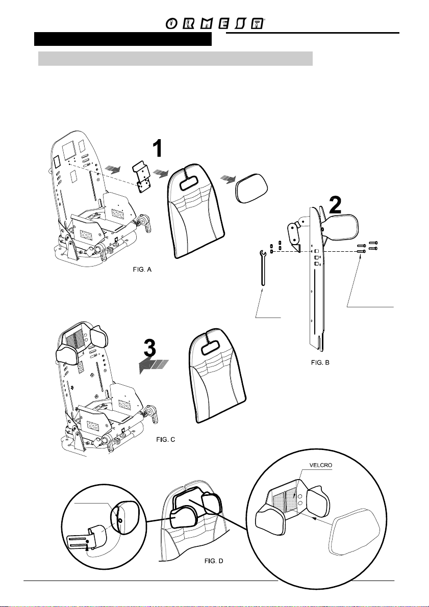
MOUNTING THE ACCESSORIES
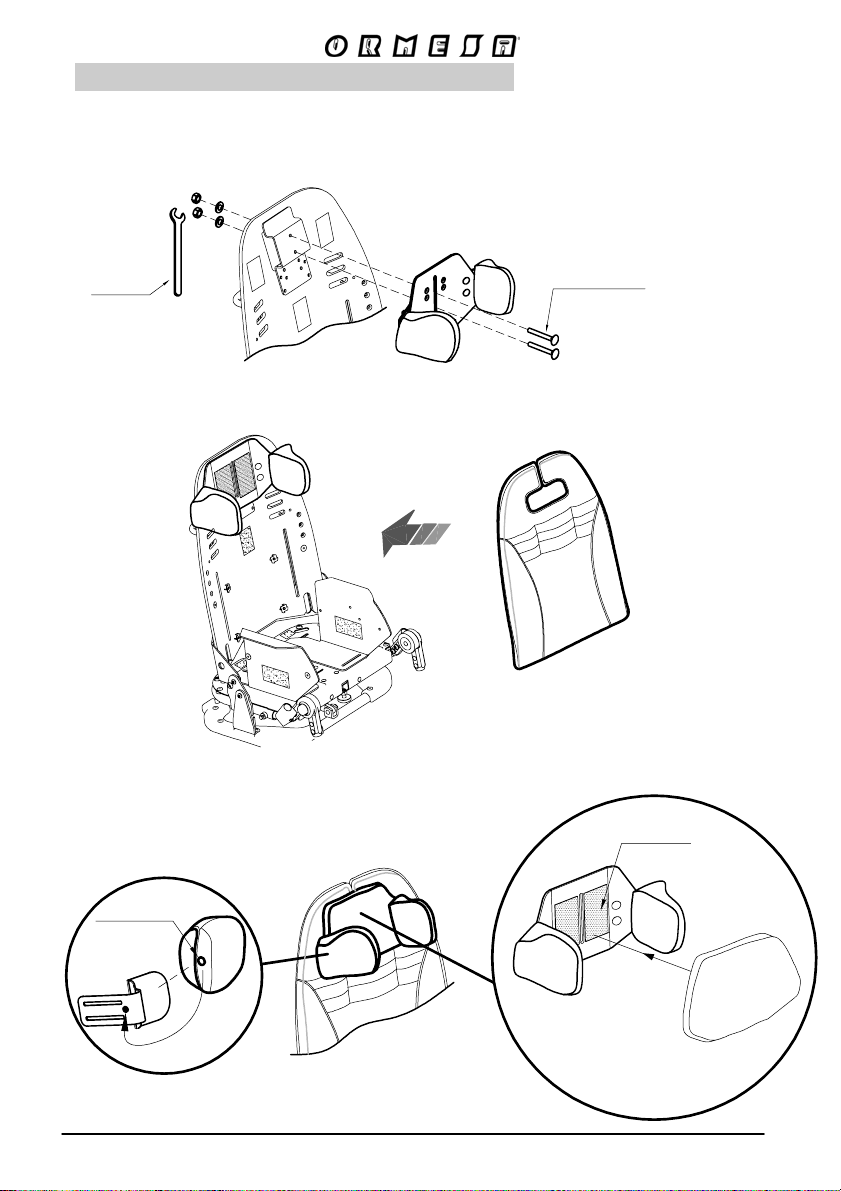
HEADREST with OCCIPITAL-PARIETAL PROTECTIONS
863
adjustable height, width, tilt and forward-backward position
1. REMOVE THE PARTS POINTED ON FIGURE A
2. FIX THE HEADREST TO THE BACKREST USING THE 4 SCREWS (FIG.B)
3. INSERT THE BACKREST CUSHION (FIG. C)
4. FIX THE CENTRAL PADDED COVER OF THE BACKREST (FIG.D)
WRENCH
4 SCREWS
TO FIX
THE HEADREST
STUD
54/9
Page 57
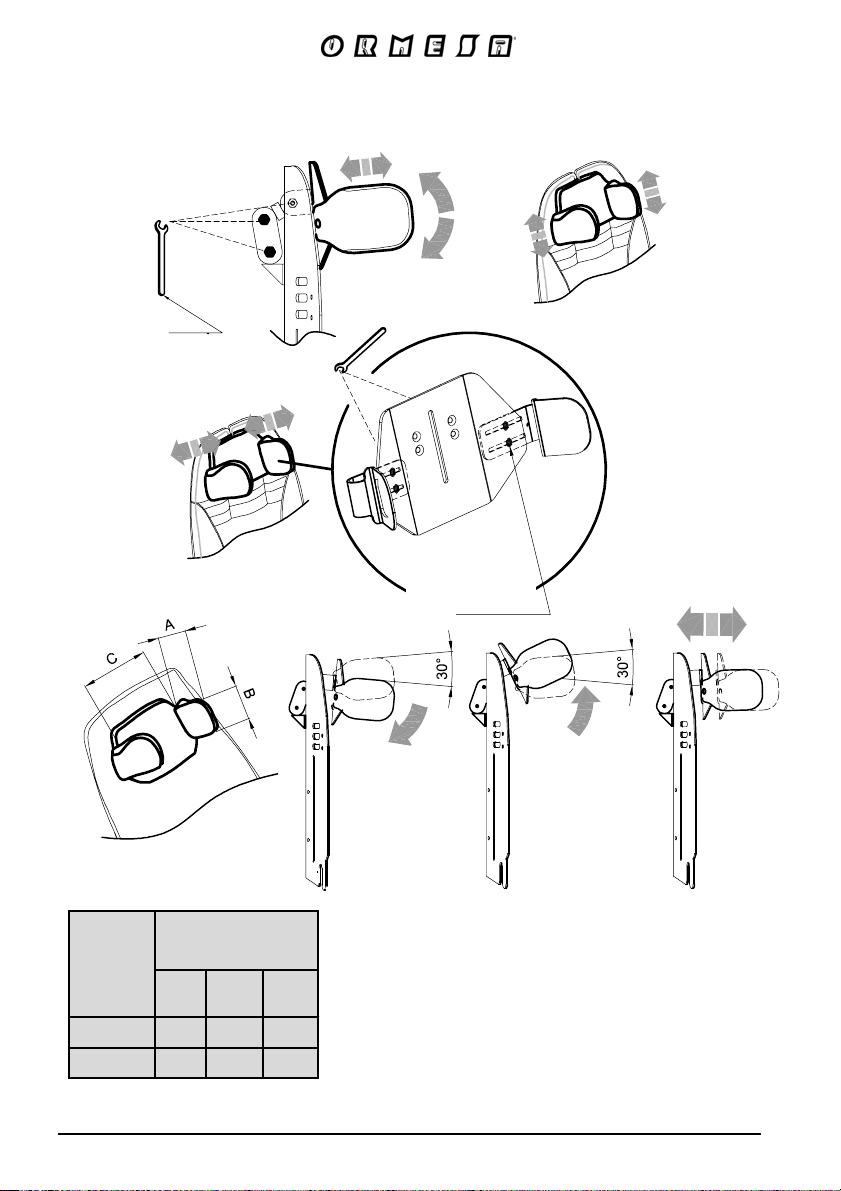
TO ADJUST THE POSITION OF THE HEADREST, SLIGHTLY LOOSEN THE
SCREWS LOCATED BEHIND THE HEADREST WITH THE PROVIDED WRENCH
SIDE VIEW
WRENCH
SCREWS
ADJUSTMENT
IN WIDTH
SIDE VIEW
HEADREST
BUG
A
(cm) B(cm) C(cm)
1-2 8 10 10-21
3-4 11 12 12-24
The numbers divided by the dash specify a minimum and a maximum adjustment
55/92
Page 58
HEADREST with PARIETAL PROTECTIONS
adjustable height and width
852
WRENCH
LOCKING ELEMENT
VELCRO
STUD
56/9
Page 59
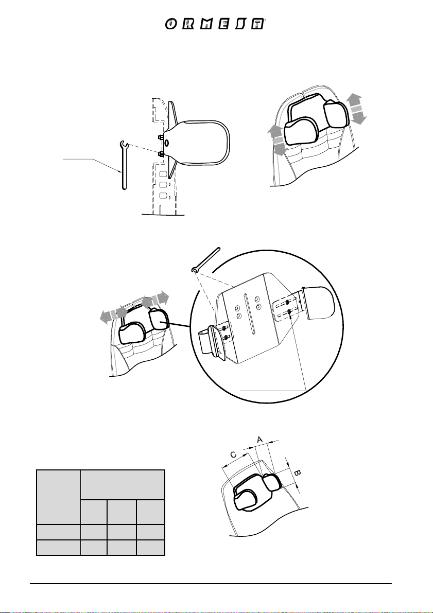
WRENCH
SIDE VIEW
SCREWS
ADJUSTMENT
IN WIDTH
HEADREST
BUG
A
(cm) B(cm) C(cm)
1-2 8 10 10-21
3-4 11 12 12-24
The numbers divided by the dash specify a minimum and a maximum adjustment
57/92
Page 60
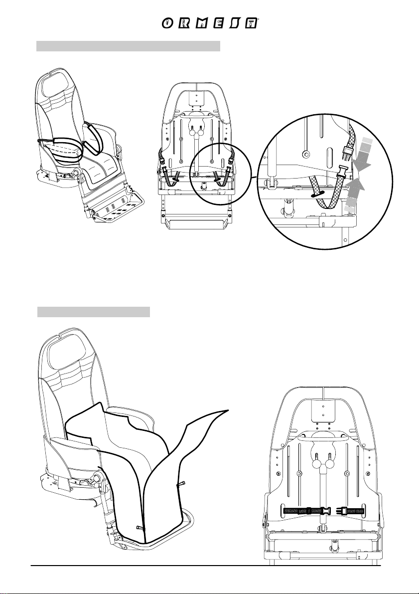
LEG DIVIDING INGUINAL STRAPS
VIEW FROM BEHIND
THERMIC COVER
817
58/92
VIEW FROM BEHIND
Page 61
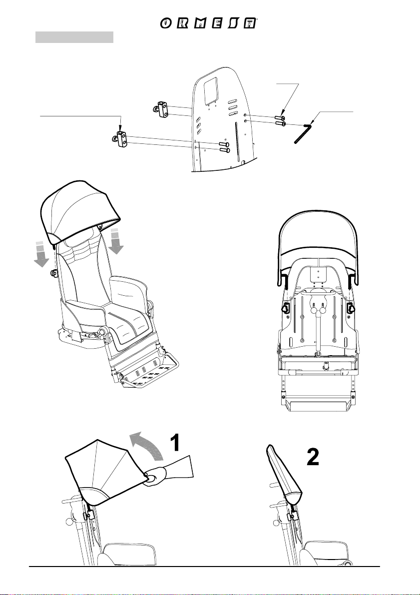
CANOPY
819
SCREW
CANOPY ATTACHMENT
WRENCH
VIEW FROM BEHIND
59/92
Page 62
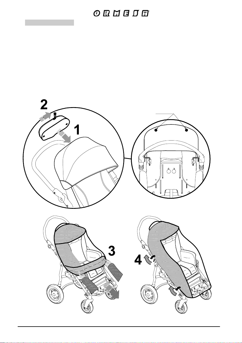
RAIN COVER
825
THE RAIN COVER CAN ONLY BE ATTACHED AFTER THE CANOPY (819) IS IN
PLACE
1- ATTACH THE RAIN COVER POUCH WITH THE TWO BUTTONS LOCATED ON THE BACK
OF THE CANOPY
2- OPEN THE ZIPPER ON THE POUCH
3- REMOVE THE RAIN COVER FROM THE POUCH AND POSITION IT SO THAT IT COVERS
THE STROLLER
4- ATTACH THE RAIN COVER TO THE FRAME USING THE STRAPS WITH BUTTONS
VIEW FROM BEHIND
THE CANOPY
STUDS
60/92
Page 63
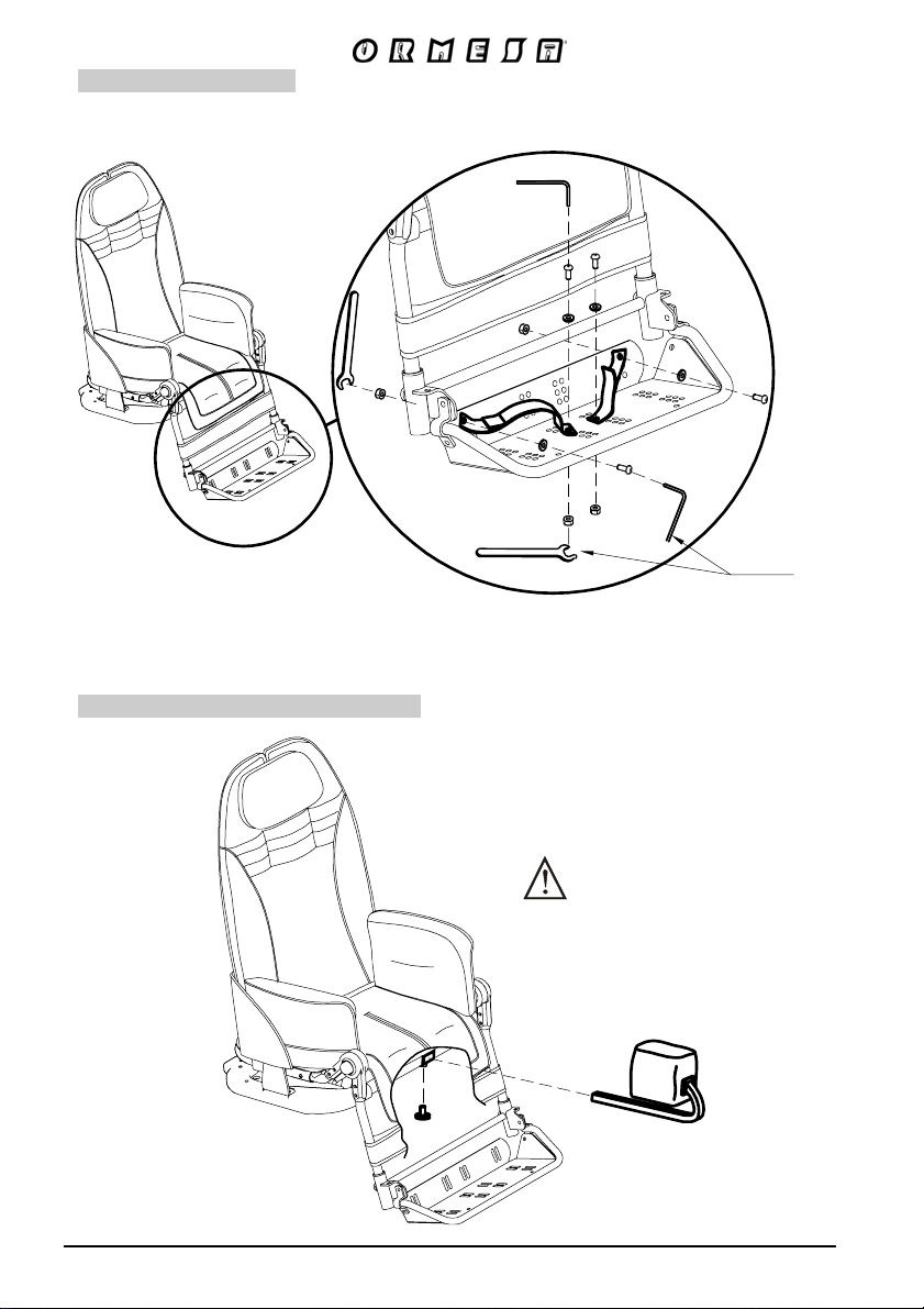
FOOT STRAPS
K
827
WRENCH
Padded ABDUCTION BLOC
834
TIGHTEN THE KNOB
61/
Page 64
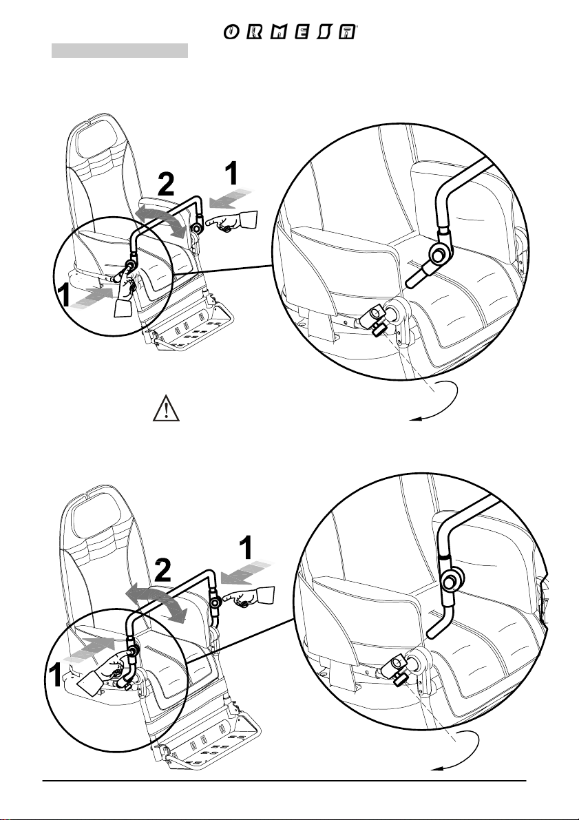
FRONT HANDLE
839
Size 1-2
TIGHTEN THE KNOB
Size 3-4
62/92
Page 65
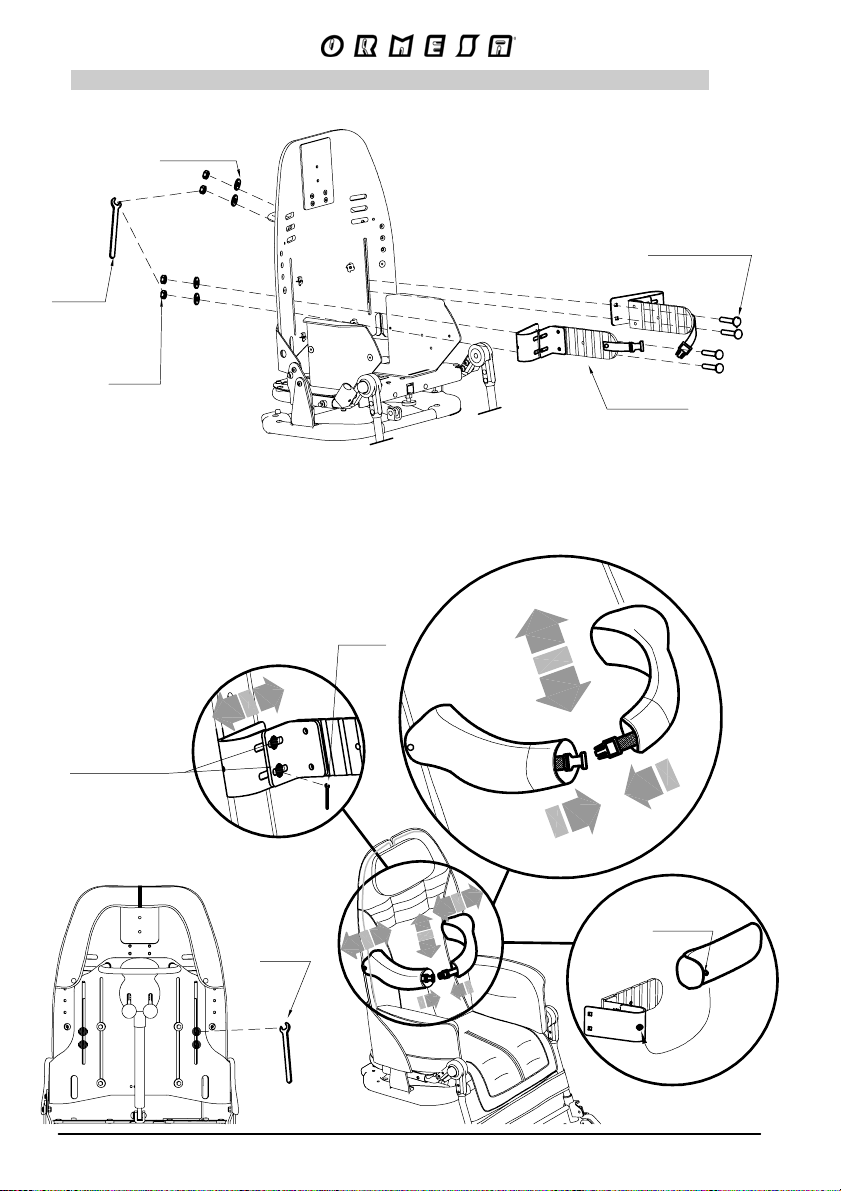
FLEXIBLE AND WRAP-AROUND SIDE SUPPORTS FOR THE TRUNK
adjustable height and width
WASHER
WRENCH
NUT
TO ADJUST THE POSITION OF THE FRONT
JOINTED BRACE, LOOSEN THE SCREWS
LOCATED BEHIND THE BACKREST WITH THE
PROVIDED WRENCH
WRENCH
LOCKING
ELEMENT
FLEXIBLE
868
SCREWS
ADJUSTMENT
IN WIDTH
VIEW FROM BEHIND
WRENCH
STUD
63/92
Page 66
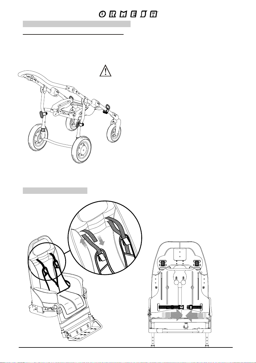
891 TIEDOWN HOOKS (4 RINGS)
V
only available for the 4-wheel 869 base
THE BUG 4-WHEEL STROLLER (seat unit + 869 base) conforms to the ISO 7176-19 and
ANSI RESNA WC/19 standard, which defines the safety requirements for transport, facing
in the direction of travel, on moving vehicles (private cars, buses, etc.)
VIEW FROM BEHIND
891
FOR THE ASSEMBLY OF THE 891 ACCESSORY AND
ANCHORING THE STROLLER TO THE VEHICLE,
CAREFULLY READ THE INSTRUCTIONS AND NOTICES
ON PAGES 13, 14, 15, 16 AND 17 OF THIS MANUAL
EST HARNESS
853
VIEW FROM BEHIND
64/92
Page 67
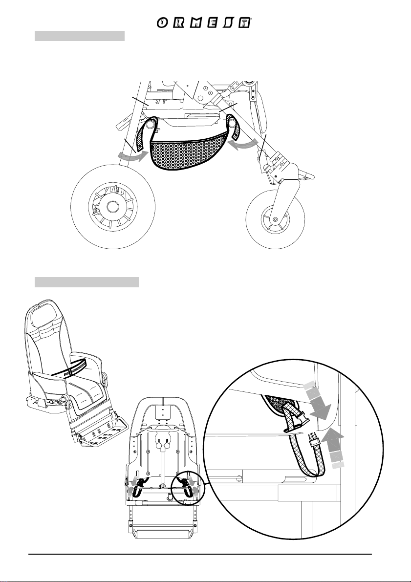
NET BASKET
Only available for OUTDOOR BASES
858
869 and 901
45° SEAT BELT
894
VIEW FROM BEHIND
65/92
Page 68
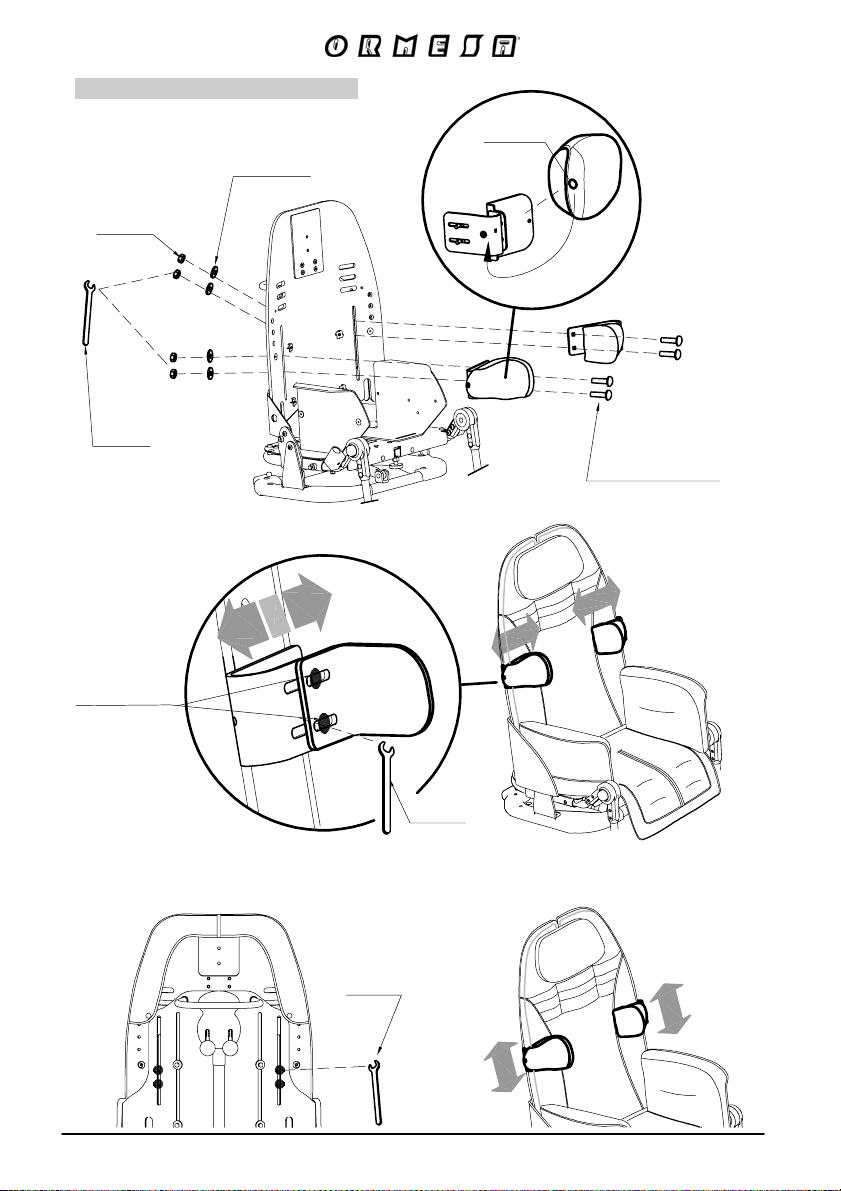
Padded SIDE SUPPORTS
WASHER
NUT
WRENCH
838
STUD
LOCKING ELEMENT
SCREWS
ADJUSTMENT
IN WIDTH
VIEW FROM BEHIND
WRENCH
WRENCH
66/92
Page 69
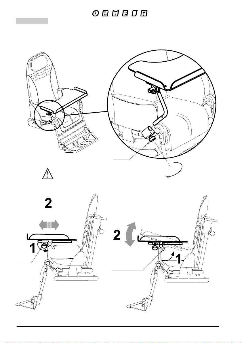
TRAY
824
TIGHTEN THE KNOB AND
THE LOCKING LEVER
KNOB
KNOB
LOCKING LEVER
67/92
Page 70
5-POINT VEST HARNESS
903
VIEW FROM BEHIND
68/92
Page 71
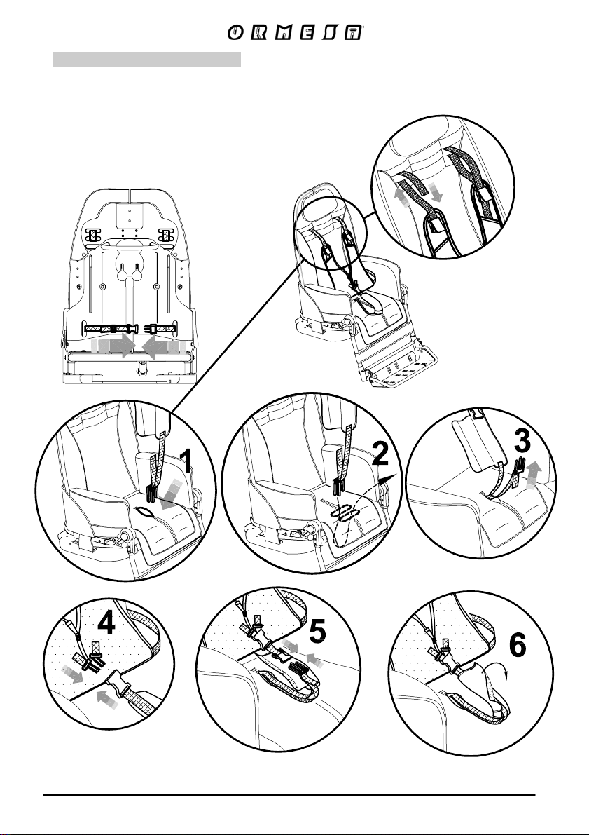
5-POINT HARNESS
906
1 FIXING THE STRAP ON THE BOTTOM OF THE SEAT
2 FIXING THE STRAPS ON THE 3 FIXING THE BACK BUCKLES
UPPER PART OF THE BACKREST
VIEW FROM BEHIND
69/92
Page 72
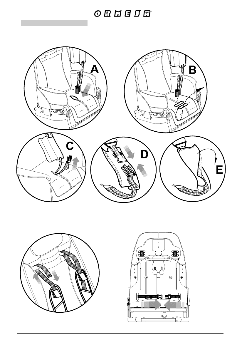
FIXING THE FRONT BUCKLES
4
ASSEMBLED HARNESS
5
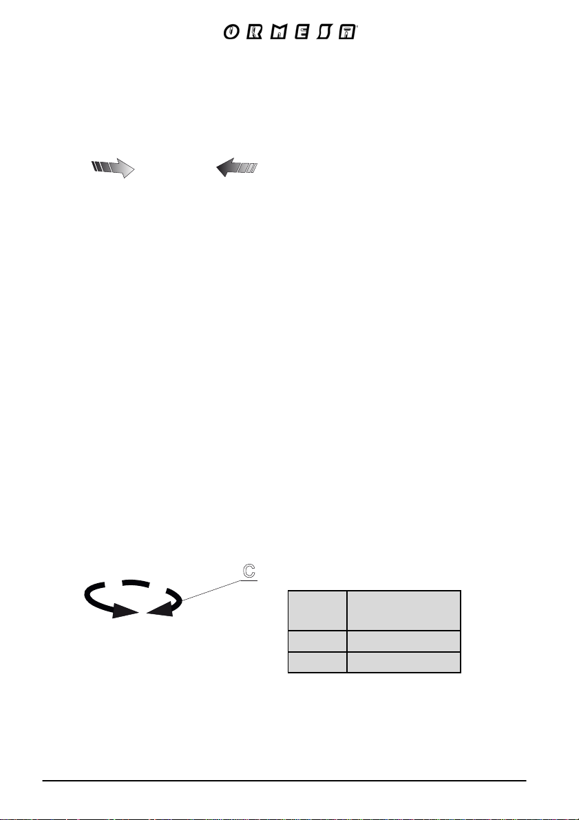
c
BUG
sizes
1-2 57-84
3-4 80-108
The numbers divided by the dash specify
a minimum and a maximum adjustment
70/
Circumference
Min. max. (cm)
Page 73
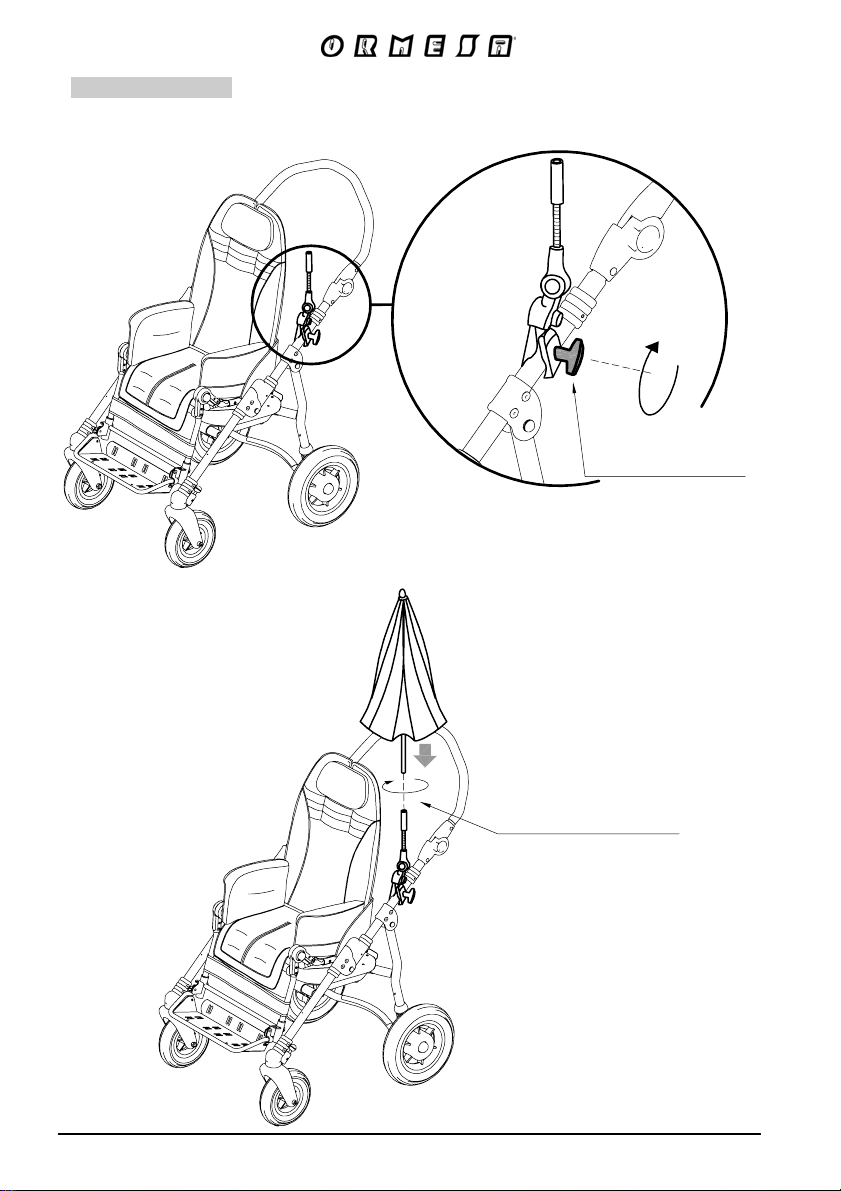
PARASOL
854
A - PLACEMENT and MOUNTING
Tighten the knob
to secure it
71/92
Tighten the parasol
on its fixing part
Page 74
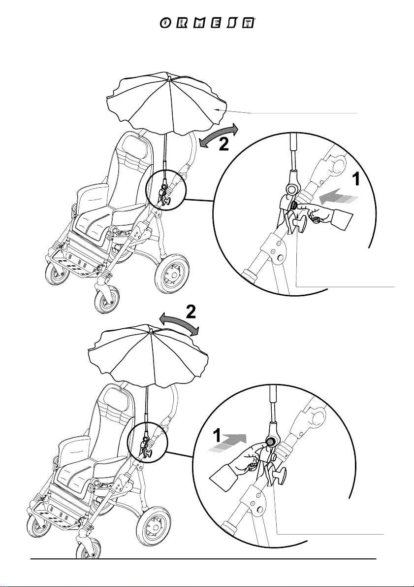
B – ADJUSTMENT WITH BUTTONS
The opening and closing
of the “parasol” are like
a conventional parasol
button for adjusting
in backward-forward
position
72/92
button for adjusting
from left to right
Page 75
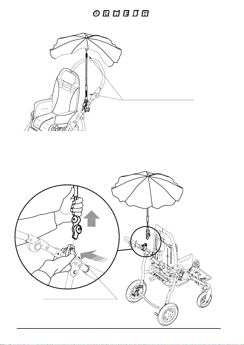
C – ADJUSTMENT WITH THE FLEXIBLE PARTS
Acting on the flexible parts
of the bar you can adjust
the parasol in all directions
D
– REMOVING THE PARASOL
To remove it PRESS the button and SIMULTANEOUSLY PULL the Parasol
To reinsert the parasol it is not necessary to press the button
Button to remove the parasol
NOTE : before folding the pushchair remove the parasol
73/92
VIEW OF THE
PUSHCHAIR
FROM BEHIND
Page 76
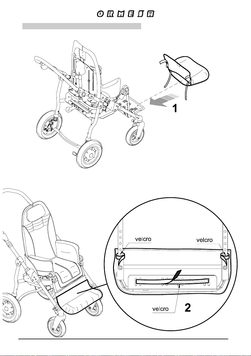
PADDED COVERING for FOOTPLATE
892
74/92
VIEW FROM BEHIND
OF THE FOOTPLATE
Page 77
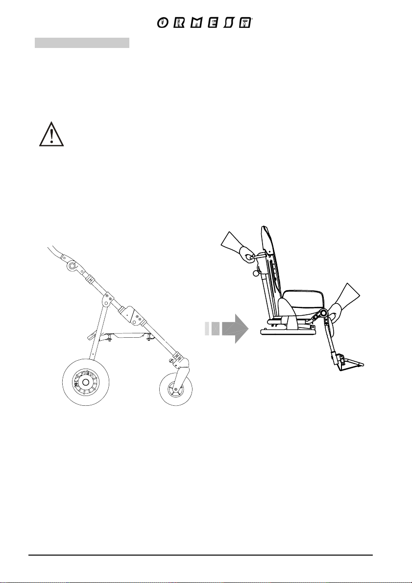
HAND BRAKE
905
A - TAKE THE SEAT OUT OF THE FRAME
BEWARE !
such as the manufacturer or the dealer who sold the product or a specialized
mechanical company
The hand brake must be installed by qualified personnel,
75/92
Page 78
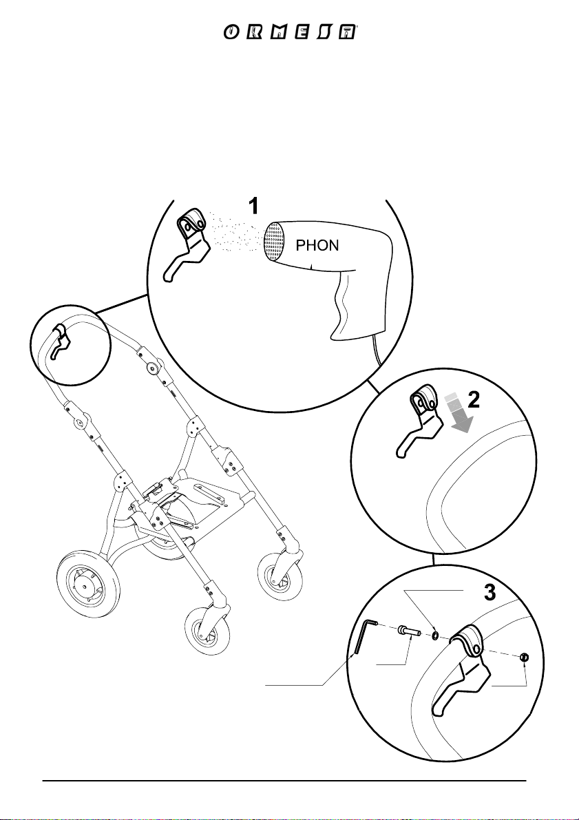
B - FIXING THE LEVER OF THE HAND BRAKE
1-GET THE PLASTIC PART OF THE BRAKE LEVER WARM, BY USING A DRYER
2-PUT THE BRAKE LEVER ON THE PUSH HANDLE
3-FIX AND TIGHTEN THE SCREW
WRENCH
76/92
WASHER
SCREW
NUT
Page 79
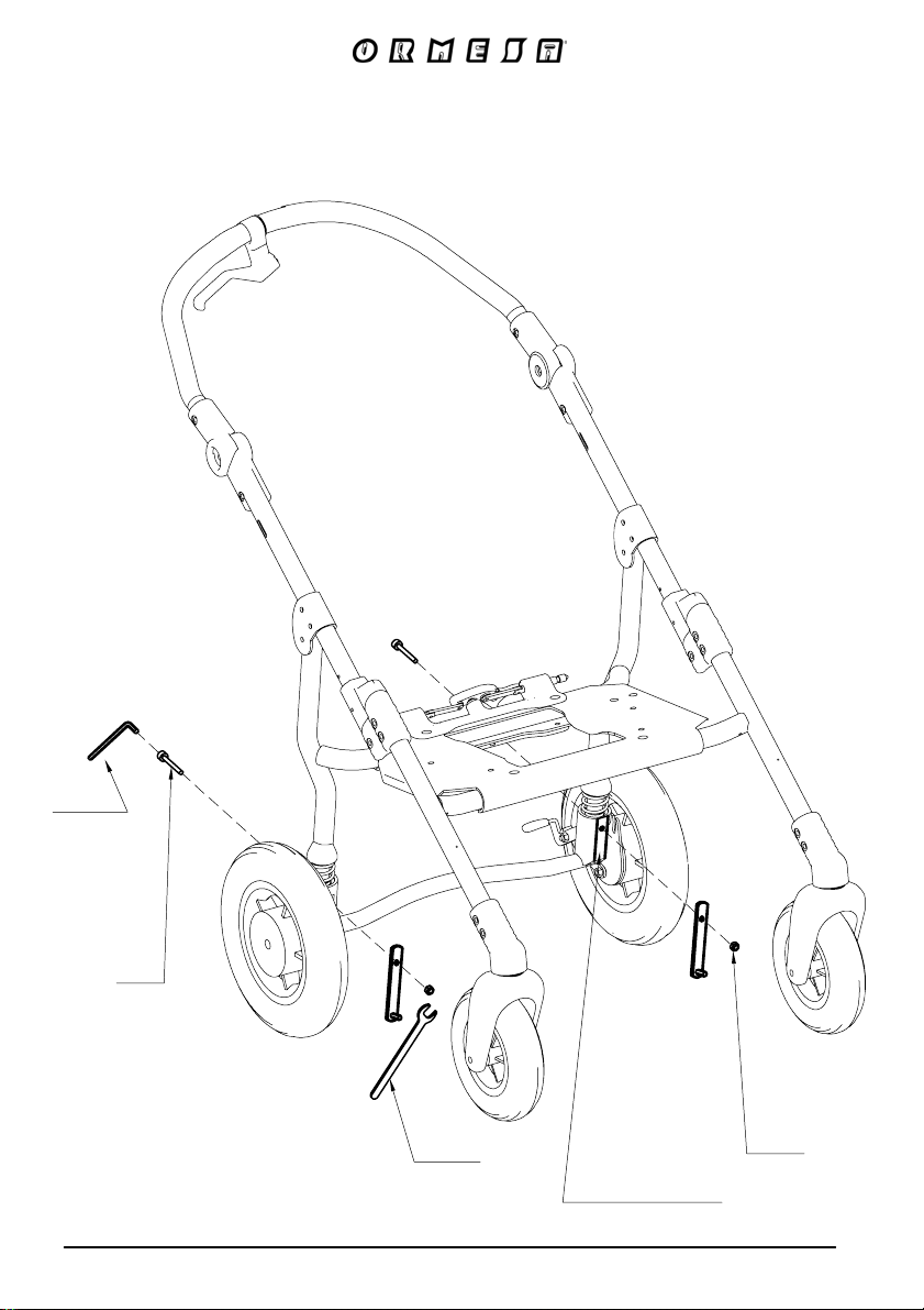
C - ASSEMBLING THE TWO PLATES
WRENCH
SCREW
WRENCH
77/92
The plates
must be positioned
in its own channel
NUT
Page 80
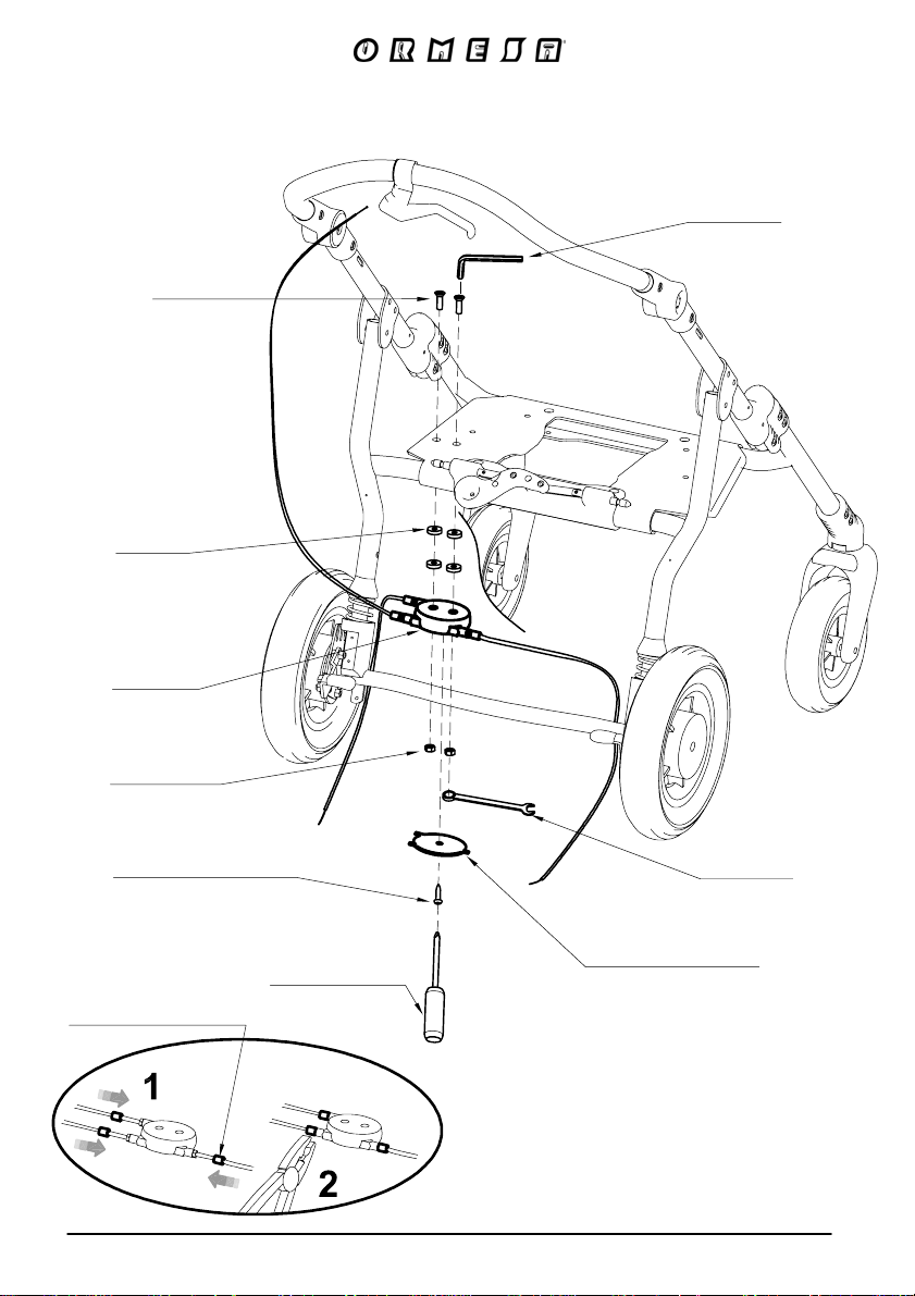
D - FIXING THE DOUBLER OF THE BRAKE
SCREW
WASHER
DOUBLER
WRENCH
NUT
TAPPING SCREW FOR
THE COVER OF
THE DUPLICATOR
SHEATH COVER
WRENCH
DOUBLER COVER
SCREW DRIVE
AFTER POSITIONING THE DOUBLER COVER:
1-INSERT THE THREE SHEATH COVERS
2-PRESS THEM WITH PINCERS
78/92
Page 81
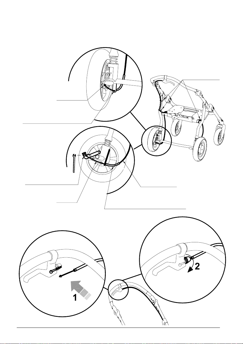
E
- FIXING THE CABLES
CABLE LOCK
HOLE TO INSERT THE CABLE
RUBBER RINGS
CABLE TERMINAL LOCK
CABLE
BLACK SHEATH
TRANSPARENT EXTERNAL SHEATH
79/92
Page 82
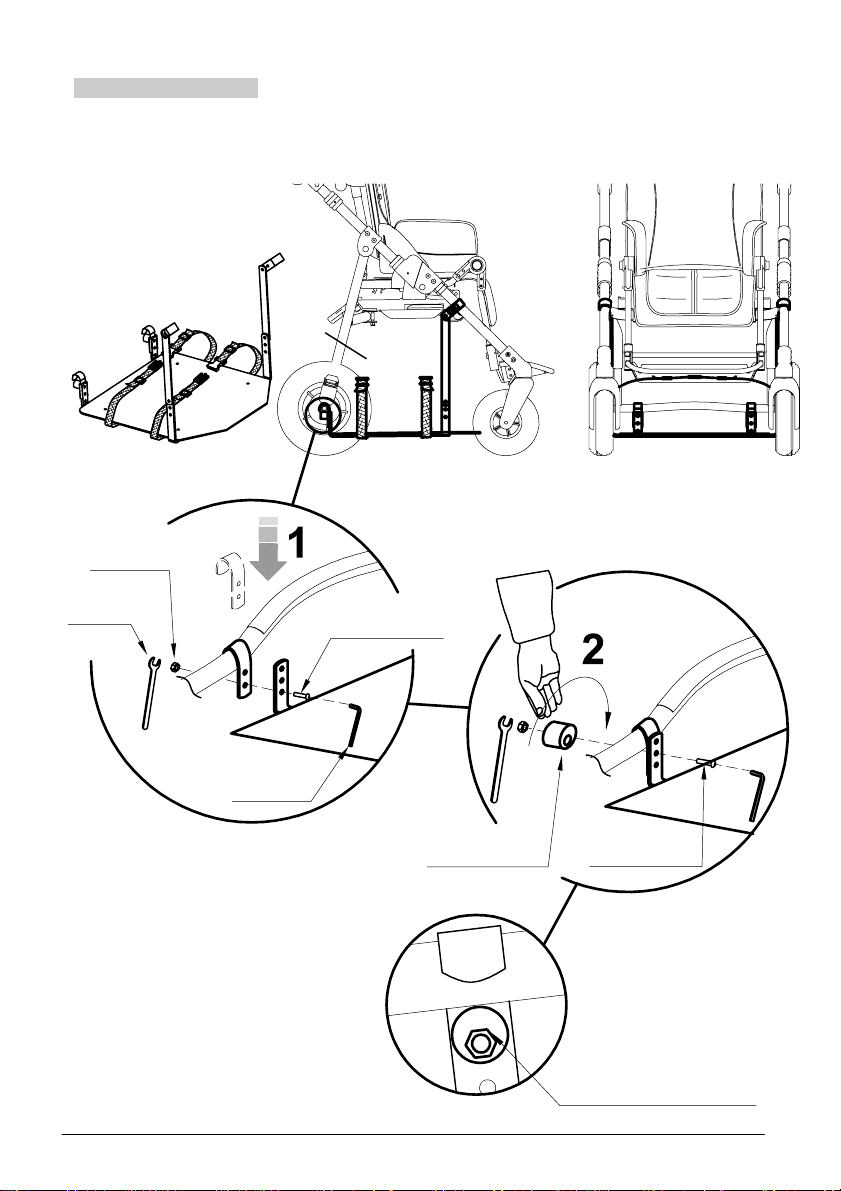
VENT TRAY
911
Available only for 869 and 901 external bases
NUT M6
WRENCH
WRENCH
SCREW M6X16
ADJUSTABLE
BUSHING
80/92
SCREW M6X25
HOW TO FIX THE
ADJUSTABLE BUSHING
Page 83
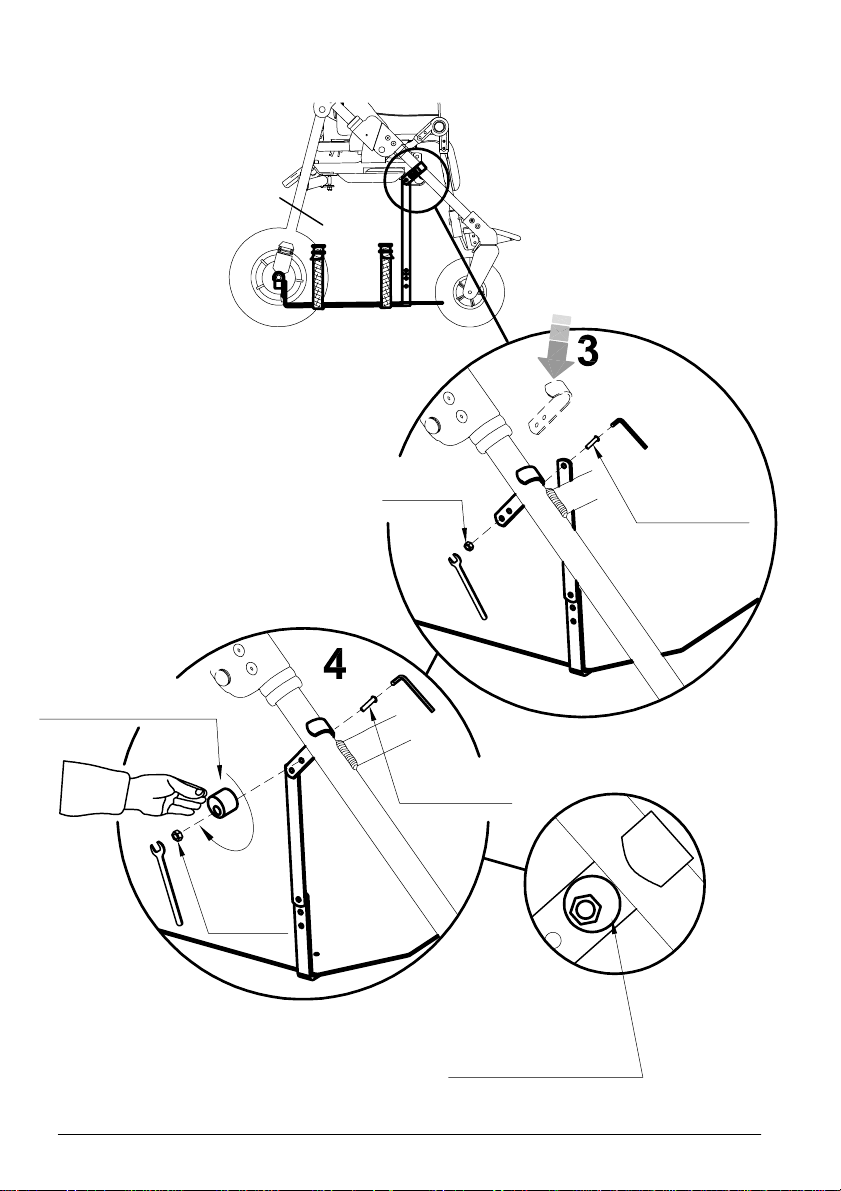
ADJUSTABLE
BUSHING
NUT M6
SCREW M6X25
SCREW M6X25
HOW TO FIX THE
ADJUSTABLE BUSHING
81/92
Page 84
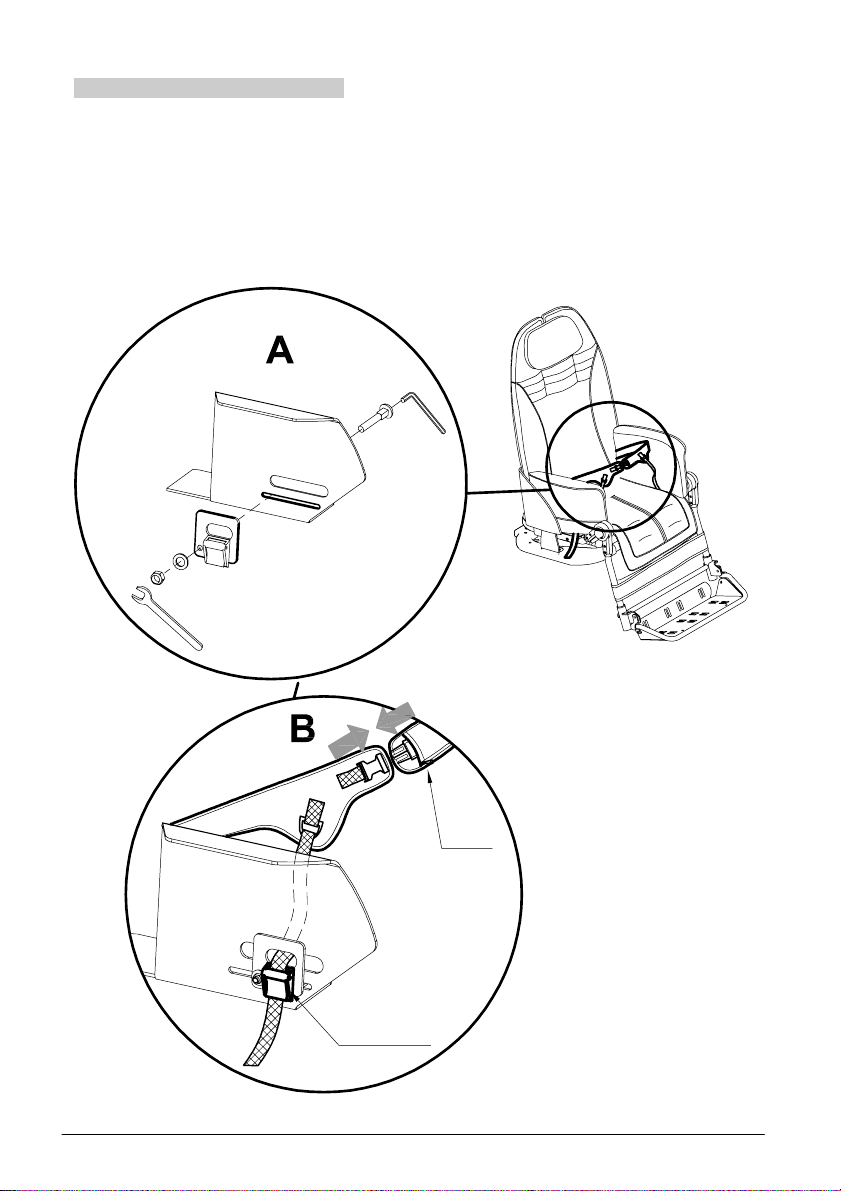
4-POINT
SEAT BELT
920
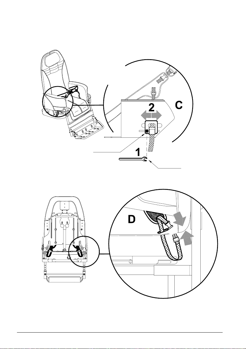
BEFORE FIXING THE 4-POINT SEAT BELT REMOVE THE SIDE UPHOLSTERIES
(SEE PAGE 88)
zip
buckle
82/92
Page 85
REAR VIEW
ADJUSTMENT IN DEPTH
nut M5
wrench
83/92
Page 86
SIBLING REAR FOOTBOARD
Available only for 869 and 901 external bases
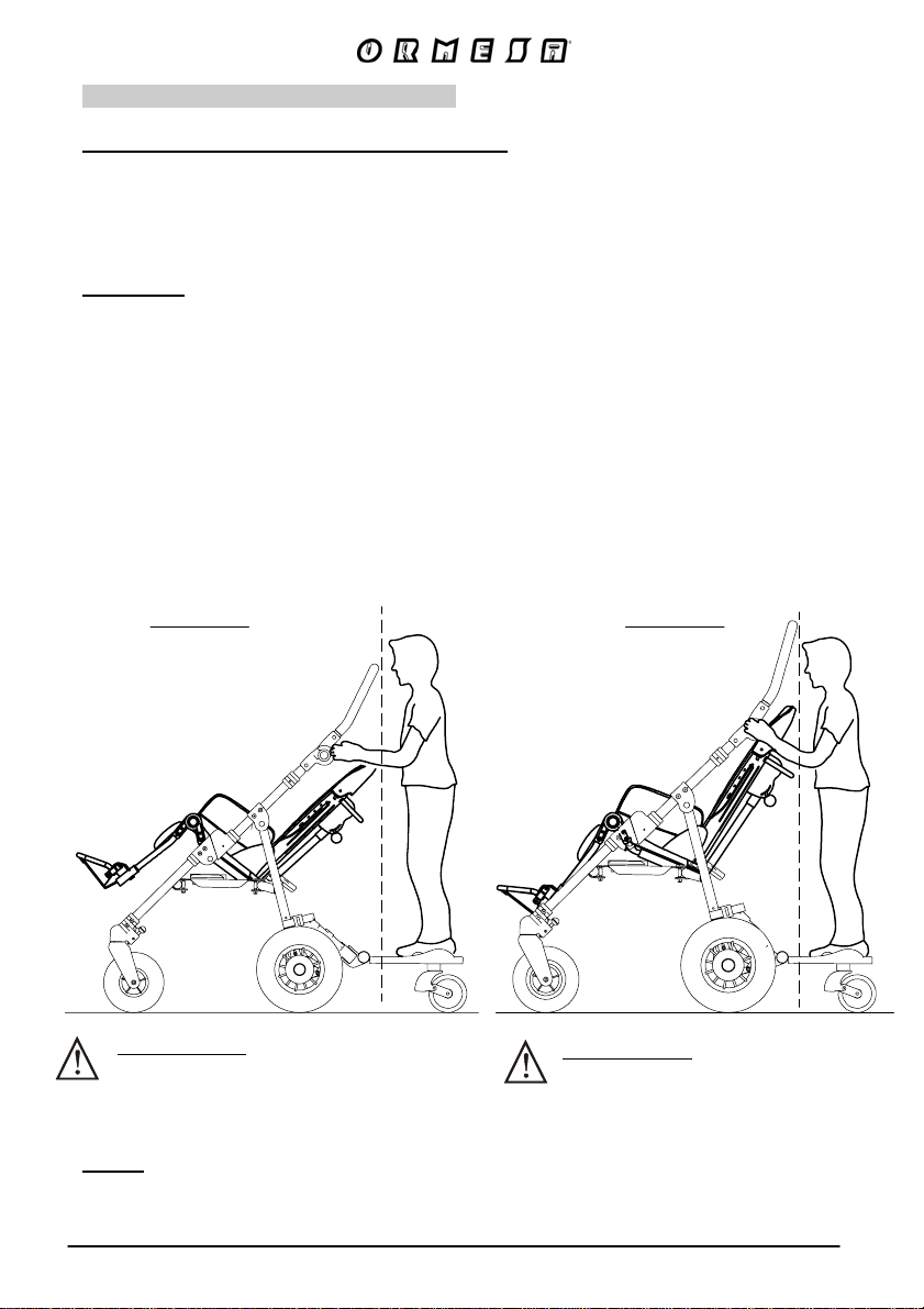
The 921sibling rear footboard must be fixed on the back thanks to the plastic straps. It
has a telescopic arm to adjust the footboard in depth, screws to adjust the tilt and two
pivoting wheels.
the board is suitable for children from 2 to 5 years old, weighing less than 20 kg.
WARNING:
- Never leave the child unattended
- Make sure all the blocking devices are correctly installed before use.
- Do not use the board if your child cannot walk independently and without help.
- The footboard can be tipped up (see the Manufacturer Manual). However remove
the board before folding the pushchair.
- Children must only be transported on the footboard in a standing position.
- Allow your child to alight from the boar
stairs, steep paths, tight corners, as well as when maneuvering backwards.
- The use of the board is only admissible if
pushchair.
- This products is not suitable for the while running or skating.
921
d, before reaching pavement edges,
there is a second child in the
SIZE 1-2
COMPLETELY
RECLINED BACKREST
YES
Notes:
- For more information on the adjustment, closure, maintainance of the board,
OR COMPLETELY
TILTED SEAT
ATTENTION!
THE SIBLING REAR FOOTBOARD
LIMITS THE INTERMEDIATE
COMBINATIONS
refer to the user manual of the manufacturer, supplied with the footboard .
YES
SIZE 3-4
COMPLETELY
TILTED SEAT
ATTENTION!
THE SIBLING REAR FOOTBOARD
LIMITS THE BACKREST RECLINE
AND THE RECLINE/TILT
COMBINATIONS
84/92
Page 87
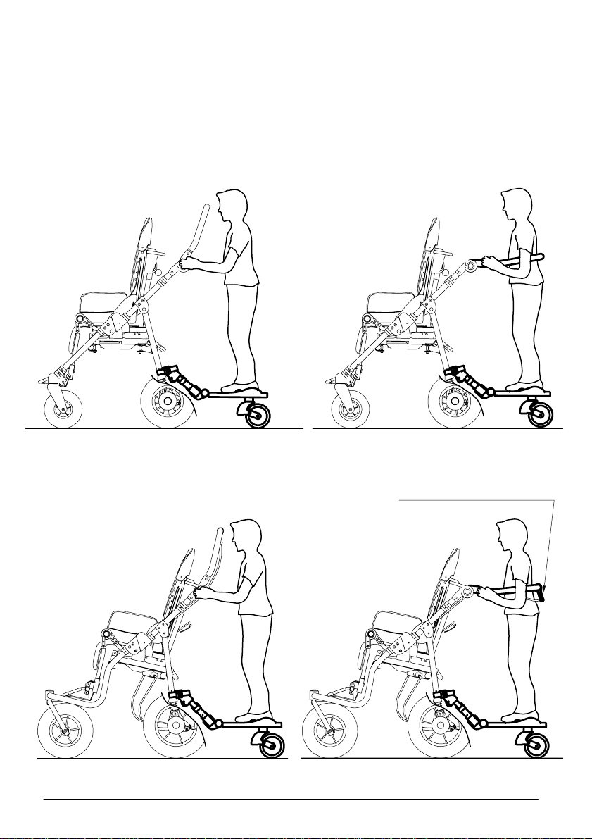
A
- PLACEMENT OF THE CHILD ON THE BOARD
It is recommended to adjust the push handle and the telescopic arms in order to
guarantee the comfort both of the child on the rear footboard and the driver. In effect,
adjusting the telescopic arms to their maximum extension, could reduce the available
space inside the push handle exces
a) BUG seat with 4 wheel base 869
sively and/or the footboard could hinder the driver.
b) BUG seat with 3 wheel base 901
Turn the brake lever
to make the child's position
more comfortable
85/92
Page 88
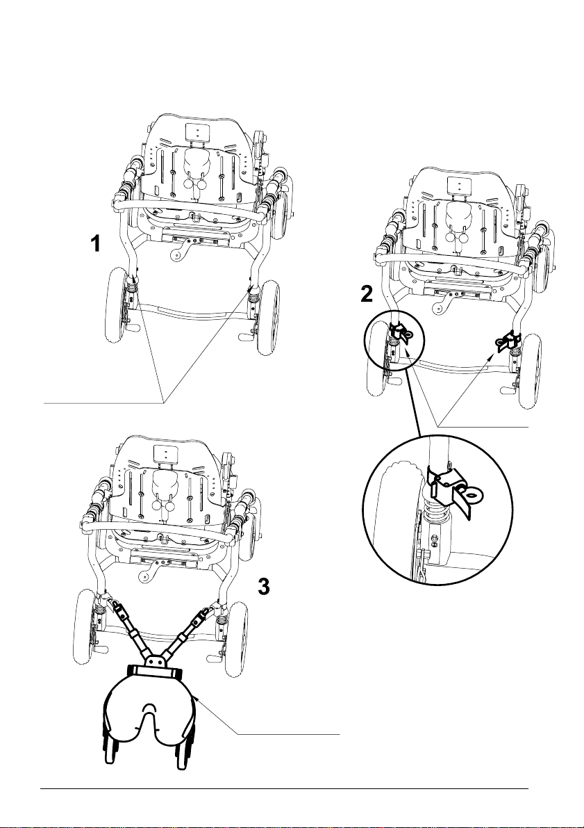
B
- MOUNTING
where to place
the straps
to position the board
VIEW FROM BEHIND
TO MOUNT THE STRAPS
FOLLOW THE INSTRUCTIONS
OF THE MANUFACTURER OF
THE BOARD
Mounted straps
TO ATTACH THE STRAPS
FOLLOW THE INSTRUCTIONS
OF THE MANUFACTURER OF
THE BOARD
Board attached
86/92
Page 89
BOTTLE HOLDER
922
87/92
Page 90
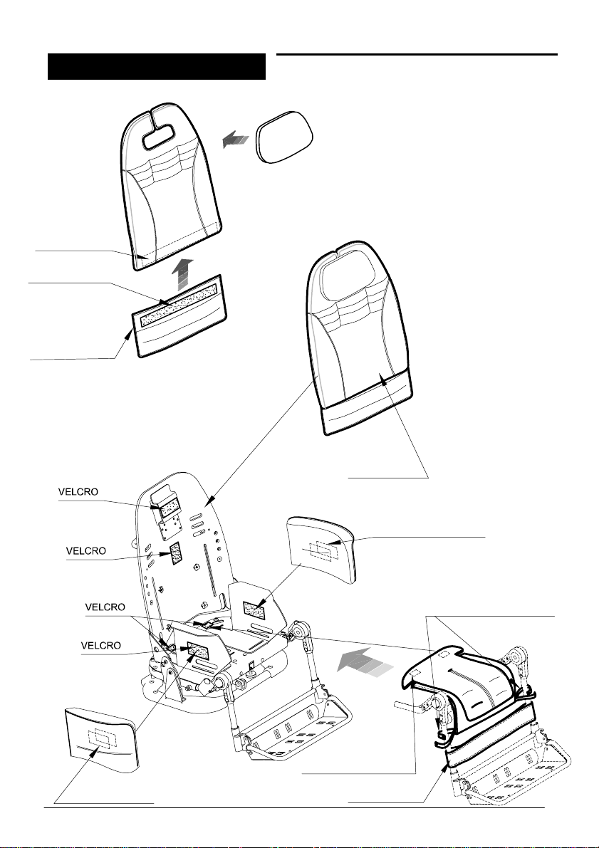
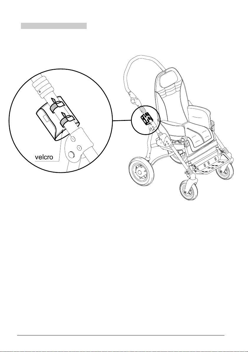
ATTACHING THE CUSHION
BUTTONHOLE
VELCRO
ON THE BACK
OF THE BACKREST
HOOK VELCRO
EXTENSION
OF THE
BACKREST
CUSHION
EXTENDED
BACKREST
CUSHION
INSIDE VELCRO
INSIDE VELCRO
STRAPS WITH BUTTON
TO FIX THE CUSHION
UNDERNEATH VELCRO
LEGREST BAND
88/92
Page 91
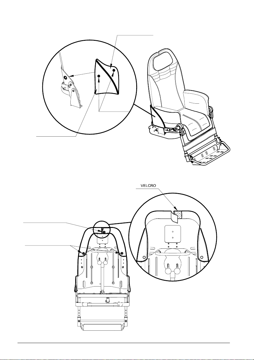
RIGID PART
SOFT PART
INSIDE BUTTON
STUD
INSIDE VELCRO
BUTTONS TO FIX THE
CUSHION IN THE BACK
OF THE BACKREST
VIEW FROM BEHIND
89/92
Page 92
MAINTENANCE, CLEANING AND DISINFECTION
REGULAR (OR PREVENTIVE) MAINTENANCE
ORDINARY MAINTENANCE OF THE AID AND ITS ACCESSORIES MUST BE PERFORMED
MONTHLY. REGULAR MAINTENANCE IS REQUIRED TO KEEP THE PRODUCT WORKING
PROPERLY AND SAFELY AND IT IS ESSENTIAL FOR KEEPING THE CE MARK.
THE MANUFACTURER IS NOT LIABLE FOR THE PERFORMANCE OF THE PRODUCT
UNLESS REGULAR MAINTENANCE IS PERFORMED (ATTACHMENT I, DIRECTIVE
2007/47/EC). THE MANUFACTURER ALSO RECOMMENDS THE CARE GIVER TO CONTACT
A SERVICE CENTER SPECIALIZED IN THE MAINTENANCE OF MECHANICAL AIDS FOR
DISABLES IN ORDER TO PERFORMS A COMPLETE REVIEW OF THE PRODUCT'S
OPERATION AND SAFETY WITH THE FOLLOWING FREQUENCIES:
1) at three months from purchase;
2) at six months from purchase;
3) once a year for subsequent years after that of purchase.
Clean and disinfect the device and its accessories regularly, following the
instructions provided below.
CLEANING AND DISINFECTING THE FRAME
Clean and disinfect the painted and chromium plated parts of the seat and base with a soft cloth
dipped in a household detergent and disinfectant, such as alcohol diluted in water.
CLEANING AND DISINFECTING THE UPHOLSTERIES
Clean Canopy 819, Rain Cover 825 and the Padded Abduction Block 834 with a damp sponge
and water. Carefully follow the instructions below for washing the upholstery and cushions of the
seat unit with neutral household soap:
- detach the five parts of the cushion from the backrest and seat bottom;
- slip off the covers on the accessories Headrest 863, Headrest 852, Side Supports 868, Side
Supports 838;
- wash upholstered accessories, covers and cushions respecting the following symbols:
Machine wash with
neutral soap (Max.
temperature 30°C)
Do not spin dry
Do not bleach
Dry clean with
perchloroethylene
Do not iron
Do not tumble dry
- Once dried, reattach the cushions to the frame using the buttons.
CLEANING THE TRAY
Clean tray 824 with a sponge wet with detergent or household disinfectant. After rinsing, dry well
with a soft cloth.
90/92
Page 93
LUBRICATION
The product does not need any special lubrication. DO NOT GREASE THE REAR WHEELS
because this could make the BRAKES INEFFICIENT.
MAINTAINING THE WHEELS
At least once a month, clean the wheels of residues (threads, hair, etc.) that can build up on
rotating parts. Maintain a constant pressure in the tires of 2.5 atm (only for alternative pneumatic
wheels, base 869 and 901 for outdoor use)
If you notice any INEFFICIENCY, even partial, of the BRAKES, immediately contact
a specialized service center or the reseller where you purchased the product ,
will determine whether they need to be repaired or replace d
situations that could cause accidents.
to avoid dangerous
who
Do NOT perform maintenance or replace parts or accessories when the user is
sitting on the device
Intensify all checks in marine environments, clean more often, anoint the parts
exposed to salt corrosion (such as chrome, bolts and screws)
EXTRAORDINARY (OR CORRECTIVE) MAINTENANCE
EXTRAORDINARY MAINTENANCE MEANS ANYTHING DONE TO THE PRODUCT TH AT IS
NOT MENTIONED ABOVE.
WE RECOMMEND THAT THE USER, RETAILER AND HEALTH FACILITIES ENTRUS T ALL
EXTRAORDINARY OR CORRECTIVE MAINTENANCE TO THE M ANUFACTURER OR OTHER
FACTORY-AUTHORIZED SERVICE CENTRE.
ANY OTHER SOLUTION WILL RESULT IN THE USER AND THE THIRD-PARTY MAINTAINER
FULLY RESPONSIBLE FOR THE RESULTS OF THEIR WORK AND THE MANUFACTURER
WILL ONLY BE LIABLE FOR ORIGINAL DEFECTS OF MATERIALS OR WORKMANSHIP.
If the product is to be disposed of, it must be done according to the law in the
country of destination
CUSTOMER SERVICE AND SPARE PARTS
Only contact the retailer where you purchased the product for service and replacement with
original spare parts.
91/92
Page 94

CONDITIONS FOR DURABILITY, REUSE AND
REASSIGNMENT TO A NEW USER
Granted that Ormesa products should be selected, evaluated and ordered for
the needs of an individual user, reuse is however possible with the respect the
following conditions.
Based on the experience of other similar sold models, on technological progress, on
the guarantees of the Quality Management System certificated in 1998 according to
ISO 9001, there is adequate confidence that the average lifespan of the BUG is
about 5 years, on condition that it is used according to the directions given in
the user manual.
Only when the conditions for storage and transport of chapter HOW TO STORE AND
TRANSPORT THE MEDICAL DEVICE” are followed, the periods in which the
product is stored at the dealer should not be considered in that time period
Factors unrelated to the product such as the development of the user, its
diseases, the use and the surrounding environment can make significantly
lower the duration of life of the product; on the contrary, if the indications on
the use and maintenance are properly observed, the reliability of the product
can extend well beyond the lifetime average above.
Prior to recycling or reassignment an already used Ormesa product, it is
required that:
1. a doctor or therapist verifies that the aid is appropriate and adequate
to meet the dimensional, functional and postural needs of the new
user, and if all its components are suitable / appropriate for him. You
should also consider that the
responsibility for safety requirements for the product remain only if
the original product still has not changed and only original
accessories or spare parts have been applied
2. qualified technical personnel of a company specialized in the
maintenance of technical aids for disabled people performs a detailed
technical inspection to verify its condition and wear, the absence of
any damage and failure of all components / adjustments, the presence
of the user’s manual, of the label with the date and serial number. A
copy of the manual and maintenance may be always requested to the
retailer that supplied the product or directly to Ormesa
3. The product has been thoroughly cleaned and disinfected following
the directions given in the “MAINTENANCE, CLEANING AND
DISINFECTION” Chapter
We recommend you keep written records on all inspections performed on the product before
any assignment to the new user.
marking and the manufacturer's
In case of doubt about the safety of the product or damage to
parts or components, you are urged to immediately discontinue
use and contact a specialized service center in the maintenance
of mechanical aids for disabile, or directly ORMESA
92/92
Page 95

Page 96
SINCE
1980
PRODUCT CERTIFIED BY
CERAH FRANCE
PRODUCT TESTED
BY
BERLIN CERT GmbH
AND LISTED IN THE GERMAN HMV (Technical Aids Listing)
FDA REGISTERED - USA
BUG WITH 869 BASE PASSES
CRASH TEST
ACCORDING TO THE ISO 7176-19 AND ANSI RESNA WC/19
Authorized Dealer
The technical Data and information given in this handbook are not binding. ORMESA
reserves the right to carry out any necessary change without prior notice or replacements
 Loading...