

Page 1
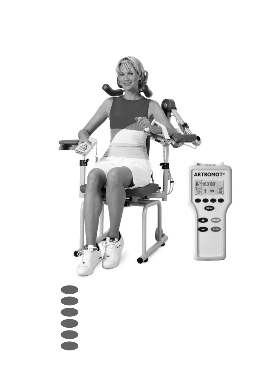
ARTROMOT®-S3
D
E
F
ES
I
NL
Gebrauchsanweisung
Operating Instructions
Mode d’emploi
Modo de empleo
Istruzioni per l’uso
Gebruiksaanwijzing
Page 2

Diese Seite ausklappen
Fold out this page
Déplier cette page
Desplegar esta página
Aprire questa pagina
Deze bladzijden uitvouwen
2
Page 3
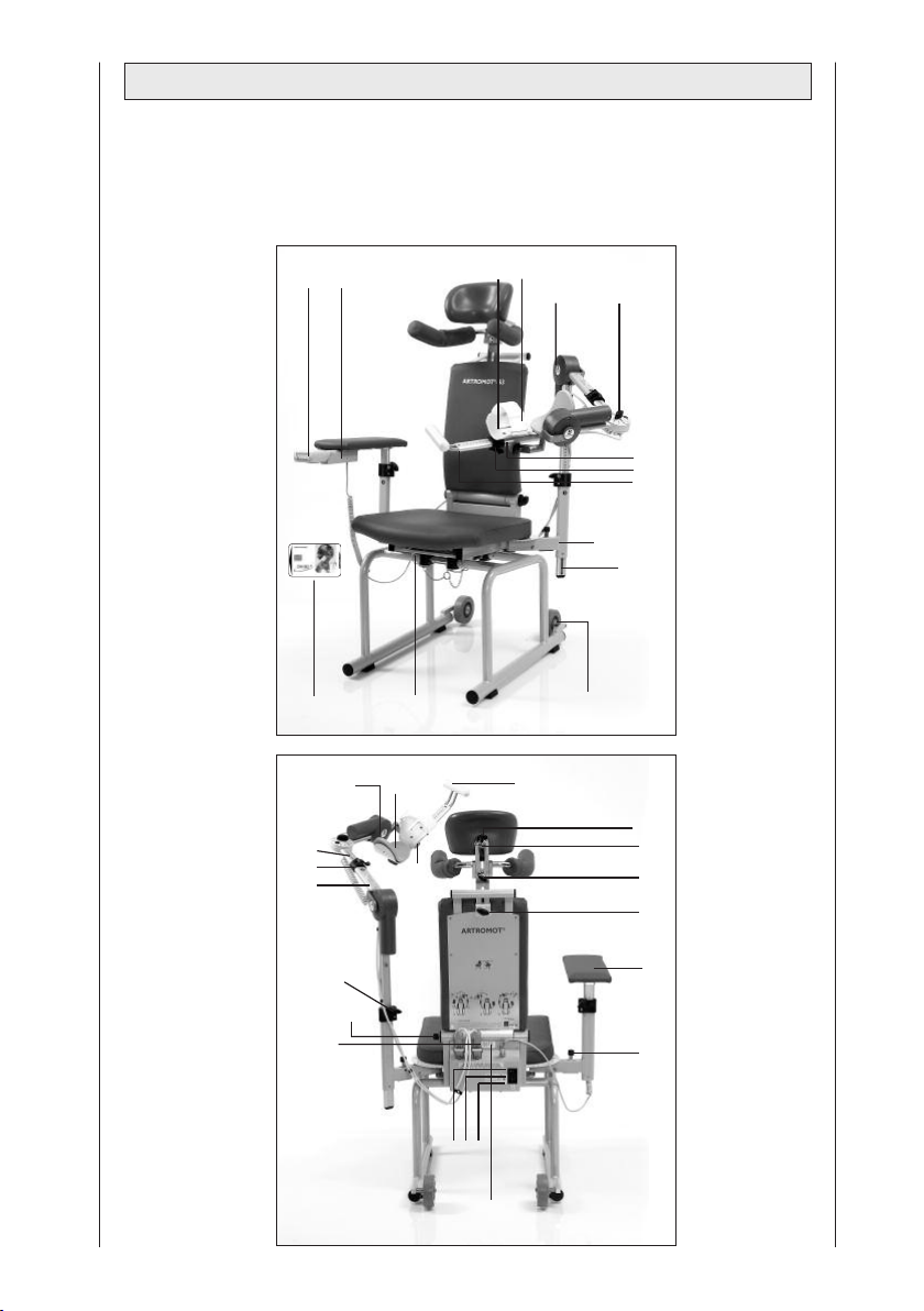
Gerätebeschreibung
Device description
Description de l’appareil
Descripción del aparato
1 3
2
34
Descrizione
dell’apparecchiatura
Beschrijving
24
23
16
20
25
26
27
13
15
5
19
18
17
22 29
21
14
10
9
28
33
30
31
32
4
12
8
76
11
3
Page 4

Inhalt
Gerätebeschreibung 3
®
Abbildungen zur Einstellung der ARTROMOT
-S3 252
Piktogrammubersicht 249
1. Informationen zum Einsatz der Bewegungsschiene 5
1.1 Einsatzmöglichkeiten 5
1.2 Therapieziele 5
1.3 Indikationen 5
1.4 Kontraindikationen 5
2. Beschreibung der ARTROMOT
®
-S3 6
2.1 Erklärung der Funktionselemente 6
2.2 Erklärung der Programmiereinheit 7
2.3 Erklärung der Piktogramme 10
2.4 Erklärung der Symbole (Anschlüsse und Typenschild) 11
3. Sicherheitshinweise 12
4. Gerät einstellen 15
4.1 Anschließen des Gerätes, Funktionskontrolle 15
4.2 Einstellen des Gerätes auf die Patientenmaße 16
5. Behandlungswerte einstellen 18
5.1 Allgemeine Programmierhinweise für die ARTROMOT
®
5.2 ARTROMOT
-S3 Standard-Version programmieren 20
®
-S3 18
5.3 Informationen zu den Behandlungswerten der Standard-Version 20
5.4 ARTROMOT®-S3 Comfort-Version programmieren 25
5.5 Informationen zu den Programmen der Comfort-Version 25
5.6 Anwendungs-/Programmierbeispiele 30
6. Pflege, Wartung, Transport, Umbau 33
6.1 Pflege 33
6.2 Wartung (Sicherungen auswechseln) 33
6.3 Transport 34
6.4 Umbau 36
7. Umwelthinweise 37
8. Technische Daten 37
9. IEC 60601-1-2:2001 38
9.1 Elektromagnetische Aussendung 38
9.2 Elektromagnetische Störfestigkeit 40
9.3 Empfohlene Schutzabstände 41
10. Kontakte 41
11. Technischer Service 42
11.1 Technische Hotline 42
11.2 Versand 42
11.3 Ersatzteile 42
12. Konformitätserklärung 43
4
Page 5

1. Informationen zum Einsatz der Bewegungsschiene
1.1 Einsatzmöglichkeiten
Die ARTROMOT®-S3 ist eine motorisierte Bewegungsschiene zur kontinuierlichen passiven Bewegung
(Continuous Passive Motion = CPM)
des Schultergelenks.
Ihr Einsatz ist sowohl in der Klink/Praxis
als auch im Mietservice eine wichtige
Ergänzung der medizinisch-therapeutischen Behandlung.
1.2 Therapieziele
Die Bewegungstherapie mit der Bewegungsschiene ARTROMOT
vor allem der Vermeidung von Immobilisationsschäden, der frühzeitigen
Rückgewinnung einer schmerzfreien
Gelenkbeweglichkeit sowie der Förderung eines rascheren Heilungsverlaufs
mit gutem funktionellem Ergebnis.
Weitere Ziele der Therapie sind:
- Verbesserung des Gelenkstoffwechsels
- Verhütung von Gelenksteifen (Arthrofibrose)
- Unterstützung des Aufbaus und der
Heilung von Knorpelarealen und
Bandschäden
- schnellere Ergussresorption
- verbesserte Lymph- und Blutzirkulation
- Vorbeugung von Thrombosen und
Embolien
®
-S3 dient
1.3 Indikationen
Die Bewegungsschiene eignet sich
zur Behandlung der häufigsten Verletzungen, postoperativer Zustände und
Erkrankungen des Schultergelenks,
wie zum Beispiel:
- Gelenkdistorsionen und -kontusionen
- Arthrotomien und Arthroskopien in
Kombination mit Synovektomie,
Arthrolyse oder anderen intraartikulären
Maßnahmen
- Arthroplastiken aller Art
- Gelenkmobilisation in Narkose
- operativ versorgte Frakturen, Pseudoarthrose, soweit übungsstabil
- Dekompressionsoperationen (Acromioplastik)
- Endoprothesenimplantationen
- Weichteileingriffe in der Achselhöhle
und im Bereich des Schultergürtels
- Tumoroperationen im Schulterbereich
1.4 Kontraindikationen
Nicht angewendet werden darf die
ARTROMOT
- Akut entzündlichen Gelenkveränderungen, soweit vom Arzt nicht ausdrücklich verordnet
- Spastischen Lähmungen
- Instabilen Osteosynthesen
®
-S3 bei:
Deutsch
5
Page 6
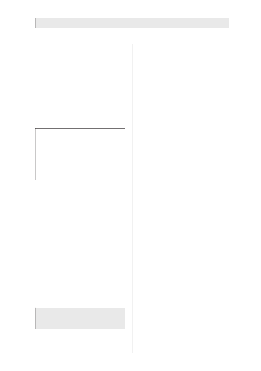
2. Beschreibung der ARTROMOT®-S3
Die motorisierte Bewegungsschiene
ermöglicht folgende Bewegungen im
Schultergelenk:
Add-/Abduktion 0° - 30° - 175°
Innen-/Außenrotation 90° - 0° - 90°
Elevation (Flexion) 0° - 30° - 175°
mit 60° - 90° angewinkeltem Ellenbogen
Ante-/Retroversion 0° -120 °
(Horizontal-Add-/Abduktion)
Nur manuell einstellbar
Sie ist beidseitig, mit Seitenumbau,
einsetzbar.
Hinweis!
Um eine eindeutige Darstellung der
aktuellen Position der Bewegungsschiene zu ermöglichen, werden die
Innenrotationswerte auf dem Display
und im weiteren Verlauf der Gebrauchsanweisung mit „–“ gekennzeichnet.
®
Die ARTROMOT
-S3 zeichnet sich,
unter anderem, durch folgende Merkmale aus:
- anatomisch korrekte Einstellbarkeit
- physiologische Bewegungsabläufe
- größtmögliche Bewegungsumfänge
- Programmiereinheit zur feinstufigen
Einstellung aller Behandlungswerte
- Chipkarte zum Speichern der programmierten Werte
- einfach zu transportieren
Bioverträglichkeit
®
Die Teile der ARTROMOT
-S3, die be-
stimmungsgemäß mit dem Patienten in
Berührung kommen, sind so ausgelegt,
dass sie die Bioverträglichkeitsanforderungen der anwendbaren Standards
erfüllen.
2.1 Erklärung der
Funktionselemente
Hinweis:
Bitte klappen Sie Seite 3 aus!
1. Programmiereinheit
2. Patienten-Chipkarte
3. Ablagefach für Programmiereinheit
4. Armauflage für gesunden Arm
5. Transportrollen
6. Anschluss für die
Geräteanschlussleitung
7. Hauptschalter ein/aus
8. Geräteschutzsicherung
9. Stecker für Bewegungselement
10 Flügelschraube zum Verstellen
der Rückenlehnenneigung
11. Umklappvorrichtung der Rückenlehne (Transportposition)
12. Verstellung für Ante-/Retroversion
(Horizontal-Add-/Abduktion)
13. Aufnahmerohr für Höheneinstellung
14. Klemmschraube für Höheneinstellung
15. Einschubrohr für Höheneinstellung
16. Motor A
17. Aufnahmerohr für
Längeneinstellung Oberarm
18. Klemmhebel für Längeneinstellung
Oberarm
19. Einschubrohr für Längeneinstellung
Oberarm
20. Klemmschraube für Winkeleinstellung Ellenbogen
21. Motor B
22. Ellenbogen-Auflageschale
23. Unterarm-Auflageschale
24. Gurt für Unterarmfixierung
25. Aufnahmerohr für Längeneinstellung
Unterarm
26. Klemmhebel für Längeneinstellung
Unterarm
27. Einschubrohr für Längeneinstellung
Unterarm
28. Klemmschraube für Schwenkmechanik
29. Handgriff
30. Tiefeneinstellung für Kopfstütze
31. Höheneinstellung für Schulterfixierung
32. Höheneinstellung für Patientenfixierung
1
1
33. Kugelgelenk für Kopfstütze
34. Sicherungssplinte
Technische Änderungen vorbehalten
(06/2007)
1
Gilt nur für ARTROMOT®-S3 comfort
6
1
1
Page 7
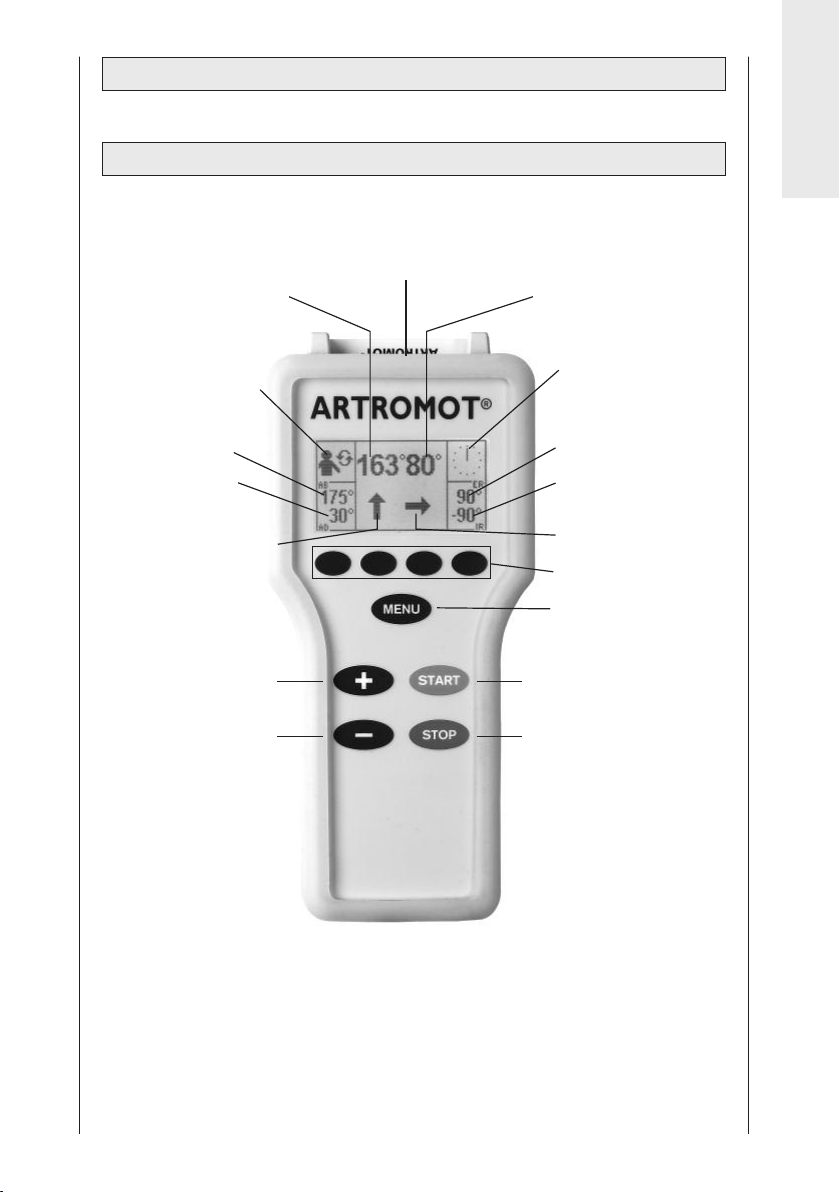
2.2 Erklärung der Programmiereinheit
2.2.1 Programmiereinheit im Normalbetrieb:
Patienten-Chipkarte
Aktueller Winkel Motor A
Programmiertes
Therapieprogramm
Programmierter
Abduktionswert
Programmierter
Adduktionswert
Aktuelle Laufrichtung
Motor A
„+“-Taste
Deutsch
Aktueller Winkel Motor B
Therapiezeitanzeige
Programmierter
Außenrotationswert
Programmierter
Innenrotationswert
Aktuelle Laufrichtung
Motor B
Parametertasten
MENÜ-Taste
START-Taste
„-“-Taste
STOP-Taste
7
Page 8
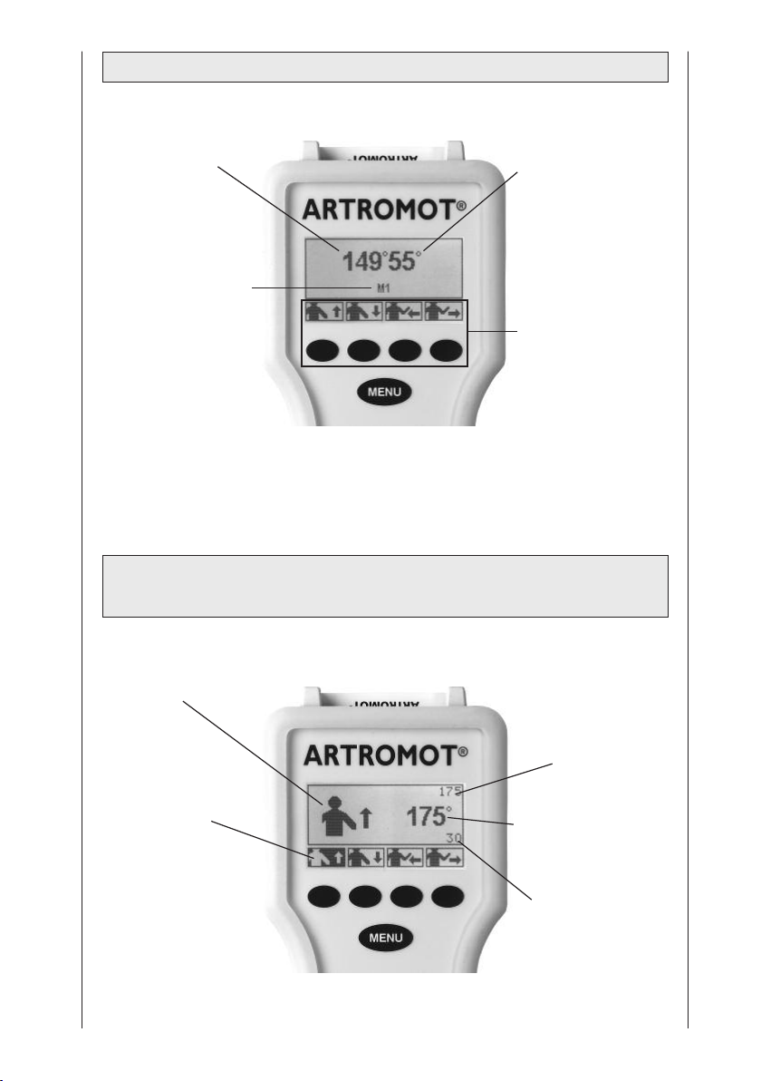
2.2.2 Programmiereinheit im MENU-Auswahlmodus
Aktueller Winkel der
Bewegungsschiene in
Abduktion/Adduktion
Aktuelle MENÜ-Ebene
2.2.3 Programmiereinheit im Programmiermodus
Bewegungsausmaß
Aktueller Winkel der
Bewegungsschiene in
Innen-/Außenrotation
Zur Auswahl
stehende Parameter
und dazugehörige
Parametertasten
Ausgewählte Funktion
Aktivierter Parameter
(hier Abduktion)
Aktueller
programmierter
Maximalwert der
Abduktion oder
Außenrotation (hier
Abduktion)
Aktueller Winkel der
Bewegungsschiene
Ab-/Adduktion oder
Innen-/Außenrotation
Aktueller programmierter Maximalwert
der
Adduktion/Innenrotati
on
(hier Adduktion)
8
Page 9
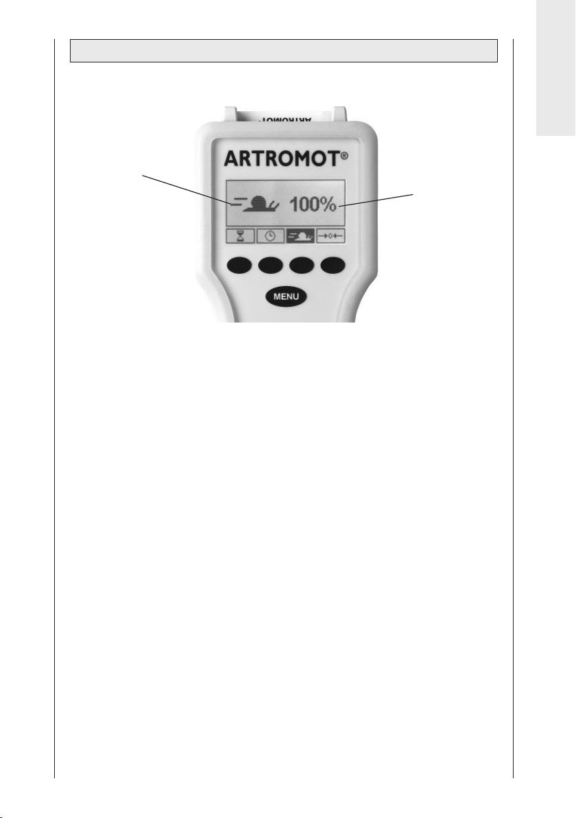
2.2.4 Programmiereinheit im Programmiermodus Allgemein
Deutsch
Ausgewählte Funktionen
Aktueller Zustand der
ausgewählten Funktion
(hier Geschwindigkeit)
9
Page 10
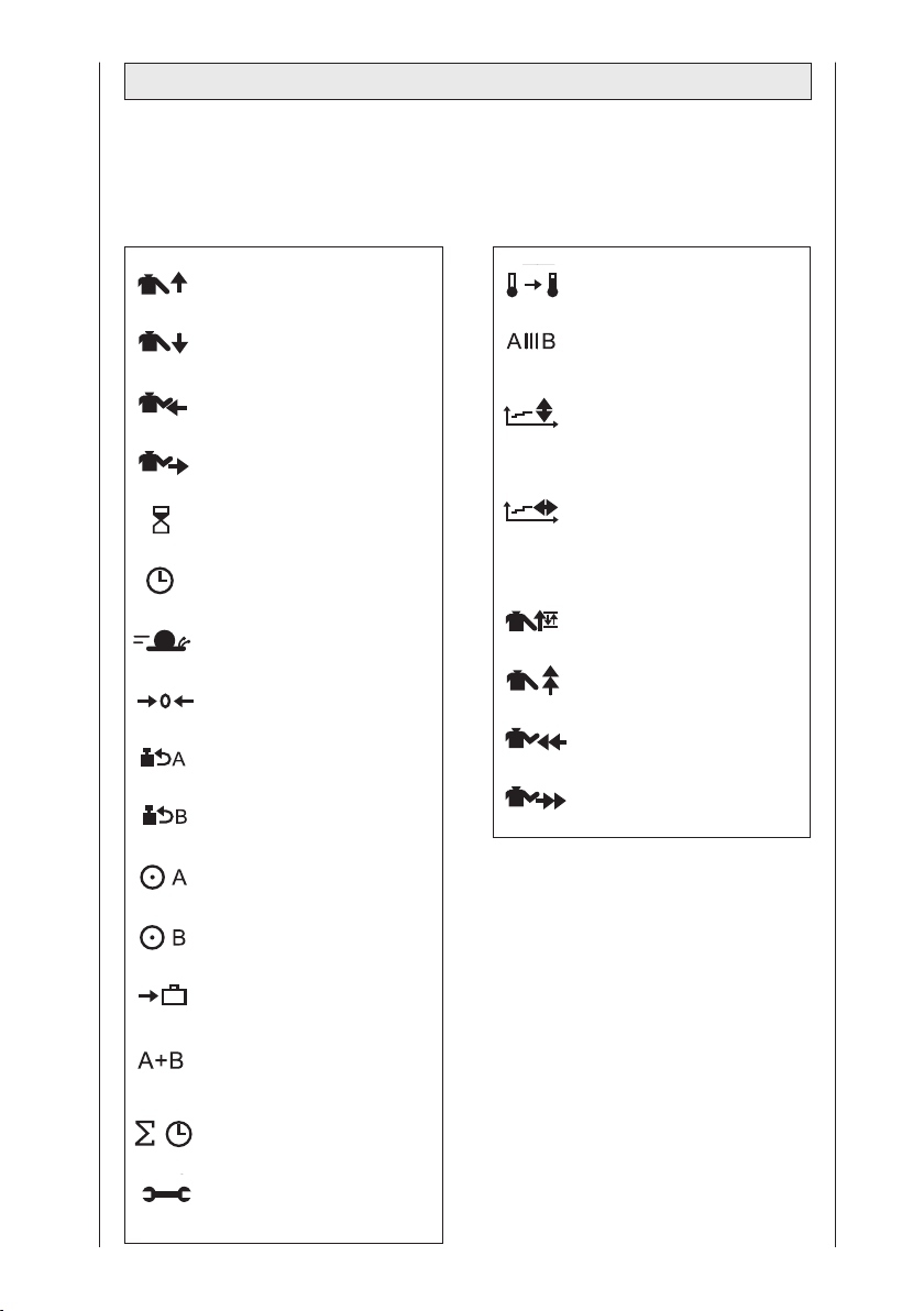
2.3 Erklärung der Piktogramme
Siehe auch Piktogrammübersicht, Seite 249.
Standard-Programme: Comfort-Programme:
Abduktion
Adduktion
Innenrotation
Außenrotation
Pause
Timer
Geschwindigkeit
Neuer Patient
Lastumkehr Motor A
Lastumkehr Motor B
Motor A Ein/Aus
Aufwärmprogramm
Isolationsprogramm
Therapieverlaufsdokumentation
Abduktion/Adduktion
Therapieverlaufsdokumentation
Innenrotation/
Außenrotation
Oszillation
Dehnung Abduktion
Dehnung Innenrotation
Dehnung Außenrotation
Motor B Ein/Aus
Transporteinstellung
Betriebsart
Synchron/Asynchron
Gesamttherapiezeit
Service-Menü
10
Page 11
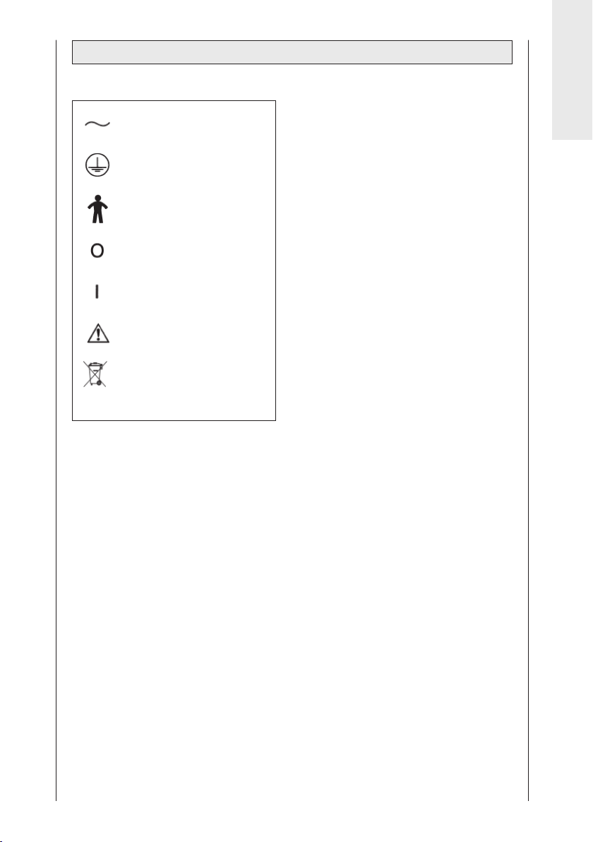
2.4 Erklärung der Symbole (Anschlüsse und Typenschild)
Wechselstrom
Schutzleiteranschluss
Anwendungsteil Typ B
Hauptschalter AUS
Hauptschalter EIN
Begleitpapiere beachten
Nicht mit dem unsortierten
Hausmüll entsorgen
Deutsch
11
Page 12
3. Sicherheitshinweise
Erläuterung
Lesen Sie die Sicherheitshinweise
unbedingt vor der Inbetriebnahme der
Bewegungsschiene. Die Sicherheitshinweise sind wie folgt gekennzeichnet:
Gefahr!
Macht auf eine unmittelbar drohende
Gefahr aufmerksam. Das Nichtbeachten führt zum Tod oder zu schwersten
Verletzungen.
Warnung!
Macht auf eine Gefährdung aufmerksam. Das Nichtbeachten kann zum
Tod oder zu schwersten Verletzungen
führen.
Vorsicht!
Macht auf eine möglicherweise
gefährliche Situation aufmerksam.
Das Nichtbeachten kann zu leichten
Verletzungen und/oder zur Beschädigung des Produkts führen.
Sicherheitshinweise
Gefahr!
Explosionsgefahr
Die ARTROMOT
den Betrieb in explosionsgefährdeten
Bereichen medizinisch genutzter
Räume bestimmt. Explosionsgefährdete
Bereiche können durch Verwendung
von brennbaren Anästhesiemitteln,
Hautreinigungs- und Hautdesinfektionsmitteln entstehen.
1
Gilt nur für ARTROMOT®-S3 comfort
®
-S3 ist nicht für
Warnung!
Patientengefährdung
− Die ARTROMOT
von autorisierten Personen
bedient werden. Autorisiert ist, wer
in die Bedienung des Gerätes
eingewiesen wurde und den Inhalt
dieser Gebrauchsanweisung kennt.
− Der Anwender hat sich vor jeder
Anwendung des Gerätes von
der Funktionssicherheit und dem
ordnungsgemäßen Zustand des
Gerätes zu überzeugen. Insbesondere sind Leitungen und Steckvorrichtungen auf Beschädigungen
zu überprüfen. Beschädigte Teile
müssen sofort ersetzt werden.
− Vor Behandlungsbeginn muss
ein Probelauf mit mehreren Bewegungszyklen ohne und anschließend
mit Patient durchgeführt werden.
Alle Einstellschrauben sind auf
festen Sitz zu prüfen.
− Die Therapie muss sofort abgebrochen werden, wenn Zweifel an
der korrekten Geräteeinstellung
und/oder Programmierung bestehen.
− Die anatomisch korrekte Einstel-
lung des Gerätes auf den Patienten
ist zu beachten. Dazu sind folgende
Einstellungen/Positionierungen zu
prüfen:
(siehe Nummerierung am Gerät):
1. Ante-/Retroversion
(Horizontal-Add-/Abduktion)
2. Höheneinstellung
3. Oberarm-Längeneinstellung
4. Ellenbogen-Winkeleinstellung
5. Unterarm-Längeneinstellung
6. Kopfstützeneinstellung
Bei Verwendung der
Patientenfixierungsoption
7. Höhen- und Tiefeneinstellung von
Kopfstütze und Schulterfixierung
12
®
-S3 darf nur
1
1
Page 13

− Die Einstellungen 1 bis 7 dürfen nur
geändert werden, wenn sich kein
Patient auf der Schiene befindet.
− Die Bewegung muss immer
schmerz- und reizfrei erfolgen.
− Der Patient muss während der
Einweisung und der Benutzung der
Schiene bei vollem Bewusstsein
sein.
− Die Wahl der zu programmierenden
Behandlungsparameter, einschließlich der einzusetzenden
Therapieprogramme, kann und
darf nur durch den behandelnden
Arzt oder Therapeuten getroffen
werden.
Im Einzelfall muss der Arzt oder
Therapeut entscheiden, ob die
Bewegungsschiene bei dem
Patienten eingesetzt werden darf.
− Die Programmiereinheit der
ARTROMOT
®
-S3 ist dem Patienten
zu erklären und muss sich in
erreichbarer Nähe des Patienten
befinden, damit dieser im Bedarfsfall die Therapie unterbrechen kann.
Bei Patienten, die die Programmiereinheit nicht bedienen können,
z. B. bei Lähmung, darf die Behandlung nur unter ständiger Betreuung
durch Fachpersonal vorgenommen
werden.
− Die Patienten-Chipkarte ist mit
dem Namen des Patienten zu
versehen und darf ausschließlich für
diesen verwendet werden. Wenn die
Patienten-Chipkarte für einen
anderen Patienten verwendet wird,
ist sicherzustellen, dass die Daten
des vorherigen Patienten gelöscht
werden
(Siehe Kapitel 4.1 und Kapitel 5.3,
Absatz „Neuer Patient“).
Es dürfen nur Original-Chipkarten
verwendet werden.
− Die ARTROMOT
®
-S3 darf nur mit
Zubehörartikeln betrieben werden,
die von ORMED freigegeben sind.
− Achten Sie darauf, dass keine
Körperteile oder Gegenstände
(wie Decken, Kissen, Kabel etc.) in
die beweglichen Teile der Schiene
gelangen können.
Warnung!
Stromschlaggefahr
Die folgenden Warnhinweise sind
unbedingt zu beachten. Ansonsten
besteht für Patient, Anwender und
Hilfspersonen Lebensgefahr.
− Vor der Inbetriebnahme ist sicherzu-
stellen, dass die ARTROMOT
Zimmertemperatur angenommen hat.
Wurde das Gerät bei Minusgraden
transportiert muss es ca. 2 Stunden
bei Zimmertemperatur gelagert
werden, bis evtl. vorhandenes
Kondenswasser abgetrocknet ist.
®
− Die ARTROMOT
-S3 darf nur
in trockenen Räumen betrieben
werden.
− Zum Trennen des Gerätes vom Netz
stets zuerst den Stecker aus der
Wandsteckdose ziehen, erst dann
die Anschlussleitung vom Gerät
trennen.
− Bei der Kopplung mit anderen
Geräten oder einer Zusammenstellung von medizinischen Systemen
muss sichergestellt sein, dass keine
Gefährdung durch die Summierung
von Ableitströmen auftreten kann.
Bei Rückfragen wenden Sie sich an
ORMED.
− Zur Stromzuführung dürfen keine
Verlängerungsleitungen mit Mehrfachsteckdosen verwendet werden.
Die ARTROMOT
®
-S3 darf nur an
eine ordnungsgemäß installierte
Schutzkontaktsteckdose ange-
schlossen werden. Vor dem
Anschließen muss die Geräteanschlussleitung vollkommen entrollt
und so verlegt werden, dass sie
während des Betriebes nicht zwischen
bewegliche Teile gelangen kann.
®
-S3
Deutsch
13
Page 14

− Vor allen Reinigungs- und
Instandsetzungsarbeiten muss der
Netzstecker aus der Steckdose
gezogen werden.
− Es darf keine Flüssigkeit in die
Bewegungsschiene oder in die
Programmiereinheit eindringen.
Ist Flüssigkeit eingedrungen, darf
die ARTROMOT
nach einer Überprüfung durch den
Kundendienst in Betrieb genommen
werden.
®
-S3 erst wieder
Vorsicht!
Vermeiden von Scheuer- und Druckstellen Achten Sie bei adipösen,
besonders großen und sehr kleinen
Patienten auf die Vermeidung von
Scheuer- und Druckstellen.
Patientengefährdung, Beschädigung
der Schiene Die Schiene darf nicht
zum Transportieren von Personen
verwendet werden.
Warnung!
Funktionsstörungen des Gerätes
− Magnetische und elektrische Felder
können die Funktion des Gerätes
beeinflussen. Achten Sie beim
Betreiben des Gerätes darauf, dass
alle Fremdgeräte, die in der Nähe
betrieben werden, ihren relevanten
EMV-Anforderungen entsprechen.
Röntgengeräte, Tomographen,
Funkanlagen, Handys usw. können
andere Geräte stören, weil sie
zulassungsgemäß höhere elektromagnetische Störungen abgeben
dürfen.
Halten Sie von solchen Geräten
ausreichend Abstand, führen Sie
vor der Anwendung eine Funktionskontrolle durch.
− Instandsetzungs- und Wartungs-
arbeiten dürfen nur von autorisierten
Personen durchgeführt werden.
− Sämtliche Leitungen sind so zu
verlegen, dass sie während des
Betriebes nicht in bewegliche Teile
gelangen können und dass keine
Stolpergefahr besteht.
− Kontrollieren Sie die
ARTROMOT
einmal pro Jahr auf mögliche
Schäden oder lose Verbindungen.
®
-S3 mindestens
Vorsicht!
Geräteschaden
− Vergewissern Sie sich, dass die
Kennwerte Ihres Spannungsnetzes
mit den Spannungs- und Frequenzangaben des Typenschildes
übereinstimmen.
− Die maximale Dauerbelastung
des Sitzfläche beträgt 150 kg.
− Achten Sie darauf, dass keine
Gegenstände (wie Decken, Kissen,
Kabel etc.) in die beweglichen
Teile der Schiene gelangen können.
− Setzen Sie die ARTROMOT
keiner direkten Sonnenbestrahlung
aus, da sich sonst Komponenten
unzulässig stark erwärmen können.
− Beachten Sie, dass die Stecker
nur in einer bestimmten Stellung
eingesteckt werden können und
sichern Sie die Steckverbindung
immer mit der Verriegelung.
®
-S3
14
Page 15
4. Gerät einstellen
Hinweis: Klappen Sie bitte zur
Veranschaulichung der einzelnen
Schritte Seite 3 und 252 aus!
4.1 Anschließen des Gerätes,
Funktionskontrolle
1. Schließen Sie die Geräteanschlussleitung an die Anschlussbuchse (6) des
Gerätes an und stecken Sie anschließend den Netzstecker in eine Schutzkontakt-Steckdose (100-240 Volt,
50/60 Hertz).
2. Schalten Sie den Hauptschalter (7) ein.
3. Bringen Sie nun die Schiene wie folgt
in ihre Grundposition:
Ersteinstellung bei neuen Patienten
Notieren Sie den Namen des Patienten
auf der Rückseite der Chipkarte.
Schieben Sie die Original-PatientenChipkarte (2) in die Programmiereinheit
(1).
Drücken Sie auf der Programmiereinheit
3 Mal die Taste MENU, bis Sie
in die Programmierebene 3 gelangen
(mit jedem Drücken wechseln Sie in die
nächste Ebene).
Drücken Sie die Parametertaste „Neuer
Patient“ und aktivieren Sie
diese Funktion (Häkchen im Kreis
neben der Funktion).
Drücken Sie die Taste START. Die
Grundposition wird automatisch
angefahren.
Einstellung mit bereits
programmierter Chipkarte
Schieben Sie die Original-PatientenChipkarte (2) in die Programmiereinheit
(1).
Drücken Sie die Taste START.
Die Startposition (maximaler Adduktionswert, Mittelwert Innen-/Außenrotation) wird automatisch angefahren.
Funktionskontrolle:
Wenn Sie die Programmiereinheit wie
oben beschrieben bedienen können
und die ARTROMOT
position fährt (siehe Werte der Grundposition in Kapitel 5.3), dann arbeitet
das Gerät einwandfrei.
Das Gerät führt während des Betriebs
kontinuierlich intern eine Funktionskontrolle durch. Erkennt es dabei einen
Fehler, so
− ertönt ein Warnsignal
− schaltet es unverzüglich ab
− erscheint auf dem Display der
Hinweis „ERROR“ sowie ein Fehlercode (z. B. ERROR 5).
In diesem Fall können Sie einen
Neustart durch kurzes Aus- und
Einschalten des Hauptschalters
versuchen. Sollte die Fehlermeldung
bestehen bleiben, dürfen Sie das
Gerät erst nach einer Überprüfung
durch den Kundendienst wieder
benützen.
®
-S3 in die Grund-
Deutsch
Wenn Sie sich davon überzeugt haben,
dass die ARTROMOT
funktioniert, dann lassen Sie den
Patienten auf der ARTROMOT®-S3 Platz
nehmen.
15
®
-S3 einwandfrei
Page 16
4.2 Einstellen des Gerätes
auf die Patientenmaße
Hinweis!
Bei den folgenden Einstellungen sollte
sich der Patientenarm noch nicht auf
der Armauflage befinden. Erst wenn
Sie die Schiene auf die Patientenmaße
voreingestellt haben, müssen Sie eine
Einstellungskontrolle bzw. Feinjustierung
mit dem Patientenarm in der Armauflage durchführen.
Die Einstellungen sind von 1 bis 5
nummeriert. Auf der Schiene sind
diese Nummern als Orientierungshilfe
angebracht. Führen Sie die Einstellungen immer in dieser Reihenfolge
durch.
Notieren Sie die Einstellwerte auf der
Rückseite der Patienten-Chipkarte.
Bevor Sie mit der genauen Einstellung
der ARTROMOT
maße beginnen, muss die Schiene
ggf. für die linke oder rechte Schulter
umgebaut werden.
(siehe Kapitel 6.4 „Umbau“)
®
-S3 auf die Patienten-
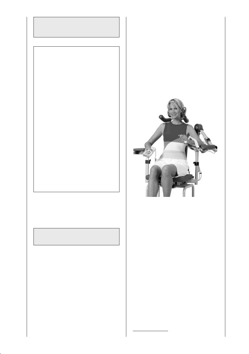
• Stellen Sie anschließend die Kopf-
1
stütze
ein: Höhenverstellung mit
Klemmschraube (32), Tiefenverstellung
mit Klemmschraube (30), Feinjustierung
mit Kugelgelenk (33).
• Positionieren Sie die Schulterfixie-
1
mit Klemmschraube (31)
rung
ca. 1 cm über den Schultern.
• Stellen Sie die Armauflage für den
gesunden Arm in der Höhe so ein,
dass der Patient gerade sitzt
(Klemmschraube 14).
Vor Beginn der Behandlung sind
folgende Einstellungen vorzunehmen:
Rückenlehne, Kopfstütze,
Schulterfixierung, Armauflage
Bevor Sie mit den eigentlichen Einstellungen beginnen, müssen Sie den
Patienten in eine korrekte anatomische
Position bringen.
• Öffnen Sie die Flügelschraube (10)
und stellen Sie die Rückenlehne in
eine für den Patienten angenehme
Position. (Abb. F)
Anatomisch korrekte Einstellung
1
Gilt nur für ARTROMOT®-S3 comfort
16
Page 17

Ante-/Retroversion (Abb. A)
†
(Horizontal-Add-/Abduktion)
Ziel der Einstellung ist eine möglichst
komfortable Positionierung des Patienten.
• Drücken Sie den Rastknopf (12) und
achten Sie darauf, dass er nach der
Einstellung wieder richtig einrastet.
Höheneinstellung (Abb. B)
Œ
Bevor Sie die Klemmschraube (14)
lösen, müssen Sie den beweglichen Teil
der Schiene festhalten, damit
er nicht nach unten fällt; am besten am
Aufnahmerohr für die Längenverstellung
(17).
• Stellen Sie die Höhe so ein, dass die
Achse von Motor A mit dem Schultergelenk-Drehpunkt fluchtet (Abb. S.
16). Der Drehpunkt von Motor A muss
mit dem Drehpunkt des Schultergelenks übereinstimmen.
• Ziehen Sie die Klemmschraube wieder
fest.
Oberarmlänge (Abb. C)
Å
Hinweis!
Eine Veränderung des Ellenbogenwinkels auf weniger oder mehr als 90°
Flexion hat eine Änderung der Oberarmlängen-Einstellung zur Folge.
Unterarmlänge (Abb. E)
ì
• Lösen Sie den Klemmhebel (26)
und ziehen Sie den Handgriff soweit
heraus, bis der Unterarm bequem
zwischen Ellenbogen-Auflageschale
und Handgriff Platz findet.
• Schließen Sie den Klemmhebel
wieder.
Hinweis!
Zum genauen Anpassen kann die
Neigung der Armauflage verstellt
werden.
Lösen Sie dazu die Klemmschraube
(28) unter der Armauflage. Stellen
Sie die gewünschte Neigung ein und
schließen Sie die Klemmschraube
wieder.
Deutsch
Die Verstellvorrichtung für die
Oberarmlänge ist selbsthemmend.
Sie müssen beim Verstellen gleichzeitig
den Motor B leicht anheben und darauf
achten, dass das Einschubrohr nicht
verkantet.
• Lösen Sie den Klemmhebel (18)
und heben Sie den Motor während
des Einstellens leicht an.
• Schließen Sie den Klemmhebel
wieder.
Ellenbogenwinkel (Abb. D)
è
In der Regel wird der Ellenbogen auf
90° bis 60° Flexion eingestellt.
• Lösen Sie die Klemmschraube (20).
Heben Sie zum leichteren Verstellen
den Motor B minimal an.
• Nehmen Sie die gewünschte
Einstellung vor und schließen Sie
die Klemmschraube wieder.
Kontrolle der Einstellungen,
Feinjustage
• Lagern Sie den Patientenarm in der
Armauflage.
• Kontrollieren Sie die Einstellungen 1
bis 5 und stellen Sie sicher, dass
− der Drehpunkt von Motor A mit
dem Drehpunkt des Schultergelenks übereinstimmt
− die Achse von Motor B, der Mittel-
punkt des Ellenbogengelenks und
der Mittelpunkt des Schultergelenks eine Gerade bilden.
Zum genauen Anpassen kann die
Armauflage zusätzlich in Höhe und
Neigung verstellt werden. Lösen
Sie dazu die Klemmschraube (28)
unter der Armauflage.
• Stellen Sie sicher, dass alle Klemmschrauben festgezogen und alle
Klemmhebel korrekt geschlossen
sind.
17
Page 18

5. Behandlungswerte einstellen
Warnung!
Patientengefährdung
Vor Behandlungsbeginn muss ein
Probelauf mit mehreren Bewegungs-
zyklen ohne Patient durchgeführt
werden. Führen Sie danach einen
Probelauf mit Patient durch und achten
Sie auf schmerzfreie Bewegungen.
Hinweis: Siehe auch 2.2 und 2.3,
sowie Seite 249.
Hinweis!
Die Programmierung ist nur mit
eingesteckter Patienten-Chipkarte
möglich.
Informationen zu den Behandlungswerten und zum Programmieren der
Funktionen und Sonderfunktionen
finden Sie in den Kapiteln 5.1 bis 5.5.
Programmierbeispiele finden Sie im
Kapitel 5.6.
Wichtig!
Die Programmiereinheit
ARTROMOT®-S3 „Graphik“ kann
an alle Produkte der ARTROMOT
Schulterserie ab Seriennummer
größer 3000 angeschlossen werden.
Ein Tauschen der Chipkarten
zwischen den Versionen „Text“
und „Graphik“ ist möglich.
Zu beachten ist hierbei:
1. Soll eine Programmiereinheit der
Version „Graphik“ mit einer formatierten Chipkarte der Version „Text“
bedient werden, so
- bleibt die Spracheinstellung der
„Text“-Version erhalten; sie ist
für den Betrieb der „Graphik“Version unerheblich.
®
- wird automatisch die in der
„Text“-Version gespeicherte
Lastumkehr für beide Motoren
übernommen.
- ist die Tastensperre inaktiv.
2. Soll eine Programmiereinheit der
Version „Text“ mit einer formatierten Chipkarte der Version „Graphik“
bedient werden, so
- wird die Spracheinstellung
automatisch auf die Werkseinstellung – Deutsch – gesetzt.
- wird automatisch die für Motor A
in der Version „Graphik“ gespeicherte Lastumkehr für beide
Motoren übernommen.
- bleibt eine in der Version „Gra-
phik“ eventuell eingestellte
Tastensperre erhalten; für den
Betrieb der Version „Text“ hat
sie keine Auswirkungen, sie ist in
der Version „Text“ nicht
vorgesehen.
5.1 Allgemeine Programmierhinweise für die
ARTROMOT®-S3
1. Durch kurzes Drücken der Taste
MENU auf Ihrer Programmiereinheit
wechseln Sie in den Programmiermodus.
2. Die einzelnen Behandlungsparameter
und Funktionen sind auf vier (Standard-Version) bzw. auf sechs (Comfort-Version) verschiedene Programmierebenen verteilt (4 pro Ebene).
Zum Programmieren eines Parameters müssen Sie die entsprechende
Programmierebene aufrufen. Das
geschieht ebenfalls mit der Taste
MENU. Mit jedem Drücken wechseln
Sie in die nächste Ebene. Welche
Programmierebene Sie aufgerufen
haben, wird in der Mitte des Displays
mit M1, M2 usw. angezeigt.
18
Page 19
3. Den jeweiligen Behandlungsparameter bzw. die Funktionen rufen Sie mit
einer der 4 Parametertasten unterhalb des Displays auf. Welche
Parameter bzw. Funktionen den 4
Parametertasten jeweils zugeordnet
sind, wird durch die Symbole darüber
angezeigt.
Sobald Sie einen Parameter durch
Drücken der entsprechenden Parametertaste auswählen
• wird das entsprechende Symbol
groß im Display eingeblendet
• wird der aktuell eingestellte Wert
eingeblendet
• wird das Symbol über der
Parametertaste invers dargestellt.
4. Mit den Tasten + / - verändern Sie den
Wert (wenn Sie die Taste gedrückt
halten läuft der Wert schnell durch).
Einige Funktionen bzw. Sonderfunktionen werden lediglich aktiviert oder
deaktiviert. Dies geschieht entweder
durch erneutes Drücken der entsprechenden Parametertaste oder mit
den Tasten + / -. Wenn der Parameter
aktiviert ist, erscheint ein Häkchen im
Kreis neben dem Symbol.
5. Wenn Sie alle Parameter programmiert haben, speichern Sie die
Werte mit der Taste STOP.
6. Drücken Sie anschließend die Taste
START: ARTROMOT
®
-S3 überprüft
die eingestellten Werte, fährt in die
Mittelposition zwischen eingestelltem
Innenrotations- und Außenrotationswert sowie zum maximal eingestellten Adduktionswert und stoppt.
7. Drücken Sie erneut die Taste START,
um mit der Behandlung zu beginnen.
Die Schiene fährt anschließend
im Synchron-Modus zunächst zum
maximalen Innenrotationswert. Dann
wird zeitgleich der maximale Außenrotationswert zusammen mit dem
maximalen Abduktionswert angefahren
und anschließend der maximale
Adduktionswert zusammen mit dem
maximalen Innenrotationswert. Nach
Erreichen dieser Position beginnt der
Bewegungszyklus erneut durch das
Anfahren des maximalen Abduktionswertes zusammen mit dem maximalen Außenrotationswert.
Im Asynchron-Modus beginnt
unmittelbar nach Betätigen der
Taste START ein zufallsgenerierter
Lauf beider Motoren, wobei jeder
Motor jeweils nach Erreichen der
Maximalwerte die Laufrichtung ändert.
Hinweis!
- Eine Beschreibung der Parameter
finden Sie in den Abschnitten 5.3
und 5.5.
- Sie können sich die eingestellten
Parameter durch Drücken der
entsprechenden Parametertaste
anzeigen lassen. Dazu müssen Sie
zuvor jedoch die Taste STOP
drücken und auf die jeweilige MenüEbene wechseln.
- Um ein versehentliches Verstellen
der Parameter zu verhindern, können
Sie durch gleichzeitiges Drücken der
Tasten + und – die Tasten sperren.
Zum Entriegeln drücken Sie die
beiden Tasten noch einmal.
- Die Daten auf der Patienten-Chipkarte werden mit der Funktion
„Neuer Patient“ automatisch gelöscht.
Durch Drücken der Taste STOP am
Ende des Programmierens werden die
Einstellungen automatisch auch auf
der Patienten-Chipkarte gespeichert.
- Not-Aus-Funktion: Sobald während
der Behandlung eine beliebige Taste
gedrückt wird, schaltet
ARTROMOT
Die Behandlung kann durch Drücken
der Taste START wieder fortgesetzt
werden. Dabei wechselt das Gerät
automatisch die Bewegungsrichtung
Patienten mit
programmierter Chipkarte
• Nehmen Sie zunächst die mechanischen Einstellungen vor.
• Schieben Sie anschließend die
Chipkarte ein (der Patient darf sich
noch nicht auf der Bewegungsschiene
befinden).
19
®
-S3 unverzüglich ab.
Deutsch
Page 20
• Drücken Sie die Taste START: die
Bewegungsschiene fährt in die
Startposition der auf der Chipkarte
gespeicherten Parameter und stoppt.
• Lagern Sie anschließend den Patienten auf der Bewegungsschiene und
drücken Sie START, um mit der
Behandlung zu beginnen.
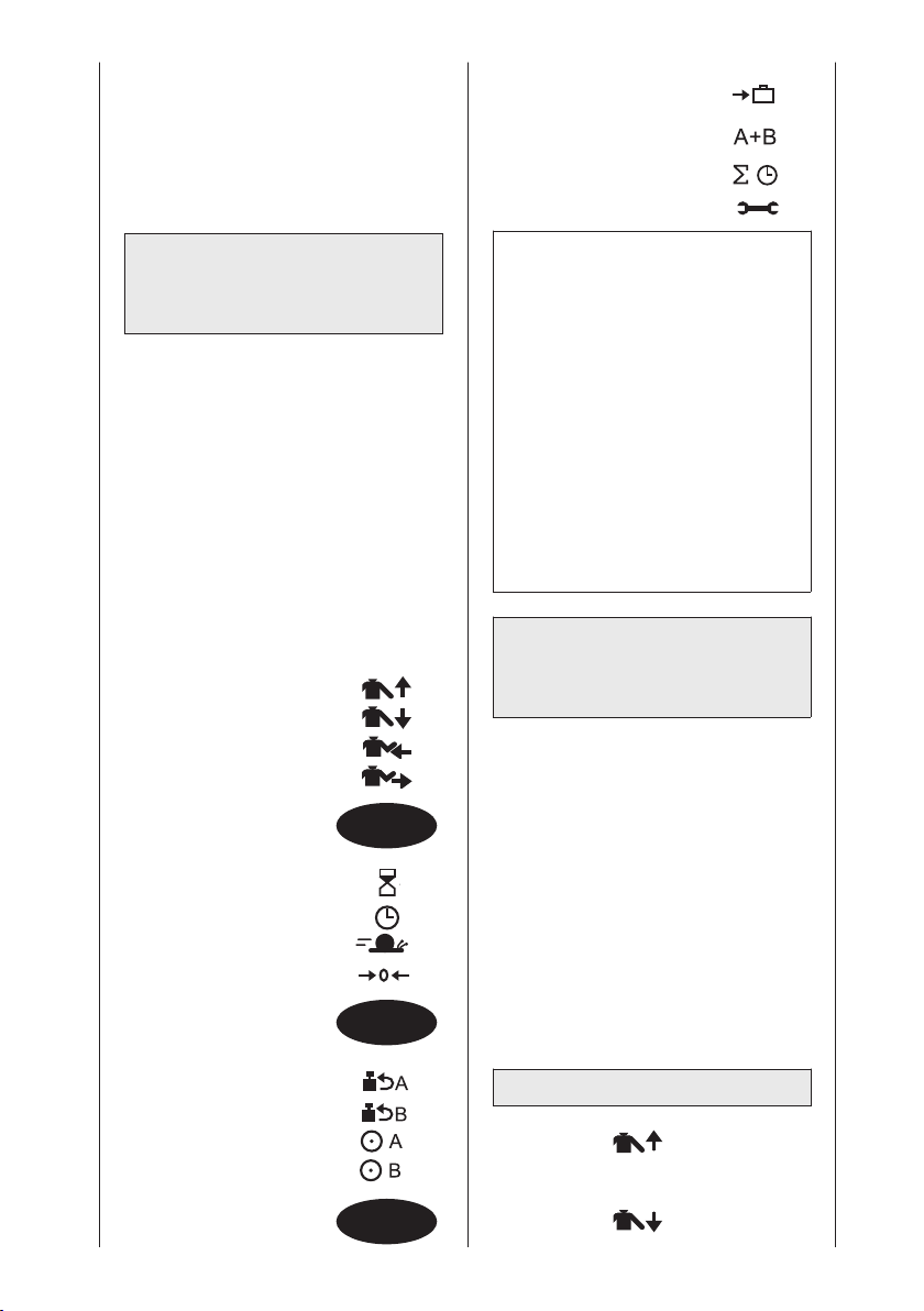
EBENE 4:
- Transporteinstellung
- Betriebsart
Synchron/Asynchron
- Gesamttherapiezeit
- Service-Menü
5.2 ARTROMOT®-S3
Standard-Version
programmieren
Die Programmierung der einzelnen
Einstellungen der ARTROMOT®-S3
Standard erfolgt auf mehreren
Programmierebenen.
Ein Wechsel zwischen den einzelnen
Ebenen ist durch wiederholtes Drücken
der MENU-Taste möglich.
Die jeweils aktuell gewählte Ebene
erscheint auf dem Display.
Folgende Behandlungswerte, Einstel-
lungen und Anzeigen können über die
Programmiereinheit (1)
eingegeben/abgerufen werden:
EBENE 1:
- Abduktion
- Adduktion
- Innenrotation
- Außenrotation
MENU
EBENE 2:
- Pause
- Timer (Therapiezeit)
- Geschwindigkeit
- Neuer Patient
MENU
EBENE 3:
- Lastumkehr Motor A
- Lastumkehr Motor B
- Motor A Ein/Aus
- Motor B Ein/Aus
Hinweis!
• Während der Einstellung der
Werte fährt das Gerät in den
eingestellten Bereich. So kann der
schmerzfreie Bewegungsumfang
einfach und schnell erfasst werden.
• Bei der Bewegungsschiene
ARTROMOT
zusätzlich Sonderfunktionen
programmiert bzw. abgerufen
werden (siehe Kapitel 5.4 und 5.5).
• Jeweils der letzte eingegebene
Winkel bei der Programmierung
der jeweiligen Bewegungsrichtung
wird umgehend gespeichert.
®
-S3 Comfort können
5.3 Informationen zu den
Behandlungswerten
der Standard-Version
• Die gewünschte Programmierebene
wählen Sie durch mehrmaliges
Drücken der MENU-Taste aus.
• Die Behandlungsparameter wählen Sie
mit der jeweiligen Parametertaste aus.
• Die Behandlungswerte verändern Sie
mit den + / – Tasten.
• Eine Funktion aktivieren/deaktivieren
Sie durch nochmaliges Drücken der
jeweiligen Parametertaste.
• Die vorgenommenen Einstellungen
speichern Sie durch Drücken der
STOP-Taste.
EBENE 1:
■ Abduktion
Maximaler Wert: 175 Grad
MENU
■ Adduktion
Maximaler Wert: 30 Grad
20
Page 21
Vorsicht!
Patientengefährdung
Bei der Verwendung der Schulterfixie-
rung dürfen nicht mehr als 80° Abduktion programmiert werden
■ Innenrotation
Maximaler Wert: - 90 Grad
■ Außenrotation
Maximaler Wert: 90 Grad
Hinweis!
• Die programmierten Werte und die
tatsächlich am Patienten gemessenen
Gradzahlen können geringfügig
variieren.
• Um einen physiologischen Bewegungsablauf zu gewährleisten,
werden im Synchron-Modus
folgende Werte zeitgleich angefahren:
- Maximaler Abduktionswert zeitgleich
mit maximalem Außenrotationswert
- Maximaler Adduktionswert zeit-
gleich mit maximalem Innenrotationswert.
• Um den physiologischen Bewegungsablauf bereits bei der Programmierung zu berücksichtigen, empfiehlt
es sich folgende Reihenfolge beim
Programmieren einzuhalten:
1. Maximaler Adduktionswert
2. Maximaler Innenrotationswert
3. Außenrotation
(zur Entlastung der Schulter)
= 0°
5. Maximaler Abduktionswert
6. Maximaler Außenrotationswert
• Im Synchron-Modus werden nach
dem Betätigen der Taste START
zunächst der maximale Adduktionswert und der Mittelwert zwischen
Innen- und Außenrotation angefahren.
Dort stoppt die Schiene, um ein
einfaches Einsteigen des Patienten
in die Schiene zu ermöglichen.
Nach erneutem Betätigen der
START-Taste (Behandlungsbeginn)
wird zuerst der maximale Innenrotationswert angefahren. Dabei steht
Motor A (Abduktion/Adduktion) still.
Nach Erreichen des maximalen
Innenrotationswertes fahren beide
Motoren (A und B) synchron den
jeweils maximalen Wert für Abduktion
und Außenrotation an. Nach Erreichen dieser Position beginnt der
Bewegungszyklus erneut durch
das Anfahren des maximalen
Adduktionswertes, zusammen mit
dem maximalen Innenrotationswert.
• Die Elevationsbewegung (Flexion)
wird mittels der Ab-/Adduktionswerte programmiert (mechanische
Einstellung siehe Kapitel 5.6
„Anwendungsbeispiele“).
• Die Einstellung der Ante- und
Retroversion hat manuell zu erfolgen. Mögliche Einstellungen sind:
Anteversion
(Horizontal-Adduktion): 120°
Retroversion
(Horizontal-Abduktion): 0°
EBENE 2:
■ Pausen
Die Pausen erfolgen jeweils an den
programmierten Maximalwerten.
Die zwei Pausenpunkte sind:
- Maximaler Adduktionswert zeitgleich mit maximalem Innenrotationswert
- Maximaler Abduktionswert zeitgleich mit maximalem Außenrotationswert.
Die Pausen sind in 1-SekundenSchritten von 0 bis 30 Sekunden
einstellbar.
Standardeinstellung: ohne Pause
Deutsch
21
Page 22
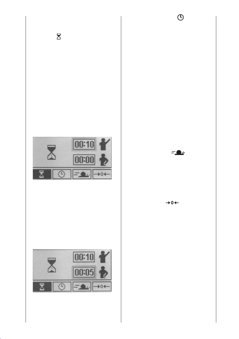
Die Pausen programmieren Sie wie folgt:
• Wählen Sie in der Menüebene 2
über die Parametertaste die Sonderfunktion an.
• Auf dem Display erscheint das
Symbol für die Sonderfunktion sowie
die Information über die aktuell
eingestellten Pausen.
Oben die eingestellte Zeit für die
Pause bei Abduktion/Außenrotation
Unten die eingestellte Zeit für die
Pause bei Adduktion/Innenrotation
(Display Bild).
Die Zeiteinstellung für die Pause bei
Abduktion/Außenrotation ist durch ein
Kästchen markiert.
• Verändern Sie den Wert für die Pause
Abduktion/Außenrotation durch
Drücken der Tasten „+“ oder „-“.
Wählen Sie hier z. B. 10 Sekunden.
■ Timer (Therapiezeit)
Standardeinstellung der Bewe-
gungsschiene ist Dauerbetrieb.
Als Symbol für den eingeschalteten
Dauerbetrieb wird rechts oben im
Display eine Uhr eingeblendet.
Die Uhr zeigt die verstrichene
Behandlungszeit an.
Im Dauerbetrieb muss das Gerät mit
der Taste STOP abgeschaltet werden.
Die Therapiezeit kann jedoch auch
frei in 1-Minuten-Schritten von 1 bis
300 Minuten gewählt werden.
Nach Ablauf der Therapiezeit schaltet
das Gerät automatisch in der Einstiegs-/Startposition (Maximalwert
Adduktion / Mittelwert Innen-/Außenrotation) der eingestellten Werte ab.
In diesem Fall wird anstelle der Uhr
ein Kreis eingeblendet. Durch Ausfüllen des Kreises wird die prozentual
verstrichene Therapiezeit angezeigt.
■ Geschwindigkeit
Die Geschwindigkeit ist in 1-%Schritten von 1 % bis 100 % wählbar.
100 % entspricht 230°/Minute
• Betätigen Sie anschließend erneut
die Parametertaste. Die Markierung
wechselt automatisch in die untere
Zeile zum Einstellen der Pausendauer bei Adduktion/Innenrotation.
Die Parametertaste dient bei dieser
Funktion ausschließlich zum
Umschalten zwischen den Pausen.
• Verändern Sie den Wert durch
Drücken der Tasten „+“ oder „-“.
Wählen Sie hier z. B. 5 Sekunden.
• Speichern Sie anschließend die
Programmierung durch Drücken der
Taste STOP und starten Sie die
Behandlung durch Drücken der
Taste START.
Standardeinstellung: 100 %
■ Neuer Patient
Wenn diese Funktion aktiviert wird,
fährt die Schiene in die Grundposition.
Aktivieren Sie die Funktion und
drücken Sie START:
− die Grundposition wird angefahren
− die vorhandenen Behandlungsparameter werden gelöscht
− alle auf der Chipkarte gespeicherten Werte werden gelöscht
− Die Schiene stoppt in den
Mittelpositionen der Abduktion/
Adduktion und Innen-/Außenrotation Winkelwerten.
Mit der Funktion „Neuer Patient“
(Grundposition) werden folgende
Einstellungen vorgenommen:
22
Page 23
- Abduktion: 41°
- Adduktion: 39°
- Innenrotation: 1°
- Außenrotation: -1°
- Pausen: 0
- Timer: Dauerbetrieb
- Geschwindigkeit: 100 %
- Lastumkehr Motor A: 25
- Lastumkehr Motor B: 25
- Motor A: aktiviert
- Motor B: aktiviert
- Betriebsart Synchron: aktiviert
- Gesamttherapiezeit: 0
- Sonderfunktionen: deaktiviert
EBENE 3:
■ Lastumkehr Motor A
(Sicherheitsschaltung)
Das Gerät schaltet automatisch beide
Motoren in die entgegen gesetzte
Bewegungsrichtung, wenn der
Widerstand (Last) durch den Patienten
die eingestellte Stufe überschreitet
Einstellbare Stufen für die Umkehrschaltung: 1 - 25. Bei Stufe 1 genügt
ein leichter Widerstand zum
Umschalten, bei Stufe 25 ist ein
großer Widerstand erforderlich.
Standardeinstellung: Stufe 25
■ Lastumkehr Motor B
(Sicherheitsschaltung)
Das Gerät schaltet automatisch beide
Motoren in die entgegen gesetzte
Bewegungsrichtung, wenn der
Widerstand (Last) durch den Patienten die eingestellte Stufe überschreitet.
Einstellbare Stufen für die Umkehrschaltung: 1 - 25. Bei Stufe 1 genügt
ein leichter Widerstand zum
Umschalten, bei Stufe 25 ist ein
großer Widerstand erforderlich.
Standardeinstellung: Stufe 25
Vorsicht!
Patientengefährdung
Die Lastumkehr dient ausschließlich
als Sicherheitsmaßnahme bei Krämpfen, Spasmen, Gelenkblockaden u. Ä.
Der Hersteller übernimmt bei Missbrauch keine Haftung.
■ Motor A Ein/Aus
Um eine vollkommen isolierte
Bewegung zu ermöglichen, können
die Motoren einzeln ein- und ausgeschaltet werden. Motor A betreibt
die Adduktion und Abduktion,
Motor B betreibt die Innenrotation
und Außenrotation.
Für eine isolierte Innen-/Außenrotationsbewegung, Motor A in die
gewünschte Position programmieren
(Ab-/Adduktion) und anschließend
deaktivieren.
Das Display zeigt im Normalbetrieb
der Schiene während der Therapie
das Symbol „OFF“ statt der programmierten Winkel für Ad- und Abduktion
an.
Standardeinstellung: Motor A
aktiviert
■ Motor B Ein/Aus
Um eine vollkommen isolierte Bewegung zu ermöglichen, können die
Motoren einzeln ein- und ausgeschaltet werden. Motor A betreibt die
Adduktion und Abduktion, Motor B
betreibt die Innenrotation und Außenrotation.
Für eine isolierte Ad- und Abduktionsbewegung, Motor B in die
gewünschte Position programmieren
(Innen-/Außenrotation) und anschließend deaktivieren.
Das Display zeigt im Normalbetrieb
der Schiene während der Therapie
das Symbol „OFF“ statt der programmierten Winkel für Innen- und Außenrotation an.
Standardeinstellung: Motor B
aktiviert
Deutsch
23
Page 24
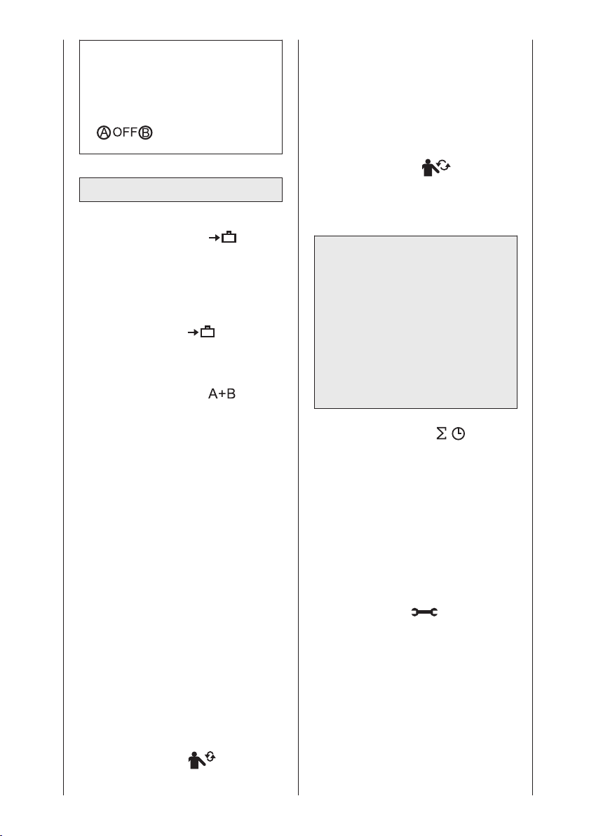
Hinweis!
• Beachten Sie bitte, dass immer ein
Motor (A oder B) eingeschaltet ist.
Ansonsten erscheint nach Drücken
von START auf dem Display:
Asynchron:
Beide Motoren laufen unabhängig im
jeweils eingestellten Bewegungsumfang.
Um den Betriebsmodus „Asynchron“
zu wählen, deaktivieren Sie die
Betriebsart „Synchron“.
Im Betriebsmodus wird der Asynchronbetrieb im linken oberen Feld
durch das Symbol angezeigt.
EBENE 4:
■ Transporteinstellung
Wenn diese Funktion aktiviert wird,
fährt die Schiene in die zum Verpacken optimale Position. Aktivieren Sie
die Funktion und drücken Sie START.
Die Transporteinstellung wird angefahren. Im linken oberen Feld des
Displays erscheint (Siehe auch
6 „Transport“)
■ Betriebsart
Synchron/Asynchron
Die Motoren A und B können synchron oder asynchron geschaltet
werden.
Synchron:
Motor A und B führen eine synchronisierte Bewegung gemäß dem physiologischen Bewegungsmuster des
Schultergelenks wie folgt aus:
Aus der Einstiegsposition (Maximalwert Adduktion / Mittelwert Innenund Außenrotation) wird zunächst der
maximale Innenrotationswert angefahren. Dann wird zeitgleich der
maximale Abduktionswert zusammen
mit dem maximalen Außenrotationswert angefahren und anschließend
wieder der maximale Adduktionswert
zusammen mit dem maximalen
Innenrotationswert. Nach Erreichen
dieser Position beginnt der Bewegungszyklus erneut durch das
zeitgleiche Anfahren des maximalen
Abduktionswerts zusammen mit dem
maximalen Außenrotationswert.
Im Betriebsmodus wird der Synchronbetrieb im linken oberen Feld
durch das Symbol angezeigt.
Standardeinstellung: „Synchron“
aktiviert
Vorsicht!
Patientengefährdung
Wir empfehlen grundsätzlich den
synchronen Betrieb. Die Verwendung
der asynchronen Betriebsart kann
medizinisch/therapeutisch indiziert
sein. Die asynchrone Betriebsart
bedarf besonderer Sorgfalt und
Aufmerksamkeit seitens der behandelnden Person, um eine Gefährdung
des Patienten auszuschließen.
■ Gesamttherapiezeit
Unter dem Menüpunkt „Gesamttherapiezeit“ kann die gesamte
Behandlungsdauer (Gesamtdauer der
einzelnen Therapiesitzungen) je Patient
abgerufen werden.
Löschen der gespeicherten Therapiedauer.
Halten Sie die Parametertaste für 5
Sekunden gedrückt oder aktivieren
Sie die Funktion „Neuer Patient“.
■ Service MENU
Nur für Servicezwecke, siehe Service-Handbuch
Zur Erinnerung:
Zum Speichern der eingestellten
Parameter drücken Sie die Taste STOP.
24
Page 25
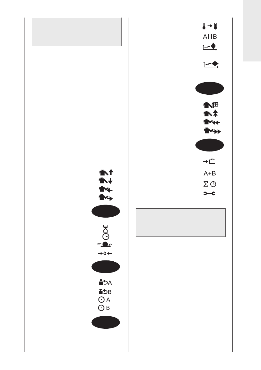
5.4 ARTROMOT®-S3
Comfort-Version
programmieren
Bei der ARTROMOT®-S3 Comfort-Version
sind zusätzliche Funktionen auf zwei
weiteren Programmierebenen wählbar.
Die Auswahl der Programmierebenen
erfolgt wie bei den Standardversionen.
Die Programmierebenen 1, 2, 3 und 6
entsprechen den Programmierebenen
1, 2, 3 und 4 der Standardversionen.
Sämtliche Sonderfunktionen sind in
der Standardeinstellung deaktiviert.
Folgende Behandlungswerte, Ein-
stellungen und Anzeigen können
über die Programmiereinheit (1)
eingegeben/abgerufen werden:
EBENE 1:
- Abduktion
- Adduktion
- Innenrotation
- Außenrotation
EBENE 4
- Aufwärmprogramm
- Isolationsprogramm
- Therapieverlaufsdokumentation
Abduktion/Adduktion
- Therapieverlaufsdokumentation
Innenrotation/Außenrotation
EBENE 5:
- Oszillation
- Dehnung Abduktion
- Dehnung Innenrotation
- Dehnung Außenrotation
EBENE 6:
- Transporteinstellung
- Betriebsart
Synchron/Asynchron
- Gesamttherapiezeit
- Service-Menü
Deutsch
MENU
MENU
EBENE 2:
- Pause
- Timer (Therapiezeit)
- Geschwindigkeit
- Neuer Patient
EBENE 3:
- Lastumkehr Motor A
- Lastumkehr Motor B
- Motor A Ein/Aus
- Motor B Ein/Aus
MENU
MENU
MENU
5.5 Informationen zu den
Programmen der
Comfort-Version
• Die gewünschte Programmierebene
wählen Sie durch mehrmaliges
Drücken der MENU-Taste aus.
• Die Behandlungsparameter wählen
Sie mit der jeweiligen Parametertaste
aus.
• Die Behandlungswerte verändern Sie
mit den + / – Tasten.
• Eine Funktion aktivieren/deaktivieren
Sie durch nochmaliges Drücken der
jeweiligen Parametertaste.
• Die vorgenommenen Einstellungen
speichern Sie durch Drücken der
STOP-Taste.
Sämtliche Sonderfunktionen sind in
der Standardeinstellung deaktiviert.
25
Page 26
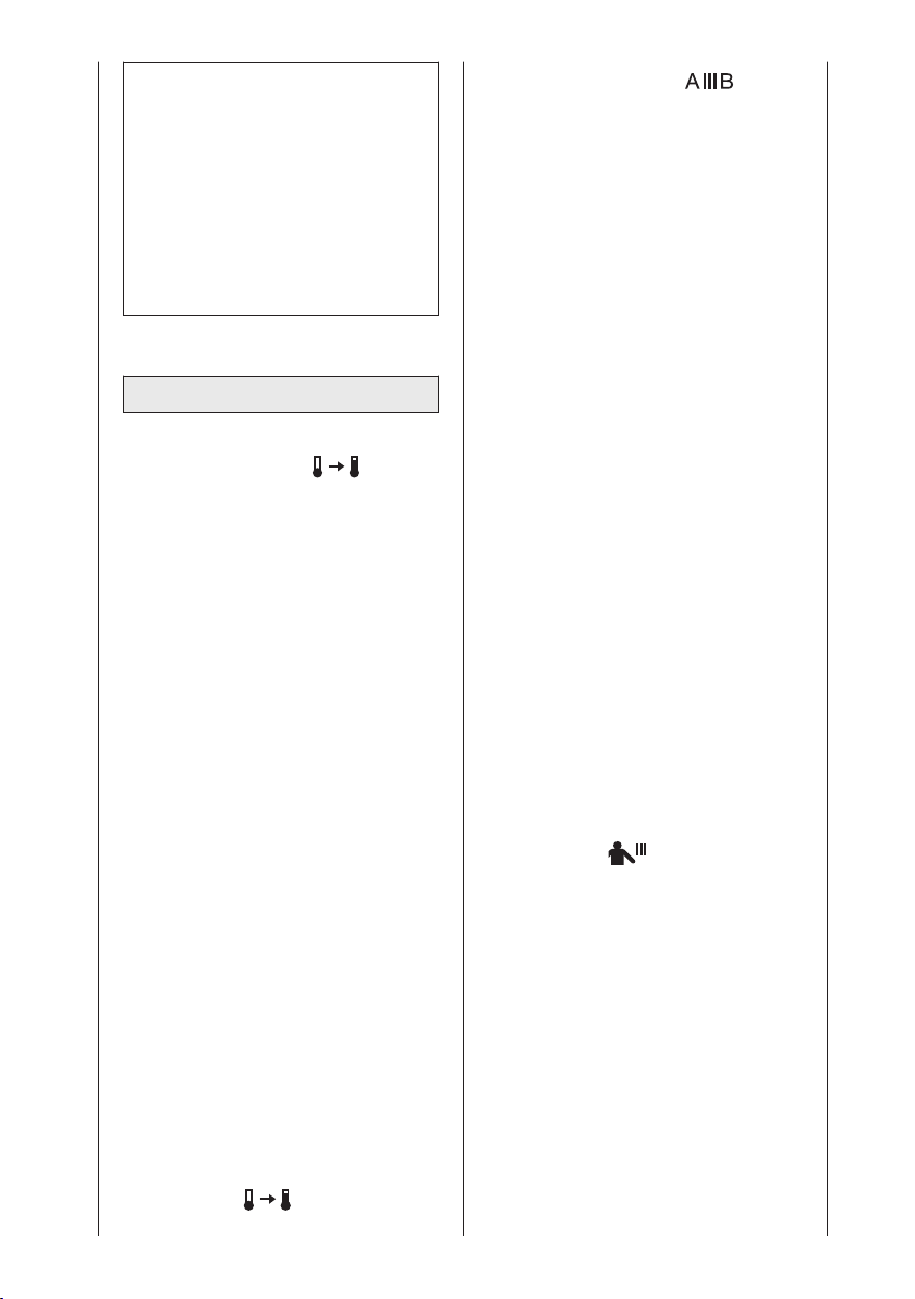
Hinweis!
EBENE 1: Entspricht Ebene 1
Stadardmodell (Siehe: 5.3)
EBENE 2: Entspricht Ebene 2
Standardmodell (Siehe: 5.3)
EBENE 3: Entspricht Ebene 3
Standardmodell (Siehe: 5.3)
EBENE 6: Entspricht Ebene 4
Standardmodell (Siehe: 5.3)
EBENE 4:
■ Aufwärmprogramm
Das Aufwärmprogramm ermöglicht
es, den Patienten langsam an die
eingestellten Grenzwerte für
Adduktion/Abduktion und
Innenrotation/Außenrotation heranzuführen.
Nach dem Aktivieren des Aufwärmprogramms bewegt sich die Schiene
zwischen den maximalen Adduktions- und Innenrotationswert und dem
Mittelwert des programmierten
Bewegungsausmaßes
(Adduktion/Innenrotation und Abduktion/Außenrotation).
Mit jedem Bewegungszyklus wird das
Bewegungsausmaß in Richtung der
Abduktion/Außenrotation um jeweils
3° erweitert, bis die eingestellten
Maximalwerte für Abduktion/Außenrotation erreicht sind.
Die Adduktions- und Innenrotationswerte werden bei jedem Zyklus
angefahren. Nach Erreichen der
Maximalwerte für Abduktion und
Außenrotation wechselt die Schiene
in den Normalbetrieb.
Ist eine Therapiezeit aktiviert, beginnt
die Therapie nach Ablauf der Therapiezeit und erneutem Starten des
Gerätes wieder mit dem Aufwärmprogramm.
Das Display zeigt im Aufwärmmodus
der Schiene im linken oberen Feld
das Symbol an.
Standardeinstellung: deaktiviert
■ Isolationsprogramm
Bei dieser Sonderfunktion sind beide
Motoren eingeschaltet, führen jedoch
nie gleichzeitig Bewegungen durch.
Der Ablauf der Sonderfunktion ist
wie folgt:
• Zuerst fährt Motor A für 10 Zyklen
die programmierten Maximalwerte
für Adduktion und Abduktion an,
bevor er stoppt. Motor B ist
währenddessen deaktiviert
(Anzeige Motor B: OFF)
• Anschließend fährt Motor B für
10 Zyklen die programmierten
Maximalwerte für Innenrotation
und Außenrotation an, bevor auch
er stoppt und der gesamte Zyklus
wiedermit Motor A beginnt. Während Motor B in Betrieb ist, ist
Motor A deaktiviert (Anzeige Motor
A: OFF)
• Die Stopp-Position am Ende des
jeweils zehnten Zyklus (sowohl für
die Adduktion/Abduktion, als auch
für die Innenrotation/Außenrotation)
kann in 25-%-Schritten von
0% - 100% des jeweils programmierten maximalen Bewegungsausmaßes gewählt werden.
• Die Schritte 1 und 2 können, je
nach Bedarf, beliebig oft wiederholt
werden. Die Behandlung wird durch
Drücken der Taste STOP, bzw.
nach Ablauf der programmierten
Therapiedauer beendet.
Das Display zeigt im Aufwärmmodus
der Schiene im linken oberen Feld
das Symbol an.
Standardeinstellung: deaktiviert
Die Sonderfunktion programmieren
Sie wie folgt:
• Wählen Sie in der Menüebene 4 mit
der Parametertaste die Sonderfunktion an. Auf dem Display erscheinen:
− das Symbol für die Sonderfunktion
− die Information über den Aktivierungszustand (Kreis mit/ohne
Häkchen) der Funktion
− zwei Kästchen mit der aktuell
eingestellten Prozentzahl für die
Stoppposition von Motor A und
Motor B.
− ein Häkchen im Markierungskreis.
26
Page 27
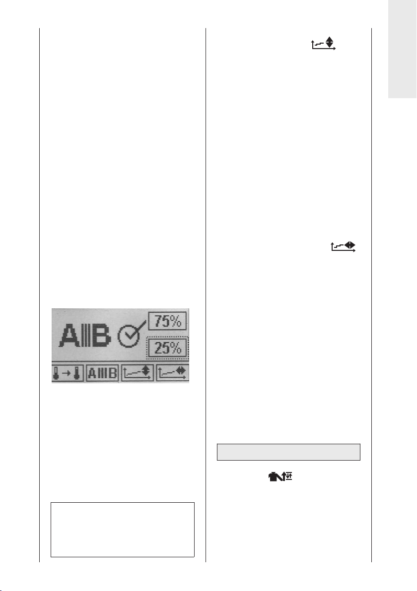
• Zum Aktivieren der Funktion drücken
Sie Taste „+“, zum Deaktivieren der
die Taste „-“
Ein Aktivieren/Deaktivieren durch
erneutes Drücken der Parameter-
taste ist hier nicht möglich.
Bei aktivierter Funktion erscheint das
Häkchen im Kreis.
• Drücken Sie anschließend die Parametertaste des Isolationsprogramms.
Die Markierung wechselt auf das
obere Prozentfeld zur Eingabe der
Stoppposition von Motor A.
• Verändern Sie den Werte durch
Drücken der Tasten „+“ oder „-“.
Wählen Sie hier z. B. 75%.
• Betätigen Sie anschließend erneut
die Parametertaste. Die Markierung
wechselt automatisch auf das untere
Kästchen zur Einstellung der Stoppposition von Motor B.
• Verändern Sie den Werte durch
Drücken der Tasten „+“ oder „-“.
Wählen Sie hier z. B. 25%.
• Speichern Sie die Programmierung
durch Drücken der Taste STOP und
starten Sie die Behandlung durch
Drücken der Taste START.
Dies bedeutet:
10 Mal wird zunächst die Abduktion/Adduktion behandelt (Motor A). Motor B
steht bei 25% des programmierten
Bewegungsausmaßes von Innenrotation
und Außenrotation.
Anschließend wird 10 Mal die Innen-/Außenrotation behandelt (Motor B).
Motor A steht bei 75% des programmierten Bewegungsausmaßes von
Adduktion und Abduktion.
Hinweis!
Die Prozentsätze können nur bei
aktivierter Sonderfunktion (Häkchen
im Kreis) verändert werden.
■ Therapieverlaufsdokumentation
Adduktion/Abduktion
Diese Sonderfunktion ermöglicht
bei der ARTROMOT
®
-S3 Comfort
eine Wiedergabe der Dokumentation
des gesamten Therapieverlaufs.
Aufgezeichnet wird sowohl die Schienenlaufzeit als auch das jeweilige
Bewegungsausmaß innerhalb der
Laufzeit.
Die Ausgabe/Darstellung erfolgt graphisch in Form zweier Zeit-/Verlaufskurven in einem Koordinatensystem
(X-Achse = Bewegungsumfang / YAchse = Zeit), wobei die obere Kurve
den Verlauf der Bewegungsentwicklung in Richtung der Abduktion zeigt
und die untere Kurve den Verlauf in
Richtung der Adduktion.
■ Therapieverlaufsdokumentation
Innenrotation/Außenrotation
Diese Sonderfunktion ermöglicht bei
der ARTROMOT
®
-S3 Comfort eine
Wiedergabe der Dokumentation des
gesamten Therapieverlaufs.
Aufgezeichnet wird sowohl die
Schienenlaufzeit als auch das
jeweilige Bewegungsausmaß
innerhalb der Laufzeit.
Die Ausgabe/Darstellung erfolgt
graphisch in Form zweier Zeit/Verlaufskurven in einem Koordinatensystem (X-Achse = Bewegungsumfang / Y-Achse = Zeit), wobei die
obere Kurve den Verlauf der Bewegungsentwicklung in Richtung der
Außenrotation zeigt und die untere
Kurve den Verlauf in Richtung der
Innenrotation.
EBENE 5:
■ Oszillation
Die Sonderfunktion „Oszillation“
ermöglicht ein effektiveres Arbeiten
innerhalb der letzten 10 ° vor Erreichen der als Maximum eingestellten
Werte für Abduktion und Außenrotation.
Hierfür startet die Schiene in der
Einstiegsposition (Maximaler Adduktionswert, Mittelwert zwischen
27
Deutsch
Page 28
Innen- und Außenrotation). Zunächst
wird der als Maximum programmierte
Innenrotationswert angefahren.
Anschließend wird der als Maximum
programmierte Abduktionswert gemeinsam mit dem maximalen
Außenrotationswert - angefahren.
Nach Erreichen des programmierten
Abduktions-/Außenrotationswertes
fährt die Schiene 10 ° in Richtung
Adduktion/Innenrotation, um dann
wieder den maximalen Abduktions/Außenrotationswert anzufahren.
Die Bewegung innerhalb der letzten
10 ° wird insgesamt 5 Mal mit
niedriger Geschwindigkeit wiederholt.
Nach Abschluss dieses Bewegungszyklus fährt die Schiene erneut den
als Maximum programmierten
Adduktionswert – gemeinsam mit
dem als Maximum programmierten
Innenrotationswert - an, um anschließend einen neuen Zyklus mit 5
Wiederholungen innerhalb der letzten
10 ° der Abduktion/Außenrotation zu
starten.
Dieser Ablauf kann, je nach Bedarf,
beliebig oft wiederholt werden. Die
Behandlung wird durch Drücken der
Taste STOP, bzw. nach Ablauf der
programmierten Therapiedauer,
beendet.
Standardeinstellung: deaktiviert
■ Dehnung Abduktion
Die Sonderfunktion „Dehnung
Abduktion“ ermöglicht ein sanftes
Dehnen des Gelenkes in Richtung
des Armanhebens. Es wird ausschließlich die Abduktion behandelt,
Motor B wird automatisch ausgeschaltet, die Position des Motors B
ist nach Aktivierung der Sonderfunktion nicht mehr veränderbar.
Ausgehend von der Mittelposition
fährt die Schiene zunächst zum
programmierten Adduktions- und
danach zum programmierten
Abduktionswert.
Anschließend fährt die Schiene 5 °
zurück in Richtung Adduktion, dann
sehr langsam wieder zurück zum
programmierten Abduktionswert
(Anzeige ) und versucht anschlie-
ßend – noch langsamer – 5 ° darüber
hinaus zu erreichen (Anzeige ).
Falls der Widerstand gegen die
zusätzlichen 5 ° zu stark werden
sollte, wird automatisch die Lastumkehr aktiviert und die Schiene fährt in
die entgegengesetzte Richtung.
Dieser Dehnungszyklus wird 10 Mal
wiederholt. Anschließend fährt die
Schiene in den maximal programmierten Dorsalextensionswert, um
erneut mit einem Dehnungszyklus
Abduktion zu beginnen.
Dieser Ablauf kann – je nach Bedarf –
beliebig oft wiederholt werden. Die
Behandlung wird durch Drücken der
Taste STOP, bzw. nach Ablauf der
programmierten Therapiedauer, beendet.
Standardeinstellung: deaktiviert
Hinweis!
• Sollte beim Aktivieren dieser
Funktion eine Pause programmiert
sein, wird diese jedes Mal bei
Erreichen des maximalen Dehnungspunktes eingehalten.
• Wird die Funktion „Dehnung
Abduktion“ aktiviert, wird automatisch der Motor B deaktiviert. Eine
Bewegung findet ausschließlich im
Sinne der Adduktion / Abduktion
statt.
• Die Sonderfunktion „Dehnung
Abduktion“ kann nicht zeitgleich mit
einer weiteren Dehnfunktion aktiviert werden.
• Das Display zeigt im Betriebsmodus der Schiene im linken oberen
Feld das Symbol an.
■ Dehnung Innenrotation
Die Sonderfunktion „Dehnung
Innenrotation“ ermöglicht ein sanftes
Dehnen des Gelenkes nach innen.
Ausgehend von der Mittelposition
fährt die Schiene zunächst zum
programmierten Außenrotations- und
danach zum programmierten Innenrotationswert.
Anschließend fährt die Schiene 5 °
zurück in Richtung Außenrotation,
28
Page 29
dann sehr langsam wieder zurück
zum programmierten Innenrotationswert (Anzeige ) und versucht
anschließend – noch langsamer - 5 °
darüber hinaus zu erreichen
(Anzeige )
Falls der Widerstand gegen die zusätzlichen 5 ° zu stark werden sollte,
wird automatisch die Lastumkehr
aktiviert und die Schiene fährt in die
entgegengesetzte Richtung.
Dieser Dehnungszyklus wird 10 Mal
wiederholt.
Anschließend fährt die Schiene in den
maximal programmierten Außenrotationswert, um erneut mit einem Dehnungszyklus Inversion zu beginnen.
Dieser Ablauf kann – je nach Bedarf –
beliebig oft wiederholt werden. Die
Behandlung wird durch Drücken der
Taste STOP, bzw. nach Ablauf der
programmierten Therapiedauer,
beendet.
Standardeinstellung: deaktiviert
Hinweis!
• Sollte beim Aktivieren dieser
Funktion eine Pause programmiert
sein, wird diese jedes Mal bei
Erreichen des maximalen Dehnungspunktes eingehalten.
• Wird die Funktion „Dehnung
Innenrotation“ aktiviert, wird
automatisch der Motor A
deaktiviert. Eine Bewegung
findet ausschließlich im Sinne
der Innen-/Außenrotation statt.
• Die Sonderfunktion „Dehnung
Innenrotation“ kann nicht zeitgleich
mit einer weiteren Dehnfunktion
aktiviert werden.
• Das Display zeigt im Betriebsmodus
der Schiene im linken oberen Feld
das Symbol an.
■ Dehnung Außenrotation
Die Sonderfunktion „Dehnung Außenrotation“ ermöglicht ein sanftes
Dehnen des Gelenkes nach außen.
Ausgehend von der Mittelposition
fährt die Schiene zunächst zum
programmierten Innen- und danach
zum programmierten Außenrotationswert.
Anschließend fährt die Schiene 5 °
zurück in Richtung Innenrotation,
dann sehr langsam wieder zurück
zum programmierten Außenrotationswert (Anzeige ) und versucht
anschließend - noch langsamer - 5 °
darüber hinaus zu erreichen (Anzeige
)
Falls der Widerstand gegen die
zusätzlichen 5 ° zu stark werden
sollte, wird automatisch die Lastumkehr aktiviert und die Schiene fährt in
die entgegen gesetzte Richtung.
Dieser Dehnungszyklus wird 10 Mal
wiederholt.
Anschließend fährt die Schiene in
den maximal programmierten Innenrotationswert, um erneut mit einem
Dehnungszyklus Außenrotation zu
beginnen.
Dieser Ablauf kann - je nach Bedarf beliebig oft wiederholt werden. Die
Behandlung wird durch Drücken der
Taste STOP, bzw. nach Ablauf der
programmierten Therapiedauer,
beendet
Standardeinstellung: deaktiviert
Hinweis!
• Sollte beim Aktivieren dieser
Funktion eine Pause programmiert
sein, wird diese jedes Mal bei
Erreichen des maximalen
Dehnungspunktes eingehalten.
• Wird die Funktion „Dehnung Außenrotation“ aktiviert, wird automatisch
der Motor A deaktiviert. Eine Bewegung findet ausschließlich im Sinne
der Innen-/Außenrotation statt.
• Die Sonderfunktion „Dehnung
Außenrotation“ kann nicht zeitgleich
mit einer weiteren Dehnfunktion
aktiviert werden.
• Das Display zeigt im Betriebsmodus
der Schiene im linken oberen Feld
das Symbol an.
Zur Erinnerung:
Zum Speichern der eingestellten
Parameter drücken Sie die Taste STOP.
29
Deutsch
Page 30

5.6 Anwendungs-/
Programmierbeispiele
5.6.1 Isolierte
Adduktion/Abduktion
1. Nehmen Sie die mechanischen
Einstellungen auf die jeweiligen
Patientenmaße wie unter Punkt
4.2 beschrieben vor.
2. Betätigen Sie die MENU-Taste
der Programmiereinheit, um auf
die Ebene 1 (M1) zu gelangen.
3. Betätigen Sie die Parametertaste
Innenrotation oder Außenrotation und bringen Sie die
Schiene mittels der +/- Tasten in
die gewünschte Rotationsposition,
die während der isolierten Bewegung
im Sinne der Abduktion/Adduktion
beibehalten werden soll.
4. Stellen Sie anschließend das
gewünschte Bewegungsausmaß für
die Ad-/Abduktion ein, indem Sie
zunächst die Parametertaste
Adduktion betätigen und
mittels der
+/- Tasten die Werte einstellen.
5. Stellen Sie auf die gleiche Weise die
Abduktion ein.
Hinweis!
- Für die reine Adduktion/Abduktion
muss Motor B für die Rotation wie
unter den folgenden Punkten 6 bis 8
beschrieben ausgeschaltet werden.
- Nachdem Sie die Bewegungsausmaße programmiert haben, können
Sie weitere Programmoptionen
wie Pause, Geschwindigkeit etc.
programmieren.
6. Betätigen Sie die MENU-Taste der
Programmiereinheit mehrmals, um
auf die Ebene 3 (M3) zu gelangen.
7. Betätigen Sie die Parametertaste
Motor B Ein/Aus , um den
Parameter zu aktivieren.
8. Deaktivieren Sie Motor B, indem Sie
erneut die Parametertaste Motor B
Ein/Aus, oder die „–“ -Taste betätigen. Das Häkchen im Kreis neben
dem Symbol darf nicht mehr angezeigt sein.
9. Speichern Sie die vorgenommenen
Einstellungen mit der STOP-Taste,
bringen Sie die Schiene durch
betätigen der START-Taste in die
Startposition und starten Sie die
Therapie durch erneutes Drücken der
START-Taste.
5.6.2 Isolierte Innenrotation/Außenrotation
1. Nehmen Sie die mechanischen
Einstellungen auf die jeweiligen
Patientenmaße wie unter Punkt 4.2
beschrieben vor.
2. Betätigen Sie die MENU-Taste der
Programmiereinheit, um auf die
Ebene 1 (M1) zu gelangen.
3. Betätigen Sie die Parametertaste
Adduktion oder Abduktion
und bringen Sie die Schiene mittels
der +/- Tasten in die gewünschte
Position, die während der isolierten
Bewegung im Sinne der Innen-/Außenrotation beibehalten werden soll.
4. Stellen Sie anschließend das
gewünschte Bewegungsausmaß für
die Innen-/Außenrotation ein, indem
Sie zunächst die Parametertaste
Innenrotation betätigen und
mittels der +/- Tasten die Werte
einstellen
5. Stellen Sie auf die gleiche Weise die
Außenrotation ein.
Hinweis!
- Für die reine Rotationsbewegung
muss Motor A für die Adduktion/Abduktion wie unter den folgenden
Punkten 6 bis 8 beschrieben ausgeschaltet werden.
- Nachdem Sie die Bewegungsausmaße programmiert haben, können
Sie weitere Programmoptionen
wie Pause, Geschwindigkeit etc.
programmieren.
30
Page 31
6. Betätigen Sie die MENU-Taste der
Programmiereinheit mehrmals, um
auf die Ebene 3 (M3) zu gelangen.
7. Betätigen Sie die Parametertaste
Motor A Ein/Aus , um den
Parameter zu aktivieren.
8. Deaktivieren Sie Motor A, indem
Sie erneut die Parametertaste
Motor A Ein/Aus, oder die
„–“ -Taste betätigen. Das Häkchen
im Kreis neben dem Symbol darf
nicht mehr angezeigt sein.
9. Speichern Sie die vorgenommenen
Einstellungen mit der STOP-Taste,
bringen Sie die Schiene durch
betätigen der START-Taste in die
Startposition und starten Sie die
Therapie durch erneutes Drücken
der START-Taste.
5.6.3 Isolierte Elevation
(Flexion)
1. Stellen Sie zuerst eine Außenrotation
von 90° ein und deaktivieren Sie
Motor B wie folgt:
a. Betätigen Sie die MENU-Taste
der Programmiereinheit, um auf
die Ebene 1 (M1) zu gelangen.
b. Betätigen Sie die Parametertaste
Außenrotation und bringen
Sie die Schiene mittels der
+ / - Tasten in die gewünschte
Rotationsposition von 90°.
Hinweis!
- Für die reine Elevation muss Motor
B für die Rotation wie unter den
folgenden Punkten c bis e ausgeschaltet werden.
- Nachdem Sie die Bewegungsausmaße programmiert haben, können
Sie weitere Programmoptionen
wie Pause, Geschwindigkeit etc.
programmieren.
c. Betätigen Sie die MENU-Taste der
Programmiereinheit mehrmals, um
auf die Ebene 3 (M3) zu gelangen.
d. Betätigen Sie die Parametertaste
Motor B Ein/Aus , um den
Parameter zu aktivieren.
e. Deaktivieren Sie Motor B, indem
Sie erneut die Parametertaste
Motor B Ein/Aus, oder die
„–“-Taste betätigen. Das Häkchen
im Kreis neben dem Symbol darf
nicht mehr angezeigt sein.
f. Speichern Sie die Einstellung
durch Drücken der STOP-Taste.
2. Nehmen Sie anschließend die mechanischen Einstellungen auf die individuellen Patientenmaße wie folgt vor:
a. Stellen Sie die Ante- /Retroversion
mit Hilfe des Rastknopfes (12)
†
auf 90° ein.
b. Sichern und halten Sie das Bewe-
gungselement am Aufnahmerohr
für die Längenverstellung und
öffnen Sie die Klemmschraube (14)
zur Höheneinstellung
Sie anschließend die Höhe so ein,
dass die Drehpunkte von Motor A
und Schulter übereinstimmen.
c. Öffnen Sie nun den Klemmhebel
(18) zur Einstellung der Oberarmlänge
, die Klemmschraube (20)
Å
zur Einstellung des Ellenbogenwinkelsèund die Klemmschraube (28)
zur Einstellung der Neigung der
Unterarmauflage und bringen Sie
das Bewegungselement in eine für
den Patienten angenehme und für
die Therapie gewünschte Position.
Anschließend schließen Sie die
einzelnen Fixierungen wieder.
d. Öffnen Sie den Klemmhebel (26),
stellen Sie die Unterarmlänge
auf das Patientenmaß ein und
schließen den Klemmhebel wieder.
3. Programmieren Sie nun das
gewünschte Bewegungsausmaß der
Elevation wie folgt:
a. Betätigen Sie die MENU-Taste der
Programmiereinheit, um auf die
Ebene 1 (M1) zu gelangen.
b. Stellen Sie anschließend das
gewünschte Bewegungsausmaß
für die Ad-/Abduktion ein, indem
Sie zunächst die Parametertaste
Adduktion betätigen und
. Stellen
Œ
Deutsch
31
Page 32

mittels der +/- Tasten die Werte
einstellen.
c. Stellen Sie auf die gleiche Weise
die Abduktion ein.
Hinweis!
- Nachdem Sie die Bewegungsausmaße programmiert haben, können
Sie weitere Programmoptionen
wie Pause, Geschwindigkeit etc.
programmieren.
4. Speichern Sie die vorgenommenen
Einstellungen mit der STOP-Taste,
bringen Sie die Schiene durch
betätigen der START-Taste in die
Startposition und starten Sie die
Therapie durch erneutes Drücken der
START-Taste.
32
Page 33

6. Pflege, Wartung, Transport, Umbau
6.1 Pflege
Warnung!
Stromschlaggefahr – Ziehen Sie vor
jeder Reinigung den Netzstecker aus
der Steckdose.
Stromschlaggefahr, Beschädigung
des Gerätes – Es dürfen keine Flüssigkeiten in das Gehäuse oder in die
Programmiereinheit eindringen.
• Die ARTROMOT®-S3 kann einer
Wischdesinfektion unterzogen
werden und entspricht damit den
gehobenen Anforderungen an medizintechnische Geräte.
• Das Gehäuse und die abnehmbaren
Armauflageschalen können mit
gebräuchlichen Desinfektionsmitteln und milden Haushaltsreinigern
gesäubert werden.
• Wischen Sie die Bewegungsschiene
nur mit einem feuchten Tuch ab.
Vorsicht!
Beschädigung des Gerätes –
− Die verwendeten Kunststoffe sind
nicht beständig gegen Mineralsäuren, Ameisensäure, Phenole,
Kresole, Oxydationsmittel und
starke organische und anorganische Säuren mit einem pH-Wert
unter 4.
− Verwenden Sie bitte ausschließlich
farbloses Desinfektionsmittel, um
Materialverfärbungen zu vermeiden.
− Schützen Sie die Bewegungsschiene vor intensiver UV-Bestrahlung (Sonnenlicht) und offener
Flamme.
Deutsch
6.2 Wartung (Sicherungen
auswechseln)
Prüfung vor jeder Anwendung
Führen Sie vor jeder Anwendung eine
Sichtkontrolle des Gerätes auf mechanische Beschädigungen durch.
Stellen Sie Schäden oder Funktionsstörungen fest, so dass die Sicherheit von
Patient und Bedienendem nicht mehr
gewährleistet ist, dürfen Sie das Gerät
erst wieder nach der Instandsetzung in
Betrieb nehmen.
Technische Kontrollen
Nur regelmäßig gewartete Geräte sind
betriebssicher. Zur Erhaltung der
Funktions- und Betriebssicherheit
führen Sie mindestens einmal pro Jahr
Kontrollen an allen Bauteilen auf mögliche Schäden oder lose Verbindungen
durch.
Diese Kontrollen dürfen nur von Personen durchgeführt werden, die aufgrund
ihrer Ausbildung, ihrer Kenntnisse und
ihrer durch praktische Tätigkeit gewonnenen Erfahrungen solche Kontrollen
ordnungsgemäß durchführen können
und hinsichtlich dieser Kontrolltätigkeit
keinen Weisungen unterliegen. Beschädigte oder verschlissene Teile sind
sofort von autorisiertem Fachpersonal
durch Original-Ersatzteile auszutauschen.
Diese Kontrollen können im Rahmen
einer Service-Vereinbarung vom
ORMED -Kundendienst übernommen
werden, der auch gerne Auskunft über
weitere Möglichkeiten gibt.
Ansonsten benötigt das Gerät keine
regelmäßige Wartung.
33
Page 34
Sicherungen auswechseln
6.3 Transport
Warnung!
Patientengefährdung, Funktionsstörungen bzw. Beschädigung des
Gerätes
Das Wechseln der Sicherungen darf
nur von Fachkräften im Sinne der DIN
VDE 0105 oder IEC 60364 oder direkt
vergleichbaren Normen durchgeführt
werden (z. B. Medizintechniker,
Elektriker, Elektroniker).
Es dürfen nur Sicherungen des Typs
T1A verwendet werden.
• Schalten Sie vor dem Wechseln der
Sicherungen die ARTROMOT
aus und ziehen Sie den Netzstecker.
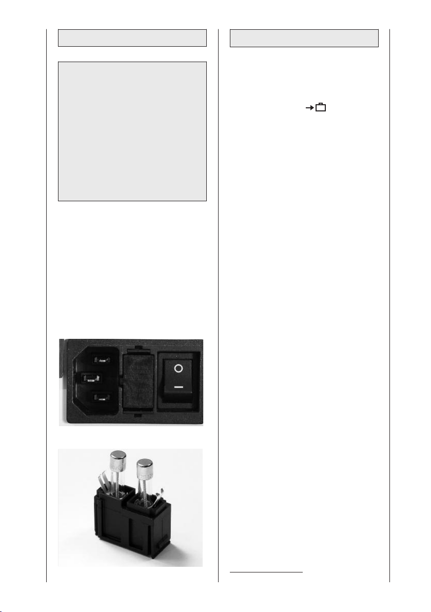
• Lösen Sie den Rastverschluss des
Sicherungshalters (8) zwischen
Netzschalter (7) und Netzstecker (6)
mit geeignetem Werkzeug (Abb. 1).
• Setzen Sie nach dem Austausch der
Sicherungen den Halter (Abb. 2)
wieder ein. Achten Sie darauf, dass
der Halter wieder korrekt einrastet.
Fig. 1
®
-S3
Zum Transport der ARTROMOT
®
-S3
müssen Sie folgende Einstellungen
vornehmen:
1. Aktivieren Sie die Funktion „Transporteinstellung“ im Menü
(siehe auch 5.3) und starten Sie die
ARTROMOT
2. Schalten Sie die ARTROMOT
®
- S3.
®
-S3
am Hauptschalter (7) aus.
3. Entfernen Sie die Geräteanschlussleitung (6), die Stecker für das
Bewegungselement und den Stecker für die Programmiereinheit (9).
4. Öffnen Sie Klemmschraube (14),
ziehen Sie die Armauflage (4) für den
gesunden Arm heraus.
5. Halten Sie das Bewegungselement
am Aufnahmerohr (17) fest, öffnen
Sie die Klemmschraube (14) und
ziehen Sie das Bewegungselement
heraus.
6. Stellen Sie Ante-/Retroversion
jeweils auf 0° (Rastknopf 12).
7. Öffnen Sie die Klemmschraube zur
Tiefeneinstellung der Kopfstütze (30)
und entfernen Sie die Kopfstütze
8. Öffnen Sie die Klemmschraube zur
Höheneinstellung der Schulterfixierung (31) und entfernen Sie diese
9. Öffnen Sie die Klemmschraube zur
Höheneinstellung der Patientenfixierung (32) und entfernen Sie diese
10. Öffnen Sie die Klemmschraube zur
Verstellung der Rückenlehne (10),
klappen Sie die Rückenlehne ganz
nach vorn, bis sie flach auf der
Sitzfläche liegt und schließen Sie die
Schraube wieder.
11. Entfernen Sie die beiden Sicherungssplinte (34). Ziehen Sie die
Stuhlbeine seitlich heraus, stecken
Sie diese seitenverkehrt wieder auf
und bringen Sie die Sicherungssplinte wieder an.
1
.
1
.
1
.
Fig. 2
1
Gilt nur für ARTROMOT®-S3 comfort
34
Page 35
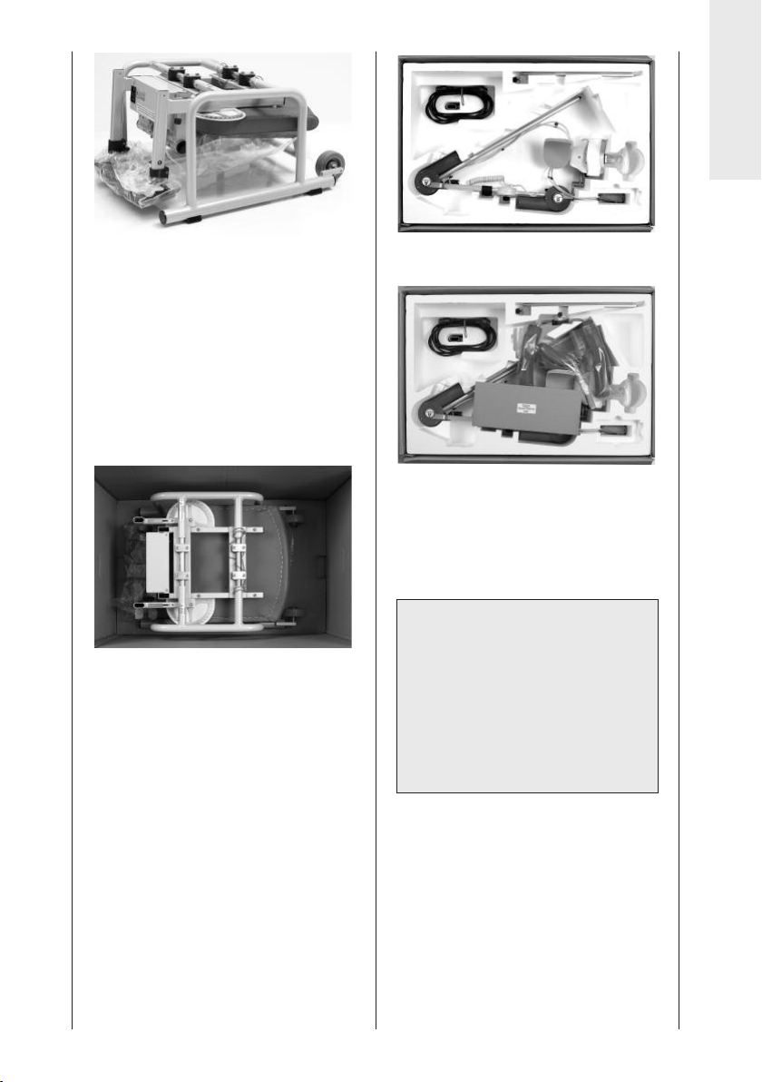
12. Zum Transport darf nur die Originalverpackung verwendet werden. Die
Firma Ormed GmbH & Co. KG haftet
nicht für Transportschäden, bei
denen keine Originalverpackung
verwendet wurde.
13. Stellen Sie die ARTROMOT
mit den Stuhlbeinen voran – auf den
Boden des Kartons. Für die richtige
Positionierung sind Markierungen
am Kartonboden vorgegeben.
14. Legen Sie nun das beigefügte
Styroporteil über den Stuhl und
achten Sie hierbei auf die Aussparungen im Styropor.
15. Legen Sie die Programmiereinheit (1)
in die beigelegte Kartonage. Das
Bewegungselement, die Armauflage,
die Teile der Nacken- und Schulterfixierung sowie die Geräteanschlussleitung legen Sie bitte in den jeweils
vorgegebenen Ausschnitt des
Styroporteiles der Verpackung.
®
-S3 –
Deutsch
16. Schließen Sie nun den Karton.
Für den Aufbau nach dem Transport
gehen Sie bitte in umgekehrter Reihenfolge vor.
Warnung!
Stromschlaggefahr – Vor der Inbetriebnahme ist sicherzustellen, dass
die ARTROMOT®-S3 Zimmertemperatur angenommen hat. Wurde das
Gerät bei Minusgraden transportiert
muss es ca. 2 Stunden bei Zimmertemperatur gelagert werden, bis evtl.
vorhandenes Kondenswasser abgetrocknet ist.
35
Page 36
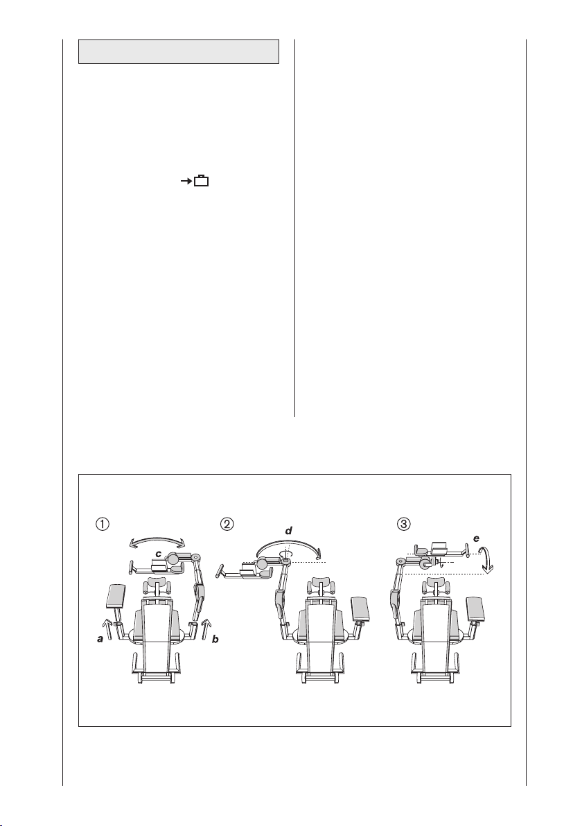
6.4 Umbau
Die ARTROMOT®-S3 ist für das linke
und das rechte Schultergelenk einsetzbar. Hierfür bedarf es jedoch eines
Umbaus. Dieser Umbau ist mit wenigen
Handgriffen möglich.
1. Aktivieren Sie die Funktion „Transporteinstellung“ im Menü
(siehe auch 5.3) und starten Sie die
ARTROMOT
2. Stellen Sie die Ante-/Retroversion
(Rastknopf 12) auf beiden Seiten auf
90° (siehe Umbauschema † ).
3. Öffnen Sie Klemmschraube (14),
ziehen Sie die Armauflage für den
gesunden Arm heraus und legen Sie
diese auf die Sitzfläche (siehe
Umbauschema † a).
4. Halten Sie das Bewegungselement
am Aufnahmerohr (17) fest und
öffnen Sie die Klemmschraube (14).
5. Ziehen Sie das Bewegungselement
heraus und schieben Sie es auf der
gegenüberliegenden Seite wieder
®
-S3.
ein. Schließen Sie die Klemmschraube (14) (siehe Umbauschema
† b, c)
6. Öffnen Sie die Klemmschraube (20)
und schwenken Sie die Unterarmauflage um 180°.
Ziehen Sie die Klemmschraube (20)
wieder fest (siehe Umbauschema Œ
d).
7. Halten Sie die Unterarmauflage fest
und öffnen Sie die Klemmschraube
(28).
8. Schwenken Sie die Unterarmauflage
um Motor B auf die andere Seite
und ziehen Sie die Klemmschraube
(28) wieder fest (siehe Umbauschema Å e).
9. Setzen Sie die Armauflage für den
gesunden Arm in das Aufnahmerohr
und ziehen sie die Klemmschraube
(14) fest
10. Stellen Sie die Ante-/Retroversion
auf der Seite des Bewegungselementes auf die gewünschte Gradzahl ein (in der Regel 0° bis maximal
40°, je nach Bedarf).
Umbauschema:
36
Page 37

7. Umwelthinweise
Das in dieser Gebrauchsanweisung
beschriebene Produkt darf nicht mit
dem gewöhnlichen, unsortierten Hausmüll entsorgt werden, sondern muss
separat behandelt werden. Bitte nehmen Sie Kontakt mit ORMED auf, um
Informationen hinsichtlich der Entsorgung Ihres Gerätes zu erhalten.
EMV IEC 60601-1(Elektromagnetische 2:2001
Verträglichkeit)
Umgebungsbedingungen
(Lagerung, Transport)
Umgebungstemperatur:
Relative
Luftfeuchtigkeit: 20 % bis 85 %
Luftdruck: 700 hPa bis
-24 ºC bis +60 ºC
1060 hPa
Deutsch
8. Technische Daten
Elektrischer Anschluss:
Nennstrom Motor: 2 A max.
Leistungsaufnahme 33 VA
Sicherungen: 2 x T1A
Schutzklasse: I
Anwendungsteil: Typ B
Maße (Transport):
Länge: 87,5 cm
Breite: 57,5 cm
Höhe: 58 cm
Verstellbereiche (min./max.):
Höheneinstellung: 35 – 71 cm
(Von Sitzfläche gemessen)
Oberarmlänge: 20 – 32 cm
Unterarmlänge: 29 – 46 cm
Sitzhöhe: 48 cm
Gewicht: 25 kg
Materialien: ABS, POM
MPG: Klasse 2a
Konform zu: IEC 60601-
100 – 240 V AC /
50 – 60 Hz
(Delrin 100),
PUR, PA, FR4,
Aluminium,
Edelstahl,
Messing
1:1990
+ A1:1993
+ A2: 1995
CSA No.
601.1-M90
UL 2601-1
Umgebungsbedingungen (Betrieb)
Umgebungstemperatur:
Relative
Luftfeuchtigkeit: 30 % bis 75 %,
Luftdruck: 700 hPa bis
Technische Änderungen vorbehalten.
(06/2007)
+10 ºC bis +40 ºC
1060 hPa
37
Page 38
9. IEC 60601-1-2:2001
Die ARTROMOT®-S3 unterliegt besonderen Vorsichtsmaßnahmen hinsichtlich
der elektromagnetischen Verträglichkeit
(EMV). Sie darf nur nach den in den
Begleitpapieren enthaltenen EMVRichtlinien installiert und in Betrieb
genommen werden.
Tragbare und mobile HF-Kommunikationseinrichtungen können die
ARTROMOT
Die ARTROMOT
®
-S3 beeinflussen.
®
-S3 darf nicht unmittelbar neben oder mit anderen Geräten
gestapelt angeordnet verwendet werden. Wenn der Betrieb nahe oder mit
anderen Geräten gestapelt erforderlich
ist, so muss die ARTROMOT®-S3
beobachtet werden, ob ihr bestimmungsgemäßer Betrieb in der benutzten Anordnung gewährleistet ist.
Stellen Sie Schäden oder Funktionsstö-
Patient und Bedienendem nicht mehr
gewährleistet ist, dürfen Sie das Gerät
erst wieder nach der Instandsetzung in
Betrieb nehmen.
Sollten Baugruppen oder Leitungen des
Gerätes ausgetauscht werden, so
dürfen nur originale Ersatzteile des
Herstellers verwendet werden damit die
EMV- Richtlinien auch nach einer
Instandsetzung weiterhin erfüllt bleiben.
Dies betrifft das Netzteil, die Leitungen
und deren Leitungslängen, die Antriebseinheit aus Motor und Ansteuerung, das
Handbedienteil mit Spiralkabel und
Steckverbinder.
Die nachfolgend verwendete Gerätebezeichnung ARTROMOT®-S3 beinhaltet alle Gerätevarianten wie
ARTROMOT®-S3 und ARTROMOT®-S3
comfort.
rungen fest, so dass die Sicherheit von
9.1 Elektromagnetische Aussendung
Leitlinien und Herstellererklärung – Elektromagnetische Aussendung
Die ARTROMOT®-S3 ist für den Betrieb in der unten angegebenen elektromagnetischen Umgebung bestimmt. Der Kunde oder der Anwender der ARTROMOT
in einer solchen Umgebung benutzt wird.
Aussendungs-Messungen Übereinstimmung Elektromagnetische Umgebung - Leitlinien
HF-Aussendungen nach
CISPR 11
HF-Aussendungen nach
CISPR 11
Oberschwingungen nach
IEC 61000-3-2
Spannungsschwankungen/
Flicker nach IEC 61000-3-3
Gruppe 1
Klasse B
Nicht anwendbar
Nicht anwendbar
Die ARTROMOT®-S3 verwendet HF-Energie
ausschließlich für interne Funktionen. Daher ist
die HF-Aussendung sehr gering und es ist
unwahrscheinlich, dass benachbarte elektronische Geräte gestört werden.
Die ARTROMOT®-S3 ist für den Gebrauch in
allen Einrichtungen einschließlich Wohnbereichen und solchen bestimmt, die unmittelbar an
ein öffentliches Versorgungsnetz angeschlossen sind, welches auch Gebäude versorgt, die
für Wohnzwecke genutzt werden.
®
-S3 sollte sicherstellen, dass sie
38
Page 39

9.2 Elektromagnetische Störfestigkeit
Leitlinien und Herstellererklärung – Elektromagnetische Störfestigkeit
ie ARTROMOT
D
Umgebung bestimmt. Der Kunde oder der Anwender der ARTROMOT
ass sie in einer solchen Umgebung benutzt wird.
d
Störfestigkeits-
rüfungen
p
ntladung statischer
E
Elektrizität (ESD) nach
EC 61000-4-2
I
®
S3 ist für den Betrieb in der unten angegebenen elektromagnetischen
-
IEC 60601-
rüfpegel
P
6 kV
±
Kontaktentladung
± 8 kV
Luftentladung
Übereinstim-
ungspegel
m
6 kV Kontak-
±
tentladung
± 8 kV Luftentladung
Elektromagnetische Umgebung
Leitlinien
-
ußböden sollten aus Holz oder
F
Beton bestehen oder mit Kera-
ikfliesen versehen sein. Wenn
m
der Fußboden mit synthetischem
Material versehen ist, muss die
relative Luftfeuchte mindestens
30 % betragen.
®
-S3 sollte sicherstellen,
Deutsch
Schnelle transiente
elektrische Störgrößen/Bursts nach IEC
61000-4-5
Stoßspannungen
(Surges) nach IEC
61000-4-5
Spannungseinbrüche,
Kurzzeitunterbrechungen und
Schwankungen der
Versorgungsspannung
nach
IEC 61000-4-11
Magnetfeld bei der
Versorgungsfrequenz
(50/60 Hz) nach IEC
61000-4-8
± 2 kV für
Netzleitungen
± 1 kV für
Eingangs- und
Ausgangsleitungen
± 1 kV Gegentaktspannung
± 2 kV Gleichtaktspannung
< 5 % U
T
(> 95 % Einbruch
) für ½
der U
T
Periode
40 % U
T
(60 % Einbruch
) für 5
der U
T
Perioden
70 % U
T
(30 % Einbruch
) für 25
der U
T
Perioden
< 5 % U
T
(> 95 % Einbruch
) für 5s
der U
T
± 2 kV für
Netzleitungen
± 1 kV für
Eingangs- und
Ausgangsleitungen
± 1 kV Gegentaktspannung
± 2 kV Gleichtaktspannung
< 5 % U
T
(> 95 % Einbruch
) für ½
der U
T
Periode
40 % U
T
(60 % Einbruch
) für 5
der U
T
Perioden
70 % U
T
(30 % Einbruch
) für 25
der U
T
Perioden
< 5 % U
T
(> 95 % Einbruch
) für 5s
der U
T
Die Qualität der Versorgungsspannung sollte der einer typischen Geschäfts- oder Krankenhausumgebung entsprechen.
Die Qualität der Versorgungsspannung sollte der einer typischen Geschäfts- oder Krankenhausumgebung entsprechen.
Die Qualität der Versorgungsspannung sollte der einer typischen Geschäfts- oder Krankenhausumgebung entsprechen.
Wenn der Anwender der
ARTROMOT
Funktion auch beim Auftreten von
®
-S3 fortgesetzte
Unterbrechungen der Energieversorgung fordert, wird empfohlen,
die ARTROMOT
unterbrechungsfreien Stromver-
®
-S3 aus einer
sorgung oder einer Batterie zu
speisen.
3 A/m 3 A/m Magnetfelder bei der Netzfre-
quenz sollten den typischen
Werten, wie sie in der Geschäftsund Krankenhausumgebung
vorzufinden sind, entsprechen.
ANMERKUNG: UTist die Netzwechselspannung vor Anwendung der Prüfpegel.
39
Page 40
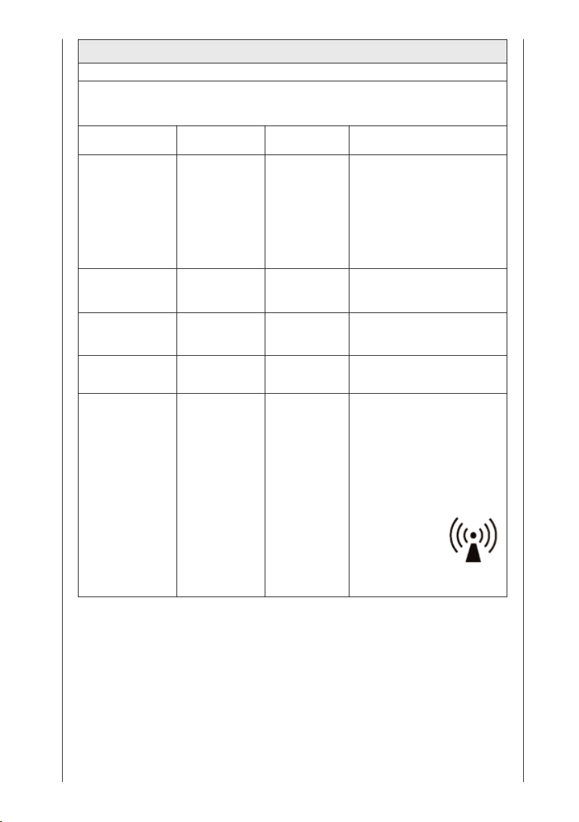
9.2 Elektromagnetische Störfestigkeit
Leitlinien und Herstellererklärung – Elektromagnetische Störfestigkeit
ie ARTROMOT
D
Umgebung bestimmt. Der Kunde oder der Anwender der ARTROMOT
ass sie in einer solchen Umgebung benutzt wird.
d
Störfestigkeitsprü-
ungen
f
Geleitete HFStörgrößen nach
IEC 61000-4-6
Gestrahlte HFStörgrößen nach
IEC 61000-4-3
®
S3 ist für den Betrieb in der unten angegebenen elektromagnetischen
-
IEC 60601-
rüfpegel
P
Übereinstim-
ungspegel
m
Elektromagnetische Umgebung -
eitlinien
L
ragbare und mobile Funkgeräte
T
werden in keinem geringeren
bstand zur ARTROMOT
A
einschließlich der Leitungen als
dem empfohlenen Schutzabstand
verwendet, der nach der für die
Sendefrequenz geeigneten
Gleichung berechnet wird.
Empfohlener Schutzabstand:
3 Veff
150 kHz bis
3 Veff
d = 1,2 öäP
80MHz
3 V/m
80 MHz bis 2,5
GHz
3 V/m
d = 1,2 öäP
80MHz bis 800 MHz
d = 1,2 öäP
800MHz bis 2,5 GHz
Mit P als der Nennleistung des
Senders in Watt (W) gemäß
Angaben des Senderherstellers
und d als dem empfohlenen
Schutzabstand in Metern (m).
Die Feldstärke stationärer Funksender ist bei allen Frequenzen
gemäß einer Untersuchung vor
Orta geringer als der Übereinstimmungspegelb.
In der Umgebung von
Geräten, die das
folgende Bildzeichen
tragen, sind
Störungen möglich.
®
-S3 sollte sicherstellen,
®
S3
-
ANMERKUNG 1: Bei 80 MHz und 800 MHz gilt der höhere Wert.
ANMERKUNG 2: Diese Leitlinien mögen nicht in allen Situationen zutreffen. Die Ausbreitung
elektromagnetischer Wellen wird durch Absorption und Reflektion von Gebäuden, Gegenständen
und Menschen beeinflusst.
a) Die Feldstärke stationärer Sender wie z. B. Basisstationen von Funktelefonen und mobilen
Landfunkdiensten, Amateurstationen, AM- und FM-Rundfunk- und Fernsehsendern, können
theoretisch nicht genau vorherbestimmt werden. Um die elektromagnetische Umgebung in Folge
von stationären HF-Sendern zu ermitteln, ist eine Untersuchung des Standortes zu empfehlen.
Wenn die ermittelte Feldstärke am Standort der ARTROMOT
Übereinstimmungspegel überschreitet, muss die ARTROMOT
®
-S3 den oben angegebenen
®
-S3 hinsichtlich ihres normalen
Betriebs an jedem Anwendungsort beobachtet werden. Wenn ungewöhnliche Leistungsmerkmale beobachtet werden, kann es notwendig sein, zusätzliche Maßnahmen zu ergreifen, wie z.
B. die Neuorientierung oder Umsetzung der ARTROMOT
®
-S3
b) Über den Frequenzbereich von 150 kHz bis 80 MHz ist die Feldstärke kleiner als 3 V/m.
40
Page 41
9.3 Empfohlene Schutzabstände
mpfohlene Schutzabstände zwischen tragbaren und mobilen HF-Kommunikationsgeräten und
E
der ARTROMOT
Die ARTROMOT®-S3 ist für den Betrieb in einer elektromagnetischen Umgebung bestimmt, in
der gestrahlte HF-Störgrößen kontrolliert werden. Der Kunde oder Anwender der
RTROMOT
A
Mindestanstände zwischen tragbaren und mobilen HF-Kommunikationseinrichtungen (Sendern)
nd der ARTROMOT
u
Kommunikationseinrichtung empfohlen, einhält.
Nennleistung des Senders
Für Sender, deren Nennleistung in obiger Tabelle nicht angegeben ist, kann der Abstand unter
Verwendung der Gleichung bestimmt werden, die zur jeweiligen Spalte gehört, wobei P die
Nennleistung des Senders in Watt (W) gemäß der Angabe des Senderherstellers ist.
ANMERKUNG 1: Zur Berechnung des empfohlenen Schutzabstandes von Sendern im Frequenzbereich von 80 MHz bis 2,5 GHz wurde ein zusätzlicher Faktor von 10/3 verwendet, um die
Wahrscheinlichkeit zu verringern, dass ein unbeabsichtigt in den Patientenbereich eingebrachtes
mobiles/tragbares Kommunikationsgerät zu einer Störung führt.
ANMERKUNG 2: Diese Leitlinien mögen nicht in allen Situationen zutreffen. Die Ausbreitung
elektromagnetischer Wellen wird durch Absorption und Reflektion von Gebäuden, Gegenständen
und Menschen beeinflusst.
®
-S3
®
S3 kann helfen, elektromagnetische Störungen dadurch zu verhindern, dass er
-
®
S3, wie unten entsprechend der maximalen Ausgangsleistung der
-
W
150 kHz bis 80 MHz
d = 1,2 öäP
Schutzabstand gemäß Sendefrequenz
80 MHz bis 800 MHz
m
d = 1,2 öäP
800 MHz bis 2,5 GHz
d = 1,2 öäP
0,01 0,12 0,12 0,23
0,1 0,38 0,38 0,73
1 1,2 1,2 2,3
10 3,8 3,8 7,3
100 12 12 23
Deutsch
10. Kontakte
Für Produktfragen und Service stehen
wir Ihnen gerne zur Verfügung.
■
Ormed international
Bitte setzen Sie sich mit Ihrem
örtlichen Händler in Verbindung oder
direkt mit der Hauptniederlassung
Deutschland.
■
Hauptniederlassung Deutschland
Ormed GmbH & Co. KG
Merzhauser Straße 112
D-79100 Freiburg
Tel. +49 761 45 66-01
Fax +49 761 45 66 55-01
■
Internet
www.ormed.de
e-mail: [email protected]
■
Gewährleistung:
2 Jahre (mechanische Teile)
2 Jahre (Elektronik)
■
Vertrieb:
Ormed GmbH & Co. KG
Merzhauser Straße 112
D-79100 Freiburg
41
Page 42
11. Technischer Service
11.1 Technische Hotline
Haben Sie technische Fragen?
Benötigen Sie den technischen
Service?
Telefon : +49-180-5-1 ormed de
+49-180-5-1 67 63 33
Fax : +49-180-5-3 ormed de
+49-180-5-3 67 63 33
11.2 Versand
Versenden Sie das Gerät nur in der
Originalverpackung, um Transportschäden zu vermeiden. Versandkartons
können bei ORMED bestellt werden.
Vor dem Verpacken der Schiene müssen Sie diese in die Transportstellung
fahren (siehe Kapitel 5 und 6).
11.3 Ersatzteile
Die aktuelle Ersatzteilliste entnehmen
Sie bitte dem Service Manual.
Bei Bestellungen von Ersatzteilen bitte
immer angeben:
- Position
- Beschreibung
- Artikelnummer
- Menge
- Seriennummer des Gerätes
Im Einzelfall bitte Mindermengenzuschläge für Ersatzteile beachten.
os. Beschreibung Art.-Nr. Menge
P
1. Patienten-Chipkarte 0.0034.048
. Patienten-Chipkarte
2
(Protokoll) 0.0037.035
3. Folienstift für
Patienten-Chipkarte 0.0031.006
Hinweis!
Reparaturen dürfen nur von autorisiertem Fachpersonal durchgeführt
werden.
ORMED GmbH & Co. KG bietet
Ihnen entsprechende Service-Schulungen an.
42
Page 43

12. Konformitätserklärung
Konformitätserklärung
Gemäß den Bestimmungen der EG- Richtlinie 93/42/EWG vom
14.06.1993 für Medizinprodukte, erklärt die Firma
ORMED GmbH & Co.KG
Merzhauser Straße 112
D-79100 Freiburg
dass die Produkte der Produktlinie
ARTROMOT
mit der Richtlinie 93/42/EWG vom 14.06.1993 Anhang II sowie den
grundlegenden Anforderungen des Anhang I übereinstimmen.
0297
Freiburg, den 13.06.2007
®
gemäß Anhang
_______________________________________
- Qualitätsmanagement Beauftragter QMB-
Deutsch
Anhang:
ARTROMOT
ARTROMOT®-S3
ARTROMOT®-S3 Comfort
ARTROMOT®-K1
ARTROMOT®-K2
ARTROMOT®-K2PRO
ARTROMOT®-K2PRO Chip
ARTROMOT®-K3
ARTROMOT®-K4
ARTROMOT®-SP2
ARTROMOT®-SP3
ARTROMOT®-E2
ARTROMOT®-E2compact
KONFO RM ITÄTS ER KLÄRU NG
®
-S2PRO
43
Page 44

Contents
Device description 3
Figures 252
Symbol Overview 249
1. How to use the CPM device 45
1.1 Fields of application 45
1.2 Therapy objectives 45
1.3 Indications 45
1.4 Contraindications 45
®
2. ARTROMOT
2.1 Description of the device components 46
2.2 Description of the programming unit 47
2.3 Explanation of symbols 50
2.4 Explanation of symbols (connections and nameplate) 51
3. Safety information 52
4. Device setup 55
4.1 Connecting the device, performance check 55
4.2 Adjusting the device to the patient 56
5. Setting the treatment values 58
5.1 General information on programming ARTROMOT
5.2 Programming ARTROMOT
5.3 Treatment value details – Standard model 60
5.4 Programming ARTROMOT
5.5 Protocol details – Comfort model 66
5.6 Examples of use/sample protocols 70
6. Care, Maintenance, Transport, Conversion 73
6.1 Care 73
6.2 Maintenance (fuse replacement) 73
6.3 Transport 74
6.4 Conversion 76
7. Environmental Protection Statement 77
8. Specifications 77
9. IEC 60601-1-2:2001 78
9.1 Electromagnetic emissions 78
9.2 Electromagnetic immunity 79
9.3 Recommended separation distances 81
10. Contact 81
11. Technical Service 82
11.1 Technical hotline 82
11.2 Shipment 82
11.3 Spare parts 82
12. Declaration of conformity 83
-S3 description 46
®
®
-S3 Standard 60
®
-S3 Comfort 65
-S3 58
44
Page 45
1. How to use the CPM device
1.1 Fields of application
ARTROMOT®-S3 is a motor-operated
Continuous Passive Motion (CPM)
device providing motion to the shoulder
joint.
Suitable for use in hospitals, clinics,
general practices and rental services, it
is an important supplement to medical
and therapeutic treatment.
1.2 Therapy objectives
CPM therapy with ARTROMOT
mainly used to prevent the negative
effects of immobilization, to allow
patients to regain painless mobility of
joints at an early stage and to promote
healing and achieve a positive functional result.
Other objectives of therapy include:
- improvement of joint metabolism
- prevention of joint stiffness (arthrofibrosis)
- promotion of the regeneration and
healing of cartilage and damaged
ligaments
- faster hematoma/fluid resorption
- improved lymph and blood circulation
- thrombosis and embolism prophylaxis
®
-S3 is
1.3 Indications
The CPM device is indicated in the
treatment of most injuries and postoperative conditions and diseases of the
shoulder joint.
Examples:
- joint distortion and contusion
- arthrotomy and arthroscopy procedures in combination with synovectomy, arthrolysis or other intra-articular
interventions
- all types of arthoplasty
- mobilization of joints in anesthetized
patients
- operative treatment of fractures,
pseudoarthrosis, if exercise-stable
- decompression surgery (acromioplasty)
- endoprosthetic implants
- soft tissue surgery in the armpit and
the shoulder girdle
- tumor surgery in the shoulder region
1.4 Contraindications
Do NOT use ARTROMOT
patients with:
- acute inflammatory processes in the
joints, unless on the order of a physician
- spastic paralysis
- unstable osteosynthesis
®
-S3 on
English
45
Page 46
2. ARTROMOT®-S3 description
The motorized CPM device supports
the following movements of the shoulder joint:
Adduction/abduction 0° - 30° - 175°
Internal/external 90° - 0° - 90°
rotation
Elevation (flexion) 0° - 30° - 175°
with elbow bent between 60° and 90°
Horizontal adduction/ 0° -120°
abduction
(manual adjustment only)
It can be reconfigured for use on either
side.
Note !
To allow the current position of the
CPM device to be clearly indicated,
the internal rotation values on the
display and throughout this document
are identified with "-".
These are some of the outstanding
ARTROMOT®-S3 features:
- anatomically correct setup
- physiological movements
- maximum possible ranges of motion
- programming unit for precise adjustment of patient-specific therapy
values
- chip card for storage of the programmed therapy parameters
- easy transport
Biocompatibility
Those parts of the ARTROMOT
®
-S3
device that come into contact with the
patient when the device is used as
intended, are designed to fulfil the
biocompatibility requirements of the
applicable standards.
2.1 Description of the device
components
Note:
Please fold out page 3!
1. Programming unit
2. Patient chip card
3. Compartment for storage of
programming unit
4. Armrest for healthy arm
5. Wheels
6. Connection for power cord
7. Power switch (ON/OFF)
8. Instrument fuse
9. Connection for motion element
10. Thumbscrew for adjustment of the
backrest angle
11. Folds down the backrest (transport
position)
12. Adjustment for horizontal adduction/abduction
13. Holding tube for height adjusment
14. Locking screw for height
adjustment
15. Insertion tube for height adjustment
16. Motor A
17. Holding tube for length adjustment
(upper arm)
18. Clamping lever for length adjustment (upper arm)
19. Insertion tube for length adjustment
(upper arm)
20. Locking screw for elbow range
21. Motor B
22. Elbow support
23. Forearm support
24. Strap for forearm restraint
25. Holding tube for length adjustment
(forearm)
26. Clamping lever for length adjustment (forearm)
27. Insertion tube for length adjustment
(forearm)
28. Locking screw for swivel
mechanism
29. Handle
30. Headrest adjustment
31. Height adjustment for shoulder
32. Height adjustment for shoulder
restraint
restraint
1
1
33. Ball joint for headrest
1
1
34. Locking pin
Subject to technical modifications
(06/2007)
1
Only with ARTROMOT®-S3 comfort
46
Page 47
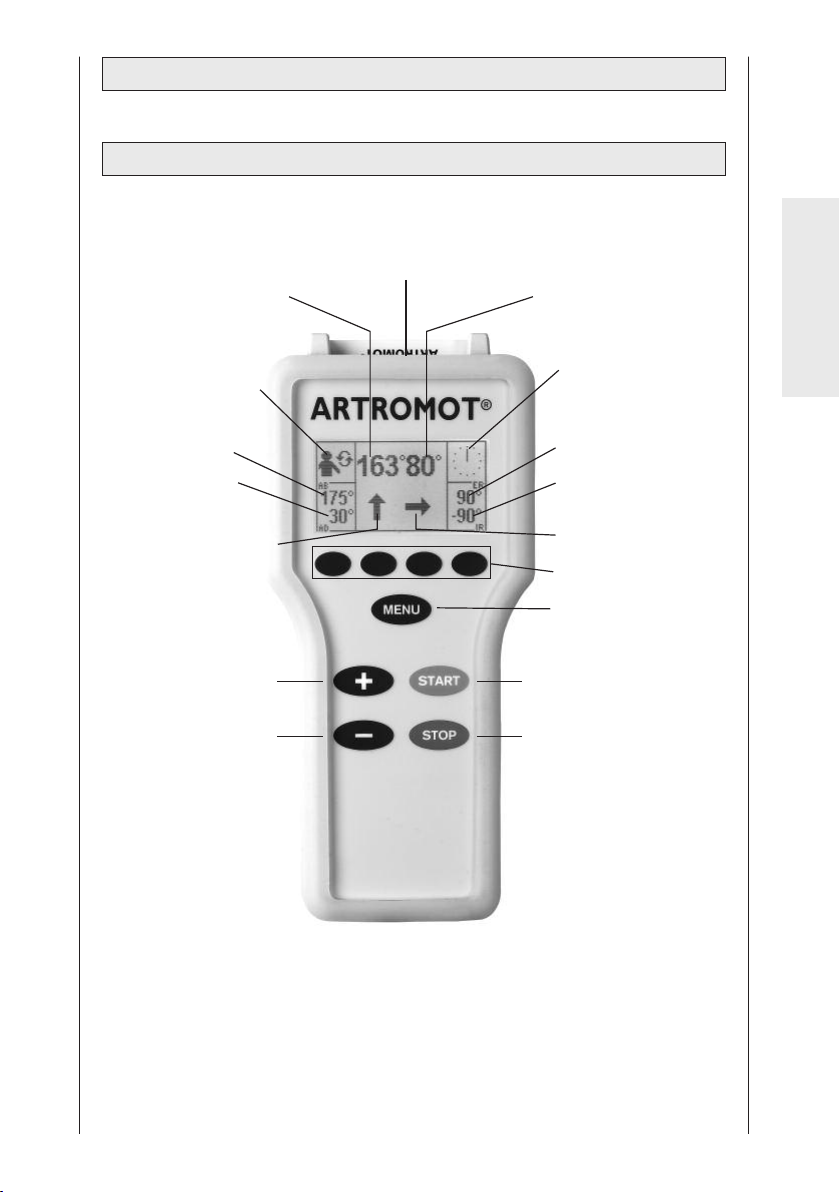
2.2 Description of the programming unit
2.2.1 Programming unit in normal mode
patient chip card
set angle of motor A
selected therapy
protocol
set angle of motor B
English
therapy timer
set abduction
value
set adduction
value
motor A - selected
direction of motion
+ (plus) key
- (minus) key
set external
rotation value
set internal
rotation value
motor B - selected
direction of motion
parameter keys
MENU key
START key
STOP key
47
Page 48
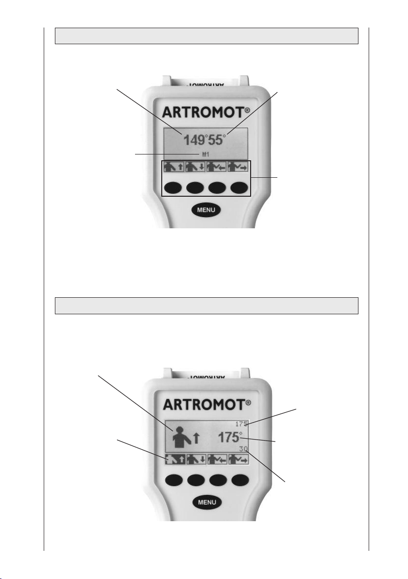
2.2.2 Programming unit in MENU selection mode
set carriage angle for
abduction/adduction
selected MENU level
2.2.3 Programming unit set to ROM programming
set carriage angle for
internal / external
rotation
selectable parameters
and the corresponding
selection keys
selected function
selected parameter
(here: abduction)
current maximum
value selected for
abduction or external
rotation
(here: abduction)
set carriage angle for
abduction/adduction
or internal/external
rotation
current maximum
value selected for
adduction or internal
rotation
(here: adduction)
48
Page 49
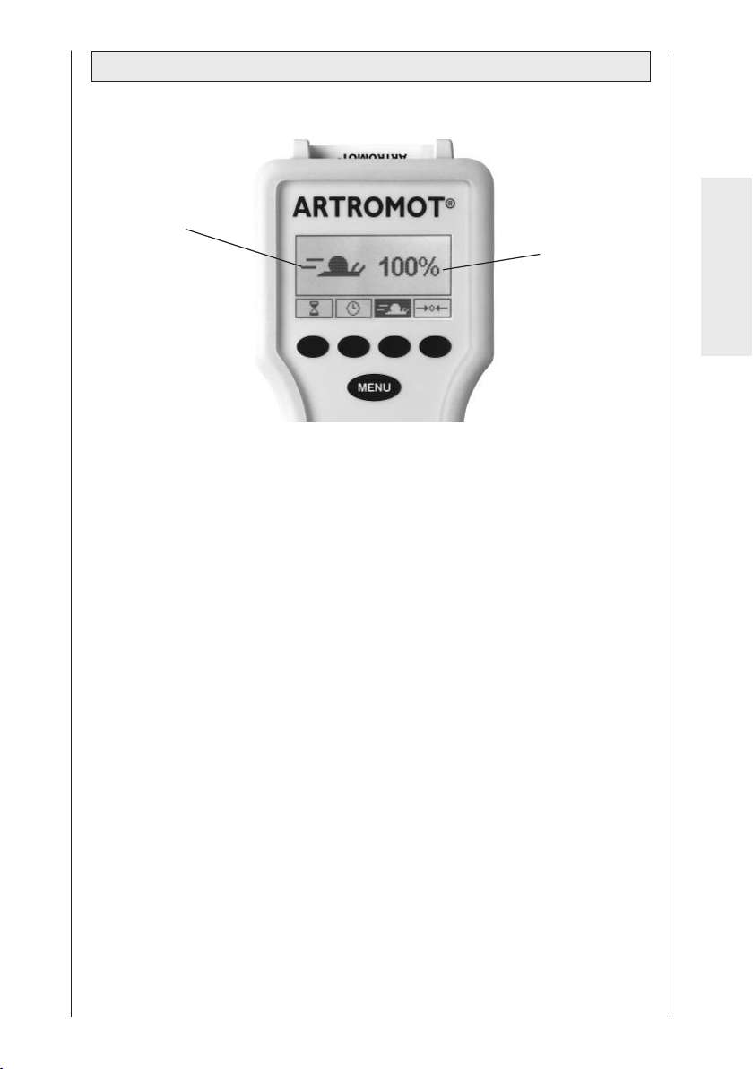
2.2.4 Programming unit in general programming mode
selected function
status of the selected
function (here: speed)
English
49
Page 50
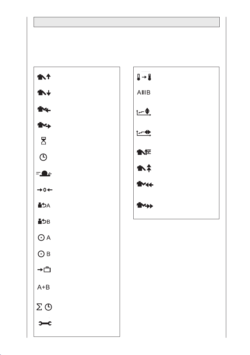
2.3 Explanation of symbols
Also refer to symbol overview on page 249.
Standard protocols: Comfort protocols:
Abduction
Adduction
Internal rotation
External rotation
Pause
Timer
Speed
New patient
Reverse on load - motor A
Reverse on load - motor B
Motor A ON/OFF
Warm-up protocol
Isolation program
Therapy documentation
Abduction/adduction
Therapy documentation
Internal/external rotation
Oscillation
Stretching in abduction
Stretching in internal
rotation
Stretching in external
rotation
Motor B ON/OFF
Transport setting
Synchronized/
non-synchronized mode
Total therapy time
Service menu
50
Page 51
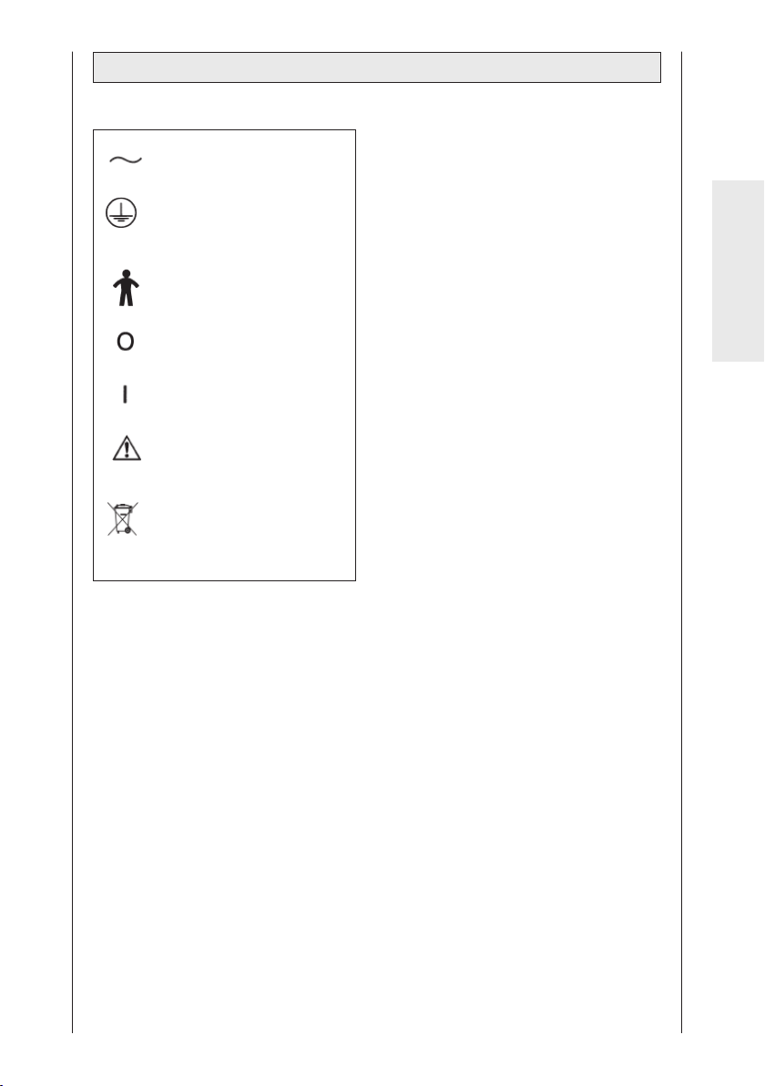
2.4 Explanation of symbols (connections and nameplate)
Alternating current
Protective earth
connection
Type B applied part
Power switch OFF
Power switch ON
Refer to accompanying
documents
Do not dispose of product
with unsorted household
or municipal waste.
English
51
Page 52
3. Safety information
Definitions
Read the safety statements before use
of the CPM device. The safety statements are classified as follows:
Danger!
This term indicates an imminent
hazard. If not avoided, this hazard will
result in death or serious injury.
Warning!
This term indicates a hazard. If not
avoided, this hazard can result in
death or serious injury.
Caution!
indicates a potential hazard. If not
avoided, this hazard can result in
minor personal injury and/or product/property damage.
Safety information
Danger!
Explosion hazard —
®
ARTROMOT
use in areas of medical locations
where an explosion hazard may occur.
An explosion hazard may result from
the use of flammable anesthetics, skin
cleansing agents and disinfectants.
-S3 is not designed for
Warning!
Patient hazard —
– Only authorized individuals are
allowed to operate the
ARTROMOT
are authorized after receiving
training in the operation of the
device and reading this operation
manual.
– Before using the device, the opera-
tor must ascertain that it is in
correct working order and operating
condition. In particular, the cables
and connectors must be checked
for signs of damage. Damaged parts
must be replaced immediately,
before use.
– Before therapy, a test run consis-
ting of several exercise cycles must
be completed, first without and then
with the patient. Check that all
setting screws are tightened.
– Stop therapy immediately, when you
have doubts about the device
settings and/or the therapy protocol.
– Ensure an anatomically correct
setup of the CPM device suitable
for the patient to be treated. For this
purpose, check the following
settings/positions (see numbers on
device):
1. Horizontal adduction/abduction
2. Height adjustment
3. Adjustment of upper arm length
4. Adjustment of elbow angle
5. Adjustment of forearm length
6. Adjustment of headrest
When the optional
patient restraint is used
7. Adjustment of
headrest and shoulder restraint
®
-S3 device. Individuals
1
1
1
Only with ARTROMOT®-S3 comfort
52
Page 53

– It is not permitted to change the
adjustment of 1 through 7 while a
patient is sitting in the CPM device.
– Movements must not cause any
pain or irritation.
– Patients must be fully conscious
while being instructed in the use of
the CPM device and during therapy.
– The choice of the therapy parame-
ters to program and of the therapy
protocols to use is restricted to
the responsible physician or
therapist.
It is the physician's or therapist's
decision whether or not to use the
CPM device on a specific patient
– The patient must be familiar with the
functions of the ARTROMOT
®
-S3
programming unit and the unit
must be within easy reach of the
patient, allowing him or her to stop
therapy, if needed. Patients unable
to operate the programming unit,
e. .g. paralytic patients, must never
be left unattended during therapy.
– Write the patient's name on the
patient chip card. The card should
only be used for this patient. If the
patient chip card is used for another
patient, be sure to delete the
previous patient's data from the
card first (see sections 4.1 and 5.3,
paragraph "New Patient").
Use original chip cards only.
– All accessories used with the
ARTROMOT
®
-S3 device must first
be approved by ORMED.
– Do not allow parts of the body or
any objects (such as blankets,
cushions or cables) to get caught in
the moving parts of the CPM
device.
Warning!
Shock hazard —
Strictly observe the following war-
nings. Failure to do so endangers the
lives of the patient, the user and other
persons involved.
– Before use allow the
ARTROMOT
temperature. If the device has been
transported at temperatures below
0 °C (32 °F), leave it to dry at room
temperature for about 2 hours, until
any condensation has disappeared.
– The ARTROMOT
operated in dry rooms.
– When disconnecting the device from
the power line, remove the plug
from the wall outlet first, before
disconnecting the cable from the
device.
– When connecting the device to
other equipment or when creating a
medical system, check that the sum
of leakage currents will not cause
any hazard. Please contact ORMED,
if you have questions in this matter.
– Do not use multiple portable socket
outlets (MPSO) to connect the
device to the power line.
ARTROMOT
ted to a properly installed wall
outlet with a non-fused earthed
wire. Before connecting the power
cord, it must be completely unrolled
and placed such that it will not get
caught in the moving parts of the
device.
– Before cleaning and service inter-
ventions, disconnect the device
from the power line by removing
the power cord from the wall outlet.
– Liquids must not be allowed to
enter the CPM device or the
programming unit. If liquids have
entered into the devices,
ARTROMOT
ately checked by a service technician, before it can be reused.
®
-S3 to reach room
®
-S3 must only be
®
-S3 must be connec-
®
-S3 must be immedi-
English
53
Page 54

Warning!
Equipment malfunction
– Magnetic and electrical fields are
capable of interfering with the
proper performance of the device.
For this reason make sure that all
external devices operated in the
vicinity of the CPM device comply
with the relevant EMC requirements.
X-ray equipment, MRI devices and
radio systems are possible sources
of interference as they may emit
higher levels of electromagnetic
radiation.
Keep the CPM device away from
these devices and verify its performance before use.
− Refer repair and maintenance to
authorized persons.
– Route all cables such that they will
not get caught in the moving parts
during operation and that they do
not present a stumbling hazard.
– Inspect the ARTROMOT
damage and loose connections at
least once a year.
®
-S3 for
Caution!
Equipment damage
– Check that the voltage and fre-
quency ratings of your local power
line are those indicated on the
nameplate.
– The seat withstands a maximum
continuous load of 150 kg
(330.7 lbs).
– Do not allow any objects (such as
blankets, cushions, or cables) to get
caught in the moving parts of the
CPM device.
– Do not expose the ARTROMOT
device to direct sunlight, because
some of the components may reach
inadmissibly high temperatures.
– Be aware that the connectors can
only be inserted in the correct
orientation and secure all connections with the locks.
®
-S3
Caution!
Preventing chafing and pressure sores
When your patient is adipose,
very tall or very short, be sure to
prevent chafing and pressure sores.
Patient hazard, damage to the carriage Do not use the carriage to
transport patients.
54
Page 55

4. Device setup
Note: For a better understanding of
each step, please fold out pages 3
and 252.
4.1 Connecting the device,
performance check
1. Connect the power cord to socket (6)
of the device and the mains plug to a
wall outlet with a non-fused earthed
wire (100 to 240 Volt, 50/60 Hz).
2. Turn the power switch (7) on.
3. Follow these steps to set the carriage
to the home position:
Initial adjustment for new patients
Write the patient's name down on the
back of the chip card. Insert the original
patient chip card (2) into the programming unit (1).
Press the MENU key on the programming unit three times to access programming level 3 (with each key press,
you advance one level).
Press the "new patient" parameter key
and select this function (a
check mark appears in the circle next to
the function).
Press the START key. The CPM device
automatically enters the home
position.
Setup with programmed chip card
Insert the original patient chip card (2)
into the programming unit (1).
Press the START key.
The device automatically enters the
starting position (maximum adduction,
halfway between internal / external
rotation).
Performance check
If the programming unit can be operated as described above and
ARTROMOT
position (for home position values, refer
to section 5.3), the device has passed
the performance check.
The device also runs performance
checks regularly during operation. This
is what happens, if a problem is identified:
– An audio signal sounds.
– The device switches off immediately.
– The message "ERROR" and an error
code (e.g. ERROR 5) appear on the
display.
In this situation, you may attempt to
restart the device by turning it briefly
off and on again with the power
switch. If the error message persists,
have the device inspected by a
Service technician, before using it
again.
®
-S3 enters the home
English
If it has been determined that the
ARTROMOT
perfectly, ask the patient to sit down on
the ARTROMOT®-S3 chair.
55
®
-S3 device operates
Page 56
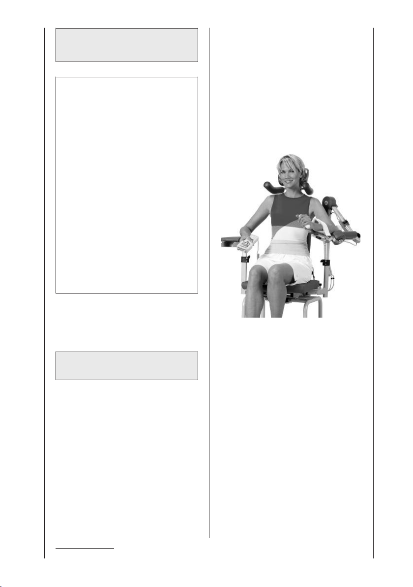
4.2 Adjusting the device to
the patient
Note!
For the following adjustments, the
patient's arm should not yet be
placed on the armrest. After you have
adjusted the device to the approximate patient measurements, the
patient can place his/her arm on the
armrest for a check of the setup and
for the fine adjustment.
The settings are numbered 1 through
5. For easy orientation, you will find
the same numbers on the CPM
device. Always set up the CPM device
in this order.
Write the settings down on the back
of the patient's chip card.
Before you adjust the der
ARTROMOT
may have to convert the device for
use on the left or right shoulder.
(see section 6.4 Conversion)
®
-S3 to the patient, you
• In the next step adjust the headrest
Height adjustment with locking screw
(32), headrest adjustment with locking
screw (30), fine adjustment with ball
joint (33).
• Use locking screw (31) to position the
shoulder restraint
1
approx. 1 cm
above the shoulders.
• Set the armrest for the healthy arm to
a height that allows the patient to sit
up straight (locking screw 14).
1
:
Before any treatment is possible, adjust
the device as follows:
Backrest, headrest, shoulder
restraint, armrest
Before you start setting up the device
for the exercise protocol, you must
adjust it to a position that is anatomically correct for the respective patient.
• Open thumbscrew (10) and adjust the
backrest to a position that is comfortable for the patient. (Fig. F)
1
Only with ARTROMOT®-S3 comfort
Anatomically correct adjustment
56
Page 57

Horizontal adduction/abduction
†
(Fig. A)
It is the purpose of the adjustment
procedures to accommodate the
patient in the most comfortable position
possible.
Note!
If the elbow angle is changed to a
flexion value of greater than or less
than 90°, the setting for the upper arm
length will have to be changed, too.
• Press on the indexing knob (12) and
make sure that it locks into place after
the adjustment.
Height adjustment (Fig. B)
Œ
Before opening locking screw (14), hold
the moving part of the CPM device by
grasping the holding tube for the length
adjustment (17), to prevent the part
from falling down.
• Adjust the height so that the axis of
motor A is level with the pivot of the
shoulder joint (see illustration on page
56). The pivot of motor A and the
pivot of the shoulder joint must be on
the same level.
• Tighten the locking screw.
Upper arm length (Fig. C)
Å
The device for adjustment of the upper
arm length is self-locking.
During adjustment, slightly lift motor B
and ensure that the insertion tube does
not wedge in the holding tube.
• Loosen clamping lever (18) and
slightly lift the motor during adjustment.
• Tighten the clamping lever.
Elbow angle (Fig. D)
è
In most cases an angle of 90° to 60° is
adjusted for elbow flexion.
• Loosen locking screw (20). To facili-
tate the adjustment, slightly lift motor
B.
• Complete the adjustment and tighten
the locking screw.
Forearm length (Fig. E)
ì
• Loosen clamping lever (26) and pull
out the handle until the forearm can
easily be accommodated between
elbow support and handle.
• Tighten the clamping lever.
Note!
The armrest inclination can be adjusted until optimally suited to the arm.
To do so, loosen the locking screw
(28) below the armrest. Adjust the
inclination and tighten the locking
screw.
Checking the setup, fine adjustment
• Place the patient's arm on the
armrest.
• Check adjustments 1 through 5 to
ensure that
– the pivot of motor A and the pivot
of the shoulder joint are on the
same level
– the axis of motor B, the center of
the elbow joint and the center of
the shoulder joint form a straight
line.
To adapt the armrest even better to
the patient, you can also adjust its
height and inclination. To do so,
loosen the locking screw (28) below
the armrest.
• Check that all locking screws are
tightened and all clamping levers
properly closed.
English
57
Page 58

5. Setting the treatment values
Warning!
Patient hazard
Before therapy, a test run consisting
of several exercise cycles must be
completed without the patient. Then
repeat the test run with the patient and
check that the movement does not
cause any pain.
Note: See also 2.2 and 2.3 as well as
page 249!
Note!
Programming is only possible when
the patient's chip card has been
inserted.
For information about therapy parameters and programming of special
functions, please refer to sections 5.1
to 5.5.
See section 5.6 for programming
examples.
Important!
The programming unit
ARTROMOT®-S3 "Graphics" can be
connected to all products of the
ARTROMOT®shoulder series with
serial numbers 3000 and higher.
It is possible to exchange chipcards
between the "Text" and "Graphics"
versions.
Please note:
1. If you use a "Graphics" programming unit with a formatted chipcard
of the "Text" version, please note
the following
- the selected language of the"Text"
version remains activated"; it is
irrelevant for the "Graphics"
version
- the reverse on load setting saved
in the "Text" version is automatically used for both motors
- the key lock is disabled.
2. If you use a "Text" programming
unit with a formatted chipcard of
the "Graphics" version, please note
the following
- the selected language automati-
cally changes to the default
setting: German
- the reverse on load setting saved
for motor A in the "Graphics"
version is automatically used for
both motors
- a key lock set in the "Graphics"
version will remain active,
because it is irrelevant for the
"Text" version.
5.1 General information on
programming
ARTROMOT®-S3
1. You activate the programming mode
by briefly pressing the MENU key on
the programming unit.
2. The treatment parameters and
functions are allocated to four
(Standard model) or six (Comfort
model) programming levels (four per
level). To be able to program a
parameter you will have to access
the corresponding programming
level. This is also done with the
MENU key. With each key press you
advance one level. The code M1, M2,
etc. that appears in the middle of the
display indicates the programming
level.
3. You activate the treatment parameters and functions with the four
parameter keys below the display.
The symbols above the four parameter keys indicate the assigned
parameters and functions.
58
Page 59
This is what happens when you press
one of the parameter keys to select a
parameter:
• The corresponding symbol appears
on the display in a larger format.
• The set value is displayed.
• The symbol above the parameter
key appears in reverse video.
4. With the + / - keys (plus/minus) you
change the displayed value. When
you press and hold the key, the value
will change at a faster rate.
Some of the (special) functions can
only be enabled and disabled. This is
done by pressing the corresponding
parameter key or with the + / - keys.
Active parameters are identified with
a check mark in the circle next to the
symbol.
5. Having programmed all parameters,
press the STOP key to save the
values.
6. Then press the START key:
ARTROMOT
®
-S3 checks the set
values, moves to the position halfway
between the set internal and external
rotation values as well as to the set
maximum adduction value and stops.
7. Press the START key again to start
therapy.
Next the carriage will move the
maximum internal rotation value in
the synchronized mode. The carriage will then simultaneously move
to the maximum external rotation
position and the maximum abduction
position and subsequently to the
maximum adduction position and the
maximum internal rotation position.
After reaching this position, the cycle
restarts: maximum abduction and
maximum external rotation.
After activation of the START key in
the non-synchronized mode the
motors will perform random movements, each motor reversing after
reaching the maximum values.
Note!
- Refer to sections 5.3 and 5.5 for a
description of the parameters.
- To view the set parameter values,
press the corresponding parameter
key. Before, however, you have to
press the STOP key and access the
correct menu level.
- To prevent accidental changes of the
parameter settings, lock the keys by
simultaneously pressing the + (plus)
and – (minus) keys.
Press both keys again to unlock.
- Selecting the "New Patient" function
will automatically delete the data on
the patient chip card. When you have
finished programming the unit and
press the STOP key, the settings will
automatically also be saved to the
patient chip card.
- Emergency stop function:
ARTROMOT
ately, when any of the keys is
pressed during therapy.
Patient treatment can be resumed
by pressing the START key. The
device will automatically change the
direction.
Patients with a programmed chip card
• First complete the mechanical adjustments.
• Then insert the chip card (the patient
is not yet positioned on the CPM
device).
• Press the START key: the device will
move to the starting position as
specified by the parameters stored on
the chip card and stops.
• Position the patient on the CPM
device and press the START key to
initiate therapy.
®
-S3 will stop immedi-
English
59
Page 60
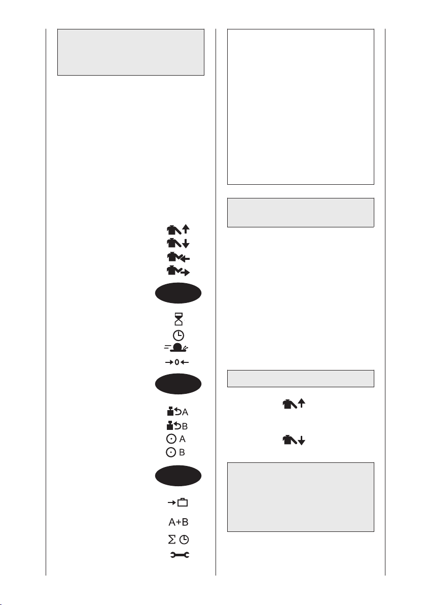
5.2 Programming
ARTROMOT®-S3
Standard
Different programming levels are
provided to program the
ARTROMOT®-S3 Standard models.
You change between levels by pressing
the MENU key repeatedly.
The display always indicates the
currently selected level.
The following treatment values,
settings and information can be
entered/viewed on the programming
unit (1):
LEVEL 1:
- Abduction
- Adduction
- Internal rotation
- External rotation
MENU
LEVEL 2:
- Pause
- Therapy timer
- Speed
- New patient
MENU
LEVEL 3:
- Reverse on load - motor A
- Reverse on load - motor B
- Motor A ON/OFF
- Motor B ON/OFF
Note!
• While you adjust the values, the
carriage will move to the set range.
This allows you to easily and
quickly determine the ROM where
the patient does not experience
pain.
• Special functions can be
programmed and retrieved with
ARTROMOT
(see sections 5.4 and 5.5).
• The angle entered last for the
respective direction of motion will
be saved in each case.
®
-S3 Comfort devices
5.3 Treatment value details –
Standard models
• To access the programming level you
need, press the MENU key repeatedly.
• The treatment parameters are selected
with the different parameter keys.
• To change the treatment values, press
the + / – keys.
• To enable/disable a function, press
the respective parameter key again.
• To save the entered values, press the
STOP key.
LEVEL 1:
■ Abduction
Maximum value: 175 degrees
■ Adduction
Maximum value: 30 degrees
LEVEL 4:
- Transport setting
- Synchronized/
non-synchronized mode
- Total therapy time
- Service menu
MENU
Caution!
Patient hazard
When using the shoulder restraint, be
sure not to program abduction values
greater than 80°.
60
Page 61
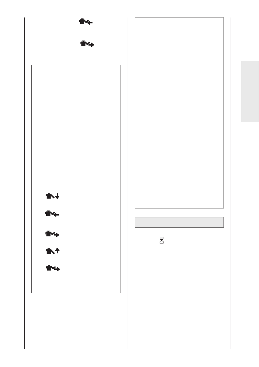
■ Internal rotation
Maximum value: - 90 degrees
■ External rotation
Maximum value: 90 degrees
Note!
• The programmed values and the
values (degrees) measured on the
patient may deviate slightly.
• To ensure a physiological motion,
the carriage simultaneously moves
to the following positions in the
synchronized mode:
- Maximum abduction value simulta-
neous with maximum external
rotation value
- Maximum adduction value simul-
taneous with maximum internal
rotation value
• To ensure that the movements you
program are physiological in nature,
we recommend to program the
carriage in the following order:
1. Maximum adduction value
2. Maximum internal rotation value
the carriage will first move to the
maximum adduction position and to
the position halfway between
internal and external rotation. Then
the carriage will stop, allowing the
patient to be positioned. When the
START key is pressed again (start
of therapy), the carriage will first
move to the maximum internal
rotation position. Motor A (abduction/adduction) stops during this
procedure. Once the maximum
internal rotation position has been
reached, both motors (A and B) will
simultaneously move to the maximum abduction and external
rotation position. After reaching this
position, the cycle restarts:
maximum adduction and maximum
internal rotation.
• The elevation movement (flexion) is
programmed by means of the
abduction/adduction values (for
mechanical adjustment instructions,
refer to section 5.6 "Examples of
use").
• Horizontal adduction/abduction is
adjusted manually. These are
possible settings:
Horizontal adduction: 120°
Horizontal abduction: 0°
English
3. External rotation
(to relieve the shoulder) = 0°
5. Maximum abduction value
6. Maximum external rotation value
• In the synchronized mode, after
activation of START
LEVEL 2:
■ Pauses
Pauses occur at each programmed
maximum value.
These are the two pause points:
- Maximum adduction value simultaneous with maximum internal
rotation value
- Maximum abduction value simultaneous with maximum external
rotation value
Pauses are adjustable in steps of 1
second between 0 and 30 seconds.
Default: no pause
61
Page 62
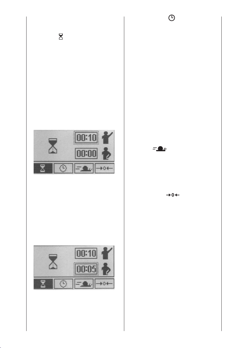
Follow these steps to program pauses:
• Access menu level 2, then press the
parameter key to select the special
function .
• The display indicates the symbol for
the special function and the selected
pause durations.
top: abduction/external rotation
pause
bottom: adduction/internal rotation
pause (see display image)
The pause duration for
abduction/external rotation appears
in a dotted frame.
• To change the abduction/external
rotation pause, press the "+" or "-"
key. Select a duration of 10 seconds,
for instance.
■ Therapy timer
Default setting is continuous
operation.
A clock symbol in the upper righthand corner of the display identifies
the continuous mode of operation.The clock indicates the elapsed
therapy time.
In the continuous mode, the device
must be stopped with the STOP key.
However, the therapy timer can be
set in steps of 1 minute to any
value between 1 and 300 minutes.
At the end of the therapy time, the
device automatically stops in the
starting position (maximum adduction
position / halfway between internal
and external rotation).
In this case, a circle replaces the
clock symbol. The circle fills as the
therapy time progresses.
■ Speed
The speed can be adjusted between
1 % and 100 % in steps of 1 %.
100 % is equivalent to 230°/minute
• Press the parameter key again
when done. The dotted frame
automatically moves to the line
below, indicating that the adduction/internal rotation pause can be
adjusted.
The parameter key is only used to
toggle between these two functions.
• To modify the value, press the "+"
(plus) or "-" (minus) key. Select a
duration of 5 seconds, for instance.
• Save the programmed values by
pressing the STOP key, then press
the START key to begin the treat-
ment.
Default: 100 %
■ New patient
With this function, the CPM device
will move to the home position.
Select the function and press the
START key:
– The carriage moves to the home
position.
– The programmed treatment
parameters are deleted.
– All values stored on the chip card
are deleted.
– The device stops halfway between
the abduction/adduction and
internal/external rotation position.
The "New patient" function (home
position) selects the following
settings:
62
Page 63
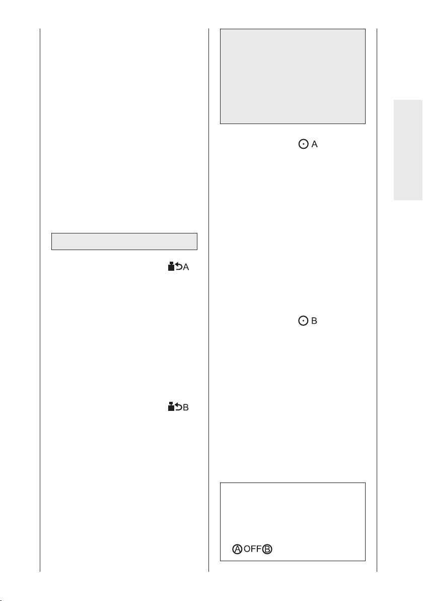
- Abduction: 41°
- Adduction: 39°
- Internal rotation: 1°
- External rotation: -1°
- Pauses: 0
- Timer: continuous operation
- Speed: 100 %
- Reverse on load - motor A: 25
- Reverse on load - motor B: 25
- Motor A: ON
- Motor B: ON
- Synchronized mode: ON
- Total therapy time: 0
- Special functions: disabled
LEVEL 3:
■ Reverse on load - motor A
(safety circuit)
The motors automatically switch to
opposite directions of movement
when the patient's resistance (load)
exceeds the set value.
Adjustable levels for reverse on load
feature: 1 - 25. At level 1, very low
resistance will cause the device to
reverse; at level 25, a high resistance
is required to initiate the reversal.
Default: level 25
■ Reverse on load - motor B
(safety circuit)
The motors automatically switch to
opposite directions of movement
when the patient's resistance (load)
exceeds the set value.
Adjustable levels for reverse on load
feature: 1 - 25. At level 1, very low
resistance will cause the device to
reverse; at level 25, a high resistance
is required to initiate the reversal.
Default: level 25
Caution!
Patient hazard
The reverse on load feature is a safety
measure to protect the patient in the
event of cramps, spasms, locked
joints and similar situations. The
manufacturer cannot be held liable for
misuse of this feature.
■ Motor A ON/OFF
To permit fully isolated movements,
the motors can individually be turned
on and off. Motor A effects adduction
and abduction, motor B effects
internal rotation and external rotation.
For an isolated internal / external
rotation movement, set motor A to
the programmed position (abduction/adduction), then turn the motor
off.
In normal mode the display indicates
the symbol "OFF" during therapy,
instead of the programmed adduction/abduction angles.
Default: motor A ON
■ Motor B ON/OFF
To permit fully isolated movements,
the motors can individually be turned
on and off. Motor A effects adduction
and abduction, motor B effects
internal rotation and external rotation.
For an isolated adduction/abduction
movement, set motor B to the
programmed position (internal /
external rotation), then turn the motor
off.
In normal mode the display indicates
the symbol "OFF" during therapy,
instead of the programmed internal/external rotation angles.
Default: motor B ON
Note!
• Please note that one motor (A or B)
must always be turned on. Otherwise the following symbol will be
displayed when you press START :
English
63
Page 64
LEVEL 4:
■ Transport setting
With this function, the carriage will
move to a position optimally suited
for packing the CPM device. Select
the function and press the START
key. The carriage moves to the
transport position. In the top lefthand corner of the display you will
see (also refer to section 6.3
Transport).
■ Synchronized/
non-synchronized mode
Motors A and B can run in synchronized or non-synchronized mode.
Synchronized:
Motors A and B perform a synchronized movement according to the
shoulder joint's physiological motion
pattern:
Starting from the initial position
(maximum adduction / halfway
between internal and external rotation position), the carriage will first
move to the maximum internal
rotation position. The carriage will
then simultaneously move to the
maximum abduction position and the
maximum external rotation position
and subsequently to the maximum
adduction position and the maximum
internal rotation position. After
reaching this position, the cycle
restarts: maximum abduction and
maximum external rotation.
During operation the synchronized
mode is indicated in the top left-hand
corner by the symbol .
Non-synchronized:
Both motors run independently of
each other within the selected ranges
of motion.
To enable the non-synchronized
mode, disable the synchronized
mode.
During operation the non-synchronized mode is indicated in the top
left-hand corner by the symbol
Caution!
Patient hazard
The synchronized operation is recom-
mended as a general rule. However,
medical and/or therapeutic indications
may call for the non-synchronized
mode. In the non-synchronized mode,
particular caution and attention on the
part of the physician/therapist is
required to rule out any risk for the
patient.
■ Total therapy time
Under menu item "total therapy time"
you can view each patient's total
therapy time (duration of all the
patient's therapy sessions).
To delete the stored therapy time:
Press and hold the parameter key
for 5 seconds or select the "New
patient" function.
■ Service menu
For service purposes only, refer to
Service Manual.
Reminder:
You save the selected parameter values
by pressing the STOP key.
Default: synchronized mode
enabled
64
Page 65
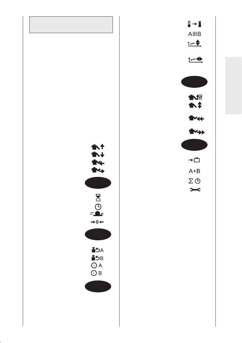
5.4 Programming
ARTROMOT®-S3 Comfort
ARTROMOT®-S3 devices of the Comfort
series offer two more programming
levels for additional functions.
The programming levels are selected in
the same way as on Standard models.
Programming levels 1, 2, 3 and 6 are
identical with programming levels 1 to 4
of the Standard models.
All special functions are disabled in
the standard models.
The following treatment values,
settings and information can be
entered/viewed on the programming
unit (1):
LEVEL 1:
- Abduction
- Adduction
- Internal rotation
- External rotation
MENU
LEVEL 2:
- Pause
- Therapy timer
- Speed
- New patient
LEVEL 4:
- Warm-up protocol
- Isolation program
- Therapy
documentation
Abduction/adduction
- Therapy
documentation
Internal/external rotation
LEVEL 5:
- Oscillation
- Stretching in abduction
- Stretching in internal
rotation
- Stretching in external
rotation
LEVEL 6:
- Transport setting
- Synchronized/
non-synchronized mode
- Total therapy time
- Service menu
MENU
English
MENU
LEVEL 3:
- Reverse on load - motor A
- Reverse on load - motor B
- Motor A ON/OFF
- Motor B ON/OFF
MENU
MENU
65
Page 66
5.5 Protocol details –
Comfort model
• To access the programming level you
need, press the MENU key repeatedly.
• The treatment parameters are
selected with the different parameter
keys.
• To change the treatment values, press
the + / – keys.
• To enable/disable a function, press
the respective parameter key again.
• To save the entered values, press the
STOP key.
All special functions are disabled in
the standard models.
Note!
LEVEL 1: equivalent to level 1
of the Standard model (see: 5.3)
LEVEL 2: equivalent to level 2 of
the Standard model (see: 5.3)
LEVEL 3: equivalent to level 3 of
the Standard model (see: 5.3)
LEVEL 6: equivalent to level 4 of
the Standard model (see: 5.3)
LEVEL 4:
■ Warm-up protocol
During warm-up, the patient will
slowly become used to the set
maximum values for
adduction/abduction and
internal/external rotation.
After activation of the warm-up
protocol the carriage moves between
the maximum adduction and abduction positions and the center position
of the programmed range of motion
(adduction/internal rotation and
abduction/external rotation).
With each cycle, 3° is added to the
abduction/external rotation range of
motion until the maximum abduc-
tion/external rotation positions are
reached.
The adduction and internal rotation
ranges are completed in each cycle.
Once the maximum abduction and
external rotation values have been
attained, the carriage switches to the
normal mode.
If a therapy time is activated, the
system restarts with the warm-up
protocol when the therapy time has
elapsed and the devices is started
again.
During warm-up, the display will
show the symbol in the upper,
left-hand corner.
Default: disabled
■ Isolation protocol
For this special function, both motors
are turned on, but they will never
move simultaneously.
These are the steps of the special
function:
• At first motor A moves to the
programmed maximum values for
adduction and abduction for ten
cycles, then it stops. In this phase,
motor B is disabled
(symbol for motor B: OFF)
• Then motor B will move to the
programmed maximum values for
internal and external rotation for 10
cycles and stops, after this the full
cycle will start over with motor A.
Motor A is disabled while motor B
is operating (symbol for motor A:
OFF)
• The stop position at the end of
each tenth cycle (for both adduction/abduction and internal/external
rotation) can be selected in steps of
25% between 0% and 100% of the
programmed maximum range of
motion.
• Steps 1 and 2 can be repeated as
often as needed. You can stop
treatment with the STOP key; after
the programmed therapy duration,
it will stop automatically.
During the isolation protocol, the
display will show the symbol in
the upper, left-hand corner.
Default: disabled
66
Page 67
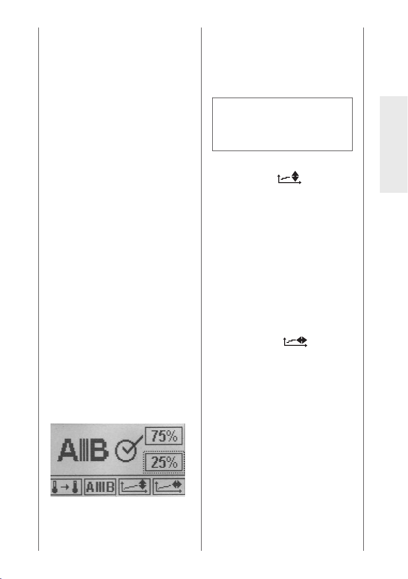
Follow these steps to program the
special function:
• Access menu level 4, then press the
parameter key to select the special
function. The display will indicate:
– the symbol representing the
special function
– the status of the special function
(circle with or without check mark)
– two boxes with the current
percentage of the stop positions
for motor A and B
– a check mark in a circle
• You activate the function with the "+"
key and deactivate it with the "-" key.
In this case it is not possible to
activate/deactive the function by
pressing the parameter key again. A
check mark in the circle identifies the
activated function.
• Next press the parameter key of the
isolation protocol. The dotted frame
moves to the upper percentage value,
allowing you to enter the stop position
for motor A.
• To modify the value, press the "+"
(plus) or "-" (minus) key. Select 75%,
for instance.
• Press the parameter key again when
done. The dotted frame automatically
moves to the lower value, allowing
you to adjust the stop position of
motor B.
• To modify the value, press the "+"
(plus) or "-" (minus) key. Select 25%,
for instance.
• Save the programmed values by
pressing the STOP key, then press
the START key to begin the treat-
ment.
range of motion for internal and external
rotation.
Subsequently, internal / external rotation is treated ten times (motor B).
Motor A is positioned at 75% of the
programmed range of motion for
adduction and abduction.
Note!
The percentage values can be
modified only when the special
function is enabled (check mark).
■ Therapy documentation adduction/abduction
This is a special function of
ARTROMOT
allows the entire therapy documentation to be represented. The carriage
run times as well as the range of
motion of the sessions are recorded.
The collected data are presented
graphically in the form of a coordinate
system (X-axis = range of motion /
Y-axis = time) where the upper curve
illustrates the trend of the abduction
movement and the lower curve the
trend of the adduction movement.
■ Therapy documentation internal /
external rotation
This is a special function of
ARTROMOT
allows the entire therapy documentation to be represented.
The carriage run times as well as the
range of motion of the sessions are
recorded.
®
-S3 Comfort which
®
-S3 Comfort which
English
This is what happens:
Abduction/adduction is treated ten
times first (motor A). Motor B is positioned at 25% of the programmed
The collected data are presented
graphically in the form of a coordinate system (X-axis = range of
motion / Y-axis = time) where the
upper curve illustrates the trend of
the external rotation movement and
the lower curve the trend of the
internal rotation movement.
67
Page 68
LEVEL 5:
■ Oscillation
The "oscillation" function permits a
more efficient therapy in the last 10°
before the maximum abduction and
adduction values are reached.
For this exercise, the carriage begins
at the starting position (maximum
adduction, halfway between internal
and external rotation). First of all the
carriage moves to the maximum
internal rotation position. Then it will
move to the maximum abduction
position, at the same time as the
maximum external rotation value.
When the abduction/external rotation
value has been reached, the carriage
reverses 10° toward
adduction/internal rotation and then
moves back again to the abduction/external rotation position.
The movement through the final 10°
is repeated five times at a slow
speed. At the end of the cycle, the
carriage will again move to the
maximum adduction position, at the
same time as the maximum internal
rotation value, and then starts
another cycle with five repetitions
through the last 10° of
abduction/external rotation.
This sequence can be repeated as
often as needed. You can stop
treatment with the STOP key; after
the programmed therapy duration, it
will stop automatically.
Default: disabled
■ Stretching in abduction
With the special "Stretching in
abduction" function the carriage
gently stretches the joint by lifting the
arm. Only the abduction movement is
treated here. Motor B is automatically
disabled. The position of motor B
cannot be changed once this special
function has been activated.
Starting at the middle position the
carriage will first move to the programmed adduction position and
then to the programmed abduction
position.
Subsequently the carriage reverses
5° towards adduction and then
moves very slowly back again to the
programmed abduction position
(display ). After that it attempts to
attain another 5°, moving even slower
than before (display ).
If a high resistance toward the
additional 5° is sensed, the reverse
on load function is automatically
activated and the carriage moves in
the opposite direction.
This stretch cycle is repeated ten
times. After that the carriage moves
to the programmed maximum adduction position and restarts the abduction stretch cycle.
This sequence can be repeated as
often as needed. You can stop
treatment with the STOP key; after
the programmed therapy duration, it
will stop automatically.
Default: disabled
Note!
• If a pause is programmed when you
enable the function, the carriage
will stop for the duration of the
pause each time the maximum
stretching value is attained.
• Enabling the stretching in abduction
function automatically disables
motor B. The only movement
performed is adduction / abduction.
• It is not possible to combine a
second stretching function with the
special function "stretching in
abduction".
• During operation, the display will
show the symbol in the
upper, left-hand
corner.
■ Stretching in internal rotation
With the special "Stretching in
internal rotation" function the carriage
gently stretches the joint towards the
inside.
Starting at the middle position the
carriage will first move to the programmed external rotation position
68
Page 69
and then to the programmed internal
rotation position.
Subsequently the carriage reverses
5° towards external rotation and then
moves very slowly back again to the
programmed internal rotation position
(display ). After that it attempts to
attain another 5°, moving even slower
than before (display ).
If a high resistance toward the
additional 5° is sensed, the reverse
on load function is automatically
activated and the carriage moves in
the opposite direction.
This stretch cycle is repeated ten
times.
After that the carriage moves to the
programmed maximum external
rotation position and restarts the
internal rotation stretch cycle.
This sequence can be repeated as
often as needed. You can stop
treatment with the STOP key; after
the programmed therapy duration, it
will stop automatically.
Default: disabled
Note!
• If a pause is programmed when you
enable the function, the carriage
will stop for the duration of the
pause each time the maximum
stretching value is attained.
• Enabling the stretching in internal
rotation function automatically
disables motor A.
The only movement performed is
internal / external rotation.
• It is not possible to combine a
second stretching function with the
special function "stretching in
internal rotation".
• During operation, the display will
show the symbol in the
upper, left-hand
corner.
■ Stretching in external rotation
With the special "Stretching in
external rotation" function the car-
riage gently stretches the joint
towards the outside.
Starting at the middle position the
carriage will first move to the programmed internal rotation position
and then to the programmed external
rotation position.
Subsequently the carriage reverses
5° towards internal rotation and then
moves very slowly back again to the
programmed external rotation position (display ). After that it
attempts to attain another 5°, moving
even slower than before (display
).
If a high resistance toward the
additional 5 ° is sensed, the reverse
on load function is automatically
activated and the carriage moves in
the opposite direction.
This stretch cycle is repeated ten
times.
After that the carriage moves to the
programmed maximum internal rotation position and restarts the
external stretch cycle.
This sequence can be repeated as
often as needed. You can stop
treatment with the STOP key; after
the programmed therapy duration, it
will stop automatically.
Default: disabled
Note!
• If a pause is programmed when you
enable the function, the carriage
will stop for the duration of the
pause each time the maximum
stretching value is attained.
• Enabling the stretching in external
rotation function automatically
disables motor A. The only movement performed is internal / external
rotation.
• It is not possible to combine a
second stretching function with the
special function "stretching in
external rotation".
• During operation, the display will
show the symbol in the
upper, left-hand
corner.
English
69
Page 70
Reminder:
You save the selected parameter values
by pressing the STOP key.
5.6 Examples of use/
sample protocols
5.6.1 Isolated
adduction/abduction
1. Complete the mechanical settings
and adjust the carriage to the patient
as described in section 4.2.
2. Press the MENU key on the programming unit to access level 1 (M1).
3. Press the parameter key for internal
rotation or external
rotation and press the +/keys to set the carriage to the
desired rotation position to be
maintained during the isolated
abduction/adduction movements.
4. Next set the desired range of motion
for adduction and abduction by first
pressing the parameter key for
adduction and set the values
with the +/- keys.
5. Set the abduction value in the same
way .
Note!
- For an exclusive
adduction/abduction protocol, motor
B for the rotation movement must be
turned off as described in steps 6 to
8 below.
- Having programmed the ranges of
motion, you can program additional
options, such as pause or speed.
6. Press the MENU key on the pro-
gramming unit to access level 3 (M3).
7. Press the Motor B ON/OFF parameter key to activate the parameter.
8. Deactivate motor B by pressing the
parameter key Motor B ON/OFF
again or the "–" (minus) key. The
check mark in the circle next to the
symbol must have disappeared.
9. Save the settings with the STOP key,
set the carriage to the starting
70
Page 71
position with the START key and
initiate therapy by pressing the
START key again.
5.6.3 Isolated elevation
(flexion)
5.6.2 Isolated internal rotation/external rotation
1. Complete the mechanical settings
and adjust the carriage to the patient
as described in section 4.2.
2. Press the MENU key on the programming unit to access level 1 (M1).
3. Press the parameter key for adduc-
tion or abduction and
press the +/- keys to set the carriage
to the desired position to be maintained during the isolated rotation
movements.
4. Next set the desired range of motion
for internal/external rotation by first
pressing the parameter key for
internal rotation and set the
values with the +/-keys.
5. Set the external rotation value in the
same way .
Note!
- For an exclusive rotation protocol,
motor A for adduction/abduction
must be turned off as described in
steps 6 to 8 below.
- Having programmed the ranges of
motion, you can program additional
options, such as pause or speed.
6. Press the MENU key on the pro-
gramming unit to access level 3 (M3).
7. Press the Motor A ON/OFF
parameter key to activate the parameter.
8. Deactivate motor A by pressing the
parameter key Motor A ON/OFF
again or the "–" (minus) key. The
check mark in the circle next to the
symbol must have disappeared.
9. Save the settings with the STOP key,
set the carriage to the starting
position with the START key and
initiate therapy by pressing the
START key again.
1. First adjust an angle of 90° for
external rotation and deactivate
motor B as follows:
a. Press the MENU key on the
programming unit to access
level 1 (M1).
b. Press the parameter key for
external rotation and move
the carriage to the rotation position of 90°, using the + / - keys.
Note!
- For an exclusive elevation protocol,
motor B for the rotation movement
must be turned off as described in
steps c to e below.
- Having programmed the ranges of
motion, you can program additional
options, such as pause or speed.
c. Press the MENU key on the
programming unit to access
level 3 (M3).
d. Press the Motor B ON/OFF
parameter key to activate the
parameter.
e. Deactivate motor B by pressing
the parameter key Motor B
ON/OFF again or the "–" (minus)
key. The check mark in the circle
next to the symbol must have
disappeared.
f. Save the entered values by press
the STOP key.
2. Complete the mechanical settings
and adjust the carriage to the patient
as follows:
a. Adjust an angle of 90° for horizon-
tal adduction/abduction
indexing knob (12).
b. Secure and hold the motion
element at the holding tube for
length adjustment and open the
locking screw (14) for height
adjustment
which the pivot points of motor A
71
. Select a height at
Œ
, using
†
English
Page 72
and the shoulder are at the same
level.
c. Now open clamping lever (18) for
adjustment of the upper arm
length
adjustment of the elbow angle
and locking screw (28) for adjustment of the forearm rest inclination
and set the motion element to a
position that is comfortable to the
patient and suitable for the therapy
session. When done, tighten all
screws and levers.
d. Open clamping lever (26), adjust
the forearm length
patient and close the clamping
lever.
3. In the next step, program the elevation range of motion as follows:
a. Press the MENU key on the
programming unit to access
level 1 (M1).
b. Next set the desired range of
motion for adduction and abduction by first pressing the parame-
ter key for adduction and
set the values with the +/- keys.
c. Set the abduction
the same way.
, locking screw (20) for
Å
to the
ì
è
value in
Note!
Having programmed the ranges of
motion, you can program additional
options, such as pause or speed.
4. Save the settings with the STOP key,
set the carriage to the starting
position with the START key and
initiate therapy by pressing the
START key again.
72
Page 73

6. Care, Maintenance, Transport, Conversion
6.1 Care
Warning!
Shock hazard – Unplug the device
from the power line before cleaning.
Shock hazard, equipment damage –
Liquids must not enter the device or
the programming unit.
• ARTROMOT®-S3 can be disinfected
by wiping down with a disinfectant.
Thus, it complies with the special
hygiene standards for medical
technical equipment.
• The enclosure and removable
armrest assemblies can be cleaned
with commonly used disinfectants
and mild household detergents.
• Only use a damp cloth to wipe the
CPM device down.
Caution!
Equipment damage –
– The plastic material used is not
resistant to mineral acids, formic
acid, phenols, cresols, oxidants and
strong organic or inorganic acids
with a pH value below 4.
– Use only clear disinfectants to
prevent discoloration of the device.
– Do not expose the CPM device to
strong ultraviolet radiation (sunlight)
and fire.
6.2 Maintenance
(fuse replacement)
Check before each use
Visually inspect the device for signs of
mechanical damage before each use.
If you detect damage or malfunctions
that may impair the safety of the patient
or of the operator, have the device
repaired before using it.
Technical inspections
For safety, the devices require regular
maintenance. To maintain the functional
and operational safety, check all components for damage and loose connections at least once a year.
These checks should be performed by
persons with adequate training and
experience. Damaged and worn parts
must immediately be replaced with
original spare parts by authorized staff.
The inspections can be carried out by
ORMED Technical Service within the
framework of a service agreement.
The device does not require additional regular maintenance.
English
73
Page 74
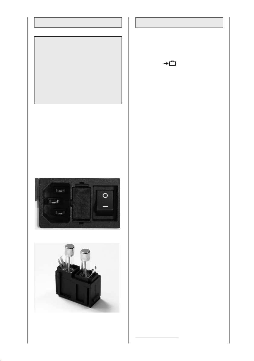
Fuse replacement
6.3 Transport
Warning!
Patient hazard, equipment malfunction and damage —
The replacement of fuses must be
referred to specialists as defined in
IEC 60364 or other applicable standards (e.g. biomedical technicians,
electricians, electronics installers).
Fuses used must be T1A fuses.
• Before replacing fuses, turn off the
ARTROMOT®-S3 and disconnect the
device from the power line.
• Use an appropriate tool to remove
the fuse holder (8) situated between
the power switch (7) and the power
connector (6) (Fig. 1).
• Replace the fuses and reinsert the
fuse holder (Fig. 2). Check that the
fuser holder locks properly into place.
Fig. 1
The following operating steps must be
completed before transporting the
ARTROMOT
®
-S3:
1. Activate the "transport setting"
function in the menu (see
also 5.3) and start the
ARTROMOT
2. Turn off the ARTROMOT
®
-S3.
®
-S3 power
switch (7).
3. Remove the power cord (6) and
disconnect the motion element and
the programming unit (9).
4. Open locking screw (14) and pull out
the armrest (4) for the healthy arm.
5. Grasping the holding tube (17) of the
motion element, open locking screw
(14) and pull out the motion element.
6. Set horizontal adduction/abduction
to 0° (indexing knob 12).
7. Open the locking screw for the
headrest adjustment (30) and
remove the headrest
1
.
8. Open the locking screw for the
shoulder restraint (31) and remove
9. Open the locking screw for the
height adjustment of the patient
restraint (32) and remove1.
10. Open the locking screw for adjustment of the backrest (10), fold the
backrest to the front all the way until
flat on the seat and tighten the
screw.
11. Remove the two locking pins (34).
Pull out the legs towards the sides,
reverse and reinsert. Then put the
locking pins back in place.
1
.
Fig. 2
1
Only with ARTROMOT®-S3 comfort
74
Page 75
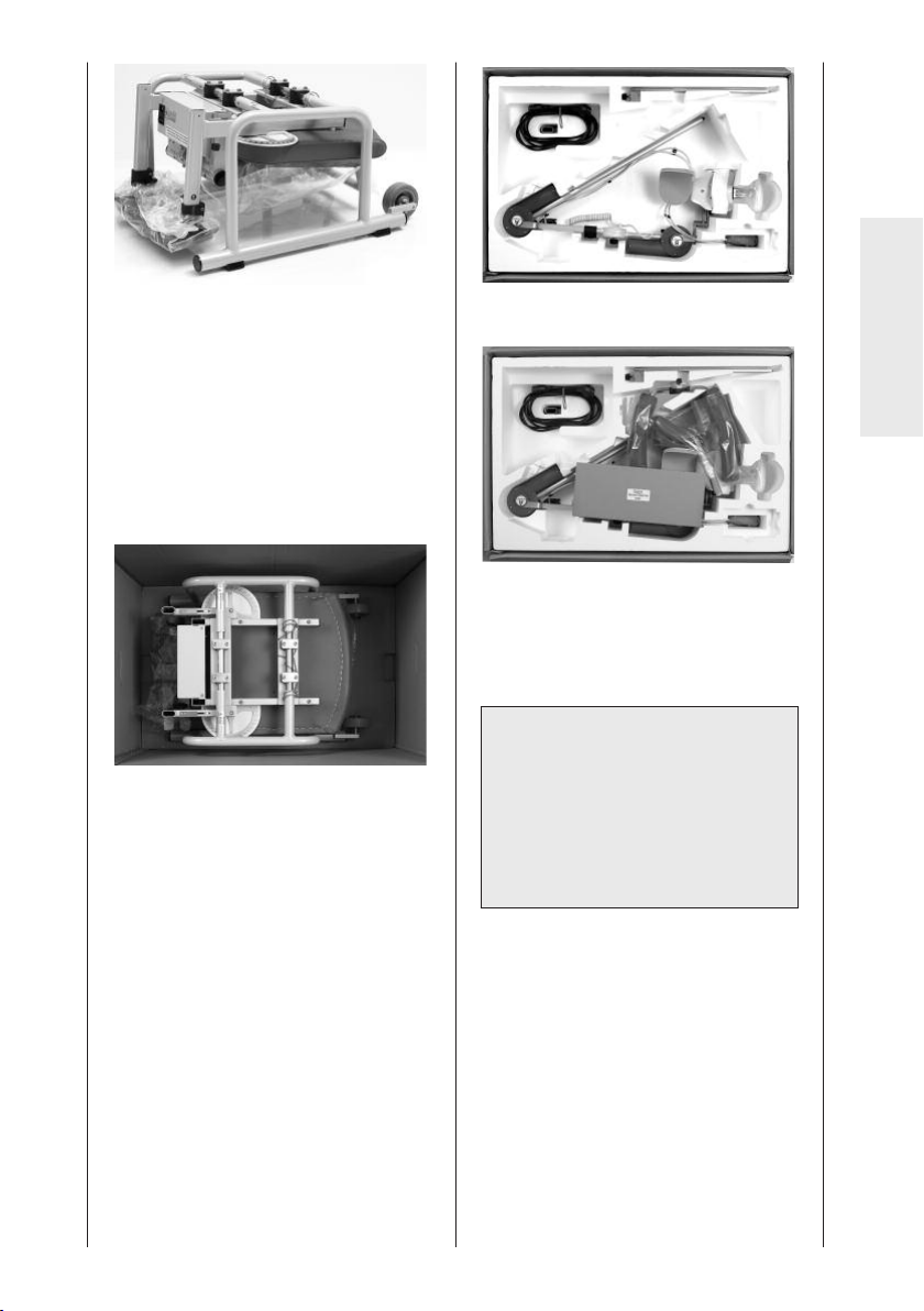
12. Only use the original shipping box
for transporting the device. Ormed
GmbH & Co. KG cannot be held
liable for transport damage, if the
device was not shipped in its
original shipping box.
13. Place the ARTROMOT
down – on the bottom of the box.
The markings on the bottom of the
box indicate the correct position.
14. Then put the enclosed polystyrene
block on the chair, observing the
cut-outs in the block.
15. Put the programming unit (1) in the
supplied box. Place the motion
element, the armrest, the components of the neck and shoulder
restraint and the power cord in the
respective cut-outs in the polystyrene block.
®
-S3 – legs
English
16. Then close the box.
Reverse the above steps to reassemble
the device after transport.
Warning!
Shock hazard – Before use allow the
ARTROMOT®-S3 to reach room
temperature. If the device has been
transported at temperatures below
0 °C (32 °F), leave it to dry at room
temperature for about 2 hours, until
any condensation has disappeared.
75
Page 76
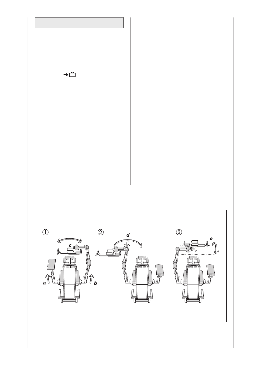
6.4 Conversion
The ARTROMOT®-S3 can be used on
the left and on the right shoulder joint.
However, the device must be converted
first. This is done very quickly.
1. Activate the "transport setting"
function in the menu (see
also 5.3) and start the
ARTROMOT
2. On both sides adjust an angle of 90°
for horizontal adduction/abduction
(indexing knob 12) (see conversion
drawing † ).
3. Open locking screw (14), remove the
armrest for the healthy arm and
place it on the seat (see conversion
diagram † a).
4. Grasping the holding tube (17) of the
motion element, open locking screw
(14).
5. Remove the motion element and
insert it on the opposite side.
Tighten locking screw (14) (see
conversion diagram † b, c).
®
-S3.
6. Open locking screw (20) and rotate
the forearm rest 180°.
Tighten locking screw (20) (see
conversion diagram Πd).
7. Hold the forearm rest and open
locking screw (28).
8. Swivel the forearm rest to the other
side around motor B and tighten
locking screw (28) (see conversion
diagram Å e).
9. Insert the armrest for the healthy
arm into the holding tube and
tighten locking screw (14).
10. Set horizontal adduction/abduction
to the desired value on the side of
the motion element (normally a value
between 0° and 40°, as needed).
Conversion diagram:
76
Page 77

7. Environmental
Protection Statement
The product described in this operation
manual must not be disposed of with
unsorted household or municipal waste.
It requires separate disposal. Please
contact ORMED for information about
the possible recycling of the product.
8. Specifications
Input ratings:
Rated current-motor: 2 A max.
Power consumption 33 VA
Fuses: 2 x T1A
Protection class: I
Applied part: type B
Dimensions (transport):
Length: 87.5 cm (34.4 in)
Width: 57.5 cm (22.6 in)
Height: 58.0 cm (22.8 in)
Adjustment ranges (min./max.):
Height adjustment: 35 – 71 cm
(measured from (13.7 – 28.0 in)
the seat)
Upper arm length: 20 – 32 cm
Forearm length: 29 – 46 cm
Seat height: 48 cm (18.9 in)
Weight: 25 kg (55.1 lbs)
Materials: ABS, POM
MDD: class 2a
100 – 240 V AC /
50 – 60 Hz
(7.8 – 12.6 in)
(11.4 – 18.1 in)
(Delrin 100),
PUR, PA, FR4,
aluminum,
stainless steel,
brass
Standards IEC 60601-
compliance: 1:1990
EMC IEC 60601-1
(Electromagnetic 2:2001
compatibility)
Ambient conditions
(storage, transport)
Ambient temperature:
Relative
humidity: 20% to 85%
Atmospheric 700 hPa to
pressure: 1060 hPa
Ambient conditions (operation)
Ambient temperature:
Relative
humidity: 30% to 75%
Atmospheric : 700 hPa to
pressure 1060 hPa
Subject to change without notice
(06/2007)
+ A1:1993
+ A2: 1995
CSA No.
601.1-M90
UL 2601-1
-24 ºC to +60 ºC
(-12 to +140 °F)
+10 ºC to +40 ºC
(50 to +105 °F)
English
77
Page 78
9. IEC 60601-1-2:2001
The ARTROMOT®-S3 device is subject
to particular precautions regarding
electromagnetic compatibility (EMC).
The device must be installed and put
into service strictly in compliance with
the EMC directives put forth in the
accompanying documents.
Portable and mobile RF communication
systems may affect the
ARTROMOT
The ARTROMOT
®
-S3 device.
®
-S3 device should not
be used adjacent to or stacked with
other equipment. If adjacent or stacked
use is necessary, ARTROMOT®-S3
should be observed to verify normal
If it is necessary to replace assemblies
or cables, only the manufacturer's
original parts must be used to ensure
continued compliance with EMC
requirements after repair. This requirement applies to the power supply unit,
cables and cable lengths, drive unit
consisting of the motor and the control
system, the programming unit incl. the
coiled cable and the connector.
®
The equipment name ARTROMOT
-S3
used below always designates all
device models such as
ARTROMOT®-S3 and ARTROMOT®-S3
comfort.
operation in the configuration in which it
will be used.
If you detect damage or malfunctions
that may impair the safety of the patient
or of the operator, have the device
repaired before using it.
9.1 Electromagnetic emissions
Guidance and Manufacturer’s Declaration – Electromagnetic Emissions
ARTROMOT®-S3 is intended for use in the electromagnetic environment specified below. It is the
responsibility of the customer or user to ensure that the ARTROMOT
an environment.
Emissions test Compliance Electromagnetic environment - guidance
RF emissions to CISPR 11 Group 1
ARTROMOT®-S3 uses RF energy only for its
internal function. Therefore, its RF emissions
are very low and are not likely to cause any
interference in nearby electronic equipment.
®
-S3 device is used in such
RF emissions to CISPR 11 Class B
Harmonic emissions to IEC
61000-3-2
Voltage fluctuations/flicker
emissions to
IEC 61000-3-3
not applicable
not applicable
ARTROMOT®-S3 is suitable for use in all
establishments, including domestic and those
directly connected to the public low-voltage
power supply network that supplies buildings
used for domestic purposes.
78
Page 79

9.2 Electromagnetic immunity
Guidance and Manufacturer’s Declaration – Electromagnetic Immunity
ARTROMOT®-S3 is intended for use in the electromagnetic environment specified below. It is
he responsibility of the customer or user to ensure that the ARTROMOT
t
uch an environment.
s
Immunity test IEC 60601 test
level
lectrostatic
E
discharge (ESD)
to
EC 61000-4-2
I
Electrical fast
transient/burst
to
IEC 61000-4-5
6 kV contact
±
8 kV air
±
± 2 kV for power
supply lines
± 1 kV for
input/output lines
Compliance
level
6 kV contact
±
8 kV air
±
± 2 kV for power
supply lines
± 1 kV for
input/output lines
Electromagnetic
environment – guidance
loors should be wood, concrete or
F
ceramic tile. If floors are covered
with synthetic material, the relative
umidity should be at least 30%.
h
Mains power should be that of a
typical commercial or hospital
environment.
®
S3 device is used in
-
English
Surges to
IEC 61000-4-5
Voltage dips,
short interruptions and
voltage variations on power
supply input
lines to IEC
61000-4-11
Power frequency
(50/60 Hz)
magnetic field to
IEC 61000-4-8
± 1 kV differential
mode
± 2 kV common
mode
< 5% U
T
(> 95% dip in UT)
1
⁄2cycle
for
40% U
T
(60% dip in UT) for
5 cycles
70% U
T
(30% dip in UT) for
25 cycles
< 5% U
T
(> 95% dip in UT)
for 5 s
± 1 kV differential
mode
± 2 kV common
mode
< 5% U
T
(> 95% dip in UT)
1
⁄2cycle
for
40% U
T
(60% dip in UT) for
5 cycles
70% U
T
(30% dip in UT) for
25 cycles
< 5% U
T
(> 95% dip in UT)
for 5 s
Mains power should be that of a
typical commercial or hospital
environment.
Mains power should be that of a
typical commercial or hospital
environment. If the user of the
ARTROMOT
continued operation during power
mains interruptions, it is recommended that the ARTROMOT
device be powered from an uninterruptible power supply or a battery.
3 A/m 3 A/m Power frequency magnetic fields
should be at levels characteristic of
a typical location in a typical
commercial or hospital environment.
NOTE: UTis the a.c. mains voltage prior to application of the test level.
®
-S3 device requires
®
-S3
79
Page 80
9.2 Electromagnetic immunity
Guidance and Manufacturer’s Declaration – Electromagnetic Immunity
RTROMOT
A
the responsibility of the customer or user to ensure that the ARTROMOT
uch an environment.
s
Immunity test IEC 60601 test
Conducted RF to
IEC 61000-4-6
Radiated RF to IEC
61000-4-3
®
S3 is intended for use in the electromagnetic environment specified below. It is
-
evel
l
Compliance
evel
l
Electromagnetic environment -
uidance
g
ortable and mobile RF communi-
P
cations equipment are used no
loser to any part of the
c
ARTROMOT
cables, than the recommended
separation distance calculated
from the equation applicable to the
frequency of the transmitter.
Recommended separation
distance:
3 Vrms
150 kHz to
80 MHz
3 V/m
80 MHz to
2.5 GHz
3 Vrms
3 V/m
d = 1.2 öäP
d = 1.2 öäP
80 MHz to 800 MHz
d = 1.2 öäP
800 MHz to 2.5 GHz
where P is the maximum output
power rating of the transmitter in
watts (W) according to the transmitter manufacturer and d is the
recommended separation distance
in meters (m).
Field strengths from fixed RF
transmitters, as determined by an
electromagnetic site survey
less than the compliance level in
each frequency range
Interference may
occur in the vicinity
of equipment marked with
the following symbol.
®
-S3 device is used in
®
-S3 device, including
b
.
a
, is
NOTE 1: At 80 MHz and 800 MHz, the higher frequency range applies.
NOTE 2: These guidelines may not apply in all situations. Electromagnetic propagation is affected
by absorption and reflection from structures, objects, and people.
a) Field strengths from fixed transmitters, such as base stations for radio (cellular/cordless)
telephones and land mobile radio, AM and FM radio broadcast and TV broadcast cannot be
predicted theoretically with accuracy. To assess the electromagnetic environment due to fixed
RF transmitters, an electromagnetic site survey should be considered. If the measured field
strength in the location in which the ARTROMOT
compliance level above, the ARTROMOT
operation. If abnormal performance is observed, additional measures may be necessary, such as
reorienting or relocating the ARTROMOT
®
-S3 device is used exceeds the applicable RF
®
-S3 device should be observed to verify normal
®
-S3 device.
b) Over the frequency range 150 kHz to 80 MHz, field strengths should be less than 3 V/m.
80
Page 81
9.3 Recommended separation distances
ecommended separation distances between portable and mobile RF communications equip-
R
ment and the ARTROMOT
The ARTROMOT®-S3 is intended for use in an electromagnetic environment in which radiated RF
disturbances are controlled. The customer or the user of the ARTROMOT
revent electromagnetic interferences by maintaining a minimum distance between portable and
p
mobile RF communications equipment (transmitters) and the ARTROMOT
ecommended below, according to the maximum output power of the communications equip-
r
ment.
rated maximum output
ower of transmitter
p
0.01 0.12 0.12 0.23
0.1 0.38 0.38 0.73
1 1.2 1.2 2.3
10 3.8 3.8 7.3
100 12 12 23
For transmitters rated at a maximum output power not listed above, the recommended separation distance d in meters (m) can be estimated using the equation applicable to the frequency of
the transmitter, where P is the maximum output power rating of the transmitter in watts (W)
according to the transmitter manufacturer.
NOTE 1: For calculation of the recommended separation distance of transmitters in the frequency
range from 80 MHz to 2.5 GHz an additional factor of 10/3 was taken into account to reduce the
probability of mobile/portable communications equipment brought into the patient environment by
accident causing any malfunction.
NOTE 2: These guidelines may not apply in all situations. Electromagnetic propagation is affected
by absorption and reflection from structures, objects, and people.
®
-S3 device
W
separation distance according to frequency of transmitter
150 kHz to 80 MHz
d = 1.2 öäP
m
80 MHz to 800 MHz
d = 1.2 öäP
®
-S3 device can help
®
-S3 device as
800 MHz to 2,5 GHz
d = 1.2 öäP
English
10. Contact
We would be happy to answer any
questions you may have about our
products and services.
■
Ormed international
Please contact your local dealer or
the ORMED headquarters in Germany.
■
Headquarters Germany
Ormed GmbH & Co. KG
Merzhauser Strasse 112
D-79100 Freiburg
Phone +49 761 45 66-01
Fax +49 761 45 66 55-01
■
Website
www.ormed.de
e-mail: [email protected]
■
Warranty:
2 years (mechanical parts)
2 years (electroncis)
■
Sales:
Ormed GmbH & Co. KG
Merzhauser Strasse 112
D-79100 Freiburg
81
Page 82
11. Technical Service
11.1 Technical hotline
Do you have any technical questions?
Do you need technical service?
Phone: +49-180-5-1 ormed de
+49-180-5-1 67 63 33
Fax: +49-180-5-3 ormed de
+49-180-5-3 67 63 33
11.2 Shipment
To prevent damage during transport,
only use the original shipping box.
These boxes can be obtained from
ORMED.
Before packing the CPM device, set it
to the transport position (see chapters 5
and 6).
11.3 Spare parts
Refer to the Service Manual for the
most recent list of spare parts.
When ordering spare parts, always
specify:
- Item
- Description
- Part number
- Quantity
- Serial number of the CPM device
Surcharges may apply in certain cases
to spare parts ordered in low quantities.
tem Description Part no. Qty
I
1. Patient chip card 0.0034.048
2. Patient chip card
protocol) 0.0037.035
(
3. Marker pen for
patient chip card 0.0031.006
Note!
Refer repairs to authorized, specially
trained staff.
ORMED GmbH & Co. KG offers
service training for your personnel.
82
Page 83

12. Declaration of conformity
Declaration of conformity
In compliance with the Council Directive 93/42/EEC of 14 June 1993
concerning medical devices, the company
ORMED GmbH & Co.KG
Merzhauser Strase 112
D-79100 Freiburg, Germany
declares that the products of the product line
ARTROMOT
fulfill the requirements of the Council Directive 93/42/EEC of 14 June
1993, Annex II as well as the essential requirements of Annex I.
0297
Freiburg, 13/06/2007
Annex:
ARTROMOT
ARTROMOT®-S3
ARTROMOT®-S3 Comfort
ARTROMOT®-K1
ARTROMOT®-K2
ARTROMOT®-K2PRO
ARTROMOT®-K2PRO Chip
ARTROMOT®-K3
ARTROMOT®-K4
ARTROMOT®-SP2
ARTROMOT®-SP3
ARTROMOT®-E2
ARTROMOT®-E2compact
®
-S2PRO
®
(see Annex)
_______________________________________
- QA Management Representative -
English
DECLA RATION OF CONFOR MITY
83
Page 84

Table des matières
Description de l’appareil 3
Illustrations 252
Symbol Overview 249
1. Informations sur l’utilisation de l’attelle de mobilisation 85
1.1 Possibilités d’utilisation 85
1.2 Objectifs de la thérapie 85
1.3 Indications 85
1.4 Contre-indications 85
®
2. Description de l’ARTROMOT
2.1 Définition des éléments fonctionnels 86
2.2 Présentation de l’unité de programmation 87
2.3 Légende des pictogrammes 90
2.4 Légende des symboles (raccords et plaque signalétique) 91
3. Consignes de sécurité 92
4. Réglage de l’appareil 95
4.1 Raccordement de l’appareil, contrôle du fonctionnement 95
4.2 Réglage de l’appareil selon les mensurations du patient 96
5. Réglage des valeurs de traitement 98
5.1 Généralités concernant la programmation de l’ARTROMOT
5.2 Programmer l’ARTROMOT
5.3 Informations relatives aux valeurs de traitement de la version Standard 100
5.4 Programmer l’ARTROMOT
5.5 Informations relatives aux programmes de la version Comfort 106
5.6 Exemple d’application / de programmation 110
6. Entretien, maintenance, transport, changement de configuration 113
6.1 Entretien 113
6.2 Maintenance (remplacement de fusibles) 113
6.3 Transport 114
6.4 Changement de configuration 116
7. Consignes relatives à l’environnement 117
8. Caractéristiques techniques 117
9. CEI 60601-1-2:2001 118
9.1 Emission électromagnétique 118
9.2 Résistance aux interférences électromagnétiques 119
9.3 Distances de sécurité recommandées 121
10. Interlocuteurs 121
11. Service technique 122
11.1 Hotline 122
11.2 Expédition 122
11.3 Pièces détachées 122
12. Déclaration de conformité 123
-S3 86
®
®
-S3 version Standard 100
®
-S3 version Comfort 105
-S3 98
84
Page 85

1. Informations sur l’utilisation de l’attelle de
mobilisation
1.1 Possibilités d’utilisation
L’ARTROMOT®-S3 est une attelle de
mobilisation motorisée axée sur le
mouvement passif continu (Continuous
Passive Motion = CPM) de l’articulation
de l’épaule.
Conçu pour être utilisé en
clinique/cabinet médical ou chez un
particulier (location), cet appareil
constitue un complément essentiel au
traitement médico-thérapeutique.
1.2 Objectifs de la thérapie
La thérapie de mouvement au moyen
de l’attelle de mobilisation
ARTROMOT
à prévenir des dommages découlant
d’une immobilisation, à retrouver
rapidement une mobilité de l’articulation
exempte de douleurs ainsi qu’à accélérer le processus de guérison avec un
bon résultat fonctionnel.
Ci-dessous d’autres objectifs visés par
cette thérapie :
- Amélioration du métabolisme de
l’articulation
- Prévention contre les raideurs articulaires (arthrofibrose)
- Aide à la reconstruction de zones
cartilagineuses et à la guérison de
blessures aux ligaments
- Résorption des épanchements plus
rapide
- Amélioration de la circulation sanguine
et lymphatique
- Prévention contre les thromboses et
les embolies
®
-S3 sert en première ligne
1.3 Indications
L’attelle de mobilisation est appropriée
au traitement des blessures les plus
courantes, des états post-opératoires
ainsi que des maladies des articulations
de l’épaule, telles que :
- Distorsions et contusions articulaires
- Arthrotomies et arthroscopies combinées à une synovectomie, une arthrolyse ou d’autres mesures intra-articulaires
- Arthroplasties en tout genre
- Mobilisation de l’articulation pendant
une anesthésie
- Fractures traitées chirurgicalement,
pseudarthroses, dans la mesure où
elles peuvent supporter des exercices
- Opérations de décompression (acromioplastie)
- Implantations d’endoprothèses
- Interventions sur les tissus axillaires et
dans la région de la ceinture
- Traitements chirurgicaux de tumeurs
dans la zone de l’épaule
1.4 Contre-indications
Il est défendu d’utiliser
l’ARTROMOT
vants :
- Inflammations articulaires aiguës, si le
médecin ne l’a pas prescrit expressément
- Paralysies spastiques
- Ostéosynthèses instables
®
–S3 dans les cas sui-
Français
85
Page 86

2. Description de l’ARTROMOT®-S3
Cette attelle de mobilisation motorisée
permet de faire bouger l’articulation de
l’épaule comme suit :
Adduction / abduction 0° - 30° - 175°
Rotation
interne / externe 90° - 0° - 90°
Elévation (flexion) 0° - 30° - 175°
avec le coude fermé à
un angle de 60° - 90°
Antéversion /
Rétroversion 0° - 120°
(adduction / abduction horizontale)
Réglable uniquement à la main
Elle peut être utilisée des deux côtés,
en modifiant son montage.
Remarque !
Pour permettre une représentation
claire de la position actuelle de
l’attelle de mobilisation, les valeurs
relatives à la rotation interne sont
indiquées entre guillemets («–») à
l’écran ainsi que dans le mode
d’emploi.
®
L’ARTROMOT
autres, par les caractéristiques suivantes :
- Possibilité de réglage adapté à
l’anatomie
- Mouvements physiologiques
- Amplitudes de mouvements maximales
- Unité de programmation pour
l’ajustage de toutes les valeurs de
traitement
- Carte à puce pour l’enregistrement
des valeurs programmées
- Transport aisé
Compatibilité biologique
Les parties de l’ARTROMOT
conformément à l’usage défini, entrent
en contact avec le patient sont conçues
de sorte à satisfaire aux exigences en
matière de compatibilité biologique
énoncées dans les normes applicables.
-S3 se distingue, entre
®
-S3 qui,
2.1 Définition des
éléments fonctionnels
Remarque :
veuillez déplier la page 3 !
1 Unité de programmation
2. Carte à puce patient
3. Compartiment de rangement pour
l’unité de programmation
4. Appui-bras pour le bras sain
5. Roulettes de transport
6. Raccord pour le branchement de
l’appareil
7. Interrupteur principal Marche/Arrêt
8. Fusible de sécurité de l’appareil
9. Fiche pour l’élément de mobilisation
10. Vis papillon pour régler l’inclinaison
du dossier
11. Dispositif pour rabattre le dossier
(position de transport)
12. Réglage pour l’antéversion / la
rétroversion (adduction / abduction
horizontale)
13. Tube de positionnement pour le
réglage en hauteur
14. Vis de blocage pour le réglage en
hauteur
15. Tube télescopique pour le réglage
en hauteur
16. Moteur A
17. Tube de positionnement pour le
réglage de la longueur du bras
18. Levier de blocage pour le réglage
de la longueur du bras
19. Tube télescopique pour le réglage
de la longueur du bras
20. Vis de blocage pour le réglage
angulaire du coude
21. Moteur B
22. Appui-coude
23. Appui de l’avant-bras
24. Sangle de fixation de l’avant-bras
25. Tube de positionnement pour le
réglage de la longueur de l’avantbras
26. Levier de blocage pour le réglage
de la longueur de l’avant-bras
27. Tube télescopique pour le réglage
de la longueur de l’avant-bras
86
Page 87
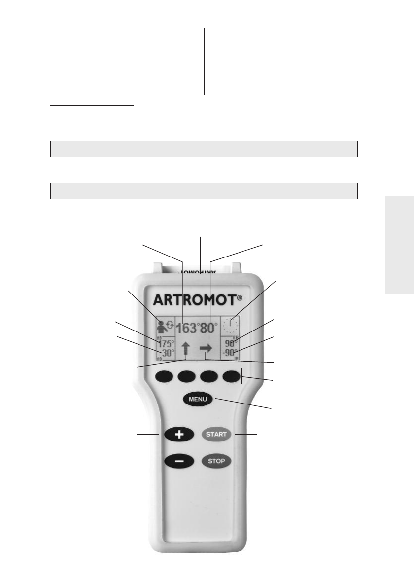
28. Vis de blocage pour le mécanisme
de pivotement
29. Poignée
30. Réglage en profondeur du repose-
1
tête
31. Réglage en hauteur de la fixation
des épaules
1
Valable uniquement pour l’ARTROMOT®-S3 comfort
1
32. Réglage en hauteur de la fixation du
33. Articulation sphérique du repose-
patient
1
tête
1
34. Goupilles de sécurité
Sous réserve de modifications tech-
niques (06/2007)
2.2 Présentation de l’unité de programmation
2.2.1 Unité de programmation en mode de fonctionnement normal
Carte à puce patient
Angle actuel Moteur A
Programme de thérapie
programmé
Angle actuel Moteur B
Affichage de la
durée de la thérapie
Français
Valeur d’abduction
programmée
Valeur d’adduction
programmée
Sens de marche
actuel Moteur A
Touche « + »
Touche « - »
Valeur de rotation
externe programmée
Valeur de rotation
interne programmée
Sens de marche
actuel Moteur B
Touches de
paramètres
Touche MENU
Touche START
Touche STOP
87
Page 88
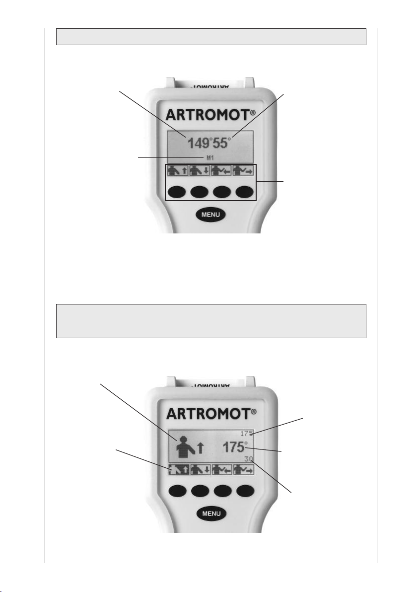
2.2.2 Unité de programmation en mode de sélection de menus
Angle actuel de l’attelle de
mobilisation en
abduction / adduction
Niveau de menu actuel
Angle actuel de
l’attelle de mobilisation en rotation
interne / externe
Paramètres disponibles au choix et
touches de paramètres afférentes
2.2.3 Unité de programmation en mode programmation
Amplitude de mouvement
Fonction sélectionnée
Paramètre activé
(ici l’abduction )
Valeur maximale
programmée actuelle
de l’abduction ou de
la rotation externe (ici
l’abduction)
Angle actuel de l’attelle de mobilisation
Abduction / adduction ou Rotation
interne / externe
Valeur maximale
programmée actuelle
de l’adduction / la
rotation interne
(ici l’adduction )
88
Page 89
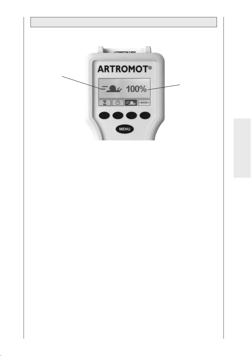
2.2.4 Unité de programmation en mode programmation général
Fonction sélectionnée
Etat actuel de la
fonction sélectionnée
(ici la vitesse )
Français
89
Page 90
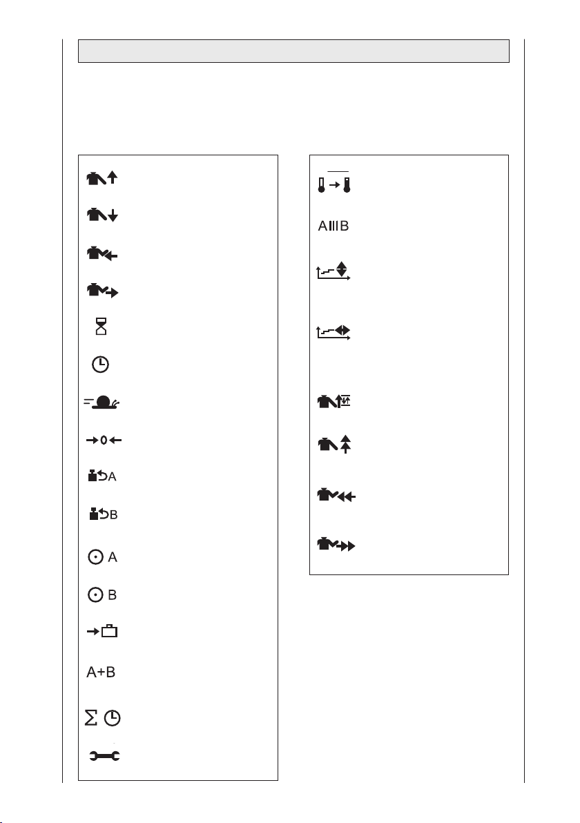
2.3 Légende des pictogrammes
Voir aussi le tableau synoptique des pictogrammes à la page 249.
Programmes Standard : Programmes Comfort :
Abduction
Adduction
Rotation interne
Rotation externe
Pause
Minuterie
Vitesse
Nouveau patient
Inversion de la charge
Moteur A
Inversion de la charge
Moteur B
Moteur A Marche/Arrêt
Programme
d’échauffement
Programme d’isolation
Suivi du déroulement de la
thérapie
Abduction / adduction
Suivi du déroulement de la
thérapie
Rotation interne / rotation
externe
Oscillation
Allongement de
l’abduction
Allongement de la rotation
interne
Allongement de la rotation
externe
Moteur B Marche/Arrêt
Réglage pour le transport
Mode de fonctionnement
synchrone / asynchrone
Durée totale de la thérapie
Menu maintenance
90
Page 91
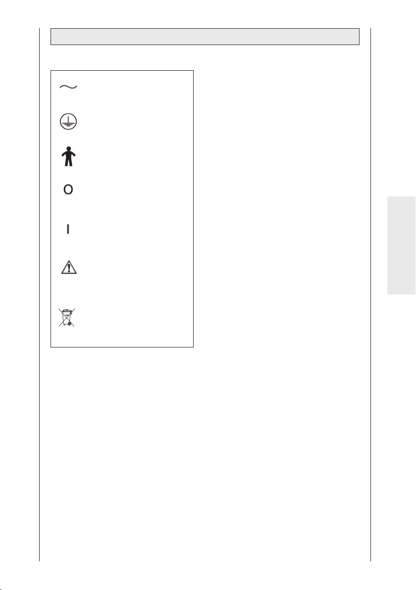
2.4 Légende des symboles (raccords et plaque signalétique)
Courant alternatif
Raccord du conducteur
de protection
Partie appliquée type B
Interrupteur principal
ARRÊT
Interrupteur principal
MARCHE
Respecter les indications
figurant sur les papiers
d’accompagnement
Ne pas éliminer avec les
déchets ménagers non
triés
Français
91
Page 92

3. Consignes de sécurité
Explication
Vous devez impérativement lire les
consignes de sécurité avant de procéder à la mise en service de l’attelle de
mobilisation. Ces consignes sont
réparties en différentes catégories dont
voici les définitions :
Danger !
Attire votre attention sur un danger
imminent. L’inobservation de cette
consigne entraîne la mort ou des
blessures extrêmement graves.
Avertissement !
Attire votre attention sur un risque.
L’inobservation de cette consigne
peut entraîner la mort ou des blessures extrêmement graves.
Attention !
Attire votre attention sur une situation
pouvant comporter des risques.
L’inobservation de cette consigne
peut entraîner des blessures légères
et/ou endommager le produit.
Consignes de sécurité
Danger !
Risque d’explosion
®
L’ARTROMOT
à fonctionner dans des zones soumises à un risque d’explosion, situées
dans des pièces utilisées à des fins
médicales. Des zones peuvent être
soumises à un risque d’explosion
lorsque des produits anesthésiques
inflammables, des produits pour
nettoyer ou désinfecter la peau sont
utilisés.
-S3 n’est pas destinée
Avertissement !
Danger pour le patient
®
– L’ARTROMOT
pulée uniquement par des per-
sonnes autorisées. Ces personnes
auront suivi une formation sur la
manipulation de l’appareil et pris
connaissance du contenu du
présent mode d’emploi.
– Avant chaque emploi, l’utilisateur
doit s’assurer de la sécurité de
fonctionnement et de l’état
conforme de l’appareil. Il faut vérifier
en particulier que les dispositifs
enfichables et les câbles ne sont
pas endommagés. Les pièces
endommagées doivent immédiatement être remplacées.
– Avant le début du traitement, un
essai doit être réalisé avec plusieurs
cycles de mouvement tout d’abord
sans, puis avec un patient. Vérifiez
que toutes les vis de réglage sont
bien bloquées.
– La thérapie doit être interrompue
dès que survient le moindre doute
quant au réglage correct de
l’appareil et/ou à la programmation.
– Il faut respecter le réglage correct
de l’appareil de sorte qu’il soit
adapté à l’anatomie du patient. A
cet effet, il convient de contrôler les
réglages / positionnements
suivants :
(voir numérotation sur l’appareil) :
1. Antéversion / rétroversion
(Adduction / abduction horizontale)
2. Réglage en hauteur
3. Réglage de la longueur du bras
4. Réglage de l’angle du coude
5. Réglage de la longueur de l’avantbras
-S3 doit être mani-
92
Page 93

6. Réglage du repose-tête
En cas d’utilisation de l’option
Fixation du patient
1
7. Réglage en hauteur et en profondeur du repose-tête et de la fixation
des épaules
1
– Les réglages de 1 à 7 ne doivent
être modifiés que quand aucun
patient ne se trouve sur l’attelle.
– Pendant le mouvement, le patient
ne doit ressentir aucune douleur ni
irritation.
– Pendant l’instruction et l’utilisation
de l’attelle, le patient doit être
pleinement conscient.
– Le choix des paramètres de
traitement à programmer, y compris
des programmes de thérapie à
utiliser, peut et doit être effectué
uniquement par le médecin traitant ou le thérapeute.
Au cas par cas, le médecin ou le
thérapeute doit décider si l’attelle de
mobilisation doit être utilisée ou non
pour un patient.
– Le fonctionnement de l’unité de
programmation de l’ARTROMOT
®
-S3
doit être expliqué au patient et celleci doit se trouver à sa portée afin
qu’il puisse interrompre la thérapie
si nécessaire. Pour des patients qui
ne peuvent pas manipuler l’unité de
programmation, par ex. en cas de
paralysie, le traitement peut être
effectué uniquement sous la surveillance permanente d’un personnel
spécialisé.
– Une fois les données enregistrées,
la carte à puce patient doit être
pourvue du nom du patient et ne
doit être utilisée que par celui-ci. Si
la carte à puce patient est employée
pour une autre personne, il faut
s’assurer que les données du
patient précédent soient effacées
(voir chapitres 4.1 et 5.3, section
« Nouveau patient »).
Seules des cartes à puce d’origine
doivent être utilisées.
1
Valable uniquement pour l’ARTROMOT®-S3 comfort
93
– L’ARTROMOT®-S3 ne doit être
exploitée qu’avec des accessoires
qui ont été validés par la société
ORMED.
– Veillez à ce qu’aucun membre du
patient ni objet (couverture, coussin, câble, etc.) ne puisse se retrouver entraîné dans les parties
mobiles de l’attelle.
Avertissement !
Risque d’électrocution
Les consignes d’avertissement
suivantes doivent être impérativement
respectées. Sans quoi, l’utilisateur ou
les personnes auxiliaires peuvent se
trouver en danger de mort.
– Avant la mise en service, il faut
s’assurer que l’ARTROMOT®-S3 a
atteint la température ambiante. S’il
s’avère nécessaire de transporter
l’appareil par des températures en
dessous de zéro, il faut le laisser
environ deux heures dans la pièce
de manière à laisser s’évaporer l’eau
de condensation qui s’est éventuellement formée.
®
– L’ARTROMOT
tée uniquement dans des pièces
exemptes de toute humidité.
– Afin de couper l’appareil du secteur,
veuillez toujours débrancher d’abord
la fiche de la prise murale, puis le
câble de raccordement.
– Afin de couper l’appareil du secteur,
veuillez toujours débrancher d’abord
la fiche de la prise murale, puis le
câble de raccordement. Si vous
avez des questions à ce sujet,
veuillez contacter la société
ORMED.
– Il est interdit d’utiliser des rallonges
avec multiprises pour l’amenée du
courant. L’ARTROMOT
être branchée uniquement sur une
prise de courant de sécurité
installée dans les règles de l’art.
-S3 doit être exploi-
®
-S3 doit
Français
Page 94

Auparavant, il faut dérouler entièrement le câble de raccordement de
l’appareil et le poser de sorte qu’il
ne puisse se retrouver entraîné entre
des parties mobiles lors du fonctionnement de l’appareil.
– Avant d’effectuer des travaux de
remise en état et de nettoyage, la
fiche secteur doit être retirée de
la prise.
– Du liquide ne doit en aucun cas
pénétrer dans l’attelle de mobilisation ni dans l’unité de programmation. Si cela se produit,
l’ARTROMOT
remise en service qu’après avoir été
contrôlée par le service après-vente.
®
-S3 ne doit être
– Contrôlez l’ARTROMOT®-S3 au
moins une fois par an afin de
repérer d’éventuels endommagements ou raccords desserrés.
Attention !
Marques de pression et de frottement
Dans le cas de patients obèses,
particulièrement grands et très
petits, veillez à éviter la formation de
marques de pression et marques
provoquées par frottement.
Danger pour le patient, endommagement de l’attelle L’attelle de mobilisation ne doit pas être utilisée pour
transporter des personnes.
Avertissement !
Dysfonctionnements de l’appareil
– Des champs magnétiques et élec-
triques peuvent nuire au bon fonctionnement de l’appareil. Lors de
son utilisation, veillez à ce que tous
les autres appareils exploités à
proximité soient conformes aux
exigences CEM essentielles. Les
appareils radiologiques, tomographes, installations radioélectriques, téléphones portables, etc.
peuvent perturber d’autres appareils
parce que, comme cela est permis,
ils peuvent dégager des perturbations électromagnétiques plus
importantes. Gardez une distance
suffisante par rapport à ces appareils et contrôlez le fonctionnement
avant l’utilisation.
– Les travaux d’entretien et de
remise en état doivent être réalisés
uniquement par des personnes
autorisées.
– Tous les câbles doivent être
posés de sorte à ne pouvoir se
retrouver entraînés dans des parties
mobiles pendant le fonctionnement
de l’appareil et à ce qu’il n’y ait
aucun risque de trébucher dessus.
Attention !
Endommagements de l’appareil
– Assurez-vous que les valeurs
caractéristiques de votre réseau de
distribution concordent avec les
valeurs de tension et de fréquence
figurant sur la plaque signalétique.
– La charge maximale de la surface
d’assise s’élève à 150 kg.
– Veillez à ce qu’aucun objet (couver-
ture, coussin, câble, etc.) ne puisse
se retrouver entraîné dans les
parties mobiles de l’attelle.
®
– N’exposez pas l’ARTROMOT
un rayonnement du soleil direct, des
composants risquant de devenir
beaucoup trop chauds.
– Tenez compte du fait que les fiches
ne peuvent être insérées que dans
une certaine position et protégez
toujours le connecteur à fiche en le
verrouillant.
-S3 à
94
Page 95
4. Réglage de l’appareil
Remarque : en dépliant la page 3 et
252, vous trouverez une illustration
des différentes étapes !
4.1 Raccordement de
l’appareil, contrôle du
fonctionnement
1. Branchez le câble de raccordement à
la prise (6) de l’appareil, puis la fiche
secteur dans une prise de courant de
sécurité (100-240 volts, 50/60 hertz).
2. Allumez l’appareil via l’interrupteur
principal (7).
3. Amenez maintenant l’attelle de
mobilisation en position de base
comme suit :
Premier réglage pour de nouveaux
patients
Notez le nom du patient sur le verso de
la carte à puce. Insérez la carte à puce
patient originale (2) dans l’unité de
programmation (1).
Sur l’unité de programmation, appuyez
trois fois sur la touche MENU afin
d’accéder au niveau de programmation
3 (à chaque pression de cette touche,
vous passez au niveau suivant).
Pressez la touche de paramètre « Nouveau patient » et activez cette
fonction (cochez le cercle à côté de
cette fonction).
Appuyez sur la touche START. L’attelle
rejoint automatiquement sa position de
base.
Réglage avec une carte à puce déjà
programmée
Insérez la carte à puce patient originale
(2) dans l’unité de programmation (1).
Appuyez sur la touche START.
L’attelle se déplace automatiquement
sur la position de départ (valeur
d’adduction maximale, valeur moyenne
de la rotation interne / externe).
Contrôle du fonctionnement
Si l’unité de programmation se laisse
manipuler comme décrit précédemment
et que l’ARTROMOT
position de base (voir les valeurs de
celle-ci au chapitre 5.3), cela signifie
que l’appareil fonctionne parfaitement.
Pendant son fonctionnement, l’appareil
effectue en interne un contrôle de
fonctionnement continu. S’il détecte un
défaut,
– un signal d’avertissement retentit,
– l’appareil s’arrête sur-le-champ,
– le message « ERROR » ainsi qu’un
code d’erreur (par ex. ERROR 5)
s’affichent.
Vous pouvez dans ce cas tenter de
le redémarrer en coupant brièvement
l’interrupteur principal puis en le
réactionnant. Si le message d’erreur
n’a pas disparu, il ne faut pas
réutiliser l’appareil avant de l’avoir
fait contrôler par le service aprèsvente.
®
-S3 se met en
Français
Une fois que vous vous êtes bien
assuré que l’ARTROMOT
tionne parfaitement, invitez le patient à
prendre place sur l’ARTROMOT®-S3.
95
®
-S3 fonc-
Page 96
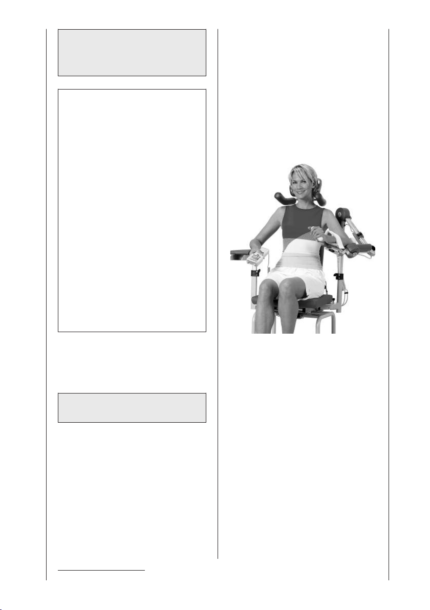
4.2 Réglage de l’appareil
selon les mensurations
du patient
Remarque !
Lors des réglages suivants, le patient
ne doit pas encore avoir placé son
bras sur l’appui-bras. Une fois que
vous avez pré-réglé l’attelle en fonction des mensurations du patient,
vous devez alors contrôler les réglages
et procéder à un ajustage avec le bras
du patient placé sur l’appui-bras.
Les réglages sont numérotés de 1 à 5.
Ces numéros sont apposés sur
l’attelle à des fins d’orientation.
Procédez toujours aux réglages dans
cet ordre.
Notez les valeurs de réglage sur le
verso de la carte à puce patient.
Avant de commencer le réglage
précis de l’ARTROMOT
mensurations du patient, le montage
de l’attelle doit, le cas échéant, être
modifié pour l’épaule gauche ou
droite (voir chapitre 6.4 « Changement
de configuration »).
®
-S3 selon les
• Réglez ensuite le repose-tête
1
:
réglage en hauteur via la vis de
blocage (32), réglage en profondeur
via la vis de blocage (30), ajustement
via l’articulation sphérique (33).
• Positionnez la fixation des épaules
avec la vis de blocage (31) à env.
1 cm au-dessus des épaules
• Positionnez l’appui-braspour le bras
sain à une hauteur telle que le patient
soit assis droit (vis de blocage 14).
Réglage anatomiquement correct
1
Avant de commencer le traitement, les
réglages suivants sont à effectuer :
Dossier, repose-tête, fixation des
épaules, appui-bras
Avant de commencer avec les réglages
proprement dits, vous devez amener le
patient dans une position anatomiquement correcte.
• Desserrez la vis papillon (10) et
amenez le dossier dans une position
agréable pour le patient (fig. F).
1
Valable uniquement pour l’ARTROMOT®-S3 comfort
96
Page 97

Antéversion / rétroversion (fig. A)
†
(adduction / abduction horizontale)
Ce réglage a pour but de permettre au
patient de prendre une position la plus
confortable possible.
Remarque !
Une modification de l’angle du coude
sur une flexion inférieure ou supérieure à 90° change par là-même le
réglage de la longueur du bras.
• Appuyez sur le bouton d’arrêt (12) et
veillez, une fois le réglage achevé, à
ce qu’il se renclenche correctement.
Réglage en hauteur (fig. B)
Œ
Avant de desserrer la vis de blocage
(14), vous devez saisir et maintenir la
partie mobile de l’attelle afin qu’elle ne
tombe pas vers le bas ; le mieux étant
de la saisir au niveau du tube de
positionnement pour le réglage en
longueur.
• Réglez la hauteur de manière à ce
que l’axe du moteur A soit aligné avec
le pivot de l’articulation de l’épaule
(voir p. 96 sur la figure). Le pivot du
moteur A doit coïncider avec celui de
l’articulation de l’épaule.
• Resserrez à fond la vis de blocage.
Longueur du bras (fig. C)
Å
Le mécanisme de réglage de la
longueur du bras est autobloquant.
Lors du réglage, vous devez en même
temps soulever légèrement le moteur B
et veiller à ce que le tube téléscopique
ne se coince pas.
• Desserrez le levier de blocage (18) et
soulevez légèrement le moteur
pendant la durée du réglage.
• Rabaissez le levier de blocage.
Angle du coude (fig. D)
è
En règle générale, le coude est positionné à un angle de flexion situé entre
90° et 60°.
• Desserrez la vis de blocage (20). Pour
faciliter le réglage, soulevez légèrement le moteur B.
• Procédez au réglage souhaité et
resserrez la vis de blocage.
Longueur de l’avant-bras (fig. E)
ì
• Desserrez le levier de blocage (26) et
tirez la poignée jusqu’à une position
permettant à l’avant-bras de prendre
place aisément entre l’appui-coude et
la poignée.
• Rabaissez le levier de blocage.
Remarque !
L’inclinaison de l’appui-bras peut être
réglée afin d’être adaptée de manière
exacte au patient.
A cet effet, desserrez la vis de blocage (28) située sous l’appui-bras.
Réglez l’inclinaison souhaitée et
resserrez la vis de blocage.
Contrôle des réglages, ajustement
• Placez le bras du patient sur l’appuibras.
• Contrôlez les réglages décrits aux
points 1 à 5 et assurez-vous que
– le pivot du moteur A coïncide avec
celui de l’articulation de l’épaule
– l’axe du moteur B, le centre de
l’articulation du coude et de celle
de l’épaule forment une ligne.
Pour un ajustement précis, l’appuibras peut, en outre, être réglé en
hauteur et inclinaison. A cet effet,
desserrez la vis de blocage (28)
située sous l’appui-bras.
• Assurez-vous que toutes les vis de
blocage sont bien serrées et tous les
leviers de blocage correctement
rabaissés.
Français
97
Page 98

5. Réglage des valeurs de traitement
Avertissement !
Danger pour le patient
Avant de débuter le traitement, un
essai doit être réalisé avec plusieurs
cycles de mouvement sans patient.
Effectuez ensuite un essai avec un
patient en veillant à ce qu’il ne ressente aucune douleur pendant les
mouvements.
Remarque : voir aussi les points 2.2
et 2.3, et se reporter à la page 249.
Remarque !
La programmation est possible
uniquement si la carte à puce patient
est insérée.
Vous trouverez des informations
relatives aux valeurs de traitement et
à la programmation des fonctions et
des fonctions spéciales aux chapitres
5.1 à 5.5.
Vous trouverez des exemples de
programmation au chapitre 5.6.
Important !
L’unité de programmation
ARTROMOT®-S3 « Graphique » peut
être raccordée à tous les produits de
la gamme ARTROMOT®pour l’épaule
à partir du numéro de série supé-
rieur à 3000.
Un remplacement des cartes à puce
entre les versions « Texte » et « Graphique » est possible.
Il faut ici veiller aux points suivants :
1. Si une unité de programmation de
la version « Graphique » doit être
exploitée avec une carte à puce
formatée de la version « Texte »,
- le réglage de la langue de la
version « Texte » reste conservé ;
il est sans importance pour le
fonctionnement de la version
« Graphique ».
- l’inversion de la charge enregis-
trée dans la version « Texte » est
automatiquement prise en compte
pour les deux moteurs.
- le verrouillage des touches est
inactif.
2. Si une unité de programmation de
la version « Texte » doit fonctionner
avec une carte à puce formatée de
la version « Graphique »,
- le réglage de la langue est
automatiquement réinitialisé sur le
réglage usine, soit l’allemand.
- l’inversion de la charge enregis-
trée dans la version « Graphique »
pour le moteur A est automatiquement prise en compte pour les
deux moteurs.
- le verrouillage des touches
éventuellement réglé dans la
version « Graphique » est
conservé ; il n’a aucun effet pour
le fonctionnement de la version
« Texte », dans la version
« Texte », il n’est pas prévu.
5.1 Généralités concernant
la programmation de
l’ARTROMOT®-S3
1. En appuyant brièvement sur la
touche MENU de votre unité de
programmation, vous passez en
mode programmation.
2. Les différents paramètres de traitement et fonctions sont répartis sur
quatre niveaux de programmation
différents (versions Standard) ou six
(versions Comfort) - au nombre de 4
par niveau. Afin de programmer un
paramètre, vous devez appeler le
niveau de programmation correspondant. Pour ce faire, appuyez sur la
touche MENU. A chaque fois que
vous pressez à nouveau cette
touche, vous passez au niveau
suivant. Au centre de l’affichage,
vous voyez quel niveau de program-
98
Page 99
mation vous venez d’appeler (M1,
M2, etc.).
3. Vous appelez le paramètre de traitement ou les fonctions à l’aide d’une
des quatre touches de paramètres
situées en dessous de l’affichage.
Pour savoir quels paramètres ou
fonctions sont attribués à ces quatre
touches, veuillez vous référer aux
symboles situés au-dessus.
Dès que vous sélectionnez un
paramètre en appuyant sur la touche
de paramètre correspondante,
• le symbole afférent s’affiche en
grand,
• la valeur actuellement réglée
apparaît à l’écran,
• le symbole au-dessus de la touche
de paramètre est représenté sur
fond sombre.
4. Avec les touches + / -, vous modifiez
la valeur (elle change rapidement
lorsque vous maintenez la touche
enfoncée).
Seules quelques fonctions / fonctions
spéciales s’activent ou se désactivent. Pour ce faire, appuyez à nouveau sur la touche de paramètre
correspondante ou utilisez les
touches + / -. Quand le paramètre est
activé, le cercle situé près du symbole est coché.
5. Une fois que tous les paramètres ont
été programmés, enregistrez les
valeurs avec la touche STOP.
6. Appuyez ensuite sur la touche
START : L’ARTROMOT
®
-S3 vérifie les
valeurs réglées, se déplace sur la
position correspondant à la moyenne
de la valeur de rotation interne et
celle de rotation externe réglées ainsi
que sur la valeur d’adduction réglée
et s’arrête.
7. Pressez à nouveau la touche START
afin de débuter le traitement.
L’attelle se déplace ensuite en mode
synchrone tout d’abord sur la valeur
de rotation interne maximale. Puis
elle se positionne sur la valeur de
rotation externe maximale et la valeur
d’abduction maximale, et enfin sur la
valeur d’adduction maximale et celle
de rotation interne maximale. Une
fois cette position atteinte, le cycle
de mouvement reprend depuis le
début avec le positionnement de
l’attelle sur le point correspondant à
la valeur d’abduction maximale et à
la valeur de rotation externe maximale.
En mode asynchrone, dès que la
touche START est pressée, les deux
moteurs commencent à fonctionner
de manière aléatoire ; chaque moteur
changeant de sens une fois les
valeurs maximales atteintes.
Remarque !
- Vous trouverez une description des
paramètres aux points 5.3 et 5.5.
- Vous pouvez afficher les paramè-
tres réglés via la touche de paramètre correspondante. A cette fin, vous
devez d’abord presser la touche
STOP, puis passer au niveau de
menu voulu.
- Afin d’empêcher une modification
par inadvertance des paramètres,
vous pouvez, en pressant simultanément les touches + et –, bloquer les
touches.
-
Pour les déverrouiller, appuyez une
nouvelle fois sur ces deux touches.
- Les données contenues sur la carte
à puce patient sont effacées automatiquement avec la fonction
« Nouveau patient ». En pressant la
touche STOP à la fin de la programmation, les réglages sont aussi
mémorisés automatiquement sur la
carte à puce patient.
- Fonction d’arrêt d’urgence : Dès
qu’une touche quelconque est
pressée pendant le traitement,
l’ARTROMOT
immédiatement.
Le traitement peut être poursuivi en
appuyant sur START. L’appareil
change alors automatiquement le
sens du mouvement.
99
®
-S3 se déconnecte
Français
Page 100
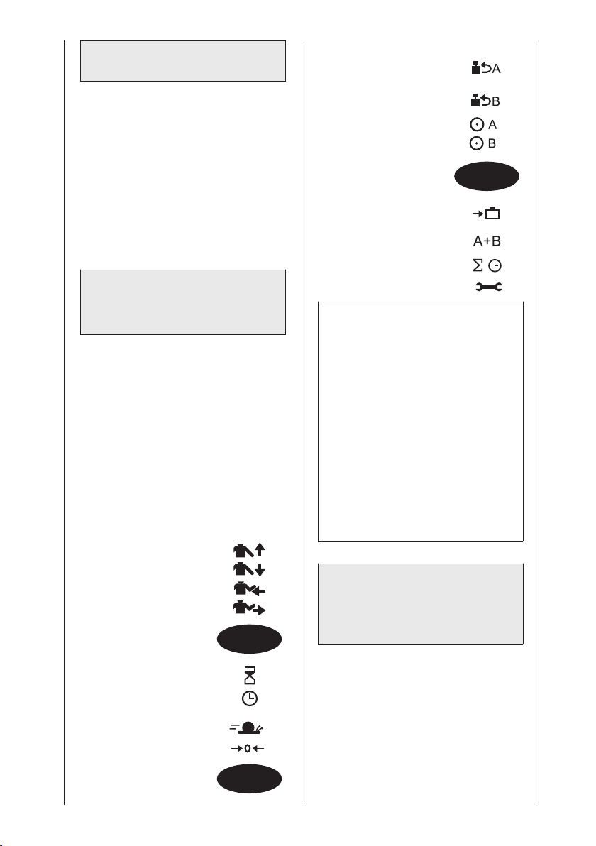
Patients avec une carte à puce
programmée
• Commencez par effectuer les
réglages mécaniques.
• Insérez ensuite la carte à puce (le
patient ne doit pas encore être installé
sur l’attelle de mobilisation).
• Appuyez sur la touche START :
l’attelle de mobilisation se déplace sur
la position de départ des paramètres
enregistrés sur la carte à puce et
s’arrête.
• Aidez ensuite le patient à prendre
place sur l’attelle et appuyez sur
START afin de débuter le traitement.
5.2 Programmer
l’ARTROMOT®-S3
version Standard
La programmation des différents
réglages de l’ARTROMOT
s’effectue sur plusieurs niveaux de
programmation.
Chaque nouvelle pression de la touche
MENU vous fait changer de niveau.
Le niveau actuellement sélectionné
apparaît à l’écran.
Les valeurs de traitement, réglages et
affichages suivants peuvent être
entrés / appelés via l’unité de programmation (1) :
NIVEAU 1 :
- Abduction
- Adduction
- Rotation interne
- Rotation externe
NIVEAU 2 :
- Pause
- Minuterie
(durée de la thérapie)
- Vitesse
- Nouveau patient
®
-S3 Standard
MENU
MENU
NIVEAU 3 :
- Inversion de la charge
Moteur A
- Inversion de la charge
Moteur B
- Moteur A Marche/Arrêt
- Moteur B Marche/Arrêt
NIVEAU 4 :
- Réglage pour le transport
- Mode de fonctionnement
synchrone / asynchrone
- Durée totale de la thérapie
- Menu maintenance
Remarque !
• Pendant le réglage des valeurs,
l’appareil se déplace dans la plage
réglée. L’amplitude du mouvement
exempt de douleurs peut ainsi être
enregistrée facilement et rapidement.
• Concernant l’attelle de mobilisation
ARTROMOT
fonctions spéciales peuvent être
en plus programmées et appelées
(voir chapitres 5.4 et 5.5).
• Le dernier angle configuré lors de la
programmation d’un sens de
mouvement donné est immédiatement enregistré.
®
-S3 Comfort, des
5.3 Informations relatives
aux valeurs de
traitement de la version
Standard
• Vous sélectionnez le niveau de
programmation souhaité en appuyant
plusieurs fois sur la touche MENU.
• Vous sélectionnez les paramètres de
traitement via la touche de paramètre
afférente.
• Vous modifiez les valeurs de traite-
ment avec les touches + / -.
• Vous activez / désactivez une fonction
en pressant une nouvelle fois la
100
MENU
 Loading...