

Page 1
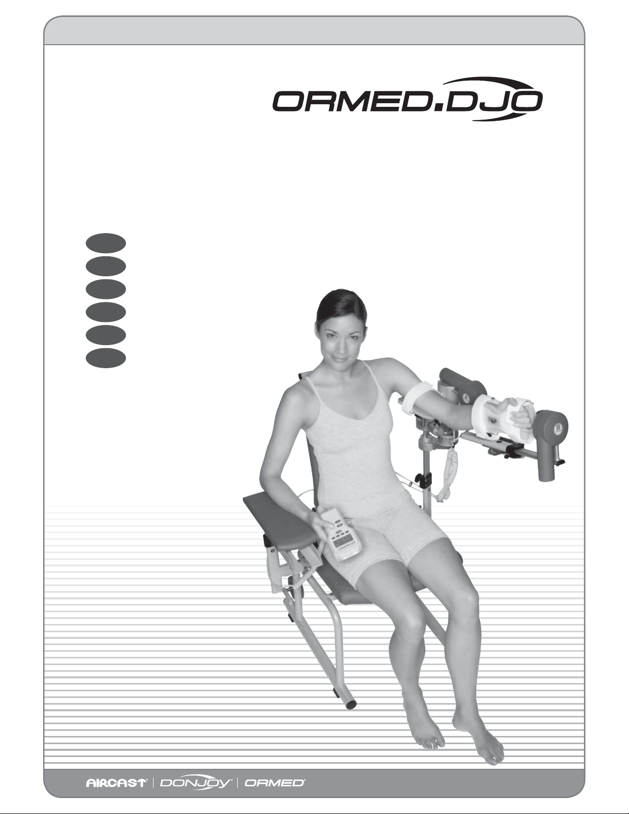
ARTROMOT®-E2
ARTROMOT®-E2 COMPACT
Gebrauchsanweisung
D
Operation Manual
E
Mode d‘emploi
F
Modo de empleo
ES
Istruzioni per l‘uso
I
Gebruikershandleiding
NL
www.ormed-djo.de
Page 2

Contents
Device Description ARTROMOT®-E2 2
Figures ARTROMOT®-E2 4
Symbol overview ARTROMOT®-E2/-E2 compact 266
Figures ARTROMOT®-E2 compact 267
Device Description ARTROMOT®-E2 compact 268
1. How to use the CPM device 49
1.1 Fields of application 49
1.2 Therapy objectives 49
1.3 Indications 49
1.4 Contraindications 49
2. Description of the ARTROMOT®-E2/-E2 compact 50
2.1 Description of the ARTROMOT®-E2 device components 50
2.2 Description of the ARTROMOT®-E2 compact device components 51
2.3 Description of the programming unit 52
2.5 Explanation of symbols (connections and nameplate) 56
3. Safety information 57
4. Device setup 60
4.1 Connecting the ARTROMOT®-E2/-E2 compact, performance check 60
4.2 Adjusting the device to the patient 61
5. Setting the treatment values 64
®
5.1 General information on programming the ARTROMOT
®
5.2 Programming the ARTROMOT
-E2/-E2 compact 66
-E2/-E2 compact 64
5.3 Therapy parameter details 67
5.4 Application and programming examples 76
6. Care, Maintenance, Transport, Conversion 77
6.1 Care 77
6.2 Maintenance (fuse replacement) 77
6.3 Transport 78
6.4 Conversion 81
7. Environmental Protection Statement 83
8. Speci cations 83
9. IEC 60601-1-2:2001 84
9.1 Electromagnetic emissions 84
9.2 Electromagnetic immunity 85
9.3 Recommended separation distances 87
10. Contact 87
11. Technical service 88
11.1 Technical hotline 88
11.2 Shipment 88
11.3 Spare parts 88
12. Declaration of conformity 89
48
Page 3

1. How to use the CPM device
1.1 Fields of application
The ARTROMOT®-E2/-E2 compact is a
motor-operated Continuous Passive Motion (CPM) device providing motion to the
elbow joint.
Suitable for use in hospitals, clinics, general
practices and rental services, it is an important supplement to medical and therapeutic treatment.
1.2 Therapy objectives
CPM therapy with the
ARTROMOT®-E2/-E2 compact is mainly
used to prevent the negative e ects of
immobilization, to allow patients to regain
painless mobility of joints at an early stage
and to promote healing and achieve a positive functional result.
1.3 Indications
The CPM device is indicated in the treatment of most injuries and postoperative
conditions and diseases of the elbow joint.
Examples:
− joint distortion and contusion
− arthrotomy and arthroscopy procedures
in combination with synovectomy,
arthrolysis or other intra-articular
interventions
− all types of arthoplasty
− mobilization of joints in anesthetized
patients
− exercise-stable fractures after surgery
and pseudoarthrosis
− endoprosthetic implants
− myoplasty
− corrective osteotomy
English
Other objectives of therapy include:
− improvement of joint metabolism
− prevention of joint sti ness
(arthro brosis)
− promotion of the regeneration and healing of cartilage and damaged ligaments
− faster hematoma/ uid resorption
− improved lymph and blood circulation
− thrombosis and embolism prophylaxis
1.4 Contraindications
Do NOT use the
ARTROMOT®-E2/-E2 compact on patients
with:
− acute in ammatory processes in the
joints, unless on the order of a physician
− spastic paralysis
− unstable osteosynthesis
49
Page 4

2. Description of the ARTROMOT®-E2/-E2 compact
The motorized CPM device supports the
following movements of the elbow joint:
Extension/ exion 5° - 0° - 140°
Pronation/supination 90° - 0° - 90°
It can be recon gured for use on either
side.
Note!
To unambiguously represent the current
position of the CPM device, pronation
and extension values below 0° are
marked with the symbol "-" both on the
display and in this document.
These are some of the outstanding
ARTROMOT®-E2/-E2 compact features:
− anatomically correct setup
− physiological movements
− maximum possible ranges of motion
− programming unit for precise adjustment of patient-speci c therapy values
− chip card for storage of the programmed
therapy parameters
− easy transport
Biocompatibility
Those parts of the
ARTROMOT®-E2/-E2 compact that come
into contact with the patient when the
device is used as intended, are designed to
ful l the biocompatibility requirements of
the applicable standards.
2.1 Description of the
ARTROMOT®-E2 device
components
3. Double joint
4. Screw for height adjustment
5. Upper arm support
6. Locking pin for height adjustment of
upper arm support
7. Screw for elbow angle adjustment
8. Cam lever for forearm length
adjustment
9. Slider
10. Screw for adjustment of the backrest
angle
11. Pin for swivel motion of upper arm
support
12. Screw for forearm module swivel
motion
13. Locking screw for right/left positioning
14. Armrest for healthy arm
15. Programming unit
16. Compartment for storage of programming unit
17. Patient chip card
18. Connection for power cord
19. Power switch (ON/OFF)
20. Fuse
21. Connectors for motion element
22. Locking pins
23. Straps for forearm support
24. Motor A
25. Motor B
26. Palmar hand support
27. Dorsal hand support
28. Folds down the backrest (transport
position)
29. Wheels
30. Bracket for adjustment of the positioning angle
31. Strap for upper arm support
32. Connector for programming unit
Note: See device description on pages
2 and 3
1. Knob for horizontal adduction/abduction (horizontal extension/ exion)
2. Screw for double joint
Subject to technical modi cations
(07/2008)
50
Page 5

2.2 Description of the
ARTROMOT®-E2 compact
device components
Note: See device description on pages
268 and 269
1. Screw for height adjustment
2. Screw for elbow angle adjustment
3. Cam lever for forearm length
adjustment
4. Slider
5. Pin for swivel motion of upper arm
support
6. Screw for forearm module swivel
motion
7. Locking screw for right/left positioning
8. Fuse
9. Connectors for motion element
10. Straps for forearm support
11. Motor A
12. Motor B
13. Palmar hand support
14. Dorsal hand support
15. Programming unit
16. Connector for programming unit
17. Patient chip card
18. Connection for power cord
19. Power switch (ON/OFF)
20. Upper arm support
21. Strap for upper arm support
22. Wheel locks
23. Compartment for storage of programming unit
24. Locking screw
25. Wheels
26. Pin for height adjustment of upper arm
support
27. Bracket for adjustment of the positioning angle
English
Subject to change without notice
(07/2008)
51
Page 6
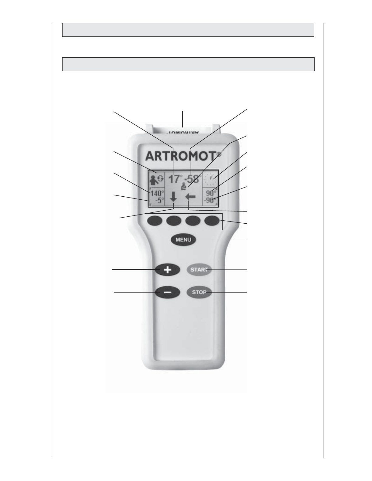
2.3 Description of the programming unit
2.3.1 Programming unit in normal mode
set angle of motor A
selected therapy
protocol
set exion value
set extension value
motor A - selected
direction of motion
+ (plus) key
patient chip card
set angle of motor B
treatment side, left or
right (here: left)
therapy timer
set supination value
set pronation value
motor B - selected
direction of motion
parameter keys
MENU key
START key
- (minus) key
STOP key
52
Page 7
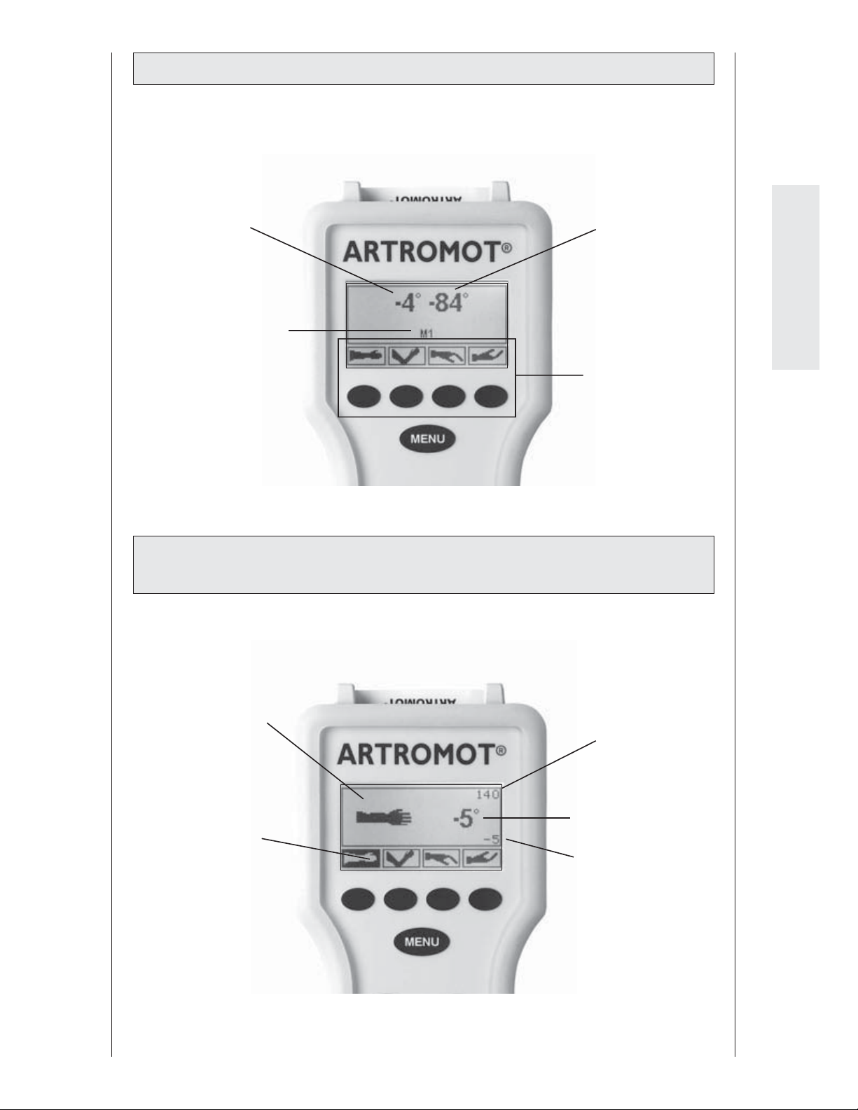
2.3.2 Programming unit in MENU selection mode
set carriage angle for
extension/ exion
selected MENU level
2.3.3 Programming unit in ROM programming mode
(range of motion)
set carriage angle for
pronation/supination
English
selectable parameters and the corresponding selection
keys
selected function
selected parameter
(here: extension)
current maximum
value selected for
exion or supination (here: exion)
set carriage angle for
extension/ exion or
pronation/supination
set maximum extension/pronation value
(here: extension)
53
Page 8
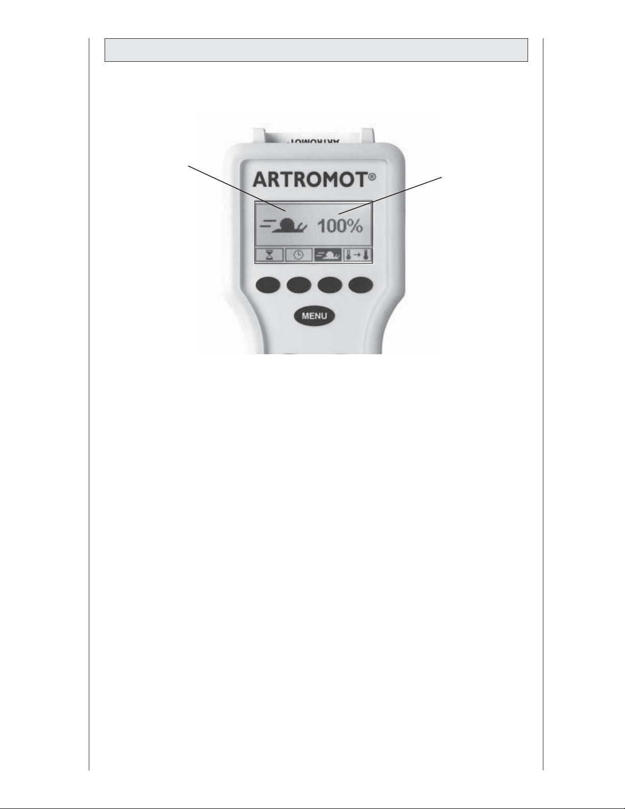
2.2.4 Programming unit in general programming mode
selected functions
status of the selected
function (here speed)
54
Page 9
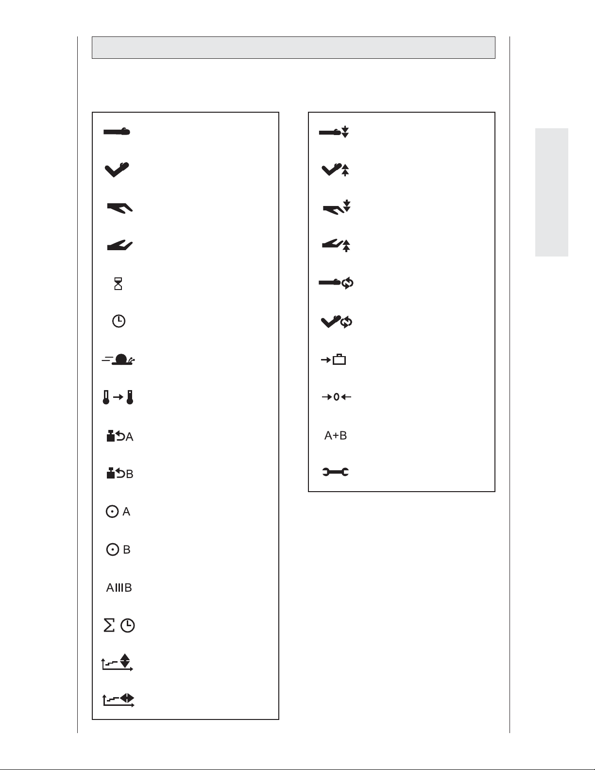
2.4 Explanation of symbols
Also refer to symbol overview on page 266.
extension
exion
pronation
supination
pause
timer
speed
warm-up protocol
stretching in extension
stretching in exion
stretching in pronation
stretching in supination
EROM repeat
extension/pronation
EROM repeat
exion/supination
transport setting
new patient
English
load reversal motor A
load reversal motor B
motor A ON/OFF
motor B ON/OFF
isolation program
total therapy time
extension/ exion
therapy documentation
pronation/supination
therapy documentation
synchronized/non-synchronized mode
service menu
55
Page 10
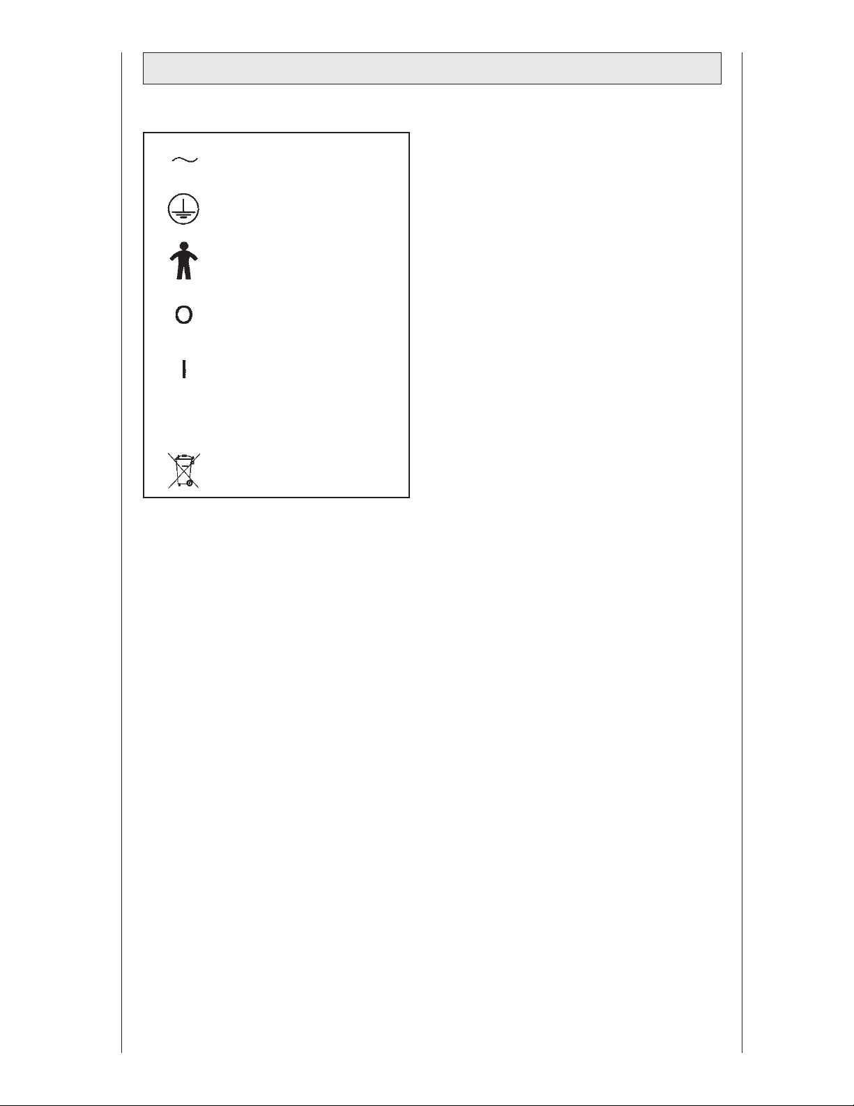
2.5 Explanation of symbols (connections and nameplate)
alternating current
protective earth connection
type B applied part
power switch OFF
power switch ON
Refer to accompanying
documents
Do not dispose with unsorted
municipal waste
56
Page 11
3. Safety information
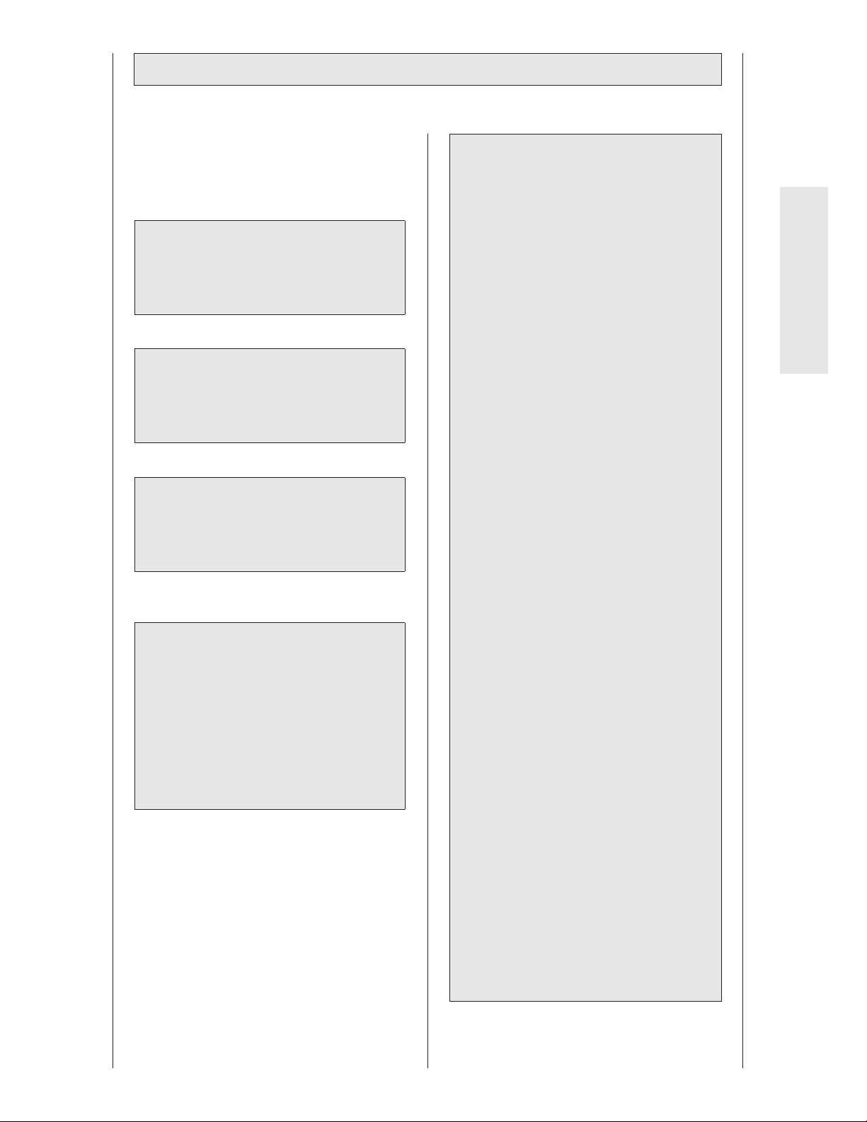
De nitions
Read the safety statements before use of
the CPM device. The safety statements are
classi ed as follows:
Danger!
indicates an imminent hazard. If not
avoided, this hazard will result in death
or serious injury.
Warning!
indicates a hazard. If not avoided, the
hazard can result in death or serious
injury.
Caution!
indicates a potential hazard. If not
avoided, the hazard may result in minor
injury and/or product/property damage.
Warning!
Patient hazard—
− Only authorized individuals are
allowed to operate the
ARTROMOT®-E2/E2 compact. Individuals are authorized after receiving training in the operation of the device and
reading this operation manual.
− Before using the device, the operator
must ascertain that it is in correct
working order and operating condition. In particular, the cables and
connectors must be checked for signs
of damage. Damaged parts must be
replaced immediately, before use.
− Before therapy, a test run consisting of several exercise cycles must
be completed, rst without and then
with the patient. Check that all setting
screws are tightened.
− Stop therapy immediately, when you
have doubts about the device settings
and/or the therapy protocol.
English
Safety information
Danger!
Explosion hazard—
The ARTROMOT®-E2/-E2 compact
is not designed for use in areas of
medical locations where an explosion
hazard may occur. An explosion hazard
may result from the use of ammable
anesthetics, skin cleansing agents and
disinfectants.
− Ensure an anatomically correct
setup of the CPM device suitable for
the patient to be treated. Therefore, carefully verify the following
settings/positions:
(also refer to the numbers on the
device):
1. Horizontal adduction/abduction
(horizontal extension/ exion)
2. Height adjustment
3. Adjustment of the positioning angle
4. Adjustment of the forearm length
5. Axis adjustment motor A and
motor B
6. Backrest adjustment
7. ROM adjustment
− It is not permitted to change the
adjustment of 1 through 6 while the
CPM device is applied on a patient.
57
Page 12

– Movements must not cause any pain
or irritation.
– Patients must be fully conscious
while being instructed in the use of
the CPM device and during therapy.
– The choice of the therapy param-
eters to program and of the therapy
protocols to use is restricted to the
responsible physician or therapist.
It is the physician's or therapist's decision whether or not to use the CPM
device on a speci c patient.
− The patient must be familiar with the
functions of the
ARTROMOT®-E2/-E2 compact programming unit and the unit must
be within easy reach of the patient,
allowing him or her to stop therapy, if
needed. Patients unable to operate
the programming unit, e.g. paralytic
patients, must never be left unattended during therapy.
– Write the patient's name on the
patient chip card. The card should
only be used for this patient.
If the patient chip card is used for
another patient, be sure to delete the
previous patient's data from the
card rst (see sections 4.1 and 5.3,
paragraph "New Patient").
Use original chip cards only.
− All accessories used with the
ARTROMOT®-E2/-E2 compact must be
approved by ORMED.DJO.
– Do not allow parts of the body or
any objects (such as blankets, cushions or cables) to get caught in the
moving parts of the CPM device.
− Always seat the patient on a chair with
four legs and without armrests when
using the ARTROMOT®-E2 compact.
Warning!
Shock hazard—
Strictly observe the following warnings.
Failure to do so endangers the lives of
the patient, the user and other persons
involved.
− Before use allow the
ARTROMOT®-E2/-E2 compact to reach
room temperature. If the device has
been transported at temperatures
below 0 °C (32°F), leave it to dry
at room temperature for about 2
hours, until any condensation has
disappeared.
– The ARTROMOT®-E2/-E2 compact
must only be operated in dry rooms.
− When disconnecting the device from
the power line, remove the plug from
the wall outlet rst, before disconnecting the cable from the device.
− When connecting the device to
other equipment or when creating a
medical system, check that the sum
of leakage currents will not cause any
hazard. Please contact ORMED.DJO, if
you have questions in this matter.
– Do not use multiple portable socket
outlets (MPSO) to connect the device
to the power line. The
ARTROMOT®-E2/-E2 compact must
be connected to a properly installed
wall outlet with a non-fused
earthed wire. Before connecting the
power cord, it must be completely
unrolled and placed such that it will
not get caught in the moving parts of
the device.
– Before cleaning and service interven-
tions, disconnect the device from
the power line by removing the
power cord from the wall outlet.
– Liquids must not be allowed to en-
ter the CPM device or the program-
ming unit. If liquids have entered into
the device, the
ARTROMOT®-E2/-E2 compact must
be checked by a service technician,
before it can be reused.
58
Page 13

Warning!
Caution!
Equipment malfunction—
− Magnetic and electrical elds are
capable of interfering with the proper
performance of the device. For this
reason make sure that all external
devices operated in the vicinity of the
CPM device comply with the relevant
EMC requirements. X-ray equipment, MRI devices, radio systems, cell
phones, etc. are possible sources of
interference as they may emit higher
levels of electromagnetic radiation.
Keep the CPM device away from these
devices and verify its performance
before use.
− Refer repair and maintenance to
authorized persons.
− Route all cables such that they will
not get caught by the moving parts
during operation and that they do not
present a stumbling hazard.
− Inspect the
ARTROMOT®-E2/-E2 compact for damage and loose connections at least
once a year.
Preventing cha ng and pressure sores
— If your patient is adipose, very tall or
very short, be sure to prevent cha ng
and pressure sores.
Patient hazard, damage to the
CPM device — The CPM device
ARTROMOT®-E2 must not be used to
transport people.
Caution!
Equipment damage—
− Check that the voltage and frequency
ratings of your local power line are
those indicated on the nameplate.
− The seat withstands a maximum
continuous loadof 150 kg / 330 lb.
− The arm support element with-
stands a maximum continuous load
of 9 kg / 20 lb.
− Do not allow any objects (such as
blankets, cushions, or cables) to get
caught in the moving parts of the
CPM device.
English
− Do not expose the
ARTROMOT®-E2/-E2 compact to direct
sunlight, because some of the components may reach inadmissibly high
temperatures.
− Be aware that the connectors can only
be inserted in the correct orientation
and secure all connections with the
locks.
59
Page 14
4. Device setup
Note: See device description on pages
2/3 and 268/269.
4.1 Connecting the
ARTROMOT®-E2/-E2 compact,
performance check
1. Connect the power cord to socket (18)
of the device and connect the mains
plug to a wall outlet with a non-fused
earthed wire (100 to 240 Volt, 50/60 Hz).
2. Turn the power switch (19) on.
3. Follow these steps to set the carriage to
the home position:
Initial adjustment for new patients
Write the patient's name down on the back
of the chip card. Insert the original patient
chip card (17) into the programming unit
(15).
Press the MENU key on the programming
unit seven times in rapid succession or
give it one long press to access programming level seven (with each key press, you
advance one level).
Press the "new patient" parameter key
and select this function (a check
mark appears in the circle next to the
function).
Press the START key. The CPM device auto-
matically enters the home position.
Adjustment with
programmed chip card
Insert the original patient chip card (17)
into the programming unit (15).
Press the START key.
The CPM device automatically moves to
the starting position (middle position of
the set extension/ exion and pronation/supination values).
Performance check
If the programming unit can be operated
as described above and the
ARTROMOT®-E2/-E2 compact moves to the
home position (for home position values,
please refer to sections 5.3), the CPM device has passed the performance check.
The device also runs performance checks
regularly during operation. This is what
happens, if a problem is identi ed:
− An audio signal sounds.
− The device switches o immediately.
− The message "ERROR" and an error code
(e.g. ERROR 5) appear on the display.
In this situation, you may attempt to
restart the device by turning it brie y
o and on again with the power switch.
If the error message persists, have the
device inspected by a Service technician,
before using it again.
If it has been determined that the
ARTROMOT®-E2/-E2 compact operates
perfectly, ask the patient to sit down on the
ARTROMOT®-E2/-E2 compact chair.
60
Page 15
4.2 Adjusting the device to the
patient
ARTROMOT®- E2 compact:
positioning the chair and the CPM
device
Note!
For the following adjustments, the
patient's arm should not yet be placed
on the armrest. After you have adjusted
the device to the approximate patient
measurements, the patient can place
his/her arm on the armrest for a check of
the setup and for the ne adjustment.
The settings are numbered 1 through
5. For easy orientation, you will nd the
same numbers on the CPM device. Always set up the CPM device in this order.
Write the settings down on the back of
the patient's chip card.
Before you adjust the
ARTROMOT®-E2/-E2 compact to the
patient, you may have to convert the
device for use on the left or right elbow
joint. (see section 6.4 Conversion)
Before any treatment is possible, adjust the
device as follows:
ARTROMOT®- E2:
backrest, armrest
Before you start setting up the device for
the exercise protocol, you must adjust it to
a position that is anatomically correct for
the respective patient.
• Open thumbscrew (10) and adjust the
backrest to a position that is comfortable
for the patient (Fig. F).
• Set the armrest for the healthy arm to a
height that allows the patient to sit up
straight (locking screw 14).
Before you start setting up the device for
the exercise protocol, you must adjust it to
a position that is anatomically correct for
the respective patient.
• Only use chairs with four legs and without armrests. The patient must be seated
safely and straight on the chair.
• Once you have set up the
ARTROMOT®- E2 compact, lock the
brakes (22) of the castor wheels (25).
4.2.1 Adjusting the
ARTROMOT®-E2 to the
patient
Note: The individual steps are illustrated
on page 4.
@ a,b and c Horizontal Extension/Flex-
ion (Fig. A)
Horizontal adduction/abduction is
set manually. It is the purpose of the adjustment to achieve congruent axes of the
motor axis and the elbow joint.
• To begin with, press knob (1). Leave it
engaged in the open position.
• Now open screw (2). The double joint
now moves freely.
• Set the motion element with motor A to
the appropriate position. Make sure that
a congruence of the axis of motor A and
the elbow joint is achieved.
• Push knob (1) in the opposite direction.
• Tighten screw (2).
English
61
Page 16
; Height adjustment (Fig. B)
Before opening locking screw (4), hold the
moving part of the CPM device by grasping
the double joint (3), to prevent the part
from falling down.
• Open screw (4) and set the motion element to the appropriate height. Ensure
that the entire upper arm lies on the
support (5). The patient should sit up
straight and be relaxed.
• Tighten screw (4).
• Now check the agreement of the axis of
motor A and the elbow joint. If required,
make a ne adjustment of the vertical
orientation, using locking pin (6).
= Adjustment of the positioning angle
(Fig. C)
Caution!
Patient hazard / equipment damage—
Hold motor B for this adjustment to
secure the device.
& Axis adjustment motor B
(Fig. E)
In most cases the setting is 0 on the scale.
In cases of a deformed forearm, the setting
may have to be changed.
• Open the locking screw (13) and perform the adjustment.
• Tighten the locking screw (13).
( Backrest adjustment
(Fig. F)
Set the backrest to the foremost position
before setting the motion element to an
angle of 0° for horizontal adduction/abduction. To do so, open adjusting screw (10),
set the backrest to the foremost position
and tighten the screw.
To achieve optimal congruence between
the axis of motor A and the patient's rotational axis of the elbow joint, the backrest
angle can be individually adjusted in all
other horizontal adduction/abduction
positions.
• Hold the motion element at bracket (30).
• Now open screw (7) and set the appropriate angle.
• Tighten screw (7).
% Adjustment of the forearm length
(Fig. D)
Caution!
Patient hazard / equipment damage—
Hold motor B for this adjustment to
secure the device.
• Open the cam lever (8) and set the
appropriate length. Make sure that the
slider (9) is free to move at least 2 cm in
either direction. There must be enough
space for the ngers between the hand
support and motor B.
Checking the setup, ne adjustment
Please check the following before using the
CPM device on a patient:
• Check settings 1 to 6 and make sure that
the pivot of motor A agrees with the
pivot of the elbow joint, i.e., that the axis
of motor B vertically passes through the
elbow joint.
• Check that all locking screws and clamping levers are tight.
• Tighten the cam lever (8).
62
Page 17
4.2.2 Adjusting the
ARTROMOT®-E2 compact
to the patient
Note:
The individual steps are illustrated on
page 82.
• Open the cam lever (3) and set the
appropriate length. Make sure that the
slider (4) is free to move at least 2 cm in
either direction. There must be enough
space for the ngers between the hand
support and motor B.
• Tighten the cam lever (3).
Note:
Step 1 does not exist for the
ARTROMOT®-E2 compact.
; Height adjustment (Fig. A)
Before opening locking screw (1), hold the
moving part of the CPM device by grasping
motor A (11), to prevent the part from falling down.
• Open screw (1) and set the motion element to the appropriate height. Ensure
that the entire upper arm lies on the
support (20). The patient should sit up
straight and be relaxed.
• Tighten screw (1).
• Now check the agreement of the axis of
motor A and the elbow joint. If required,
make a ne adjustment of the vertical
orientation, using locking pin (26).
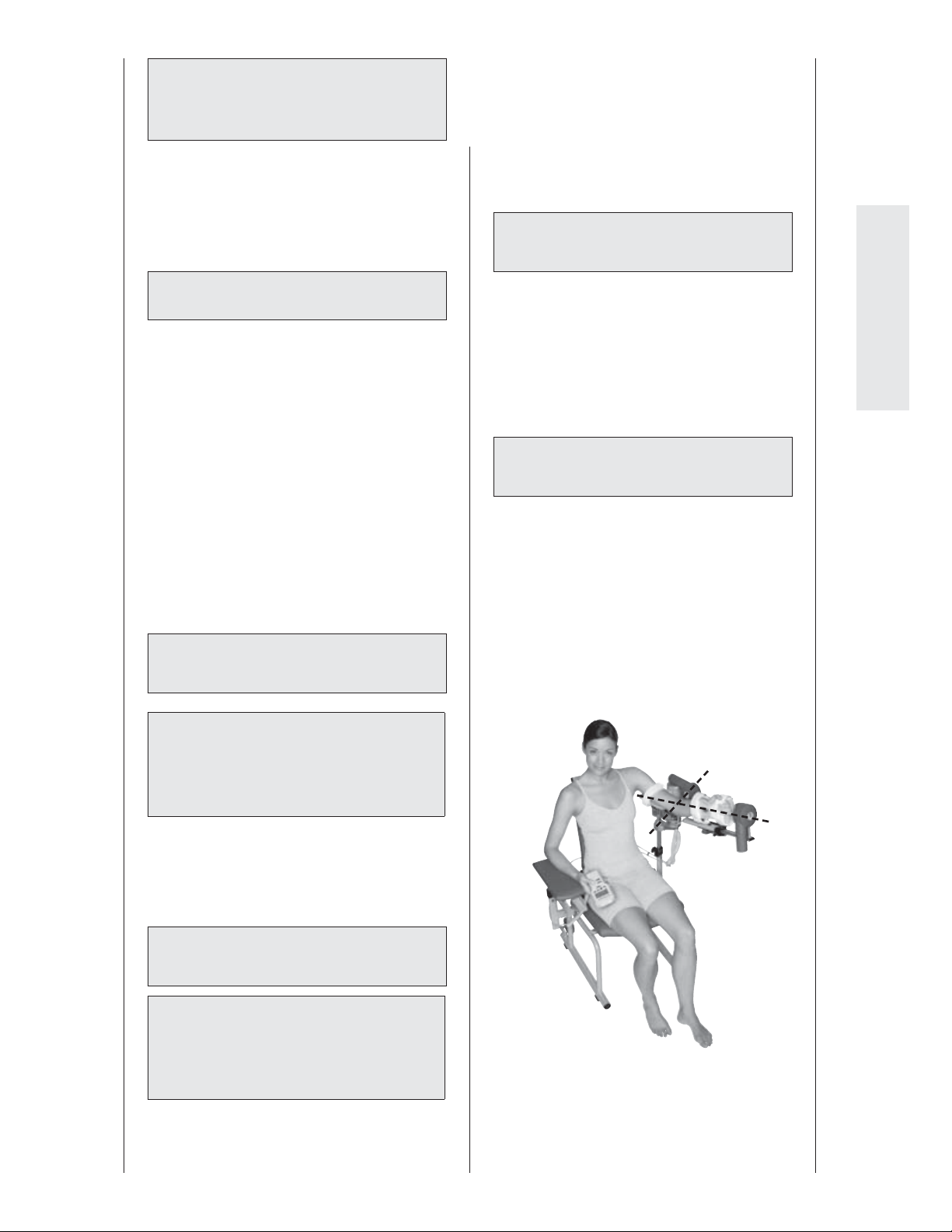
= Adjustment of the positioning angle
(Fig. B).
& Axis adjustment motor B
(Fig. D)
In most cases the setting is 0 on the scale.
In cases of a deformed forearm, the setting
may have to be changed.
• Open the locking screw (7) and perform
the adjustment.
• Tighten the locking screw (7).
Checking the setup, ne adjustment
Please check the following before using the
CPM device on a patient:
• Check settings 2 to 5 and make sure that
the pivot of motor A agrees with the
pivot of the elbow joint, i.e., that the axis
of motor B vertically passes through the
elbow joint.
• Check that all locking screws and clamping levers are tight.
English
Caution!
Patient hazard / equipment damage—
Hold motor B for this adjustment to
secure the device.
• Hold the motion element at bracket (27).
• Now open screw (2) and set the appropriate angle.
• Tighten screw (2).
% Adjustment of the forearm length
(Fig. C)
Caution!
Patient hazard / equipment damage—
Hold motor B for this adjustment to
secure the device.
63
Page 18

5. Setting the treatment values
Warning!
Patient hazard—
Before therapy, a test run consisting
of several exercise cycles must be completed without the patient. Then repeat
the test run with the patient and check
that the movement does not cause any
pain.
Note: See also 2.2 and 2.3
Note!
Programming is only possible when the
patient's chip card has been inserted.
For information about therapy parameters and programming of special functions, please refer to sections 5.1 to 5.3.
See section 5.4 for programming
examples.
2. If a "Tex t " programming unit is operating with a formatted "Graphics" chip
card
− the selected language automati-
cally changes to the default setting:
German.
− the reverse on load setting saved
for motor A in the "Graphics" version is automatically used for both
motors.
− a key lock set in the "Graphics" ver-
sion will remain active, only when
no changes were made with the
"Text" version; the key lock function
is not an option with the "Text"
version.
5.1 General information on
Important!
The programming unit
ARTROMOT
ics" can be connected to all products of
the ARTROMOT
machines.
It is possible to exchange chip cards
between the "Text" and "Graphics"
versions.
Please note:
1. If a "Graphics" programming unit is
operating with a formatted "Text"
chip card
− the selected language of the
"Text" version remains activated;
it is irrelevant for the "Graphics"
version.
− the reverse on load setting saved
in the "Text" version is automatically used for both motors.
− the key lock is disabled.
®
-E2/-E2 compact "Graph-
®
family of elbow CPM
programming the
®
ARTROMOT
-E2/
-E2 compact
1. You activate the programming mode by
brie y pressing the MENU key on the
programming unit.
2. The treatment parameters and functions
are allocated to seven programming
levels (four functions per level).
To be able to program a parameter you
will have to access the corresponding
programming level. This is also done
with the MENU key. With each brief key
press you advance one level. The code
M1, M2, etc. that appears in the middle
of the display indicates the programming level. To back up one level, e.g.
from level 2 to 1 or from level 1 to 7, hold
the MENU key down for some seconds.
64
Page 19
3. You activate the treatment parameters
and functions with the four parameter
keys below the display. The symbols
above the four parameter keys indicate
the assigned parameters and functions.
This is what happens when you press
one of the parameter keys to select a
parameter:
• The corresponding symbol appears
on the display in a larger format.
• The set value is displayed.
• The symbol above the parameter key
appears in reverse video.
4. With the + / - keys (plus/minus) you
change the displayed value. When you
press and hold the key, the value will
change at a higher rate.
Some of the (special) functions can only
be enabled and disabled. This is done by
pressing the corresponding parameter
key or with the + / - keys. Active parameters are identi ed with a check mark in
the circle next to the symbol.
5. Having programmed all parameters,
press the STOP key to save the values.
Note!
− Refer to section 5.3 for a description
of the parameters.
− To view the set parameter values,
press the corresponding parameter
key. Before, however, you have to
press the STOP key and access the
correct menu level.
− To prevent accidental changes of the
parameter settings, you can lock the
keys. To do so, simultaneously press
keys + and – for approx. 3 seconds.
English
Press both keys again for approx. 3
seconds to unlock.
− Selecting the "new patient" function will
automatically delete the data on the patient chip card. When you have nished
programming the unit and press the
STOP key, the settings will automatically also be saved to the patient chip
card.
6. Then press the START key: the
ARTROMOT®-E2/-E2 compact checks the
set values, moves to the position halfway
between the set extension and exion
values as well as to the set supination
and pronation values and stops.
7. Press the START key again to start
therapy.
The CPM device will now begin with the
set physiological motion pattern in the
synchronized mode. The motor with
the larger range of motion operates at
the programmed speed, while the speed
of the second motor is adapted. This
ensures that both motors will reach their
target positions at almost the same time.
After activation of the START key in the
non-synchronized mode the motors
will perform random movements, each
motor reversing after reaching the maximum values. The programmed speed is
valid for both motors.
− Emergency stop function: When any of
the keys is pressed during therapy, the
ARTROMOT
immediately o .
– When the START key is pressed again
in the synchronized mode and in the
non-synchronized mode, the carriage
will reverse its direction.
Patients with a
programmed chip card
• First complete the mechanical
adjustments.
• Then insert the chip card (the patient is
not yet positioned on the CPM device).
• Press the START key: the device will
move to the starting position as speci ed by the parameters stored on the
chip card and stops.
• Position the patient on the CPM device
and press the START key to initiate
therapy.
®
-E2/-E2 compact switches
65
Page 20
5.2 Programming the
®
ARTROMOT
-E2/
-E2 compact
Di erent programming levels are provided
to program the
ARTROMOT
You change between levels by pressing the
MENU key repeatedly.
®
-E2/-E2 compact.
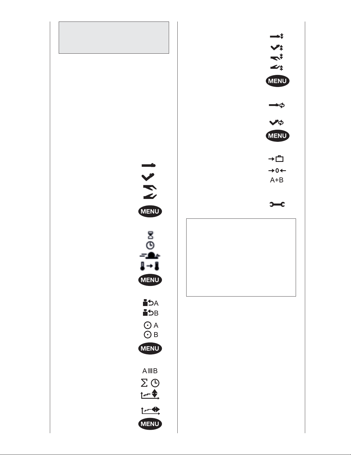
LEVEL 5:
- stretching in extension
- stretching in exion
- stretching in pronation
- stretching in supination
LEVEL 6:
The currently selected level is indicated on
the display.
The following treatment values, settings
and information can be entered/viewed
on the programming unit (15):
LEVEL 1:
- extension
- exion
- pronation
- supination
LEVEL 2:
- pause
- therapy timer
- speed
- warm-up protocol
LEVEL 3:
- EROM repeat
extension/ pronation
- EROM repeat
exion/supination
LEVEL 7:
- transport setting
- new patient
- operating mode
synchronized/
non-synchronized
- Service menu
Note!
• While you adjust the values, the
carriage will move to the set range.
This allows you to easily and quickly
determine the ROM where the patient
does not experience any pain.
• The angle entered last for the respec-
tive directions of motion will be saved
in each case.
- reverse on load - motor A
- reverse on load - motor B
- motor A ON/OFF
- motor B ON/OFF
LEVEL 4:
- isolation protocol
- total therapy time
- therapy documentation:
extension/ exion
- therapy documentation:
pronation/supination
66
Page 21
5.3 Therapy parameter details
• To access the programming level you
need, repeatedly press the MENU key.
• The treatment parameters are selected
with the di erent parameter keys.
• To change the treatment values, press
the + / – keys.
• To enable/disable a function, press the
respective parameter key again.
• To save the entered values, press the
STOP key.
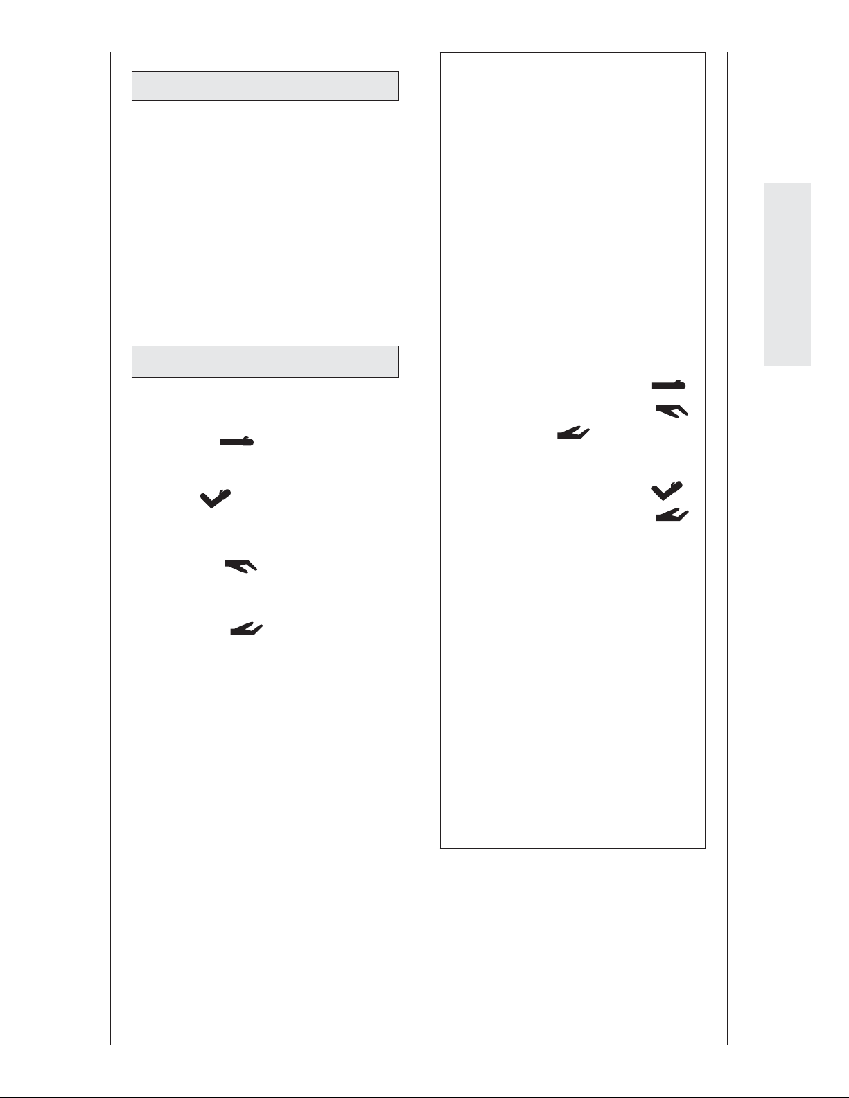
LEVEL 1:
Note!
• The programmed values and the
values (degrees) measured on the
patient may deviate slightly.
• To ensure a physiological motion, the
carriage simultaneously moves to the
following positions in the synchronized mode:
− maximum extension value and
maximum pronation value
− maximum exion value and maxi-
mum supination value.
• To ensure that the movements you
program are physiological in nature,
we recommend to program the carriage in the following order:
1. maximum extension value
2. maximum pronation value
English
■ extension
maximum value: - 5 degrees
■ exion
maximum value: 140 degrees
■ pronation
maximum value: - 90 degrees
■ supination
maximum value: 90 degrees
3. supination = 0°
(to relieve the elbow)
4. maximum exion value
5. maximum supination value
• When the START key is pressed in
the synchronized mode, the carriage
will rst move to the position halfway
between the set maximum extension/
exion values as well as the pronation/supination values. The carriage
will stop in this position. Treatment
begins when you press the START
key again.
• Horizontal adduction/abduction is
adjusted manually. These are possible
settings:
horizontal adduction : 120°
horizontal abduction: 0°
67
Page 22
LEVEL 2:
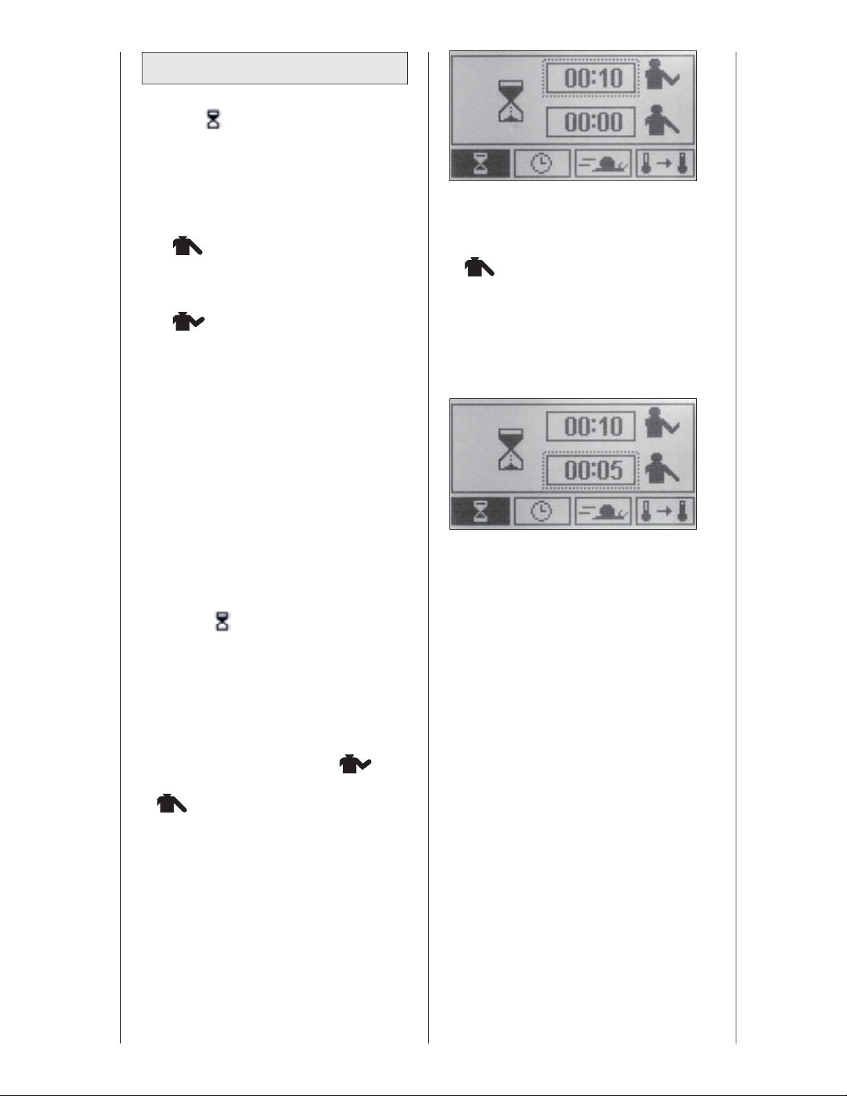
■ Pauses
Pauses occur at each programmed maxi-
mum value.
These are the two pause points:
− maximum extension value and maximum pronation value
− maximum exion value and maximum supination value.
Pauses are separately adjustable for
motor A and motor B between 1 second
and 60 minutes. Pauses can be set in
steps of 1 second to any value between
0 and 59 seconds, and in steps of 1
minute to any value between 1 and 60
minutes.
• Press the parameter key again when
done. The frame automatically moves to
the line below, indicating that the extension/pronation pause can be adjusted
.
The parameter key is only used to
toggle between these two functions.
• To modify the value, press the "+" (plus)
or "-" (minus) key.
Select a duration of 5 seconds, for
instance.
Default: no pause
Follow these steps to program pauses:
• Access menu level 2, then press the
parameter key to select the special
function
.
• The display shows the symbol for the
special function and the selected pause
durations.
The display shows the symbol for the
special function and the selected pause
durations.
top: exion/supination pause
.
bottom: extension/pronation pause
.
The exion/supination pause duration
appears in a box.
• To change the exion/supination pause,
press the "+" or "-" key.
• Save the programmed values by pressing the STOP key, then press the START
key to initiate the treatment.
Select a duration of 10 seconds, for
instance.
68
Page 23
■ Therapy timer
Default setting is continuous opera-
tion.
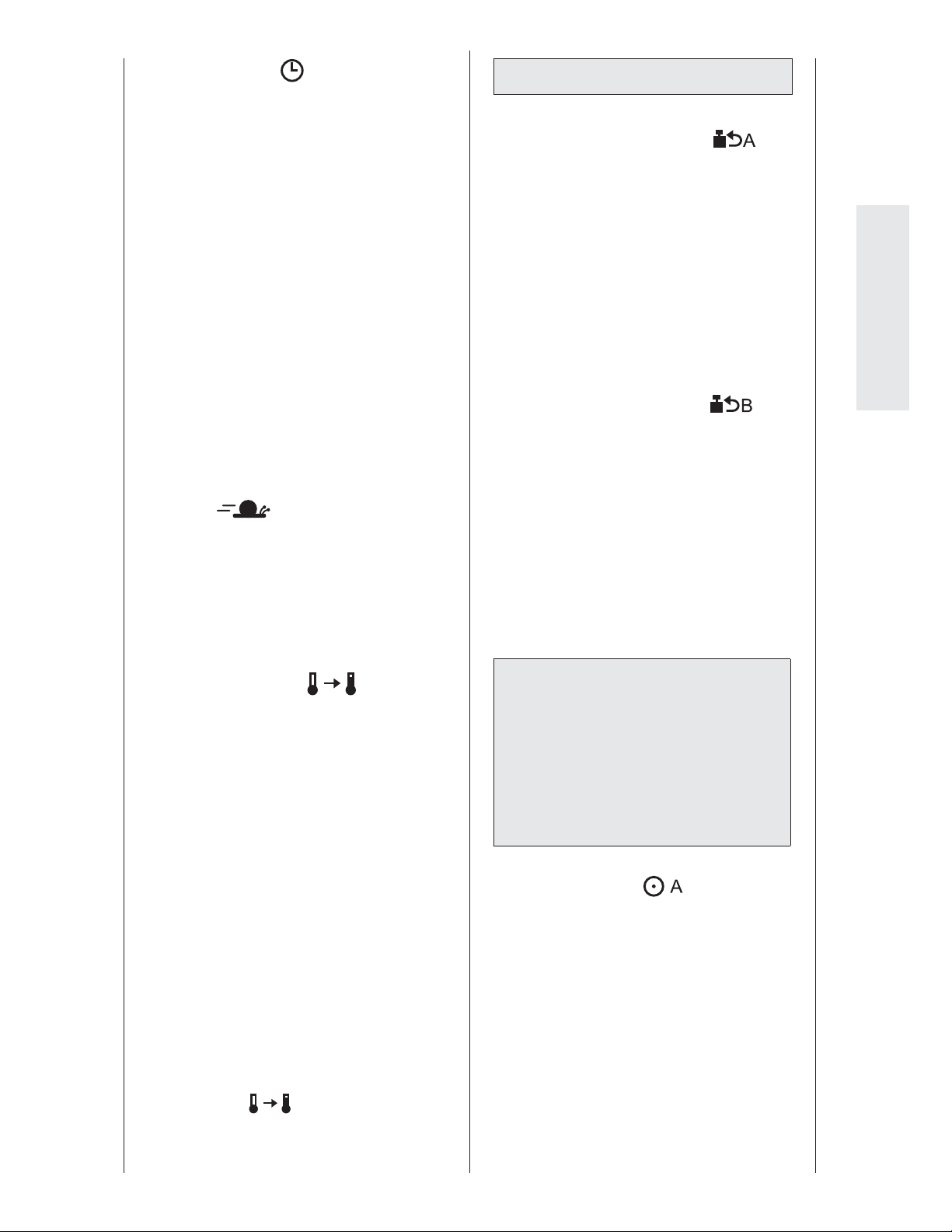
A clock symbol in the upper right-hand
corner of the display identi es the con-
tinuous mode of operation. The clock
indicates the elapsed therapy time.
In the continuous mode, the device
must be stopped with the STOP key.
However, the therapy timer can be
set in steps of 1 minute to any value
between 1 and 59 minutes and in
steps of 30 minutes to any value
between 1 and 24 hours. When the
time has elapsed, the device switches
automatically o and stops in the middle
between the set limit values.
In this case, a circle replaces the clock
symbol. The circle lls as the therapy
time progresses.
■ Speed
The speed can be adjusted between 1 %
and 100 % in steps of 1 %.
1 % is equivalent to 14°/minute
100 % is equivalent to 230°/minute
Default: 100 %
LEVEL 3:
■ Reverse on load - motor A
(safety feature)
The device automatically reverses both
motors when the patient's resistance
(load) exceeds the set value.
Adjustable levels for reverse on load fea-
ture: 1 - 25. At level 1, very low resistance
will cause the device to reverse; at level
25, a high resistance is required to initiate the reversal.
Default: level 25
■ Reverse on load - motor B
(safety setting)
The device automatically reverses both
motors when the patient's resistance
(load) exceeds the set value.
Adjustable levels for reverse on load
feature: 1 - 25.
At level 1, very low resistance will cause
the device to reverse; at level 25, a high
resistance is required to initiate the
reversal.
Default: level 25
English
■ Warm-up protocol
During warm-up, the patient will
slowly become used to the set maximum values for extension/ exion and
pronation/supination.
The warm-up protocol starts in the
middle between the two maximum
values set for extension/ exion and
pronation/supination. The range of
motion increases with each cycle, until
the programmed maximum values are
reached after a total of 15 cycles.
After reaching the maximum values, the
device automatically enters the normal
mode.
If a therapy time is activated, the system
restarts with the warm-up protocol
when the therapy time has elapsed and
the devices is started again.
During warm-up, the display will show
the symbol
hand corner.
in the upper, left-
Caution!
Patient hazard—
The reverse on load feature is a safety
measure to protect the patient in the
event of cramps, spasms, locked joints
and similar situations. The manufacturer
cannot be held liable for misuse of this
feature.
■ Motor A ON/OFF
To permit fully isolated movements, the
motors can individually be turned on
and o . Motor A e ects the extension
and exion movements, while motor
B e ects the pronation and supination
movements.
For an isolated pronation/supination
movement, set motor A to the appropriate position (extension/ exion), then
turn the motor o .
Default: disabled
69
Page 24
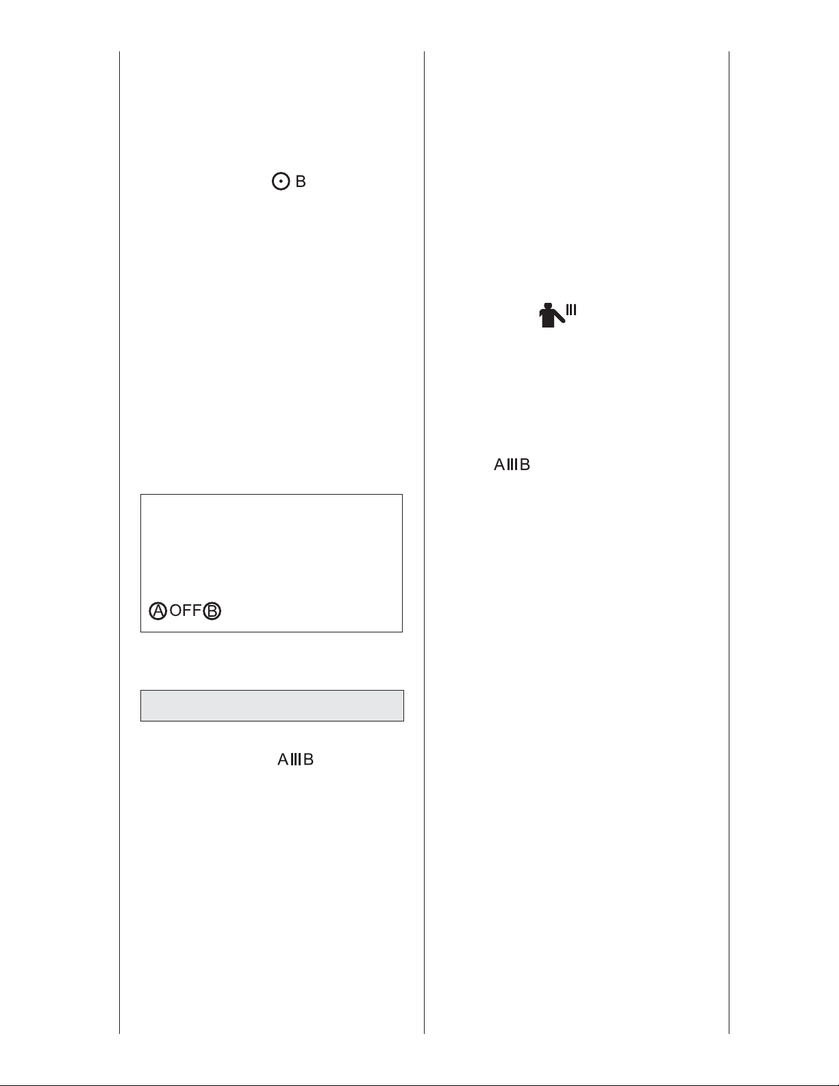
In normal mode the display indicates the
symbol "OFF" during therapy
of the programmed extension/ exion
angles.
Default: motor A ON
■ Motor B ON/OFF
To permit fully isolated movements, the
motors can individually be turned on
and o . Motor A e ects the extension
and exion movements, while motor
B e ects the pronation and supination
movements.
For an isolated extension/ exion move-
ment, set motor B to the appropriate
position (pronation/supination), then
turn the motor o .
, instead
motor B is operating (symbol for motor
A: OFF)
• The stop position at the end of the last
cycle (for both extension/ exion and
pronation/supination) can be selected
in steps of 25% between 0% and 100%
of the programmed maximum range of
motion.
• Steps 1 and 2 can be repeated as often
as needed. You can stop treatment
with the STOP key; after the programmed therapy duration, it will stop
automatically.
During warm-up, the display will show
the symbol
hand corner.
Default: disabled
in the upper, left-
In normal mode the display indicates the
symbol "OFF" during therapy, instead of
the programmed pronation/supination
angles.
Default: motor B ON
Note!
Please note that one motor (A or B) must
always be turned on. Otherwise the
following symbol will be displayed when
you press START:
LEVEL 4:
■ Isolation protocol
For this special function, both motors
are turned on, but they will never move
simultaneously.
These are the steps of the function:
• To begin with, motor A moves to the
programmed maximum values for
extension and exion for three cycles
and then stops. In this phase, motor B is
disabled (symbol for motor B: OFF)
Follow these steps to program the special
function:
• Access menu level 4, then press the
parameter key to select the special function
The display will indicate:
- the symbol representing the special
function
- the status of the special function (circle
with or without check mark)
- two boxes with the current percentage
of the stop positions for motor A and B
- a check mark in a circle.
• You activate the function with the "+"
key and deactivate it with the "-" key.
In this case it is not possible to activate/
deactive the function by pressing the
parameter key again.
A check mark in the circle identi es the
activated function.
• Next press the parameter key of the
isolation protocol. The marking moves
to the upper percentage value, allowing
you to enter the stop position for
motor A.
• To modify the value, press the "+" (plus)
or "-" (minus) key.
Select 75%, for instance.
.
• Then motor B will move to the programmed maximum values for pronation and supination for one cycle and
stops, then the full cycle will start over
with motor A. Motor A is disabled while
• Press the parameter key again when
done. The marking automatically moves
to the lower box, allowing you to adjust
the stop position of motor B.
70
Page 25
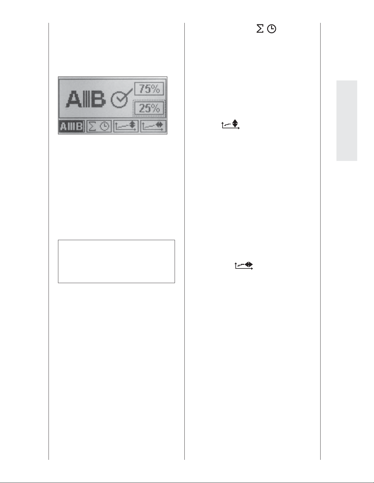
• To modify the value, press the "+" (plus)
or "-" (minus) key.
Select 25%, for instance.
• Save the programmed values by pressing the STOP key, then press the START
key to begin the treatment.
This is what happens:
Extension/ exion is treated three times rst
(motor A). Motor B is positioned at 25%
of the programmed range of motion for
pronation and supination.
Subsequently, pronation/supination is
treated once (motor B). Motor A is positioned at 75% of the programmed range of
motion for extension and exion.
■ Total therapy time
Under menu item "total therapy time"
you can view each patient's total therapy
time (duration of all the patient's therapy
sessions).
Deleting the stored therapy time:
Press and hold the parameter key for
5 seconds or select the "new patient"
function.
■ Extension/ exion therapy documen-
tation
This is a special function of the
ARTROMOT®-E2/-E2 compact which
allows the entire therapy documentation
to be represented.
The carriage run times as well as the
range of motion of the sessions are
recorded.
The collected data are presented graphi-
cally in the form of a coordinate system
(X-axis = range of motion / Y-axis = time)
where the upper curve illustrates the
trend of the exion movement and the
lower curve the trend of the extension
movement.
English
Note!
The percentage values can be modi ed only when the special function is
enabled (check mark).
■ Pronation/supination therapy docu-
mentation
This is a special function of the
ARTROMOT®-E2/-E2 compact which
allows the entire therapy documentation
to be represented.
The carriage run times as well as the
range of motion of the sessions are
recorded.
The collected data are presented graphi-
cally in the form of a coordinate system
(X-axis = range of motion / Y-axis = time)
where the upper curve illustrates the
trend of the supination movement and
the lower curve the trend of the pronation movement.
71
Page 26
LEVEL 5:
■ Stretching in extension
With the special "stretching in exten-
sion" function the joint will be gently
stretched (arm stretching movement).
Only the extension/ exion movement
is treated here. Motor B is automatically
disabled. The position of motor B cannot
be changed once this special function
has been activated.
Starting at the middle position the
carriage will rst move to the programmed exion limit and then to the
programmed extension limit.
Subsequently the carriage reverses 5 °
towards exion and then moves very
slowly back to the programmed extension value (symbol:
the carriage attempts to attain another 5
° at an even slower speed (symbol:
If a high resistance toward the additional
5 ° is sensed, the reverse on load function is automatically activated and the
carriage moves in the opposite direction.
This stretch cycle is repeated ten times.
). Subsequently
).
Note!
• If a pause has been programmed, the
carriage will stop for the pause each
time the maximum stretching value is
attained.
• Enabling the stretching in extension
function automatically disables motor
B. The only movement performed is
extension/ exion.
• It is not possible to combine a second
stretching function with the special
function "stretching in extension".
• During operation, the display will
show the symbol
left-hand corner.
■ Stretching in exion
With the special "stretching in ex-
ion" function the joint will be gently
stretched (arm bending movement).
Only the extension/ exion movement
is treated here. Motor B is automatically
disabled. The position of motor B cannot
be changed once this special function
has been activated.
in the upper,
After that the carriage moves to the
programmed exion limit and restarts
the stretching in extension cycle.
This sequence can be repeated
as often as needed. You can stop
treatment with the STOP key; after the
programmed therapy duration, it will
stop automatically.
Default: disabled
Starting at the middle position the car-
riage will rst move to the programmed
extension limit and then to the programmed exion limit.
Subsequently the carriage reverses 5 °
towards extension and then moves very
slowly back to the programmed exion
value (symbol:
attempts to attain another 5 ° at an even
slower speed (symbol:
If a high resistance toward the additional
5 ° is sensed, the reverse on load function is automatically activated and the
carriage moves in the opposite direction.
This stretch cycle is repeated ten times.
After that the carriage moves to the pro-
grammed extension limit and restarts
the stretching in exion cycle.
This sequence can be repeated
as often as needed. You can stop
treatment with the STOP key; after the
programmed therapy duration, it will
stop automatically.
). Then the carriage
).
Default: disabled
72
Page 27
Note!
Note!
• If a pause has been programmed, the
carriage will stop for the pause each
time the maximum stretching value is
attained.
• Enabling the stretching in exion
function automatically disables motor
B. The only movement performed is
extension/ exion.
• It is not possible to combine a second
stretching function with the special
function "stretching in extension".
• During operation, the display will
show the symbol
left-hand corner.
■ Stretching in pronation
With the special "stretching in prona-
tion" function the joint will be gently
stretched in the pronation direction.
Only the pronation/supination movement is treated here. Motor A is automatically disabled. The position of motor
A cannot be changed once this special
function has been activated.
in the upper,
• If a pause has been programmed, the
carriage will stop for the pause each
time the maximum stretching value is
attained.
• Enabling the stretching in pronation
function automatically disables motor
A. The only movement performed is
pronation/supination.
• It is not possible to combine a second
stretching function with the special
function "stretching in pronation".
• During operation, the display will
show the symbol
left-hand corner.
■ Stretching in supination
With the special "stretching in supina-
tion" function the joint will be gently
stretched in the supination direction.
Only the pronation/supination movement is treated here. Motor A is automatically disabled. The position of motor
A cannot be changed once this special
function has been activated.
in the upper,
English
Starting at the middle position the car-
riage will rst move to the programmed
supination position and then to the
programmed pronation position.
Subsequently the carriage reverses 5 °
towards supination and then moves very
slowly back to the programmed pronation value (symbol:
the carriage attempts to attain another 5
° at an even slower speed (symbol:
If a high resistance toward the additional
5 ° is sensed, the reverse on load function is automatically activated and the
carriage moves in the opposite direction.
This stretch cycle is repeated ten times.
After that the carriage moves to the pro-
grammed maximum supination position
and restarts the stretching in pronation
cycle.
This sequence can be repeated as often
as needed. You can stop treatment
with the STOP key; after the programmed therapy duration, it will stop
automatically.
). Subsequently
).
Starting at the middle position the car-
riage will rst move to the programmed
pronation position and then to the
programmed supination position.
Subsequently the carriage reverses 5 °
towards pronation and then moves very
slowly back to the programmed supination value (symbol:
the carriage attempts to attain another 5
° at an even slower speed (symbol:
If a high resistance toward the additional
5 ° is sensed, the reverse on load function is automatically activated and the
carriage moves in the opposite direction.
This stretch cycle is repeated ten times.
After that the carriage moves to the pro-
grammed maximum pronation position
and restarts the stretching in supination
cycle.
This sequence can be repeated as often
as needed. You can stop treatment
with the STOP key; after the programmed therapy duration, it will stop
automatically.
). Subsequently
).
Default: disabled
Default: disabled
73
Page 28
Note!
• If a pause has been programmed, the
carriage will stop for the pause each
time the maximum stretching value is
attained.
• Enabling the stretching in supination
function automatically disables motor
A. The only movement performed is
pronation/supination.
• It is not possible to combine a second
stretching function with the special
function "stretching in supination".
• During operation, the display will
show the symbol
left-hand corner.
LEVEL 6:
■ EROM repeat
extension/pronation
The special "EROM repeat extension/pro-
nation" function allows a more e cient
exercise in the last 10 ° before the set
maximum extension and pronation
values.
For this protocol, the CPM device starts
in the middle between the set maximum
extension/ exion and pronation/supination values. First of all the carriage moves
simultaneously to the maximum exion
angle and to the maximum supination
angle. Then it moves simultaneously to
the maximum extension angle and to
the maximum pronation angle.
When the set extension/pronation value
has been reached, the carriage reverses
10 ° toward exion/supination and then
moves back again to the maximum extension/pronation angle. The movement
through the nal 10 ° is repeated ve
times at a slow speed.
in the upper,
This sequence can be repeated as often
as needed. You can stop treatment
with the STOP key; after the programmed therapy duration, it will stop
automatically.
Default: disabled
■ EROM repeat
exion/supination
The special "EROM repeat exion/supi-
nation" function allows a more e cient
exercise in the last 10 ° before the set
maximum exion and supination values.
For this protocol, the CPM device starts
in the middle between the set maximum
extension/ exion and pronation/supination values. First of all the carriage
moves simultaneously to the maximum
extension angle and to the maximum
pronation angle. Then it moves simultaneously to the maximum exion angle
and to the maximum supination angle.
When the exion/supination value has
been reached, the carriage reverses 10 °
toward extension/pronation and then
moves back again to the maximum
exion/supination angle. The movement
through the nal 10 ° is repeated ve
times at a slow speed.
At the end of the cycle, the carriage will
again move to the maximum extension
value, at the same time as the maximum
pronation value, and then starts another
cycle with ve repetitions through the
last 10 ° of exion/supination.
This sequence can be repeated as often
as needed. You can stop treatment
with the STOP key; after the programmed therapy duration, it will stop
automatically.
Default: disabled
At the end of the cycle, the carriage will
again move to the maximum exion
value, at the same time as the maximum
supination value, and then starts another cycle with ve repetitions through
the last 10 ° of extension/pronation.
74
Page 29
LEVEL 7:
■ Transport setting
With this function, the carriage will move
to a position optimally suited for packing the CPM device. Select the function
and press the START key. The carriage
moves to the transport position. In the
top left-hand corner of the display you
will see
Transport).
■ New patient
With this function, the CPM device will
move to the home position.
• Select the function and press
the START key:
- The carriage moves to the home
position.
- The programmed treatment param-
eters are deleted.
- All values stored on the chip card are
deleted.
- The carriage stops in the middle
position of the extension/ exion and
pronation/supination angles.
The "new patient" function (home posi-
tion) selects the following settings:
• extension: 25°
• exion: 35°
• pronation: -5°
(also refer to chapter 6
■ Operating mode
synchronized/non-synchronized
Motors A and B can run in synchronized
or non-synchronized mode.
synchronized:
Motors A and B perform a synchronized
movement according to the elbow
joint's physiological motion pattern:
Starting at the middle position of the
set extension/ exion and pronation/
supination angles, the carriage rst
moves simultaneously to the maximum
extension value and the maximum
pronation value. Afterwards it moves
simultaneously to the maximum exion
and maximum supination values. After
reaching this position, the cycle restarts:
maximum extension and maximum
pronation.
During operation the synchronized
mode is indicated in the top left-hand
corner by the symbol
non-synchronized:
Both motors run independently of each
other within the selected ranges of
motion.
To enable the non-synchronized mode,
disable the synchronized mode.
During operation the non-synchronized
mode is indicated in the top left-hand
corner by the symbol
Default: synchronized mode enabled
.
.
English
• supination: 5°
• pauses: 0
• timer: continuous operation
• speed: 100 %
• reverse on load motor A: 25
• reverse on load motor B: 25
• motor A: ON
• motor B: ON
• synchronized mode: ON
• total therapy time: 0
• special functions: disabled
Caution!
Patient hazard—
The synchronized operation is recommended as a general rule. However,
medical and/or therapeutic indications
may call for the non-synchronized mode.
In the non-synchronized mode, particular caution and attention on the part of
the physician/therapist is required to
rule out any risk for the patient.
75
Page 30
■ Service MENU
For service purposes only, refer to Ser-
vice Manual.
Reminder:
set the carriage to the starting position with the START key and initiate
therapy by pressing the START key
again.
You save the selected parameter values by
pressing the STOPkey.
5.4 Application and programming examples
5.4.1 Isolated extension/
exion
1. Complete the mechanical settings and
adjust the carriage to the patient as
described in section 4.2.
2. Press the MENU key on the program-
ming unit to access level 1 (M1).
3. Press the pronation (
tion parameter key (
the + / - keys to set the carriage to the
appropriate rotation position to be
maintained during the isolated extension/ exion movements.
4. Next set the desired range of motion
for extension/ exion by rst pressing
the extension parameter key (
then set the values with the + / - keys.
5. Set the exion value (
same way.
) or supina-
), the press
),
) in the
Note!
• For an exclusive extension/ exion
protocol, motor B for the rotation
movement must be turned o as
described in steps 6 through 8 below.
• Having programmed the ranges of
motion, you can program additional
options, such as pause or speed.
6. Press the MENU key on the program-
ming unit to access level 3 (M3).
7. Press the Motor B ON/OFF parameter
key (
8. Deactivate motor B by pressing the
parameter key Motor B ON/OFF again
or the – (minus) key. The check mark
in the circle next to the symbol must
have disappeared.
9. Save the settings with the STOP key,
) to activate the parameter.
5.4.2 Isolated pronation/
supination
1. Complete the mechanical settings and
adjust the carriage to the patient as
described in section 4.2.
2. Press the MENU key on the program-
ming unit to access level 1 (M1).
3. Activate the parameter key
extension (
then press the + / - keys to set the
carriage to the appropriate position
to be maintained during the isolated
pronation/supination movements.
4. Next set the desired range of motion
for pronation/supination by rst pressing the pronation parameter key
(
), then set the values with the
+ / – keys.
5. Set the supination value (
same way.
) or exion ( ),
) in the
Note!
• For an exclusive rotation protocol,
motor A for extension/ exion must
be turned o as described in steps 6
through 8 below.
• Having programmed the ranges of
motion, you can program additional
options, such as pause or speed.
6. Press the MENU key on the program-
ming unit to access level 3 (M3).
7. Press the Motor A ON/OFF parameter
key (
8. Deactivate motor A by pressing the
parameter key Motor A ON/OFF again
or the – (minus) key. The check mark
in the circle next to the symbol must
have disappeared.
9. Save the settings with the STOP key,
set the carriage to the starting position with the START key and initiate
therapy by pressing the START key
again.
) to activate the parameter.
76
Page 31

6. Care, Maintenance, Transport, Conversion
6.1 Care
Warning!
Shock hazard – Unplug the device from
the power line before cleaning.
Shock hazard, equipment damage
– Liquids must not enter the device or
the programming unit.
• The ARTROMOT
be disinfected by wiping down with a
disinfectant. Thus, it complies with the
special hygiene standards for medical
technical equipment.
• The enclosure and removable sup-
port assemblies can be cleaned with
commonly used disinfectants and mild
household detergents.
• Only use a damp cloth to wipe the CPM
device down.
®
-E2/-E2 compact can
Caution!
Equipment damage –
− The plastic material used is not
resistant to mineral acids, formic acid,
phenols, cresols, oxidants and strong
organic or inorganic acids with a pH
value below 4.
6.2 Maintenance (fuse replacement)
Check before each use
Visually inspect the device for signs of
mechanical damage before each use.
If you detect damage or malfunctions that
may impair the safety of the patient or
of the operator, have the device repaired
before using it.
Technical inspections
For safety, the devices require regular
maintenance. To maintain the functional
and operational safety, check all components for damage and loose connections at
least once a year.
These checks should be performed by
persons with adequate training and experience. Damaged and worn parts must immediately be replaced with original spare
parts by authorized sta .
The inspections can be carried out by
ORMED.DJO Technical Service within the
framework of a service agreement.
English
− Use only clear disinfectants to prevent
discoloration of the device.
− Do not expose the CPM device to
strong ultraviolet radiation (sunlight)
and re.
The device does not require additional
regular maintenance.
77
Page 32
Fuse replacement
Warning!
Patient hazard, equipment malfunction
and damage—
The replacement of fuses must be
referred to specialists as de ned in IEC
60364 or other applicable standards
(e.g. biomedical technicians, electricians,
electronics installers).
Fuses used must be T1A fuses.
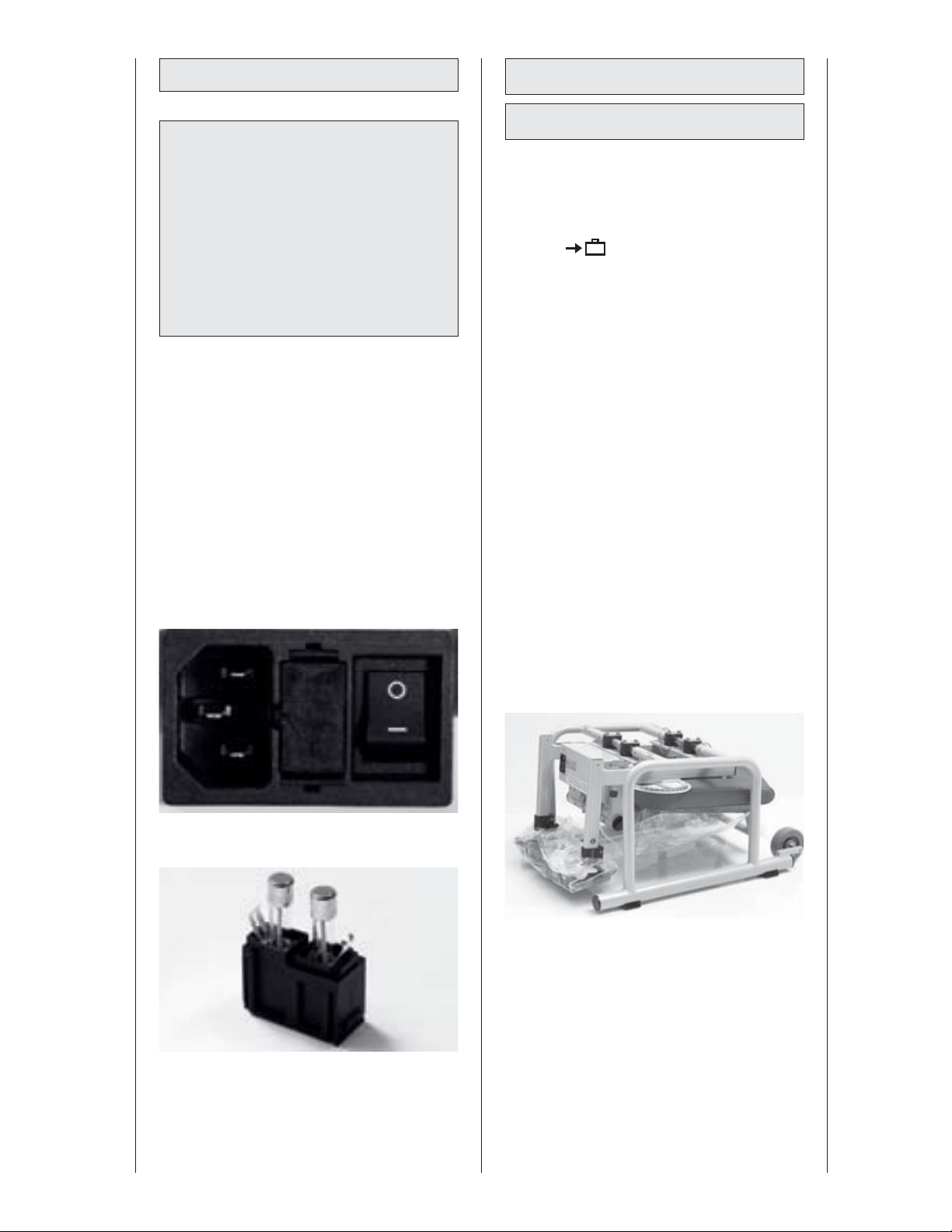
• Before replacing fuses turn o the
ARTROMOT®-E2/-E2 compact and
remove the power cord from the wall
outlet.
• Use an appropriate tool to remove the
fuse holder (20/8) situated between the
power switch (19) and the power connector (18) (Fig. 1).
• Replace the fuses and reinsert the fuse
holder (Fig. 2). Check that the fuse
holder locks properly into place.
6.3 Transport
6.3.1 ARTROMOT®-E2
The following operating steps must
be completed before transporting the
ARTROMOT®-E2:
1. Activate the “transport setting” function
and start the ARTROMOT®-E2.
2. Turn o the ARTROMOT®-E2 power
switch (19).
3. Remove the power cord (18) and disconnect the motion element (21) and
the programming unit (32).
4. Open locking screw (4) and pull out
the armrest (14) for the healthy arm.
5. Grasping the motion element at the
bracket (30) for adjustment of the positioning angle, open the locking screw
(4) and pull out the motion element.
6. Set horizontal adduction/abduction to
0° (indexing knob 1).
7. Open the locking screw for adjustment
of the backrest (10), fold the backrest
to the front all the way until at on the
seat and tighten the screw.
8. Remove the two locking pins (22). Pull
out the legs towards the sides, reverse
and reinsert. Then put the locking pins
back in place.
in the menu (see also 5.3)
Fig. 1
Fig. 2
9. Only use the original shipping box
for transporting the device. Ormed
GmbH & Co. KG cannot be held liable
for transport damage, if the device was
not shipped in its original shipping
box.
78
Page 33
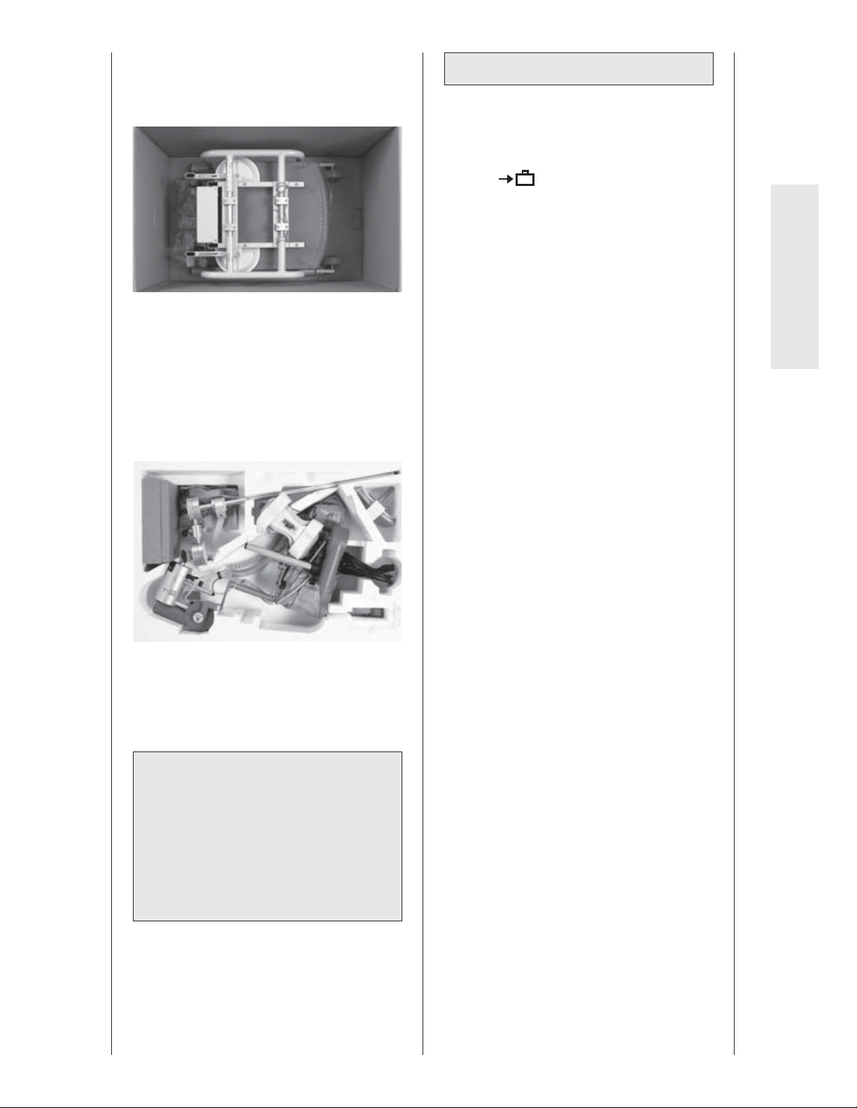
10. Place the ARTROMOT®-E2 - legs rst
- on the bottom of the bo
ings on the bottom of the box indicate
the correct position.
11. Then put the enclosed polystyrene
block on the chair, observing the cutouts in the block.
12. Put the programming unit (15) in
the supplied box. Place the motion
element, the armrest and the power
cord in the respective cut-outs in the
polystyrene block of the package.
13. Then close the box.
Reverse the above steps to reassemble
the device after transport.
x. The mark-
Warning!
Shock hazard—
Allow the ARTROMOT®-E2 to reach
room temperature before use. If the de-
vice has been transported at temperatures below 0 °C (32°F), leave it to dry
at room temperature for about 2 hours,
until any condensation has disappeared.
6.3.2 ARTROMOT®-E2 compact
The following operating steps must be
completed before transporting the
ARTROMOT®-E2 compact:
1. Activate the “transport setting” function
and start the ARTROMOT®-E2 compact.
2. Turn o the ARTROMOT®-E2 compact
power switch (19).
3. Remove the power cord (18) and
disconnect the motion element (9) and
the programming unit (16).
4. Remove pin (26) on the underside and
take o the upper arm support.
5. Remove pin (5) and take o the
swiveling mechanism of the upper arm
support. Set the guide of the upper
arm support to the transport setting
(parallel with motor A).
6. Grasping the motion element at the
bracket (27) for adjustment of the positioning angle, open the locking screw
(1) and pull out the motion element.
7. Open the locking screw for adjustment
of the elbow angle adjustment (2) and
separate the oval tube from the motion element.
8. Open locking screw (24) on the underside of the stand, then remove the
column with the electronics box from
the star-shaped stand.
9. Disassemble the stand by loosening
the ve legs with the special tool supplied and remove them.
10. Unscrew the locking screw (7) from
motor B (12), remove the entire
forearm support including the slider
(4) and the hand support (13 + 14).
Afterwards screw the locking screw (7)
back into motor B.
11. Only use the original shipping box
for transporting the device. Ormed
GmbH & Co. KG cannot be held liable
for transport damage, if the device was
not shipped in its original shipping
box.
12. Put the programming unit (15) in the
supplied box, using su cient padding.
in the menu (see also 5.3)
English
79
Page 34
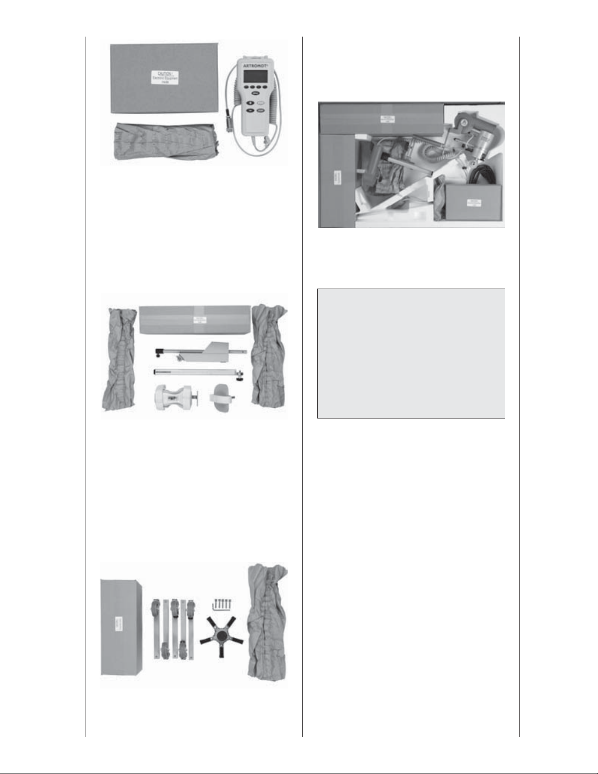
13. Pack the following items in the longer
box provided, again using su cient
padding:
• Upper arm support
• Oval tube of the motion element
• Column with electronics box
• Entire forearm support with slider and
hand support
15. Please put the motion element, the
power cord and the three smaller
boxes in the respective cut-outs of the
polystyrene block.
16. Then close the box.
Warning!
Shock hazard—
14. Pack the following items in the shorter
box provided, again using su cient
padding:
• Star-shaped stand
• 5 legs with castors
• 5 screws to attach the legs
• 5 washers to attach the legs
• 1 Allen key
Allow the ARTROMOT®-E2 compact to
reach room temperature before use.
If the device has been transported at
temperatures below 0 °C (32°F), leave
it to dry at room temperature for about
2 hours, until any condensation has
disappeared.
80
Page 35
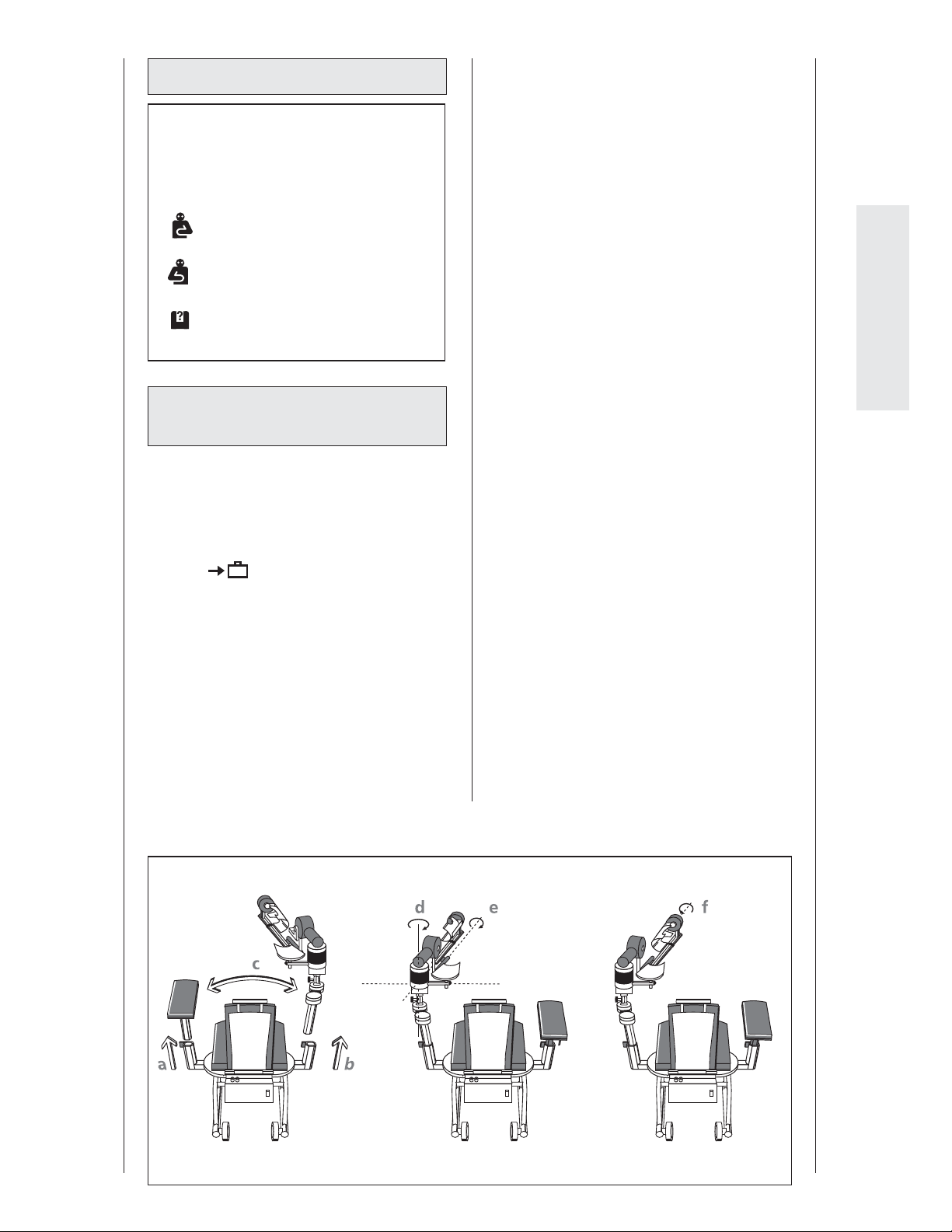
6.4 Conversion
Note!
On the display the respective sides are
indicated as follows:
-
The CPM device (upper arm sup-
port) is prepared for the left elbow.
The CPM device (upper arm sup-
port) is prepared for the right elbow.
This symbol appears during con-
version of the CPM device.
6.4.1 Recon guration of the
ARTROMOT®-E2
The ARTROMOT®-E2 can be used on the left
and on the right elbow joint. However, the
device must be converted rst. This is done
very quickly.
1. Activate the "transport setting" function
and start the ARTROMOT®-E2.
2. Adjust an angle of 90° for horizontal
adduction/abduction (indexing knob 1)
(see conversion drawing
3. Open locking screw (4) for the height
adjustment, remove the armrest for
the healthy arm and place it on the
seat (see conversion diagram
in the menu (see also 5.3)
1).
1).
4. Hold the double joint (3) of the motion
element and open the locking screw
for height adjustment (4) on this side
as well.
5. Remove the motion element and insert
it on the opposite side. Tighten the
locking screw (4).
(see conversion diagram
6. Pull the pin for the swiveling movement of the upper arm support (11)
downward and swing the support 180°
towards the inside.
Attention: Release the pin (11) while
the support is swinging; you will hear
it lock into place on the other side (see
conversion diagram
7. Open the locking screw for the swiveling movement of the forearm support
(12) and swing the support with motor
B 180°. Tighten locking screw (12) (see
conversion diagram
8. Open the locking screw for right/left
positioning (13) two revolutions. Move
the forearm support to the lower
recess in the slot and turn it 180° in
this position. Then move the forearm
support back to the middle position
(setting 0) and tighten locking screw
(13) again (see conversion diagram
1 b, c).
2 d)
2 e).
3 f).
English
Conversion diagram ARTROMOT®-E2:
123
81
Page 36
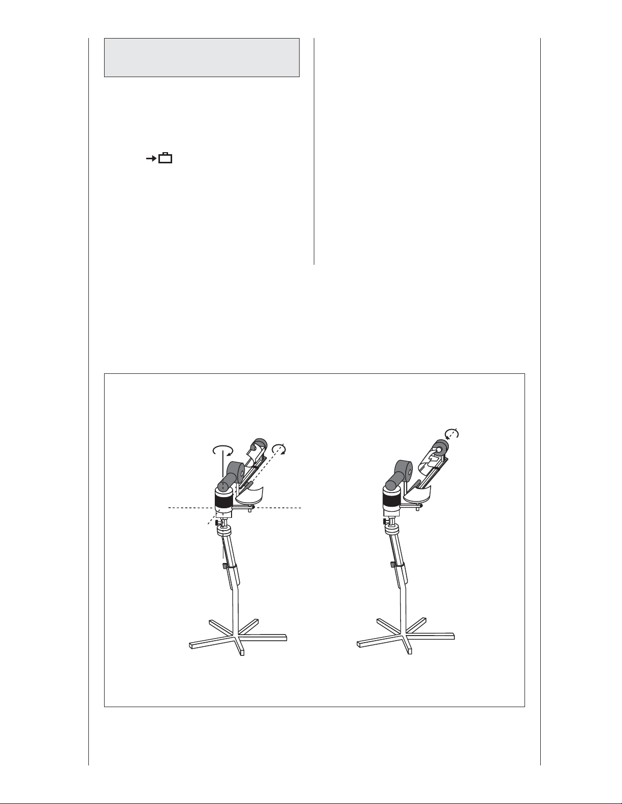
6.4.2 Recon guration of the
ARTROMOT®-E2 compact
The ARTROMOT®-E2 compact can be used
on the left and on the right elbow joint.
However, the device must be converted
rst. This is done very quickly.
1. Activate the "transport setting" function
and start the ARTROMOT®-E2 compact.
2. Release the wheel brakes (22) and roll
the ARTROMOT®-E2 compact to the
side of the elbow to be treated.
3. Pull the pin for the swiveling movement of the upper arm support (5)
downward and swing the support 180°
towards the inside.
in the menu (see also 5.3)
Attention: Release the pin (5) while the
support is swinging; you will hear it
lock into place on the other side (see
conversion diagram
4. Open the locking screw for the swiveling movement of the forearm support
(6) and swing the support with motor
B 180°.
Tighten locking screw (6) (see conver-
sion diagram
5. Open the locking screw for right/left
positioning (7) two revolutions. Move
the forearm support to the lower
recess in the slot and turn it 180° in
this position. Then move the forearm
support back to the middle position
(setting 0) and tighten locking screw
(7) again (see conversion diagram
1 a).
1 b).
2 c).
Conversion diagram ARTROMOT®-E2 compact:
ab
c
1
2
82
Page 37

7. Environmental Protection Statement
The product described in this operation
manual must not be disposed of with
unsorted household or municipal waste. It
requires separate disposal. Please contact
ORMED.DJO for information about the possible recycling of the product.
8. Speci cations
Input ratings: 100 – 240 V AC /
50 – 60 Hz
Rated current - motor: 2 A max.
Power consumption 33 VA
Fuses: 2 x T1A
Protection class: I
Applied part: type B
Dimensions (transport):
ARTROMOT®-E2
Length: 87.5 cm
Width: 57.5 cm
Height: 58 cm
ARTROMOT®-E2 compact
Length: 87.5 cm
Width: 57.5 cm
Height: 29 cm
Adjustment ranges (min./max.):
Height adjustment: 35 – 71 cm
(ARTROMOT®-E2 measured from the seat)
Forearm length: 29 – 46 cm
Seat height:
ARTROMOT®-E2 48 cm
Weight:
ARTROMOT®-E2
ARTROMOT®-E2 compact
Materials used: ABS, POM (Delrin
MDD: class 2a
Standards compliance: IEC 60601-1:1990
25 kg
17 kg
100), PUR, PA,
FR4, aluminum,
stainless steel,
brass
+ A1:1993
+ A2: 1995
No. 601.1-M90
UL 2601-1
EMC
(electromagnetic
compatibility)
Ambient conditions (storage, transport)
Ambient temperature: -24 ºC to +60ºC
Relative humidity: 20 % to 85 %
Atmospheric pressure: 700 hPa to
Ambient conditions (operation)
Ambient temperature: +10 ºC to +40ºC
Relative humidity: 30 % to 75 %
Atmospheric pressure: 700 hPa to 1060
____________________________________
Subject to change without notice (06/2008)
IEC 60601-12:2001
1060 hPa
hPa
English
83
Page 38
9. IEC 60601-1-2:2001
The ARTROMOT®-E2/-E2 compact is
subject to particular precautions regarding electromagnetic compatibility (EMC).
The device must be installed and put into
service strictly in compliance with the EMC
directives put forth in the accompanying
documents.
Portable and mobile RF communication
systems may a ect the
ARTROMOT®-E2/-E2 compact.
The ARTROMOT®-E2/-E2 compact should
not be used adjacent to or stacked with
other equipment. If adjacent or stacked use
is necessary, the
ARTROMOT®-E2/-E2 compact should be
observed to verify normal operation in the
con guration in which it will be used.
If you detect damage or malfunctions that
may impair the safety of the patient or
of the operator, have the device repaired
before using it.
If it is necessary to replace assemblies or
cables, only the manufacturer's original
parts must be used to ensure continued
compliance with EMC requirements after
repair. This requirement applies to the power supply unit, cables and cable lengths,
drive unit consisting of the motor and the
control system, the programming unit incl.
the coiled cable and the connector.
9.1 Electromagnetic emissions
Guidance and Manufacturer’s Declaration – Electromagnetic Emissions
The ARTROMOT®-E2/-E2 compact is intended for use in the electromagnetic environment speci ed
below. It is the responsibility of the customer or user to ensure that the ARTROMOT®-E2/-E2 compact is
used in such an environment.
Emissions test Compliance Electromagnetic environment - guidance
RF emissions
to CISPR 11
RF emissions
to CISPR 11
Harmonic emissions to IEC
61000-3-2
Voltage uctuations/ icker
emissions to IEC 61000-3-3
Group 1 The ARTROMOT®-E2/-E2 compact uses RF
energy only for its internal function. Therefore,
its RF emissions are very low and are not likely
to cause any interference in nearby electronic
equipment.
Class B The ARTROMOT®-E2/-E2 compact is suitable for
use in all establishments, including domestic
and those directly connected to the public lowvoltage power supply network that supplies
buildings used for domestic purposes.
not applicable
not applicable
84
84
Page 39
9.2 Electromagnetic immunity
Guidance and Manufacturer’s Declaration – Electromagnetic Immunity
The ARTROMOT®-E2/-E2 compact is intended for use in the electromagnetic environment speci ed
below. It is the responsibility of the customer or user to ensure that the ARTROMOT®-E2/-E2 compact is
used in such an environment.
Immunity test IEC 60601-
test level
Electrostatic discharge
(ESD) to IEC 61000-4-2
Electrical fast transient/
burst to IEC 61000-4-5
± 6 kV contact
± 8 kV air
± 2 kV for power
supply lines
± 1 kV for input/
output lines
Surges to IEC 61000-4-5 ± 1 kV di erential
mode
± 2 kV common
mode
) for
T
T
T
Voltage dips, short
interruptions and voltage variations on power
supply input lines to IEC
61000-4-11
< 5 % U
(> 95 % dip in
U
½ cycle
40 % U
(60 % dip in UT) for
5 cycles
70 % U
T
(30 % dip in UT) for
25 cycles
< 5 % U
T
(> 95 % dip in UT)
for 5s
Power frequency (50/60
3 A/m 3 A/m Power frequency magnetic elds
Hz) magnetic eld to
IEC 61000-4-8
NOTE: U
is the a.c. mains voltage prior to application of the test level.
T
Compliance level Electromagnetic environment
- guidance
± 6 kV contact
± 8 kV air
Floors should be wood, concrete
or ceramic tile. If oors are covered
with synthetic material, the relative
humidity should be at least
30%.
± 2 kV for power
supply lines
± 1 kV for input/
Mains power should be that of
a typical commercial or hospital
environment.
output lines
± 1 kV di erential
mode
± 2 kV common
Mains power should be that of
a typical commercial or hospital
environment.
mode
) for
T
T
Mains power should be that of
a typical commercial or hospital
environment. If the user of the
ARTROMOT®-E2/-E2 compact
requires continued operation dur-
T
ing power mains interruptions, it is
recommended that the
ARTROMOT®-E2/-E2 compact be
T
powered from an uninterruptible
power supply or a battery.
< 5 % U
(> 95 % dip in
U
½ cycle
40 % U
(60 % dip in UT) for
5 cycles
70 % U
(30 % dip in UT) for
25 cycles
< 5 % U
T
(> 95 % dip in UT)
for 5s
should be at levels characteristics of
a typical location in a typical commercial or hospital environment.
English
85
Page 40
9.2 Electromagnetic immunity
Guidance and Manufacturer’s Declaration – Electromagnetic Immunity
The ARTROMOT®-E2/-E2 compact is intended for use in the electromagnetic environment speci ed
below. It is the responsibility of the customer or user to ensure that the ARTROMOT®-E2/-E2 compact is
used in such an environment.
Immunity test IEC 60601 test
level
Conducted RF to IEC
61000-4-6
Radiated RF to IEC
61000-4-3
3 V
rms
150 kHz to 80MHz
3 V/m
80 MHz to 2.5GHz
Compliance level Electromagnetic environment
- guidance
Portable and mobile RF communications equipment are used no closer
to any part of the
ARTROMOT
®
-E2/-E2 compact, including cables, than the recommended
separation distance calculated
from the equation applicable to the
frequency of the transmitter.
Recommended separation distance:
3 V
rms
3 V/m
d = 1.2 öäP
d = 1.2
öäP
80 MHz to 800 MHz
d = 1.2
öäP
800 MHz to 2.5 GHz
where P is the maximum output
power rating of the transmitter in
watts (W) according to the transmitter manufacturer and d is the
recommended separation distance
in meters (m).
Field strengths from xed RF
transmitters, as determined by an
electromagnetic site survey
than the compliance level in each
frequency range
b
.
a
, is less
Interference may occur in the vicinity of equipment marked with the
following symbol
NOTE 1: At 80 MHz and 800 MHz, the higher frequency range applies.
NOTE 2: These guidelines may not apply in all situations. Electromagnetic propagation is a ected by
absorption and re ection from structures, objects, and people.
a) Field strengths from xed transmitters, such as base stations for radio (cellular/cordless) telephones
and land mobile radio, AM and FM radio broadcast and TV broadcast cannot be predicted theoretically with accuracy. To assess the electromagnetic environment due to xed RF transmitters, an
electromagnetic site survey should be considered. If the measured eld strength in the location in
which the ARTROMOT®-E2/-E2 compact is used exceeds the applicable RF compliance level above,
the ARTROMOT®-E2/-E2 compact device should be observed to verify normal operation. If abnormal
performance is observed, additional measures may be necessary, such as reorienting or relocating the
ARTROMOT®-E2/-E2 compact.
b) Over the frequency range 150 kHz to 80 MHz, eld strengths should be less than 3 V/m.
86
Page 41
9.3 Recommended separation distances
Recommended separation distances between portable and mobile RF communications equipment
and the ARTROMOT®-E2/-E2 compact
The ARTROMOT®-E2/-E2 compact is intended for use in an electromagnetic environment in which radiated RF disturbances are controlled. The customer or the user of the ARTROMOT®-E2/-E2 compact can
help prevent electromagnetic interferences by maintaining a minimum distance between portable and
mobile RF communications equipment (transmitters) and the ARTROMOT®-E2/-E2 compact as recommended below, according to the maximum output power of the communications equipment.
rated maximum output
power of transmitter
W
0.01 0.12 0.12 0.23
0.1 0.38 0.38 0.73
1 1.2 1.2 2.3
10 3.8 3.8 7.3
100 12 12 23
For transmitters rated at a maximum output power not listed above, the recommended separation distance d in meters (m) can be estimated using the equation applicable to the frequency of the transmitter,
where P is the maximum output power rating of the transmitter in watts (W) according to the transmitter
manufacturer.
separation distance according to frequency of transmitter
m
150 kHz to 80 MHz
d = 1.2
öäP
80 MHz to 800 MHz
d = 1.2 öäP
800 MHz to 2.5 GHz
d = 1.2 öäP
English
NOTE 1: For calculation of the recommended separation distance of transmitters in the frequency range
from 80 MHz to 2.5 GHz an additional factor of 10/3 was taken into account to reduce the probability of
mobile/portable communications equipment brought into the patient environment by accident causing
any malfunction.
NOTE 2: These guidelines may not apply in all situations. Electromagnetic propagation is a ected by
absorption and re ection from structures, objects, and people.
10. Contact
We would be happy to answer any questions you may have about our products
and services.
■ ORMED.DJO international
Please contact your local dealer or the
ORMED.DJO headquarters in Germany.
■ Headquarters Germany
ORMED.DJO
ORMED GmbH & Co. KG
Merzhauser Strasse 112
D-79100 Freiburg - Germany
Tel. +49 761 45 66-01
Fax +49 761 45 66 55-01
Warranty:
2 years (mechanical parts)
2 years (electronics)
Sales:
ORMED.DJO
ORMED GmbH & Co. KG
Merzhauser Strasse 112
D-79100 Freiburg - Germany
■ Internet
www.ormed-djo.de
e-mail: [email protected]
87
Page 42
11. Technical service
11.1 Technical hotline
Do you have any technical questions?
Do you need technical service?
Phone: +49-180-5-1 ormed de
+49-180-5-1 67 63 33
Fax: +49-180-5-3 ormed de
+49-180-5-3 67 63 33
11.2 Shipment
To prevent damage during transport, only
use the original shipping box. These boxes
can be obtained from ORMED.DJO.
Before packing the CPM device, set it to the
transport position (see chapters 5 and 6).
Surcharges may apply in certain cases to
spare parts ordered in low quantities.
Item Description Part no. Qty
1. Patient chip card 0.0034.048
2. Patient chip card
(protocol)
3. Marker pen for
patient chip card
0.0037.035
0.0031.006
11.3 Spare parts
Refer to the Service Manual for the most
recent list of spare parts.
When ordering spare parts, always specify:
- Item
- Description
- Part no.
- Quantity
- Serial number of the CPM device
Note!
Refer repairs to authorized, specially
trained sta .
ORMED GmbH & Co. KG o ers service
training for your personnel.
88
Page 43

Declaration of conformity
In compliance with the Council Directive 93/42/EEC of
14 June 1993 concerning medical devices, the company
ORMED GmbH & Co.KG
Merzhauser Strasse 112
D-79100 Freiburg - Germany
declares that the products of the product line
ARTROMOT
ful ll the requirements of the Council Directive 93/42/EEC of 14 June 1993, Annex II
as well as the essential requirements of Annex I.
With reference to Rule 9 of the Directive 93/42/EEC, these products are devices of risk
class IIa.
0297
Freiburg, 28 July 2008
_____________________________________
- QA Management Representative -
®
(see Annex)
English
DECLARATION OF CONFORMITY
This certi cate is valid through: 28 July 2010
Annex:
ARTROMOT®-S2 PRO
ARTROMOT®-S3
ARTROMOT®-S3 Comfort
ARTROMOT®-K1
ARTROMOT®-K2
ARTROMOT®-K2 PRO
ARTROMOT®-K2 PRO Chip
ARTROMOT®-K3
ARTROMOT®-K4
ARTROMOT®-SP2
ARTROMOT®-SP3
ARTROMOT®-E2
ARTROMOT®-E2 compact
89
Page 44
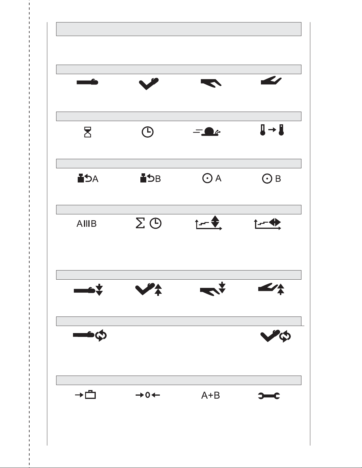
Piktogrammübersicht ARTROMOT®-E2/-E2 compact
Symbol Overview ARTROMOT®-E2/-E2 compact
EBENE 1/LEVEL 1:
Extension Flexion Pronation Supination
EBENE 2/LEVEL 2:
Pause Timer Geschwindigkeit Aufwärmprogramm
speed warm up protocol
EBENE 3/LEVEL 3:
Lastumkehr Motor A Lastumkehr Motor B Motor A Ein/Aus Motor B Ein/Aus
load reversal motor A load reversal motor B motor A ON/OFF motor B ON/OFF
EBENE 4/LEVEL 4:
Isolationsprogramm
isolation protocol
Gesamttherapiezeit
total therapy time
Therapieverlaufs-
dokumentation
Extension/Flexion
abduction/adduction
therapy documentation
Behandelverloop-
documentatie
pronatie/supinatie
pronation/supination
therapy documentation
EBENE 5/LEVEL 5:
Dehnung Extension Dehnung Flexion Dehnung Pronation Dehnung Supination
stretching in extension stretching in exion stretching in pronation stretching in supination
EBENE 6/LEVEL 6:
Endgradige
Wiederholung
EROM repeat
Extension/Pronation
Endgradige
Wiederholung
EROM repeat
Flexion/Supination
EBENE 7/LEVEL 7:
Transporteinstellung
transport setting
Neuer Patient
new patient
Betriebsart
Synchron/Asynchron
synchronized/non-syn-
chronized mode
Service-Menü
service menu
✃
265
Page 45

266
Page 46
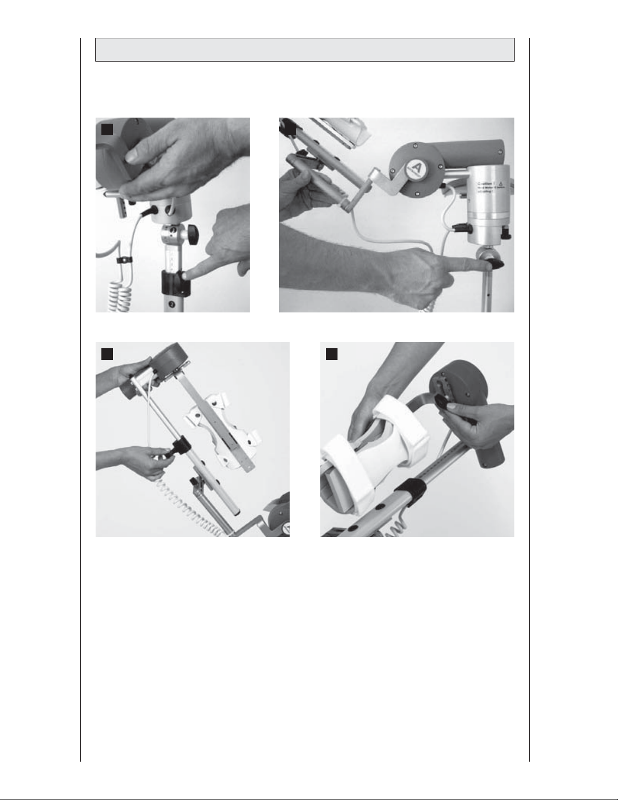
Abbildungen ARTROMOT®-E2 compact
Figures
Illustrations
A B
C D
Ilustraciones
Illustrazioni
267
Page 47
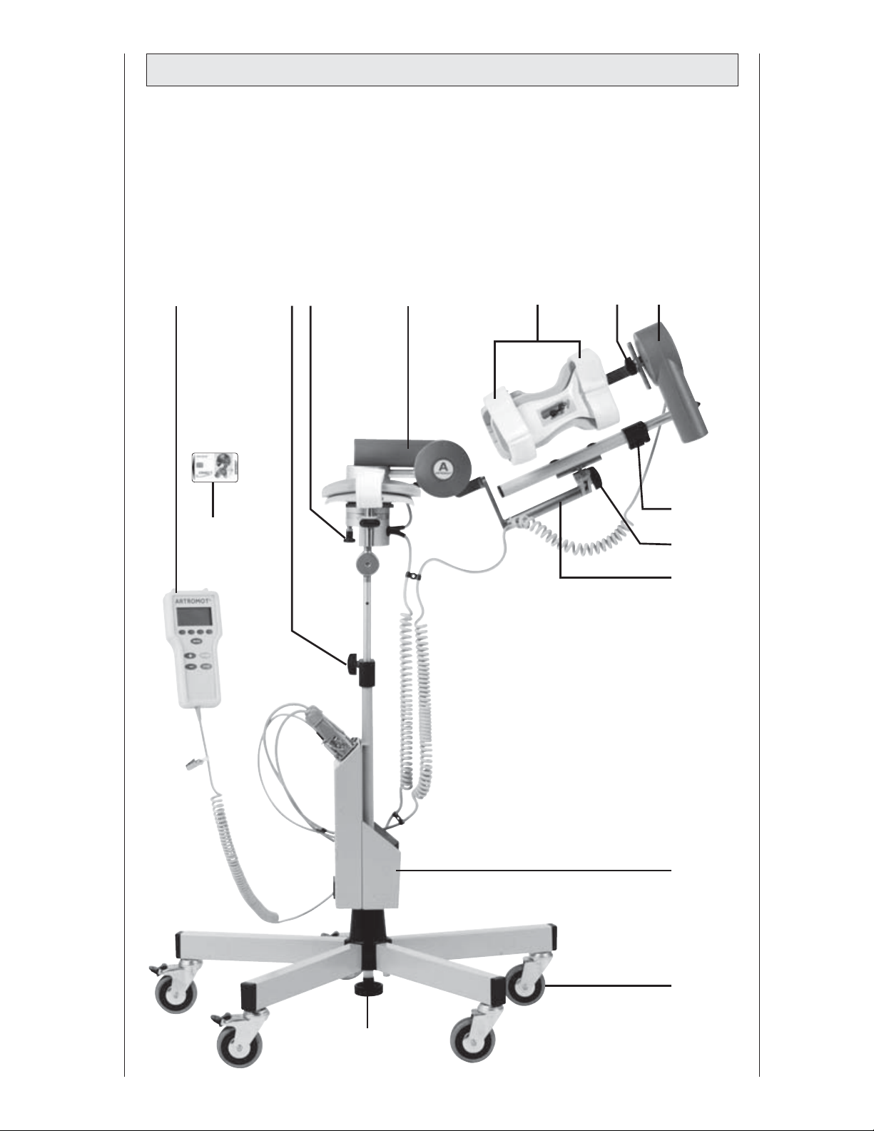
Gerätebeschreibung ARTROMOT®-E2 compact
Device description
Description de l'appareil
Descripción del aparato
Descrizione dell'apparecchiatura
Beschrijving van het apparaat
15 11
17
1
5
10
712
3
6
27
24
23
25
268
Page 48
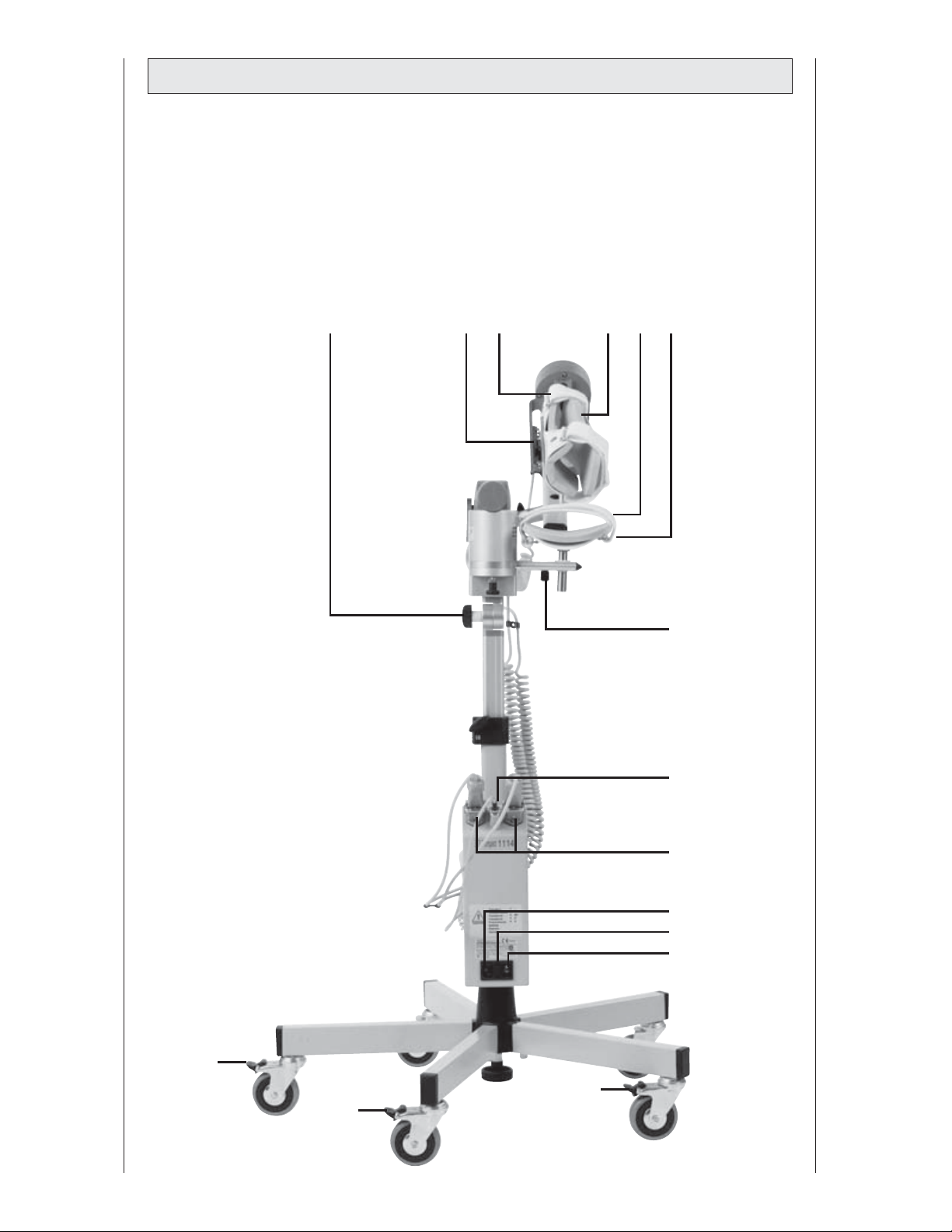
Gerätebeschreibung ARTROMOT®-E2 compact
Device description
Description de l'appareil
Descripción del aparato
Descrizione dell'apparecchiatura
Beschrijving van het apparaat
2 4 14 13 21 20
22
26
16
9
18
8
19
22
22
269
Page 49
DIN EN 13485 ORMED Nr. 018 829-01
ORMED.DJO-MOT-324-01/01-8/08
ORMED GmbH & Co. KG
Merzhauser Str. 112 • D-79100 Freiburg, Germany
Tel. 0180 1 676 333, Fax 0180 11 676 333 • E-mail: [email protected]
Technical Hotline: +49 180 51 676 333, Fax +49 180 53 676 333
www.ormed-djo.de
 Loading...