

Ormazabal PF201, PF301, PF202, PF 302, PF203 General Instructions Manual
...
IG-021-GB
version 07
General Instructions
MODULAR ENCLOSURES FOR
TRANSFORMER SUBSTATIONS
PF
LIB
29.08.2008
Transformer
Substations
Secondary Distribution
Switchgear
Primary Distribution
Switchgear
Protection and
Automation
Low Voltage
Boards
Distribution
Transformers

Legal Deposit: BI-2359/08
ATTENTION!
When MV equipment is operating, certain components are live, other parts may be in movement, and some may reach high
temperatures. Therefore, the use of this equipment poses electrical, mechanical and thermal risks.
In order to ensure an acceptable level of protection for people and property, and in compliance with applicable environmental
recommendations, Ormazabal designs and manufactures its products according to the principle of integrated safety, based on
the following criteria:
• Elimination of hazards wherever possible.
• Where elimination of hazards is not technically or economically feasible, appropriate protection functions are
incorporated in the equipment.
• Provision of information on residual risks to facilitate the design of operating procedures which prevent such
risks, training for the personnel in charge of the equipment, and the use of suitable measures for personal
protection.
• Use of recyclable materials and establishment of procedures for the disposal of equipment and components so
that once the end of their useful lives is reached, they are duly processed in accordance, as far as possible, with
the environmental restrictions established by the competent authorities.
Consequently, the equipment to which the present manual refers complies with the requirements of section 11.2 of the
forthcoming IEC standard 62271-1. It must only be operated by qualified and supervised personnel, in accordance with the
requirements of standard EN 50110-1 on the safety of electrical installations and standard EN 50110-2 on activities in or near
electrical installations. Personnel must be fully familiar with the instructions and warnings contained in this manual and in other
recommendations of a more general nature which are applicable to the situation according to current legislation.
The above must be carefully observed, as the correct and safe operation of this equipment depends not only on its design but
also on general circumstances which are in general beyond the control and responsibility of the manufacturer. More specifically:
• The equipment must be handled and transported appropriately from the factory to the place of installation.
• All intermediate storage should occur in conditions which do not alter or damage the characteristics of the
equipment or its essential components.
• Service conditions must be compatible with the equipment rating.
• The equipment must be operated strictly in accordance with the instructions given in the manual, and the
applicable operating and safety principles must be clearly understood.
• Maintenance should be performed properly, taking into account the actual service and environmental conditions
in the place of installation.
The manufacturer declines all liability for any significant indirect damages resulting from violation of the guarantee, under any
jurisdiction, including loss of income, stoppages and costs resulting from repair or replacement of parts.
Guarantee
The manufacturer guarantees this product against any defect in materials and operation during the contractual period. In the
event that defects are detected, the manufacturer may opt either to repair or replace the equipment. Improper handling of this
equipment and its repair by the user shall constitute a violation of the guarantee.
Registered Trademarks and Copyrights
All registered trademarks cited in this document are the property of their respective owners. The intellectual property of this
manual belongs to the manufacturer.
In view of the constant evolution in standards and design, the characteristics of the elements contained in this manual are
subject to change without prior notification.
These characteristics, as well as the availability of components, are subject to confirmation by Ormazabal’s Technical - Commercial
Department.

IG-021-GB
version 07
29.08.2008
GENERAL INSTRUCTIONS FOR PF
MODULAR ENCLOSURES FOR
TRANSFORMER SUBSTATIONS
CONTENTS
1. DESCRIPTION AND MAIN CHARACTERISTICS ........................................................ 4
2. TRANSPORT................................................................................................................. 5
2.1. ACCESS ...................................................................................................................... 5
2.2. TRANSPORT............................................................................................................... 5
3. INSTALLATION............................................................................................................. 8
3.1. LOCATION .................................................................................................................. 8
3.2. PLANNING .................................................................................................................. 8
3.3. PREPARING THE GROUND....................................................................................... 9
3.3.1. Excavation Dimensions........................................................................................ 9
3.3.2. Types of Ground .................................................................................................. 9
3.4. LEVELLING PROCESS ............................................................................................ 10
3.4.1. Levelling Tools ................................................................................................... 10
3.5. HANDLING PANELS AND CONCRETE COMPONENTS........................................ 13
3.5.1. PF-200 / 300 & PF-2015 / 3015 SERIES CONCRETE COMPONENTS ........... 14
3.6. ASSEMBLING TOOLS.............................................................................................. 15
3.7. PF ENCLOSURE ASSEMBLY PROCESS ............................................................... 15
3.7.1. Assembling Bottom Plates ................................................................................. 17
3.7.2. Assembling the Vertical Panels.......................................................................... 20
3.7.3. Remaining Vertical Panels................................................................................. 26
3.7.4. Floor Plates, Slabs and Transformer Platform ................................................... 30
3.7.5. Cubicles and Transformer.................................................................................. 34
3.7.6. Low Voltage Board............................................................................................. 34
3.7.7. Transformer Protection Fences.......................................................................... 35
3.7.8. Covers................................................................................................................ 35
3.7.9. Ventilation grilles................................................................................................ 37
3.7.10. Doors.................................................................................................................. 38
3.7.11. Low Voltage Auxiliary Feeder ............................................................................ 39
3.8. CONNECTING THE EARTH CIRCUIT...................................................................... 40
3.8.1. Panel Reinforcing Mesh..................................................................................... 40
3.8.2. Earthing Circuit................................................................................................... 42
3.8.3. Earthing Ring ..................................................................................................... 43
4. MAINTENANCE .......................................................................................................... 44
4.1. REMOVING THE SIDE COVERS.............................................................................. 44
4.2. REMOVING THE CENTRAL COVERS ..................................................................... 44
4848
Page 3 of 48

GENERAL INSTRUCTIONS FOR PF
MODULAR ENCLOSURES FOR
TRANSFORMER SUBSTATIONS
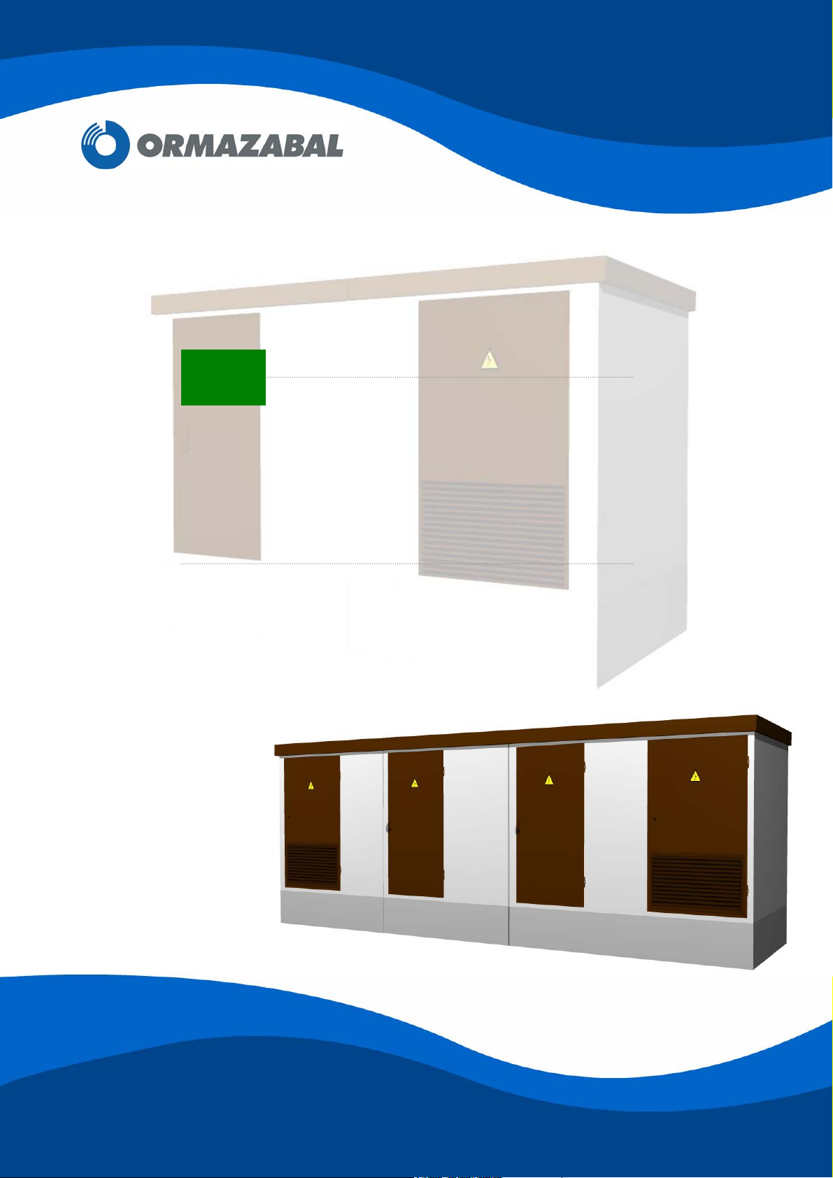
1. DESCRIPTION AND MAIN CHARACTERISTICS
Ormazabal’s PF Modular Enclosures for walk-in type outdoor Transformer Substations are
designed according to standard EN 61330 for use in electrical power distribution networks up
to 36 kV.
PF consists of prefabricated concrete panels that can be combined in various configurations.
Depending on their configuration, these enclosures comprise some of the following elements:
Front, back and side concrete modular panels.
Covers (roof panels).
Transformer platforms.
Bottom plates.
IG-021-GB
version 07
29.08.2008
Supplementary floor plates.
Hinged personnel access door, folding 180º over the outside wall, with a two-fixing-
point lock and a fastening rod to hold it open.
Hinged transformer door, folding 180º over the outside wall, and with a ventilation
grille in its lower section. An interlocking lock may be fitted.
Ventilation grilles: for transformer powers under or equal to 630 kVA, an air exhaust
grille is fitted in the rear upper part of the enclosure and an air intake grille is fitted in
the lower part of the transformer door. For transformer powers of 1000 kVA, 4 extra
grilles are incorporated in the sides.
Moulded holes for LV and MV cable input/output. Some of these holes can be used
for the output of the earthing circuit cables.
Oil collection pit with a fire-extinguisher device.
Document holder for documentation relating to the Transformer Substation.
Page 4 of 48
IG-021-GB
version 07
29.08.2008
GENERAL INSTRUCTIONS FOR PF
MODULAR ENCLOSURES FOR
TRANSFORMER SUBSTATIONS
2. TRANSPORT
2.1. ACCESS
The site must be visited in advance to check if vehicles (tow-truck or separate truck and
crane) can have access and if there is sufficient space for the PF unloading and assembly
operations, taking into account the distances to overhead lines, slopes, etc.
2.2. TRANSPORT
The panels are transported in trucks, taking the appropriate precautions to avoid breakage
caused by differential settlements.
The elements required to assemble the PF Transformer Substation are grouped into two
classes, according to how they are transported:
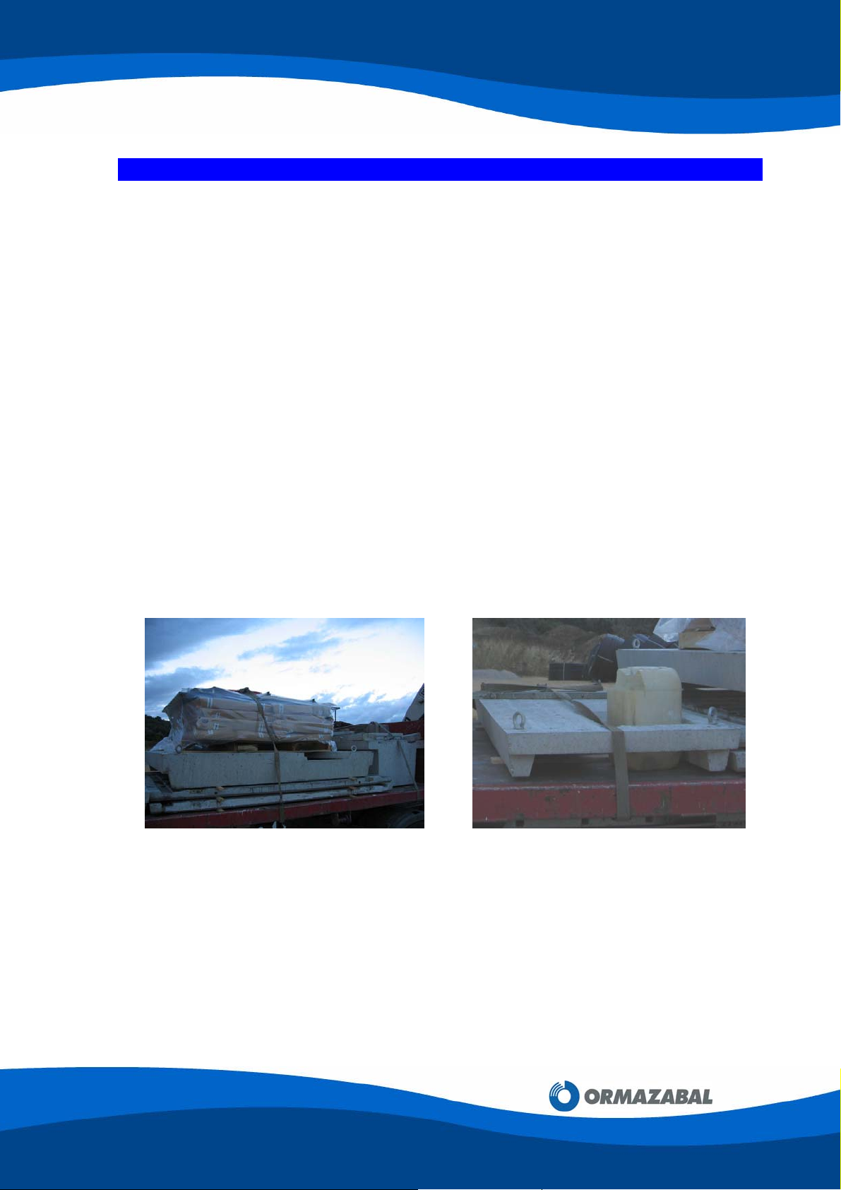
a) Horizontally-transported components
Transformer platforms, PF-200/300 series bottom plates and supplementary floor plates
are transported lying flat on the truck bed, separating them with wooden battens to avoid
damage to the edges.
Apart from these components, other miscellaneous material such as floor slabs, grilles,
doors, etc., are transported on wooden pallets on the truck bed.
They are tied down using slings suitable for the load.
Figure 2.1: Fixing slings
Figure 2.2: Fixing slings
4848
Page 5 of 48
GENERAL INSTRUCTIONS FOR PF
MODULAR ENCLOSURES FOR
TRANSFORMER SUBSTATIONS
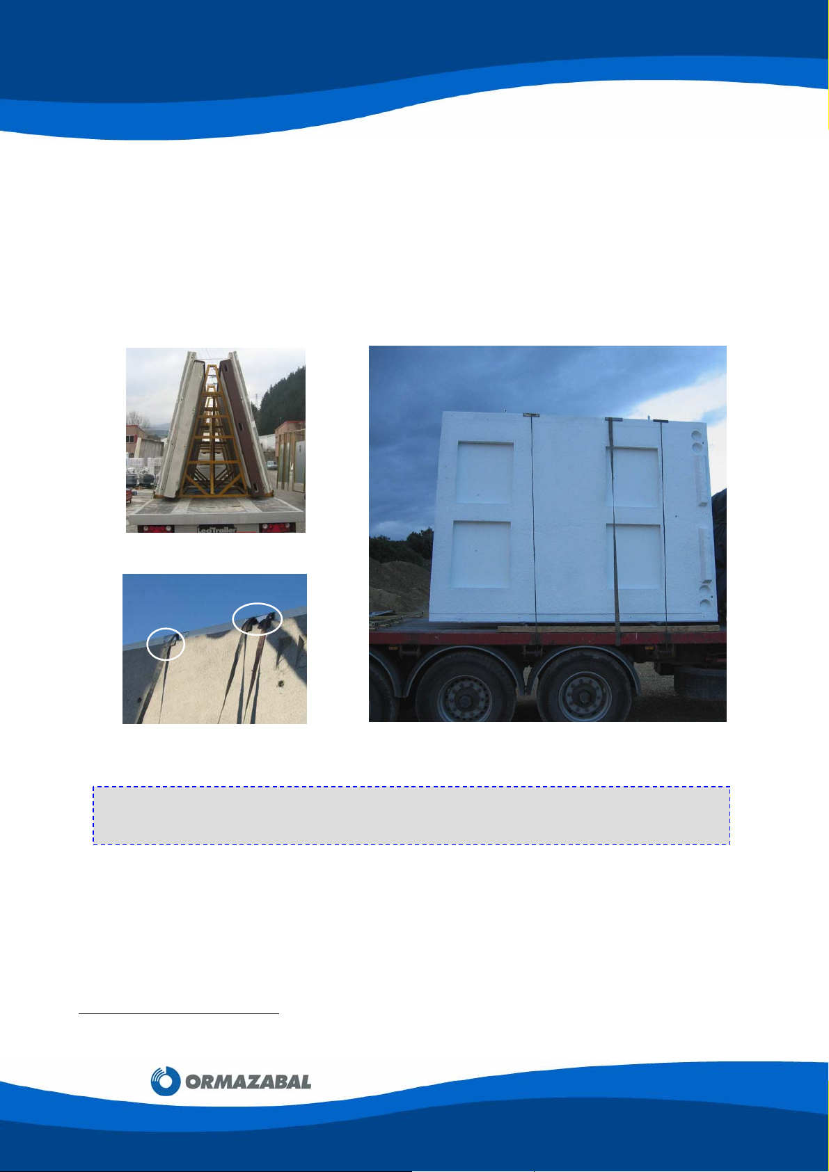
b) Vertically-transported components
Front and side panels
[1]
, PF-2015 / 3015 series bottom plates and the remaining floor
plates are transported on trestle (reference 160026), as shown in figure 2.3. On
occasions, floor plates can be transported horizontally.
The load is tied down on the truck using slings or cables that are tensed using the truck’s
reels. In turn, the concrete components have rubber and/or metal protection parts, as
shown in figure 2.4, to avoid any damage as the straps are tightened.
Figure 2.3: Trestle160026
Figure 2.4: Protection parts Figure 2.5: Vertically-transported components
IMPORTANT:
Before unloading, check the orientation of the loaded components. This will make unloading
and assembly easier.
IG-021-GB
version 07
29.08.2008
[1]
If the front and rear panels are transported vertically, instead of horizontally, they can be moved directly from
the truck to their final positions.
Page 6 of 48
IG-021-GB
version 07
29.08.2008
GENERAL INSTRUCTIONS FOR PF
MODULAR ENCLOSURES FOR
TRANSFORMER SUBSTATIONS
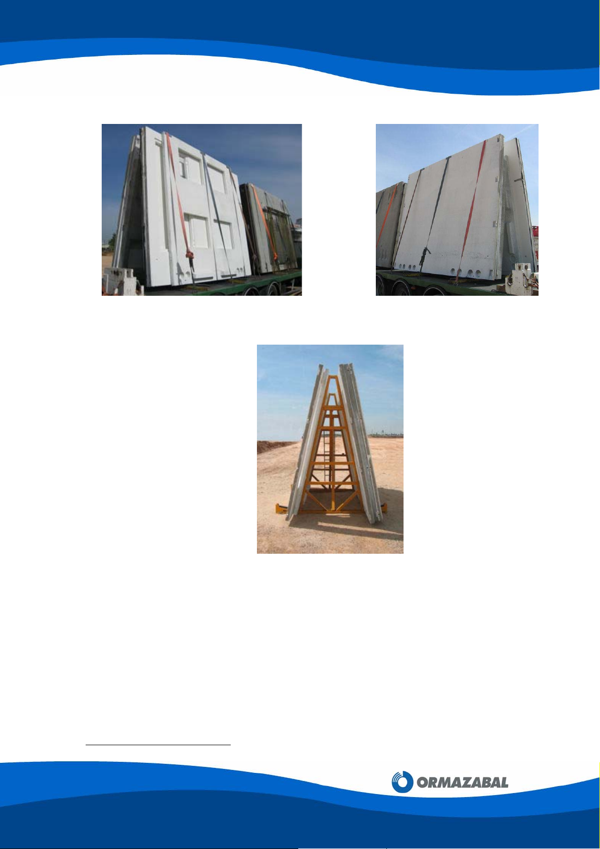
Figure 2.6: 2360 mm wide panel placed vertically
Figure 2.7: 3540 mm wide panel placed vertically
Figure 2.8: Panels supported by a trestle
Side panels must be rested on the ground in order to insert the rubber strip required for
sealing the enclosures
[2]
.
[2]
See section 3.7. PF Enclosure Assembly Process.
4848
Page 7 of 48

GENERAL INSTRUCTIONS FOR PF
MODULAR ENCLOSURES FOR
TRANSFORMER SUBSTATIONS
Preferably, the truck used to transport the components should have a bed height no more
than 900 mm; there are two possible cases:
200/2015 Series panels
The maximum height of these panels when transported vertically is 3000 mm, enabling
them to be transported on low loaders up to 900 mm high without requiring a special
permit.
When this is not possible, a special transport permit should be obtained. In this case, the
truck bed height should be no more than 1400 mm, in order not to exceed the maximum
permitted height of 4500 mm.
300/3015 Series panels
[3]
The maximum height of these panels when transported vertically is 3,400 mm, as a result
of which they exceed 4000 mm in height both when carried on 900 mm high low loaders
and in other types of truck. Therefore, a special permit is required to transport them, and
the maximum permitted height of 4500 mm must never be exceeded.
3. INSTALLATION
IG-021-GB
version 07
29.08.2008
Assembly and installation of PF TS must only be carried out by qualified personnel with
sufficient experience and training. All safety rules for unloading and handling elevated loads
must be observed. Operators must use the obligatory personal protection equipment,
helmets and protective footwear.
3.1. LOCATION
The site location should be defined exactly, indicating the levels of alignment and height to
reference points, such as: roads, kerbs, milestones, pavilions, fences, electricity pylons, etc.
It is recommended, although it is not essential, to get a drawing or sketch with the customer’s
letter head and stamp and/or signature, indicating these distances.
3.2. PLANNING
On the location sketch or drawing (or on another one), mark out the spaces available for the
crane and the transport truck.
In addition, indicate the existence of any circumstance or object that could impede or
obstruct the smooth operation of the installation (posts, cables, ditches, walls, pipelines,
etc.), marking their positions on the drawing with the corresponding measurements.
[3]
The maximum height limit for vehicles, including the load, is specified in the Spanish Royal Decree 2822/1998
dated the 23rd December, which approved the General Vehicle Regulations (Article 14, Annex IX).
Page 8 of 48
IG-021-GB
version 07
29.08.2008
GENERAL INSTRUCTIONS FOR PF
MODULAR ENCLOSURES FOR
TRANSFORMER SUBSTATIONS
Confirm that the crane is sufficiently powerful to unload the components comprising the
transformer substation (the maximum weight of any individual part is about 2500 kg) and that
it can move them the distances required to install the transformer substation.
3.3. PREPARING THE GROUND
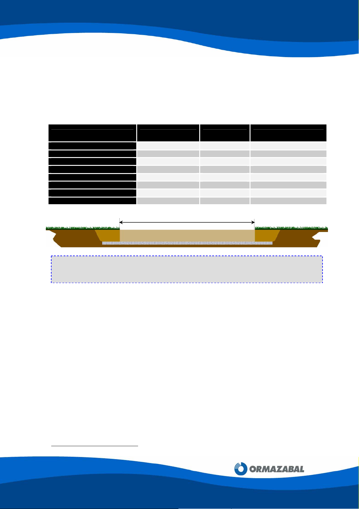
3.3.1. Excavation Dimensions
The excavation dimensions depend on the enclosure model:
MODEL LENGTH (L) [mm] WIDTH [mm] DEPTH [mm]
PF201 / PF301
PF202 / PF302
PF203 / PF303
PF204 / PF304
PF205 / PF305
PF2015 / PF3015
PF2030 / PF3030
PF3035
3420 3420 650
5680 3420 650
8040 3420 650
10400 3420 650
12760 3420 650
4500 3420 650
8040 3420 650
9220 3420 650
L
NOTE: For other configurations, the distance L must be increased by 2360 mm for each
additional 200/300 series panel, and by 3540 mm for each additional 2015/3015 series
panel. Consult Ormazabal’s Technical - Commercial Department.
3.3.2. Types of Ground
The type of ground on which the PF Modular Transformer Substation will rest is an essential
factor, given the weight of the equipment. The ground could subside or become uneven, or
could provide differential settlements, causing cracks in the enclosure.
There are two types of ground:
A) Hard Grounds: Grounds where the soil is settled and properly compacted by natural
causes, with a strength of at least 1 kg/cm
2
.
When the excavation is finished, a sand layer of approximately 100 mm should be laid
down and compacted until a person can walk on it without leaving footprints (only a
surface mark).
Once the levelling boards
[4]
have been removed, the gaps they leave should be filled with
sand. Take the measures appropriate to each case to prevent the filling sand from
eroding.
[4]
See section 3.4. Levelling process
4848
Page 9 of 48
IG-021-GB
GENERAL INSTRUCTIONS FOR PF
MODULAR ENCLOSURES FOR
TRANSFORMER SUBSTATIONS
29.08.2008
B) Soft Grounds: These are sandy areas, landfills, etc., with a strength of less than
0.9 – 1 kg/cm
2
.
In these cases, foundations suitable for the ground conditions must be prepared, and this
may imply the construction of a reinforced concrete bed to distribute the load over a wider
surface
[5]
.
Thereafter, it should be levelled using sand, as in the previous case.
3.4. LEVELLING PROCESS
This is a fundamental operation which has a decisive influence in both the assembly and the
stability of the PF Modular Transformer Substation.
3.4.1. Levelling Tools
1 Spirit Level
1 Pickaxe
1 Round-end spade
1 Square-end spade
1 Wooden or Plastic lump hammer
1 Levelling board set (reference 3947251-10)
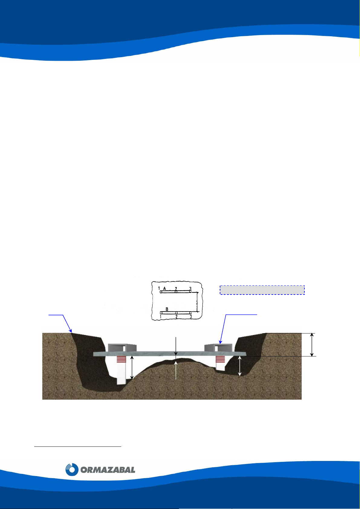
A) Normal Conditions
The levelling boards are placed according to the measurements on the drawing below
(the level of 3100 mm is a minimum value).
0 Level
A B
150
Figure 3.1: Levelling Specifications
Once the levelling rods have been positioned, the levelling boards should be used to check
that the ground is in perfect condition.
3100
20
Dimensions in millimeters
Levelling board
550
80
version 07
[5]
Consult Ormazabal’s Technical-Commercial Department.
Page 10 of 48
IG-021-GB
version 07
29.08.2008
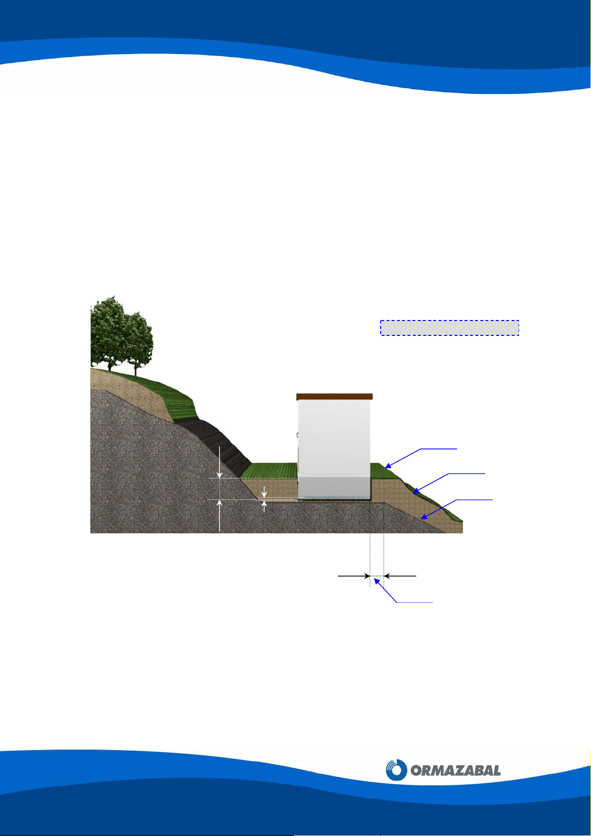
B) Sloping Grounds
The excavation should be prepared in such a way that the base platform is on a hard
area.
In these cases, it is essential that rainwater from the higher ground be channelled, to
avoid it washing the ground away from under the enclosure.
If there are any doubts concerning this subsequent channelling, it is best to use a
mixture of sand and cement when levelling the ground.
Example:
650
GENERAL INSTRUCTIONS FOR PF
MODULAR ENCLOSURES FOR
TRANSFORMER SUBSTATIONS
Dimensions in millimeters
0 Level
Landfill or vegetal matter
Hard ground
100
100
Minimum level
4848
Figure 3.2: Sloping Grounds
Page 11 of 48

GENERAL INSTRUCTIONS FOR PF
MODULAR ENCLOSURES FOR
TRANSFORMER SUBSTATIONS
C) Ground with a High Water Table
When there is a high water table, proceed as follows:
1) Establish the water table level.
2) Excavate no deeper than necessary, then level the ground as in sections A) and
B), above.
Example:
Water table
Figure 3.3: Ground with a High Water Table
IG-021-GB
version 07
29.08.2008
Dimensions in millimeters
0 Level
350
550
100
Page 12 of 48
IG-021-GB
version 07
29.08.2008
GENERAL INSTRUCTIONS FOR PF
MODULAR ENCLOSURES FOR
TRANSFORMER SUBSTATIONS
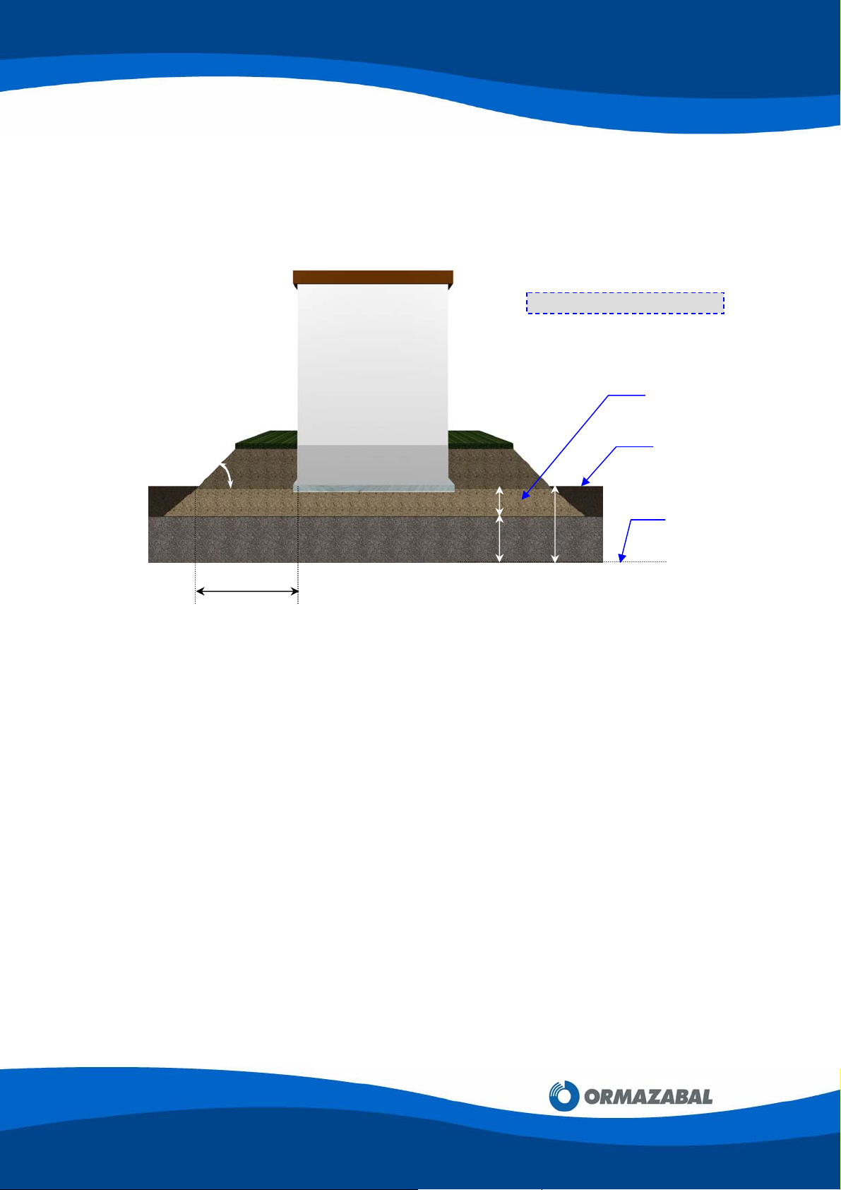
D) Grounds at Risk of Flooding
In these cases, the enclosure bottom plate should be raised to 100 mm above the
predicted flood level, and then level the foundations as in section A).
Example:
Dimensions in millimeters
45º
100 200
300
X
Figure 3.4: Grounds at Risk of Flooding
The landfill should be such that the distance X is at least 400 mm and the slope angle
is 45°.
A one-meter wide pavement around the enclosure is recommended.
Since these cases are found near rivers, the landfill must be firmly retained (with
concrete, rockfill, etc) to provide stability to the prefabricated enclosure.
3.5. HANDLING PANELS AND CONCRETE COMPONENTS
Predicted Flood Level
Landfill height
0 Level
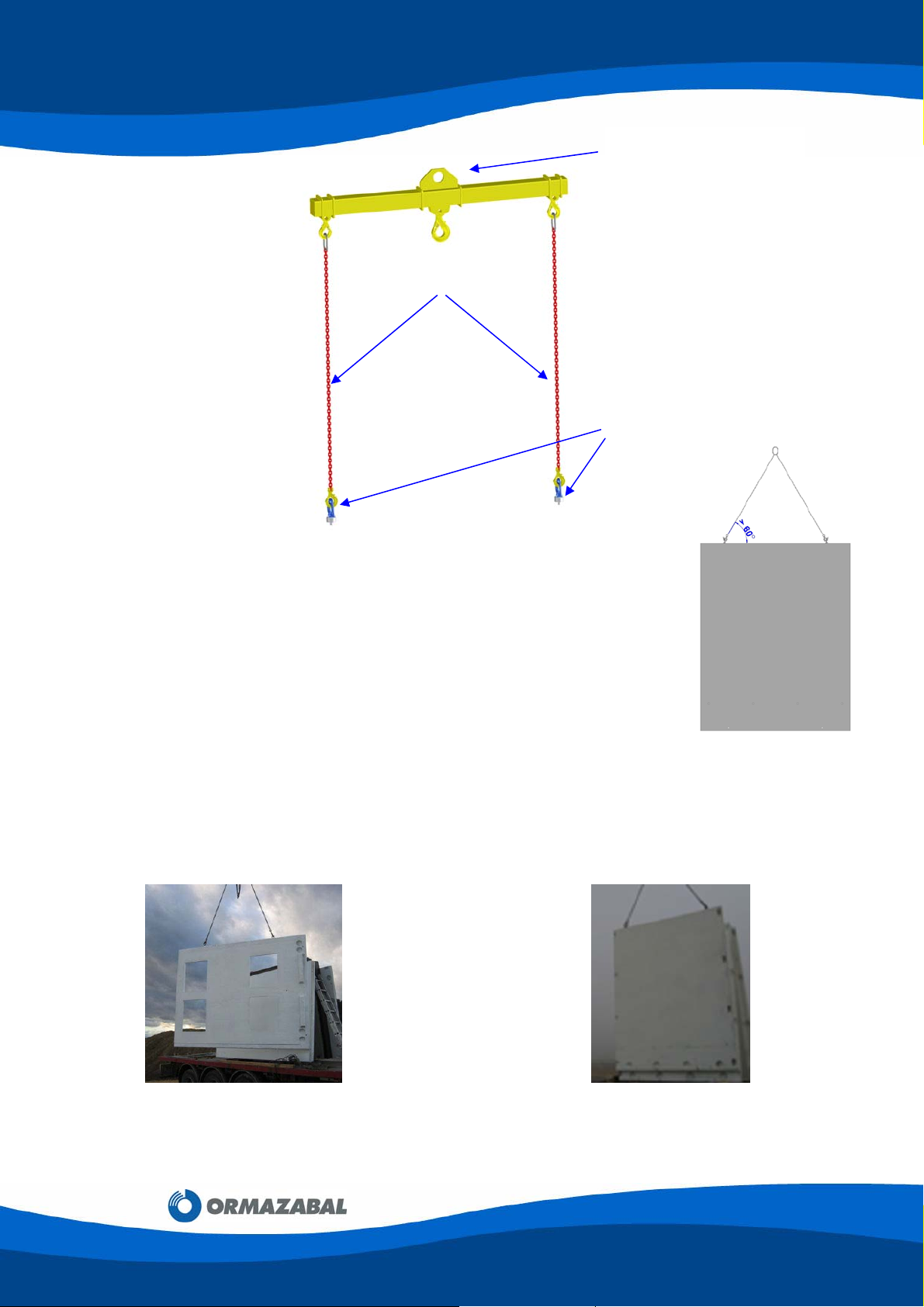
Handling the concrete components correctly requires the following tools:
• Lifting beam (reference 160023, “PF 4 T Unloading Beam”)
• Sling set (reference 160024, “PF Unloading Slings”)
• Turning Eyebolts RD20 (reference160027)
4848
Page 13 of 48
GENERAL INSTRUCTIONS FOR PF
d
MODULAR ENCLOSURES FOR
TRANSFORMER SUBSTATIONS
PF 4 T Unloading Beam
PF Unloading Slings
ref 160024
Turning Eyebolts RD20
Figure 3.5: Panel handling tools
To lift the components as evenly as possible, the lifting beam should be used
to handle all the concrete components.
The chains' angle of pull should be as vertical as possible (at least 60º from
horizontal).
Figure 3.6: Angle from the horizontal > 60º
3.5.1. PF-200 / 300 & PF-2015 / 3015 SERIES CONCRETE COMPONENTS
ref. 160023
ref 160027
IG-021-GB
version 07
29.08.2008
PF enclosure concrete components have RD20 threaded inserts embedded in the concrete;
therefore, the components can be lifted and handled with a crane by anchoring RD20
threaded turning eyebolts.
Figure 3.7: 200 series side panel transported horizontally an
handled with threaded eyebolts
Figure 3.8: 200 series front panel transported vertically
and handled with threaded eyebolts
Page 14 of 48

IG-021-GB
version 07
29.08.2008
Figure 3.9: Anchoring with threaded turning eyebolts
3.6. ASSEMBLING TOOLS
GENERAL INSTRUCTIONS FOR PF
MODULAR ENCLOSURES FOR
TRANSFORMER SUBSTATIONS
Proper assembly of the PF Modular Transformer Substations requires the following elements
to be available:
PF Assembling Prop (reference 160028)
The number of required props depends on the number of modules forming the
enclosure. PF-203 requires 3 props; PF-304 requires 4 props; PF-305 requires 5
props, etc.; therefore, the number of required props equals the number of modules
making up the enclosure.
1 ratchet wrench set
1 low-profile ratchet wrench (reference 394253-31, ‘PF Assembling Ratchet’)
2 ladders
1 brush
1 set of spanners and screwdrivers
Painting utensils, for painting the transformer substation or for retouching painted
panels.
For correct assembly of the panels, the enclosure foundations must be levelled with the
greatest care according to the instructions in section 3.4.
3.7. PF ENCLOSURE ASSEMBLY PROCESS
By way of example, the assembly process for a PF-205 enclosure with 2 transformers and
1 personnel access door is explained below.
The panels used to assemble the PF Modular Transformer Substations are grouped into two
classes, according to how they are assembled:
a) Horizontally-assembled panels: These are the bottom plates, floor plates and
covers.
b) Vertically-assembled panels: These are the front, back and side panels.
4848
Page 15 of 48
 Loading...