

Ormazabal ekor.rpa, ekor.rpa-110, ekor.rpa-110-v, ekor.rpa-120, ekor.rpa-110-p General Instructions Manual
...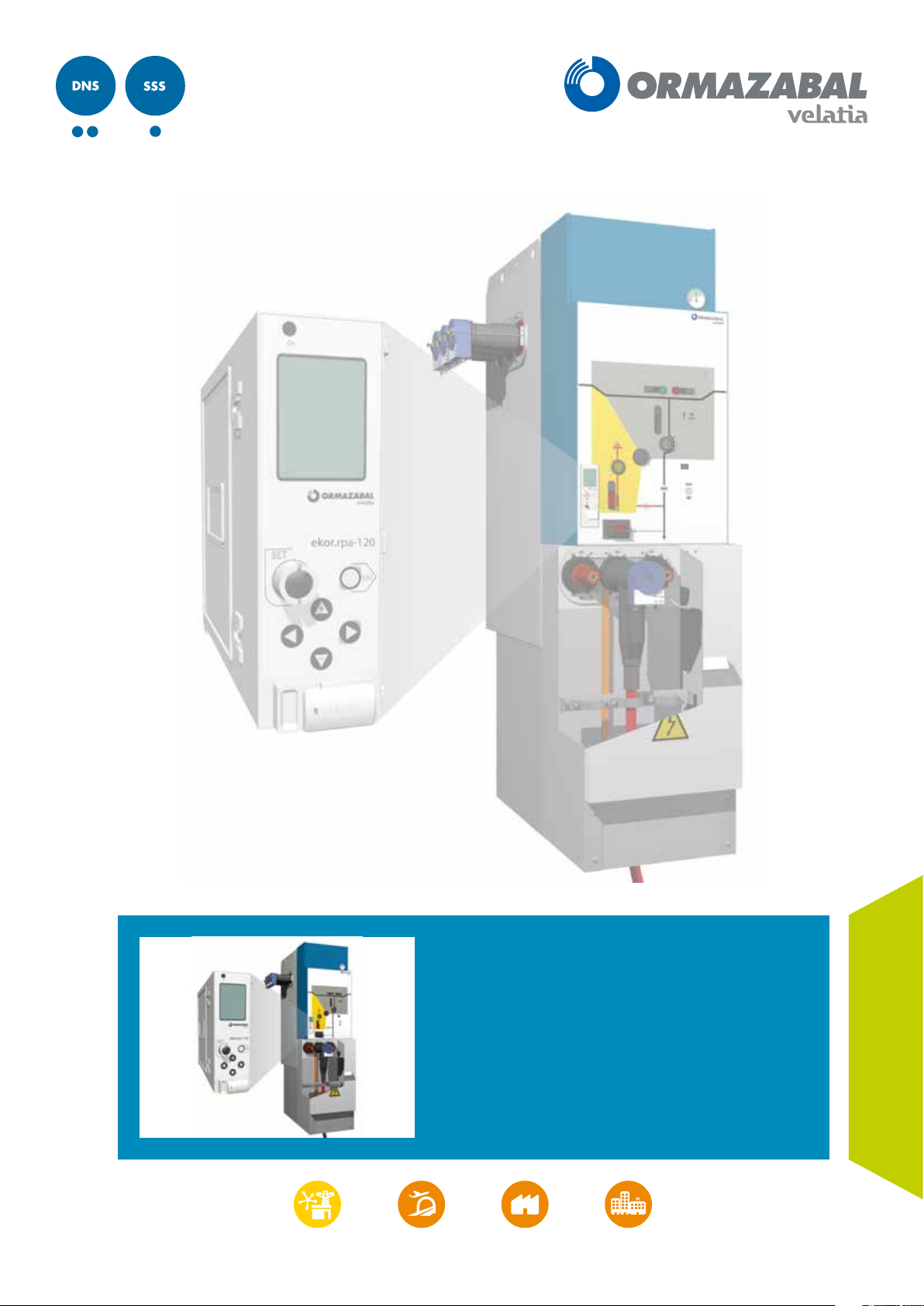
ekor.rpa
Protection, metering and control
multifunction unit
General Instructions
IG-267-EN, version 01, 07/04/2017
LIB

CAUTION!
When medium-voltage equipment is operating, certain components are live, other parts may be in movement and some may
reach high temperatures. Therefore, the use of this equipment poses electrical, mechanical and thermal risks.
In order to ensure an acceptable level of protection for people and property, and in compliance with applicable environmental
recommendations, Ormazabal designs and manufactures its products according to the principle of integrated safety, based on
the following criteria:
• Elimination of hazards wherever possible.
• Where elimination of hazards is neither technically nor economically feasible, appropriate protection functions are
incorporated in the equipment.
• Communication about remaining risks to facilitate the design of operating procedures which prevent such risks,
training for the personnel in charge of the equipment, and the use of suitable personal protective equipment.
• Use of recyclable materials and establishment of procedures for the disposal of equipment and components so
that once the end of their service lives is reached, they are duly processed in accordance, as far as possible, with the
environmental restrictions established by the competent authorities.
Consequently, the equipment to which the present manual refers complies with the requirements of section 11.2 of Standard
IEC 62271-1. It must therefore only be operated by appropriately qualified and supervised personnel, in accordance with the
requirements of standard EN 50110-1 on the safety of electrical installations and standard EN 50110-2 on activities in or near
electrical installations. Personnel must be fully familiar with the instructions and warnings contained in this manual and in other
recommendations of a more general nature which are applicable to the situation according to current legislation
The above must be carefully observed, as the correct and safe operation of this equipment depends not only on its design but also
on general circumstances which are in general beyond the control and responsibility of the manufacturer. More specifically:
• The equipment must be handled and transported appropriately from the factory to the place of installation.
• All intermediate storage should occur in conditions which do not alter or damage the characteristics of the equipment
or its essential components.
• Service conditions must be compatible with the equipment rating.
• The equipment must be operated strictly in accordance with the instructions given in the manual, and the applicable
operating and safety principles must be clearly understood.
• Maintenance should be performed properly, taking into account the actual service and environmental conditions in
the place of installation.
The manufacturer declines all liability for any significant indirect damages resulting from violation of the guarantee, under any
jurisdiction, including loss of income, stoppages and costs resulting from repair or replacement of parts.
[1]
.
Warranty
The manufacturer guarantees this product against any defect in materials and operation during the contractual period. In the
event that defects are detected, the manufacturer may opt either to repair or replace the equipment. Improper handling of this
equipment and its repair by the user shall constitute a violation of the guarantee.
Registered Trademarks and Copyrights
All registered trademarks cited in this document are the property of their respective owners. The intellectual property of this manual
belongs to Ormazabal.
[1]
For example, in Spain the “Regulation on technical conditions and guarantees for safety in high-voltage electrical installations” – Royal Decree
337/2014 is obligatory.
In view of the constant evolution in standards and design, the characteristics of the elements contained in this manual are subject
to change without prior notice. These characteristics, as well as the availability of components, are subject to confirmation by
Ormazabal.

General Instructions
ekor.rpa
Contents
Contents
1. General description ..................................................5
1.1. General operating features ...................6
1.2. Components.................................7
1.2.1. Electronic relay ..............................8
1.2.2. Current sensors ..............................9
1.2.3. Voltage sensors ..............................9
1.2.4. “Binox” bistable tripping device and
tripping coil ................................10
1.3. Functionality of the unit.....................10
1.4. Communications............................11
2. Applications .............................................................12
2.1. Remote control of transformer and
distribution substations .....................12
2.2. Automatic reclosing of lines .................12
2.3. Line protection with circuit-breaker..........13
2.4. Transformer protection......................14
2.5. Automatic transfer . . . . . . . . . . . . . . . . . . . . . . . . . .16
2.6. Detection of phase with earthing............16
2.7. Protection and control of
MV interconnection stations.................17
2.8. Energy balances ............................17
3. Metering functions ..................................................18
3.1. Current and voltage metering ...............18
3.2. Power meterings............................19
3.3. Energy meter ...............................19
4. Protection functions ................................................20
4.1. Overcurrent units ...........................20
4.1.1. Timed overcurrent units.....................20
4.1.2. Instantaneous overcurrent units.............21
4.1.3. Block diagram ..............................21
4.2. Ultra-sensitive earth.........................22
4.3. Directional units ............................23
4.3.1. Phase directional units ......................23
4.3.2. Neutral and sensitive neutral
directional units ............................24
4.4. Thermal image unit .........................25
4.4.1. Estimated thermal capacity..................26
4.4.2. Functionality................................27
4.4.3. Block diagram ..............................28
4.5. Broken conductor unit ......................29
4.5.1. Calculation of sequence currents ............29
4.5.2. Functionality................................32
4.5.3. Block diagram ..............................32
4.6. Voltage units ...............................33
4.6.1. Timed overvoltage units ....................34
4.6.2. Instantaneous overvoltage units.............34
4.6.3. Timed undervoltage units...................35
4.6.4. Instantaneous undervoltage units ...........35
4.6.5. Block diagram ..............................36
4.7. Second harmonic blocking unit .............37
4.7.1. Functionality................................37
4.7.2. Block diagram ..............................39
4.8. Block by I
5. Detection, automation and control functions .......42
5.1. Recloser automation ........................42
5.1.1. Functionality................................42
5.1.2. VREF........................................42
5.1.3. Settings ....................................43
5.1.4. Recloser statuses............................43
5.2. Voltage presence/absence automation ......45
5.2.1. Functionality................................45
5.2.2. Settings ....................................45
5.2.3. Voltage presence/absence
automation statuses ........................45
5.3. Switch control ..............................46
5.3.1. Introduction . . . . . . . . . . . . . . . . . . . . . . . . . . . . . . . .46
5.3.2. Settings ....................................46
5.3.3. Switch control statuses......................47
5.4. Remote control .............................47
6. Sensors ......................................................................48
6.1. Current sensors .............................48
6.1.1. Functional characteristics
of current sensors...........................49
6.1.2. Vector sum/zero-sequence wiring ...........50
6.2. Voltage sensors .............................51
6.2.1. Bushing ....................................51
6.2.2. ekor.evt-c ..................................52
7. Technical characteristics of the equipment ...........53
7.1. Rated values ................................53
7.2. Mechanical design ..........................53
7.3. Insulation tests..............................54
7.4. Electromagnetic compatibility...............54
7.5. Climatic tests ...............................55
7.6. Mechanical tests ............................55
7.7. Power tests .................................55
7.8. CE Conformity ..............................55
.................................41
max
IG-267-EN versión 01; 07/04/2017
3

Contents General Instructions
ekor.rpa
8. Protection, metering and control models .............56
8.1. Description of models vs functions ..........56
8.1.1. ekor.rpa-110................................58
8.1.2. ekor.rpa-120................................58
8.1.3. ekor.rpa-100-v/ekor.rpa-100-p..............59
8.1.4. Relay configurator ..........................60
8.2. “v” ekor.rpa-110-v and ekor.rpa-120-v
type units...................................61
8.2.1. Functional description ......................61
8.2.2. Definition of digital inputs/outputs .........62
8.2.3. Installation in a cubicle......................63
8.2.4. Checking and maintenance .................64
8.3. “p” ekor.rpa-110-p and ekor.rpa-120-p
type units ..................................66
8.3.1. Functional description ......................66
8.3.2. Definition of digital inputs/outputs ..........67
8.3.3. Fuse protection . . . . . . . . . . . . . . . . . . . . . . . . . . . . .68
8.3.4. Installation in a cubicle......................71
8.3.5. Checking and maintenance .................72
9. User configuration settings .....................................73
9.1. Local protection and automation settings ...73
9.2. Date and time settings ......................79
9.3. Remote communication settings ............79
11. User interface ...........................................................85
11.1. Web server. Checking and
configuring parameters .....................85
11.1.1. Characteristics of the Web server ............85
11.1.2. Access to the Web server: Local and
remote access ..............................86
11.2. Keyboard/Display ..........................90
11.2.1. Introduction . . . . . . . . . . . . . . . . . . . . . . . . . . . . . . . .90
11.2.2. Display screen ..............................91
11.2.3. Error codes .................................96
11.3. Fileserver in USB memory ...................97
11.3.1. Connection to the system ...................97
11.3.2. Use of the interface .........................98
11.3.3. ekor.soft-xml ............................. 100
12. Communications ................................................... 102
12.1. Physical medium: RS-485.................. 102
12.1.1. MODBUS protocol ........................102
12.1.2. PROCOME protocol .......................107
12.2. Physical medium: Ethernet ................110
12.3. Physical medium: Mini-USB................111
13. Annex ..................................................................... 112
10. Log record .................................................................80
10.1. Fault report ................................80
10.1.1. Data capture logic ..........................80
10.1.2. Structure of the report ......................81
10.1.3. List of available signals .....................82
10.2. Event record ................................84
4
IG-267-EN versión 01; 07/04/2017
General Instructions
ekor.rpa
1. General description
General description
Within the ekor.sys family, the ekor.rpa range of protection,
metering and control units groups together a series of
multifunctional devices. Depending on the model, the
equipment can incorporate voltage and current functions,
along with automation functions, local/remote control,
etc. All these functions are related to current and future
automation, control and protection requirements in
switching and transformer substations.
As a result of new demands in supply quality, there is an
increasing need for automation in distribution networks
and for equipment to carry out metering and control
supervision functions for the switch in distribution cubicles.
The ekor.rpa-100 protection, metering and control units
have been designed to meet these needs, in accordance
with national and international standard requirements and
recommendations that are applied to each part that makes
up the unit:
• EN 60255, EN 61000, EN 62271-200, EN 60068, EN 60044.
• IEC 60255, IEC 61000, IEC 62271-200, IEC 60068, IEC 60044,
IEC 61958.
Integrating the ekor.rpa units in the Ormazabal cubicle
system allows specific products for requirements in different
facilities.
2. Delivering the complete integrated solution (cubicle +
relay + sensors) reduces handling of interconnections
when installing the cubicle in the network connection.
The only connection necessary is the medium-voltage
cables (MV). The possibility of wiring and installation
errors is removed, thus minimising commissioning time.
3. Voltage and current sensors are installed in the cubicle
cable bushing. Metering of V, I, P, Q and energies are
obtained without the need for voltage transformers.
4. All the units are factory installed, adjusted and checked;
each piece of equipment (relay + control + sensors)
also undergoes a comprehensive check before being
installed. The final unit tests are carried out once the
unit is incorporated in the cubicle before delivery.
5. Current metering is carried out by current sensors
with a high transformation ratio, making it possible for
the same equipment to detect a wide range of power
levels. This is possible thanks to the high sensitivity and
low noise of the relay's analogue channels.
The ekor.rpa-100 units in the ekor.rpa range have outputs
to, either locally or remotely, open and close the switch
in the cubicle where it is installed. Furthermore, the
equipment series has inputs which receive the status of the
cubicle switch.
The ekor.rpa-100 units also have the following benefits
compared to conventional systems:
1. The remote control unit (RTU or Remote Terminal Unit)
and protection are integrated in the cubicle in a compact
manner, simplifying the solution and minimising the
need to install control boxes on the cubicles.
Figure 1.1. Protection, metering and control units: ekor.sys family
IG-267-EN versión 01; 07/04/2017
5
General description General Instructions
ekor.rpa
1.1. General operating features
All the relays of the ekor.rpa-100 series include a
microprocessor for processing the metering sensor signals.
They process voltage and current meterings and eliminate
the influence of transient states, calculate the magnitudes
required to ensure current and voltage protection functions,
automation, etc. At the same time they calculate the
efficient values of the electrical meterings that report the
instantaneous value of these parameters of the installation.
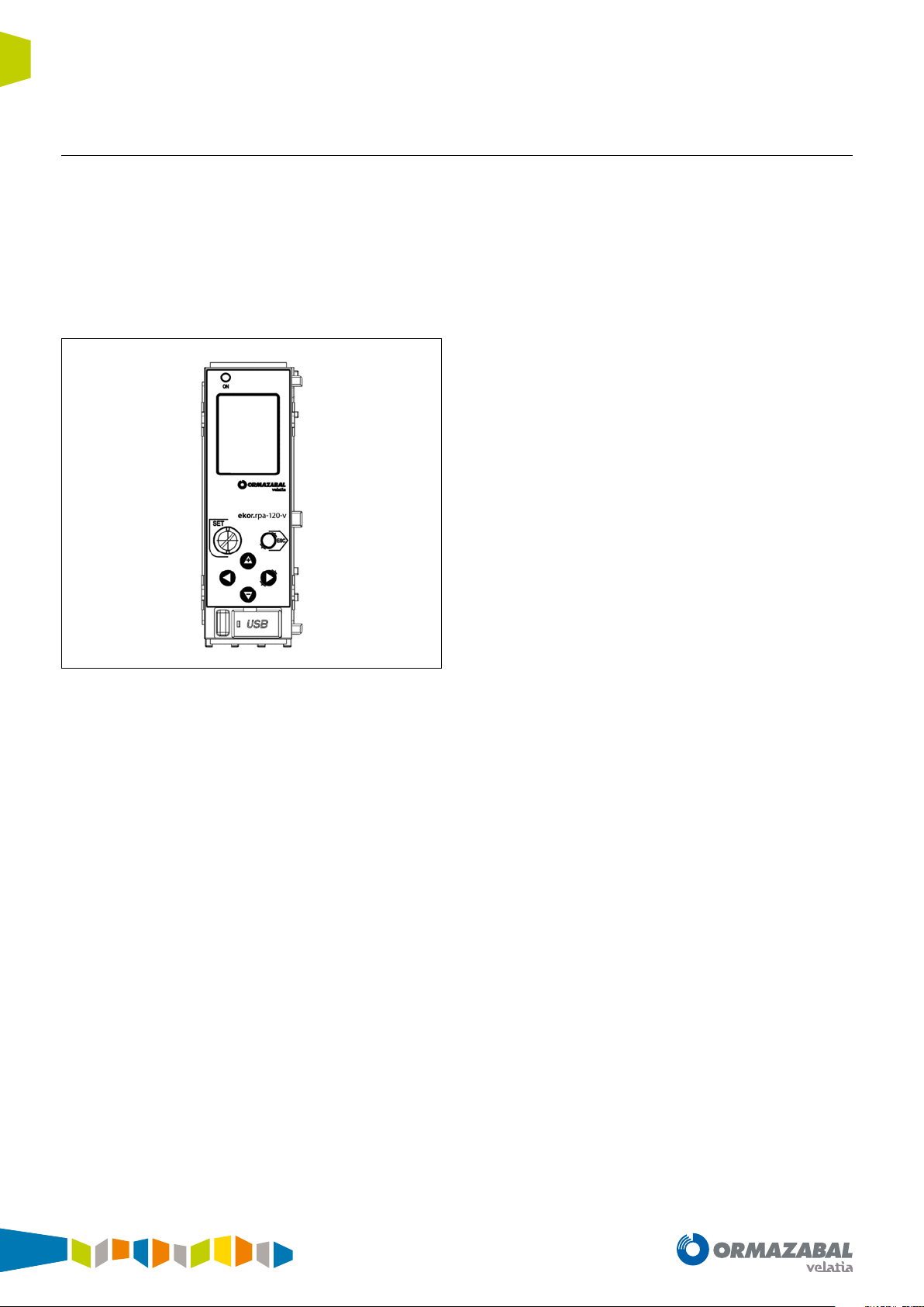
Figure 1.2. ekor.rpa-100 series relay
The ekor.rpa-100 relays are equipped with a keypad for
local display, set-up and operation of the unit, as well as
communication ports to handle these functions from a PC,
either locally or remotely. The ergonomic keyboard menus
have been designed to make use as intuitive as possible.
Current metering is carried out via high transformation
ratio current sensors. These transformers or current sensors
maintain the accuracy class in all of their rated range.
Voltage metering is normally by capturing the voltage
signal using a capacitor divider built into the cubicle's
bushing. There is an option of installing ekor.evt-c external
capacitive voltage sensors for applications which require
high-voltage metering precision, such as applications with
MV network energy meters.
The different interfaces, local (display) or remote (Web), also
provide settings parameters, logs, events, etc., in addition
to instantaneous values for metering of currents, voltages,
powers and energies.
From a maintenance perspective, the ekor.rpa-100 units
have a series of features that reduce the time and the
possibility of errors in the test and service restoration tasks.
Among the main characteristics, the most prominent are
the large diameter toroidal-core current transformers
installed in the cubicle bushing, their built-in test bars
(for easier checking), and accessible terminal blocks for
current or voltage injection tests as well as for checking
the relay inputs and outputs. This configuration enables a
comprehensive testing of the unit.
6
IG-267-EN versión 01; 07/04/2017
General Instructions
ekor.rpa
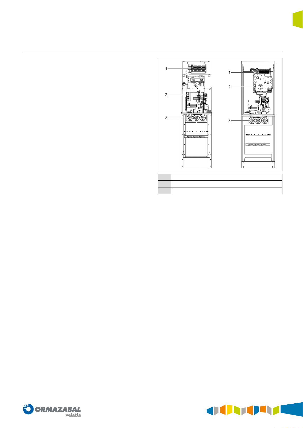
1.2. Components
The parts which make up the ekor.rpa-100 protection,
metering and control series are the electronic relay, voltage
and current sensors, auxiliary circuits (terminal block and
wiring), the bistable release and the tripping coil.
General description
Terminal block
1
ekor.rpa electronic relay
2
Voltage and current sensors
3
Figure 1.3. Parts of the assembly of ekor.rpa-100 in cubicle
IG-267-EN versión 01; 07/04/2017
7
General description General Instructions
ekor.rpa
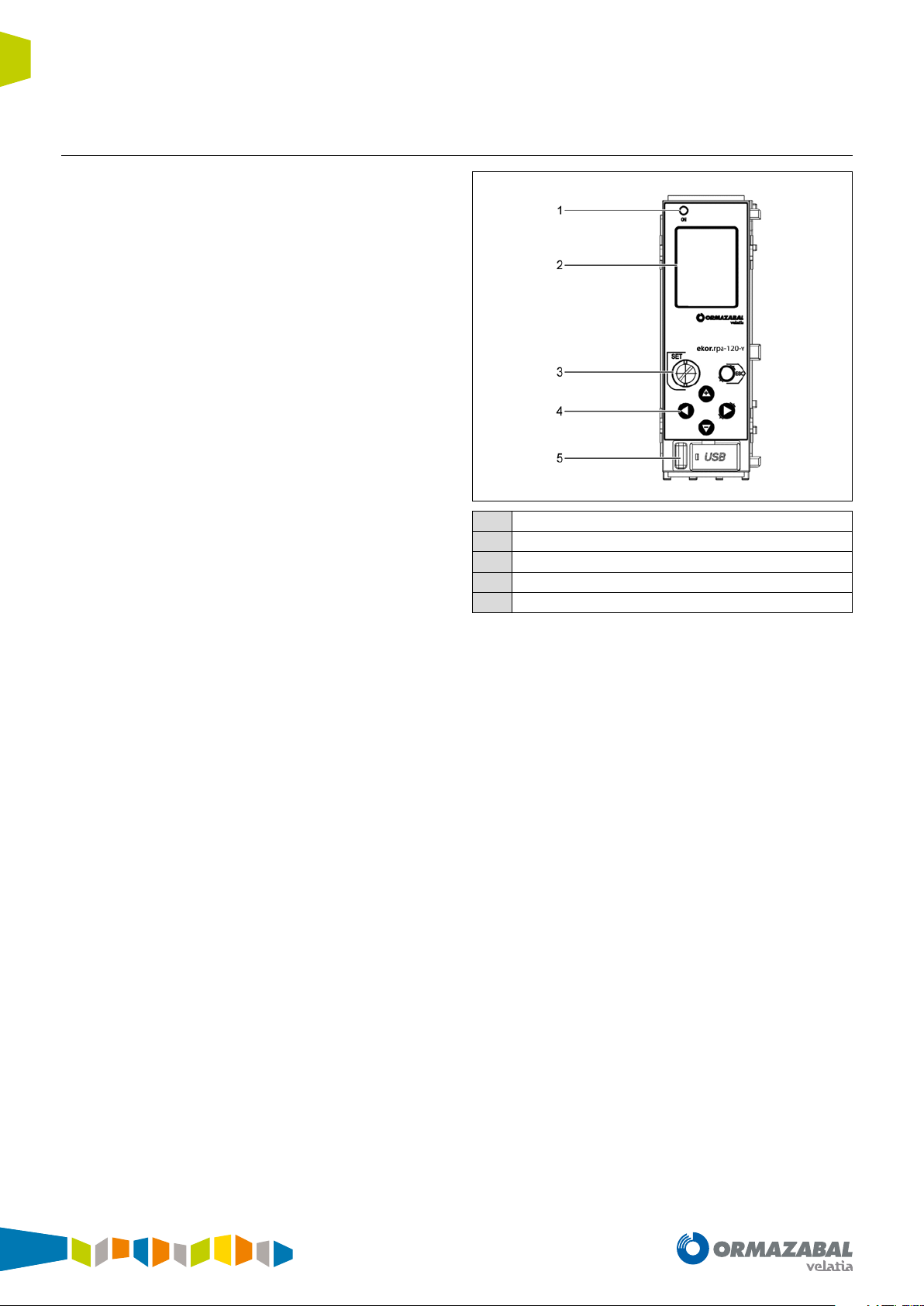
1.2.1. Electronic relay
The electronic relay has a keyboard and display to set and
view the protection and control parameters. Moreover, the
display provides information of the system's meterings,
alarms and control signals in real time. The keyboard
includes a seal on the <<SET>> key to ensure that once the
settings have been made they cannot be changed unless
the seal is broken.
The protection trips are registered on the display with the
following parameters:
• Trip unit
• The phasor at the moment of tripping (currents and
voltages).
• Tripping time. The time passing from start-up to tripping
of the unit.
• The time and date the event occurred.
Unit errors are also permanently displayed. Furthermore, it
is possible to check the fault reports using the front USB port
by connecting a PC to this port and using the implemented
folder system.
The “ON” LED is activated when the equipment receives
power from an external source and flashes quickly when
the relay starts up. This LED will flash less frequently
once the microprocessor has checked that the status of
the equipment is correct and all the protection units are
active. In this situation, the unit is operational to carry out
protection functions.
The voltage and current analogue signals are conditioned
internally by small and very accurate transformers that
isolate the electronic circuits from the rest of the installation.
The system has, in all its variants, 9 inputs and 4 outputs.
Both the inputs and the outputs are protected from
unwanted enabling/disabling.
The unit has 2 rear Ethernet ports for configuration, a
front mini-USB port for maintenance, and two rear RS-485
communications ports for remote control. The standard
communication protocols for all models are MODBUS and
PROCOME.
"ON" signalling LED
1
Metering and parameter setting display
2
SET key
3
Keyboard for scrolling through screens
4
Front mini-USB communication port
5
Figure 1.4. Description of the elements available on the front of the
ekor.rpa-120 relay
8
IG-267-EN versión 01; 07/04/2017

General Instructions
ekor.rpa
1.2.2. Current sensors
The current sensors are toroidal-core current transformers
with a 300/1 A or 1000/1 A or 2500/1 ratio, depending on
the models. These transformers cover the entire operation
range of Ormazabal cubicles, from rated currents 5A up to
2500 A.
The phase toroidal transformers are factory-installed in
the cubicle bushings, which significantly simplifies on-site
assembly and connection. This way, once the mediumvoltage cables are connected to the cubicle, the installation
protection is operational. Installation errors of the sensors,
due to earth grids, polarities, etc., are removed upon
installation and checked directly at the factory.
All the current sensors have an integrated protection
against the opening of secondary circuits, which prevents
overvoltages.
General description
1.2.3. Voltage sensors
Cubicle voltage metering is carried out using a capacitor
divider incorporated in the cubicle’s bushing, which ensures
a precision of ± 5 % in the worst case scenario.
Ormazabal ekor.evt-c capacitive sensors can be used
for greater precision. These are capacitor divider voltage
sensors for gas-insulated cubicles. They are designed to
allow assembly in both separable T-connectors and busbars.
Their operation is autonomous and passive (without
external auxiliary supply), with low-voltage analogue
output and low power applicable directly to the metering
systems without prior conditioning, for installation in
medium-voltage automation and supervision systems in
networks up to 36 kV. It can also measure partial discharges
and establish communication via PLC.
Bushing
1
Current sensors
2
Figure 1.5. Location of the current sensors
Figure 1.6. ekor.evt-c voltage sensors
IG-267-EN versión 01; 07/04/2017
9

General description General Instructions
ekor.rpa
1.2.4. “Binox” bistable tripping device and tripping coil
The "Binox" bistable trigger is a precision electromechanical
actuator which is sealed with its own reinforcement and
integrated in the switch driving mechanism. This release
acts upon the switch when there is a protection trip. It is
characterised by the low actuation power (high energy
efficiency) it requires for tripping. This energy is delivered in
the form of a pulse from the relay in a controlled manner to
ensure the proper operation of the release and the opening
of the switch.
The trials and tests passed by the ekor.rpa-100 unit set and
cubicle, along with quality assurance in manufacture, mean
this is a highly reliable element in the tripping chain. The
solutions presented by Ormazabal with ekor.rpa-100 units
have this tripping device installed as standard.
Figure 1.7. “Binox” Tripping coil
The operations ordered by the ekor.rpa-100 unit digital
outputs are performed by means of conventional tripping
coils. This way, a redundant and therefore more reliable
operational system is achieved.
1.3. Functionality of the unit
The functionality of the assembly as a unit (MV cubicles for
protection, metering and control, sensors, and protection
and metering transformers) is validated in a test plan carried
out in an in-house controlled environment.
To achieve this, Ormazabal counts on the CIT, its Research
and Technology Centre, which represents an essential
instrument in R&D, in order to capture and improve existing
technologies and carry out research into new ones.
The CIT facilities offer services to the science and technology
sector in order to carry out research, development and type
tests both for Ormazabal's business unit products and also
for the rest of the electricity sector.
The CIT is made up mainly of:
1. HPL: Electrotechnical power laboratory, with the goal
of identifying, acquiring and disseminating process
technologies and strategic products within Ormazabal.
2. UDEX: Demonstration and experimentation unit
consisting of a fully configurable, independent
medium-voltage singular experimentation network to
allow tests for new technologies, products and services
to be developed and carried out in a safe, controlled
environment.
10
IG-267-EN versión 01; 07/04/2017
General Instructions
ekor.rpa
1.4. Communications
All the relays of the ekor.rpa-100 units have two TCP/IP
connection Ethernet ports and a Web server for
configuration. They also have a front mini-USB port for
maintenance and two rear ports with serial communication
RS-485 twisted pair (COM0 and COM1) for remote control.
The standard communication protocols implemented in all
equipment are MODBUS in RTU transmission mode (binary)
and PROCOME, through the rear RS-485 COM0 port fitted in
these units.
Optionally, the ekor.rpa-120 model also has a bus for
temperature sensor connection.
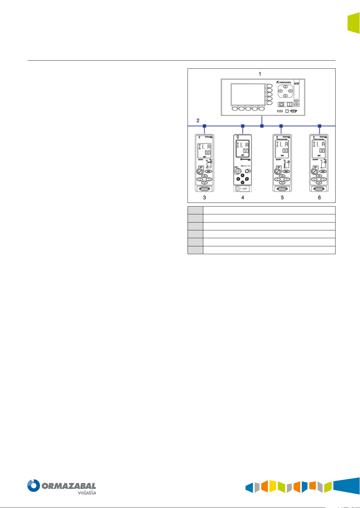
The ekor.rpa-100 relays can be interconnected to other
units in the ekor.sys family, as shown in the image below.
General description
ekor.ccp
1
ekor.bus
2
ekor.rci
3
ekor.rpa
4
ekor.rpt
5
ekor.rpg
6
Figure 1.8. Intercommunicated units of the ekor.sys family
IG-267-EN versión 01; 07/04/2017
11
Applications General Instructions
ekor.rpa
2. Applications
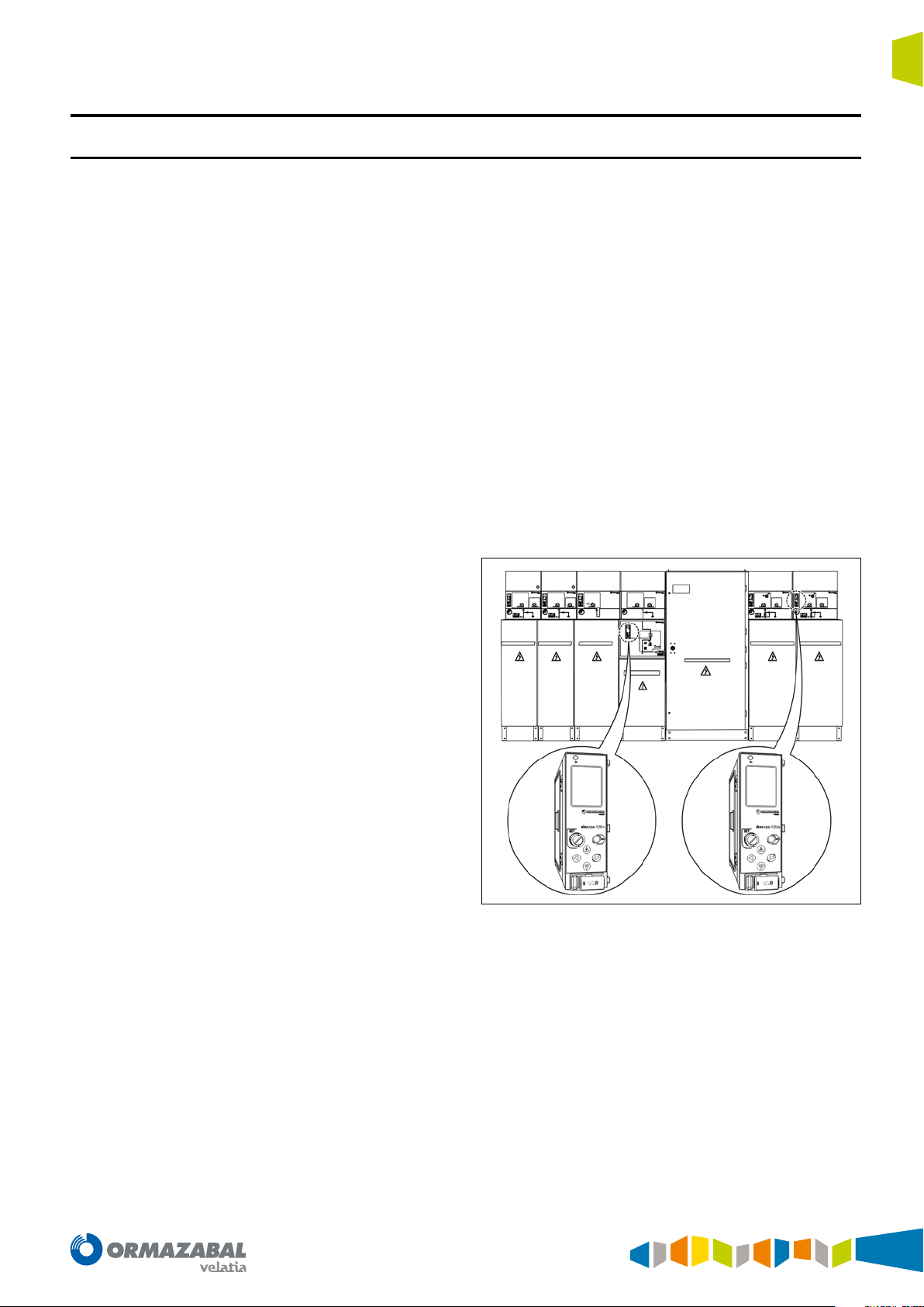
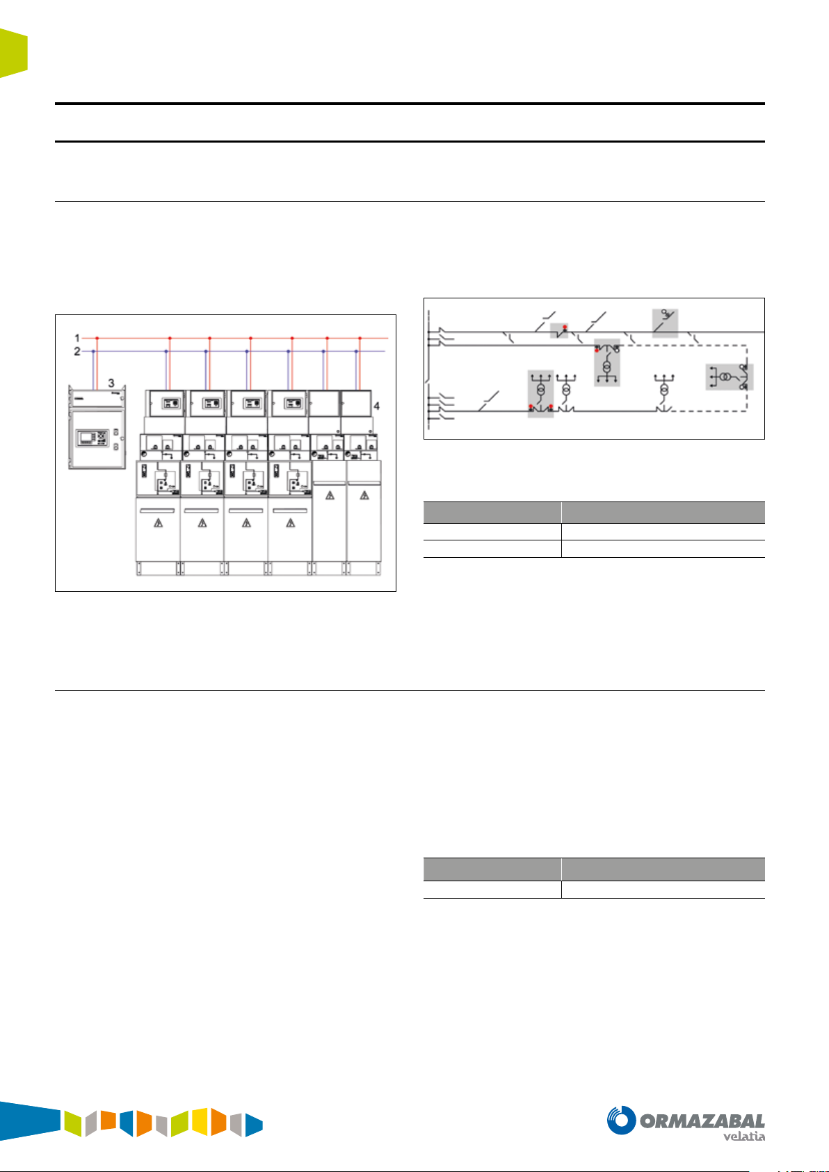
2.1. Remote control of transformer and distribution substations
The ekor.rpa-100 protection, metering and control units
make it possible to handle remote control applications of the
transformer and switching substations, by implementing
the control and monitoring of each switch through the
units associated with each functional unit.
Figure 2.1. Remote-controlled switching substation
The use of a remote control terminal and ekor.rpa-100 units
enable the user to visualise and operate each functional
unit remotely thanks to the inputs and outputs fitted for
this purpose.
Figure 2.2. Layout of dierent stations in the network
Units that include this remote control function:
Unit Type of cubicle
ekor.rpa-100 type = p
ekor.rpa-100 type = v
Table 2.1. Remote control function units
Fuse-combination switch
Circuit-breaker
The remote controlling applications complement the
ekor.rci integrated control unit associated to feeder
functions (see Ormazabal document IG-158).
2.2. Automatic reclosing of lines
The reclosing function performs the automatic reclosing of
lines once the protection unit has commanded the trip and
the switch has opened.
This function is always associated with Ormazabal circuitbreaker cubicles.
The protection units with automatic reclosing have a series
of advantages over protections without reclosing:
• They reduce the time in which electrical power is
interrupted.
• They avoid the need to locally re-establish the service in
substations without remote control for transient faults.
• They reduce the fault time using a combination of fast
switch trips and automatic reclosings, which results in
lesser damage caused by the fault and generates a lower
number of permanent faults derived from transient faults.
The unit which includes this function is:
Unit Type of cubicle
ekor.rpa-100 type = v
Table 2.2. Recloser function unit
Circuit-breaker
12
IG-267-EN versión 01; 07/04/2017
General Instructions
ekor.rpa
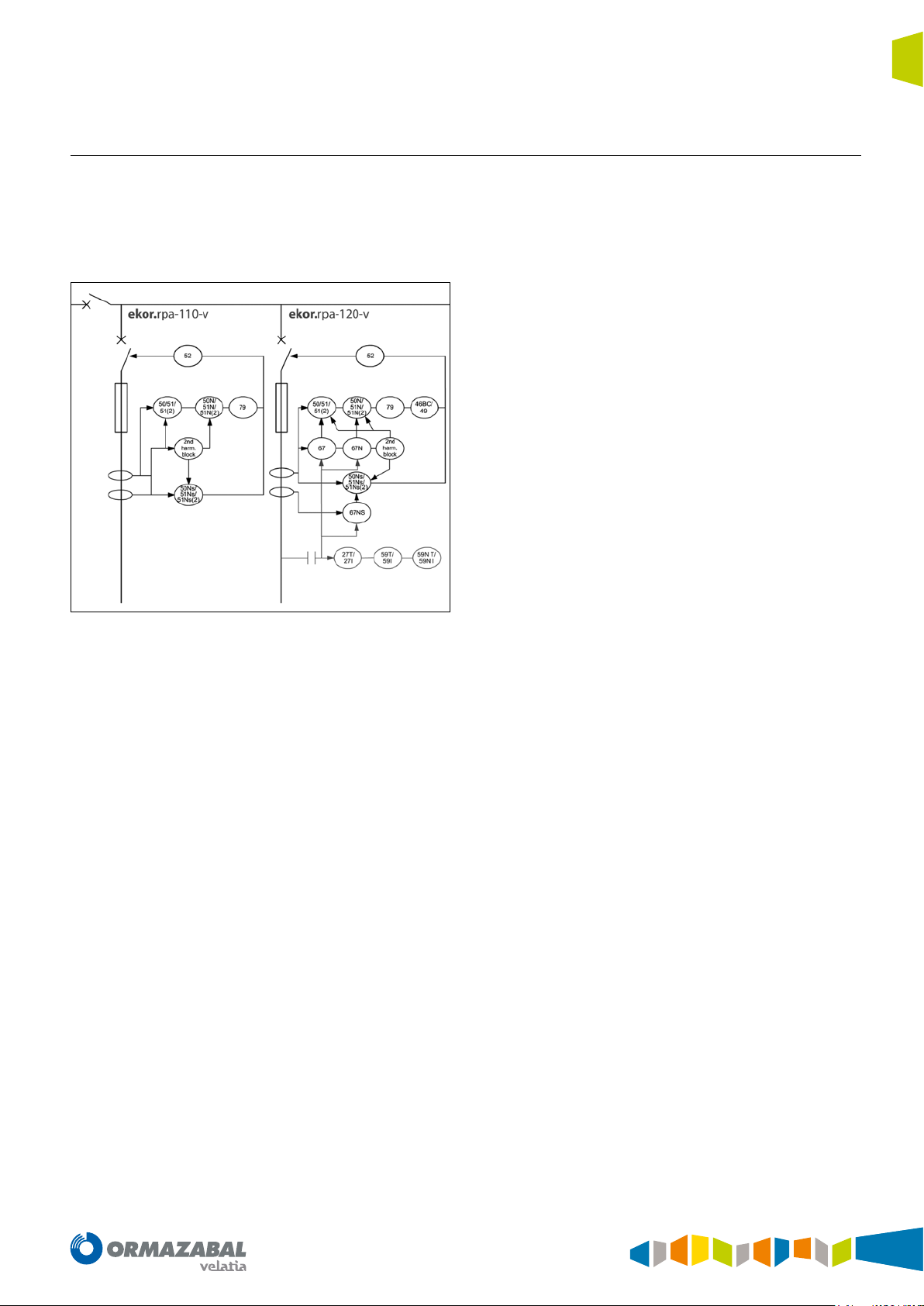
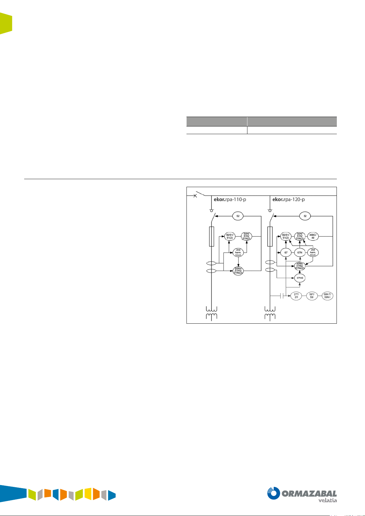
2.3. Line protection with circuit-breaker
Applications
The purpose of the line protection is to isolate this part
of the network in case of fault, without it affecting the
rest of the lines. In a general way, it covers any faults that
originate between the substation, transformer substation
or switching substation and the consumption points.
Figure 2.3. Feeder protection functions in ekor.rpa-100 relays
The types of fault that occur in these areas of the network
depend primarily on the nature of the line, overhead line or
cable and the neutral used.
In networks with overhead lines, the majority of faults are
transient, which makes many line reclosings effective; in
these cases, the reclosing function associated with circuitbreakers is used.
This is not the case for underground cables where faults are
usually permanent.
On the other hand, in case of phase-to-earth faults in
overhead lines, when the ground resistance is very high,
the zero-sequence fault currents have a very low value In
these cases, an ‘ultrasensitive’ neutral current detection is
required.
The underground cables have earth coupling capacities,
which causes the single phase faults to include capacitive
currents. This phenomenon makes detection difficult in
isolated or resonant earthed neutral networks and thus
requires the use of the directional function.
In ekor.rpa-100 units, model ekor.rpa-110, line protection
is carried out mainly by the following functions:
• 50 ≡ Instantaneous overcurrent relay. Protects against
short-circuits between phases.
• 51 ≡ Inverse time overcurrent relay. Protects against
excessive overloads, which can deteriorate the
installation.
• 51_2 ≡ Inverse time overcurrent relay II. Additional
step to protect against excessive overloads, which can
deteriorate the installation.
• 50N ≡ Instantaneous earth overcurrent relay. Protects
against phase-to-earth short-circuits.
• 51N ≡ Inverse time earth overcurrent relay. Protects
against highly resistive faults between phase and earth.
• 51_2_N ≡ Inverse time earth overcurrent relay II.
Additional step to protect against highly resistive faults
between phase and earth.
• 50NS ≡ Instantaneous sensitive earth overcurrent
relay. Protects against phase to earth short-circuits of
very low value.
• 51NS ≡ Inverse time sensitive earth overcurrent
relay. Protects against highly resistive faults between
phase and earth of very low value.
• 51_2_NS ≡ Inverse time sensitive earth overcurrent
relay II. Additional step to protect against highly
resistive faults between phase and earth of very low
value.
nd
• 2
Harm. Block ≡ Second harmonic blocking. Blocks
overcurrent units during transformer magnetisation
• 79 ≡ Reclosing relay. Enables the automatic reclosing
of lines.
IG-267-EN versión 01; 07/04/2017
13
Applications General Instructions
ekor.rpa
In addition, the ekor.rpa-100 equipment, ekor.rpa-120
model, also have the following functions:
• 67/67N and 67NS ≡ Directional overcurrent relay,
directional earth fault relay and directional sensitive
earth fault relay. Phase, neutral and sensitive neutral
directional functions which are associated to their
corresponding overcurrent units, together allowing
directional overcurrent units.
• 49 ≡ Machine or transformer thermal relay. Protects
against thermal overloads in lines which cannot be
detected by the overcurrent units.
• 46BC ≡ Broken conductor detection. Detects open
lines, which are generally quite difficult to detect using
overcurrent units.
2.4. Transformer protection
The distribution transformers require various protection
functions. Their selection depends primarily on the power
and level of responsibility they have in the installation.
• 59/59N ≡ Overvoltage and residual overvoltage
relay. Protects against phase and neutral overvoltages
in the lines with 2 units for each phase and neutral, one
timed and the other instantaneous.
• 27 ≡ Undervoltage relay. Protects against phase
undervoltages in the lines with 2 units for each phase,
one timed and the other instantaneous.
The units which provide the aforementioned functions are:
Unit Type of cubicle
ekor.rpa-100 type = v
Table 2.3. ekor.rpa-100-v
Circuit-breaker
14
Figure 2.4. Transformer protection functions in ekor.rpa-100 relays
IG-267-EN versión 01; 07/04/2017

General Instructions
ekor.rpa
Applications
The protection functions, available in models
ekor.rpa-110, which must be implemented to protect
distribution transformers with power ratings between 160
kVA and 2 MVA are the following:
• 50 ≡ Instantaneous overcurrent relay. Protects against
short-circuits between phases in the primary circuit, or
high value short-circuit currents between phases on the
secondary side. This function is performed by the fuses
when the protection cubicle does not include a circuitbreaker.
• 51 ≡ Inverse time overcurrent relay. Protects
against excessive overloads, which can deteriorate the
transformer, or against short-circuits in several turns of
the primary winding.
• 51_2 ≡ Inverse time overcurrent relay II. Additional
step to protect against excessive overloads, which can
deteriorate the transformer, or against short-circuits in
several turns of the primary winding.
• 50N ≡ Instantaneous earth overcurrent relay. Protects
against phase to earth short-circuits or secondary
winding short-circuits, from the interconnections and
windings in the primary.
• 51N ≡ Inverse time earth overcurrent relay. Protects
against highly resistive faults from the primary circuit to
earth or to the secondary circuit.
• 51_2_N ≡ Inverse time earth overcurrent relay II.
Additional step to protect against highly resistive faults
from the primary circuit to earth or to the secondary.
• 50NS ≡ Instantaneous sensitive earth overcurrent
relay. Protects against phase to earth short-circuits of
very low value.
• 51NS ≡ Inverse time sensitive earth overcurrent
relay. Protects against highly resistive faults between
phase and earth of very low value.
• 51_2_NS ≡ Inverse time sensitive earth overcurrent
relay II. Additional step to protect against highly resistive
faults between phase and earth of very low value. 2
nd
Harm. Block ≡ Second harmonic blocking. Blocks
overcurrent units during transformer magnetisation.
In addition, the ekor.rpa-100 equipment, ekor.rpa-120
models, also have the following functions:
• 67/67N and 67NS ≡ Directional overcurrent relay,
directional earth fault relay and directional sensitive
earth fault relay. Phase, neutral and sensitive neutral
directional functions which are associated to their
corresponding overcurrent units, together allowing
directional overcurrent units.
• 49 ≡ Machine or transformer thermal relay. Protects
against thermal overloads of transformers which cannot
be detected by the overcurrent units.
• 46BC ≡ Broken conductor detection. Detects open
lines. Broken conductors are quite difficult to detect
using overcurrent units.
• 59/59N ≡ Overvoltage relay and residual overvoltage
relay. Protects against phase and neutral overvoltages
in the lines with 2 units for each phase and neutral, one
timed and the other instantaneous.
• 27 ≡ Undervoltage relay. Protects against phase
undervoltages in the lines with 2 units for each phase,
one timed and the other instantaneous.
The protection units that include the above mentioned
functions are:
Unit Type of cubicle
ekor.rpa-100 type = p
ekor.rpa-100 type = v
Table 2.4. ekor.rpa-100-p/ekor.rpa-100-v
Fuse-combination switch
Circuit-breaker
IG-267-EN versión 01; 07/04/2017
15
Applications General Instructions
ekor.rpa
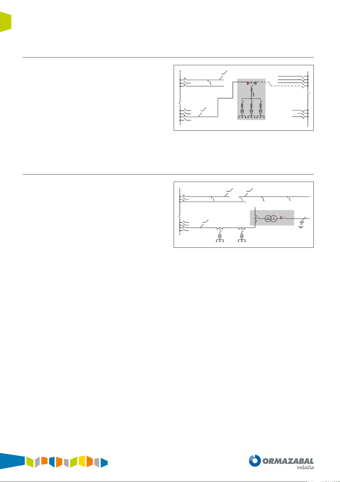
2.5. Automatic transfer
The automatic transfer of lines with circuit-breakers
minimises power outages in loads fed by transformer or
switching substations with more than one incoming line,
thereby improving continuity of service.
Under normal conditions with voltage present on two
possible incoming lines, the switch selected as preferred
remains closed and the reserve one is opened. A voltage
drop in the preferred line will cause the switch of this line
to open and the reserve switch to close afterwards. Once
normality has been re-established in the preferred line, the
inverse cycle is performed, and the system returns to its
initial status.
Figure 2.5. Automatic transfer
2.6. Detection of phase with earthing
In networks with isolated or resonant earthed neutral, the
fault currents are very low. In the event of a fault in a system
of this type, the fault current may not reach the calibrated
threshold for overcurrent protection, and therefore this
fault may not be detected.
Function 59 is used instead of programmed logic for
detecting this type of fault, analysing both the installation’s
neutral voltage and its current.
Figure 2.6. Detection of phase with earthing
16
IG-267-EN versión 01; 07/04/2017
General Instructions
ekor.rpa
2.7. Protection and control of MV interconnection stations
Applications
In MV customers where an ekor.rpa-100 relay is installed,
either in protection cubicles with circuit-breaker or fuses
which protect the MV outgoing, information on this
outgoing can be sent to the SCADA both by the web and
via the MODBUS-TCP communications protocol.
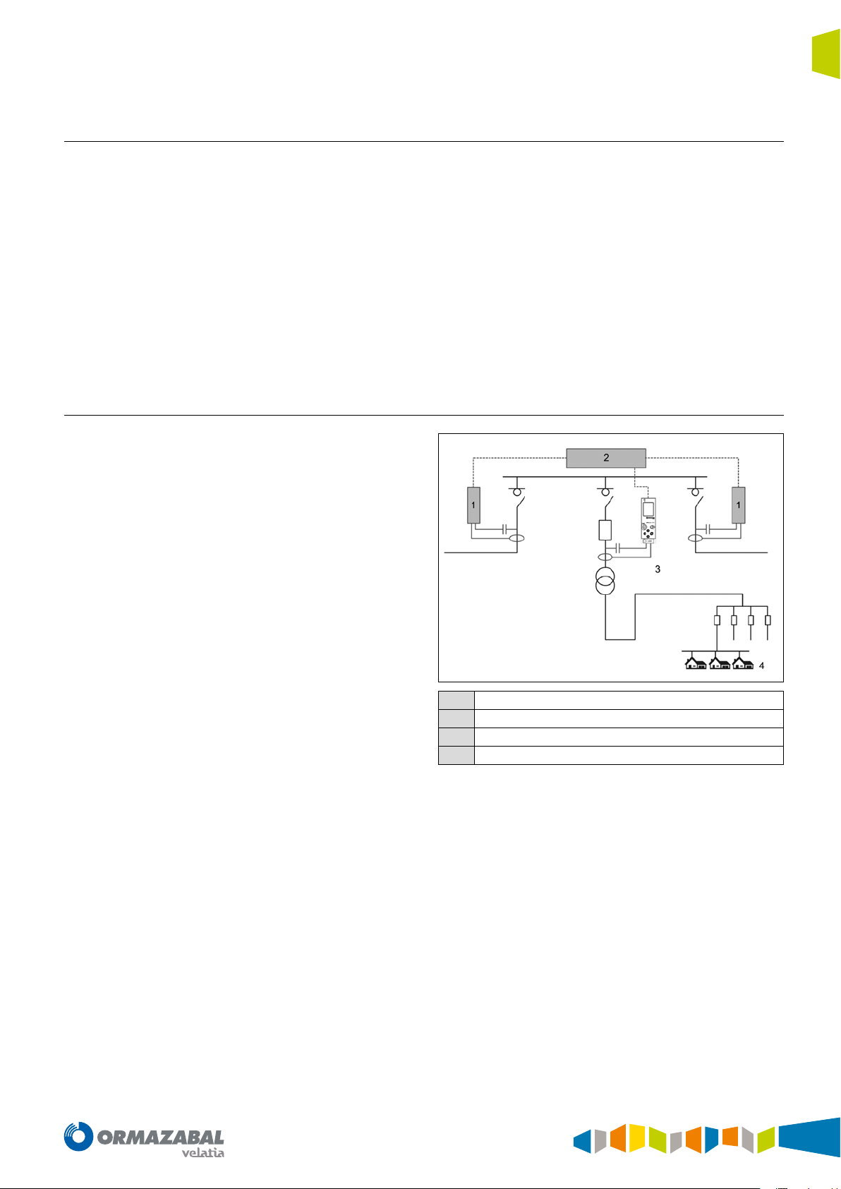
2.8. Energy balances
By including MV energy meterings in the ekor.rpa-100
relays, it is possible to analyse non-technical losses which
can be found between the Transformer Substation and
the LV consumption, in order to uncover possible fraudulent
use such as energy which has not been billed due to an
error in the LV equipment.
The accessible information would be as follows:
• Cubicle position
• Trips
• Alarms
• Meterings:
- Voltage
- Current
- Power
- Energy
ekor.rci
1
ekor.ccp
2
ekor.rpa
3
Meters
4
Figure 2.7. ekor.rpa-100 unit measuring MV energies in a transformer
with private customers
IG-267-EN versión 01; 07/04/2017
17
Metering functions General Instructions
ekor.rpa
3. Metering functions
3.1. Current and voltage metering
The unit has four current reading inputs (IA, IB, IC and INS)
and three voltage reading inputs (VA, VB and VC). Each of
them are conditioned and digitised in order to carry out the
calculation.
The design of the equipment and sensors, along with their
integration in the cubicle, form an assembly which works
as a single unit to achieve maximum immunity and quality
of the signal to be measured, both in the 50 Hz and 60 Hz
networks.
The signal transduction and conditioning stages are
designed to ensure the sensor and relay assembly
reproduces both the magnitude and the phase of the
current and voltage signals of the distribution network.
This ensures optimal performance in real-time applications,
with protection algorithms, in all operation conditions and
in supply quality or load monitoring meterings.
The samples obtained for I
and VN, calculated by the sum
N
of samples of the corresponding phase signals, must be
added to the voltage and current inputs sampled directly.
These calculated signal characteristics are equivalent to
those obtained by vector sum of the conventional sensor
signals.
The meterings for supervision of current and voltage are
measured integrated for 1.28 seconds and represented in
phasorial mode (module + argument). Network load status
is therefore updated regularly.
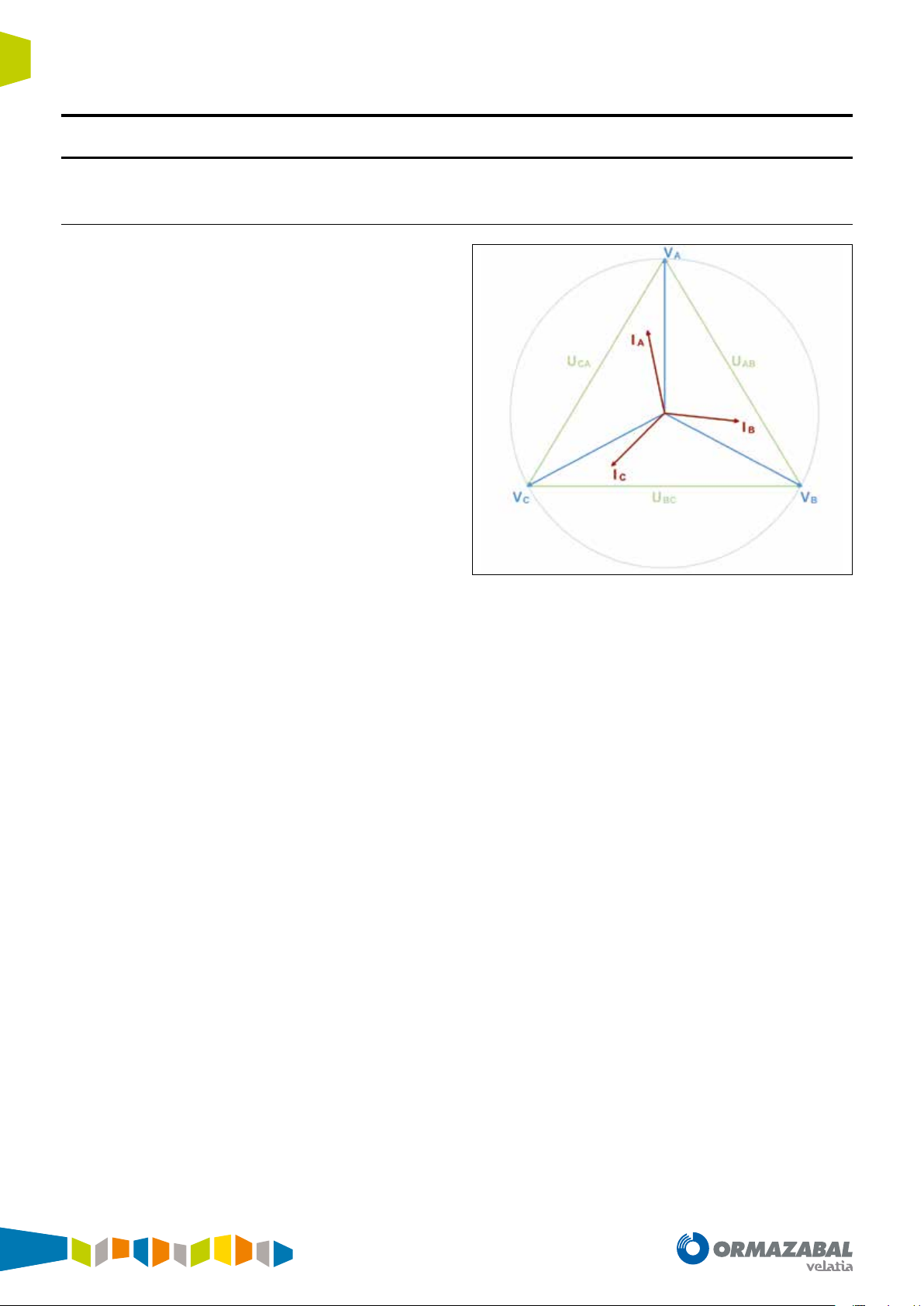
The current and voltage meterings are:
• Line currents I
• Line voltage: U
, IB and IC.
A
, UBC and UCA and Line voltages: VA, VB
AB
and VC.
• Residual currents and voltages. Represented as: I
N/INS
(3Io) and VN (3Vo).
Figure 3.1. Current and voltage metering
The final calibration is the overall calibration of sensors,
metering equipment, cabling and switchgear, and is
validated in an exhaustive test plan carried out in a
controlled environment which reproduces the reality of the
medium-voltage electrical distribution network.
All this process includes different scenarios:
• Maximum electromagnetic interference and temperature
rise scenarios of the assembly, carried out at rated
switchgear current.
• Maximum thermal variation scenarios, carried out in a
climate chamber between -10 °C and 60 °C.
• Scenarios with highly aggressive transient disturbance,
power and lightning impulse tests with medium-voltage
levels.
• etc.
These tests conclude in points such as: the ratio of the
number of turns of the current transformers, impedance
of the voltage reading inputs, etc. All this is tested and
validated on the final solution delivered to the customer.
18
IG-267-EN versión 01; 07/04/2017
General Instructions
ekor.rpa
3.2. Power meterings
Metering functions
The powers which are monitored (locally or remotely) are
1.28 second integrated meterings of the calculated RMS
instantaneous values.
Accredited meterings in precision class guarantee reliability
in the values obtained.
The equipment acts as a metering station for load analysis
or electrical supply quality monitoring tasks. The monitored
meterings for active and reactive power are single-phase
and three-phase, and three-phase only for apparent power.
3.3. Energy meter
The equipment is fitted with an "Active and reactive electrical
energy meter" which meets the particular requirements for
static energy meters. This is an indirect connection threephase meter which, along with the voltage and current
metering sensors, form a medium-voltage (MV) meter.
The energy meter accumulates 100 meterings of powers
P and Q integrated in a semicircle (1 second for 50Hz and
1.2 seconds for 60Hz). In total, there will be four meters:
three single-phase (A phase, B phase and C phase) and one
three-phase.
The meterings are made up of:
• Single-phase: Active PA, PB and PC and Reactive QA, QB
and QC.
• Three-phase: PT, QT and ST Powers and Power Factor
(P.F.).
Each meter has two active energy records (E+ and E-) and
four reactive energy records (Q1, Q2, Q3 and Q4), each of
them 32 bits. These registers have a bit to indicate overflow
and a reset option by command.
Active powers are expressed in kilovolts-hour (kWh) and
reactive powers are expressed in kilovolt amperes reactivehour (kVArh).
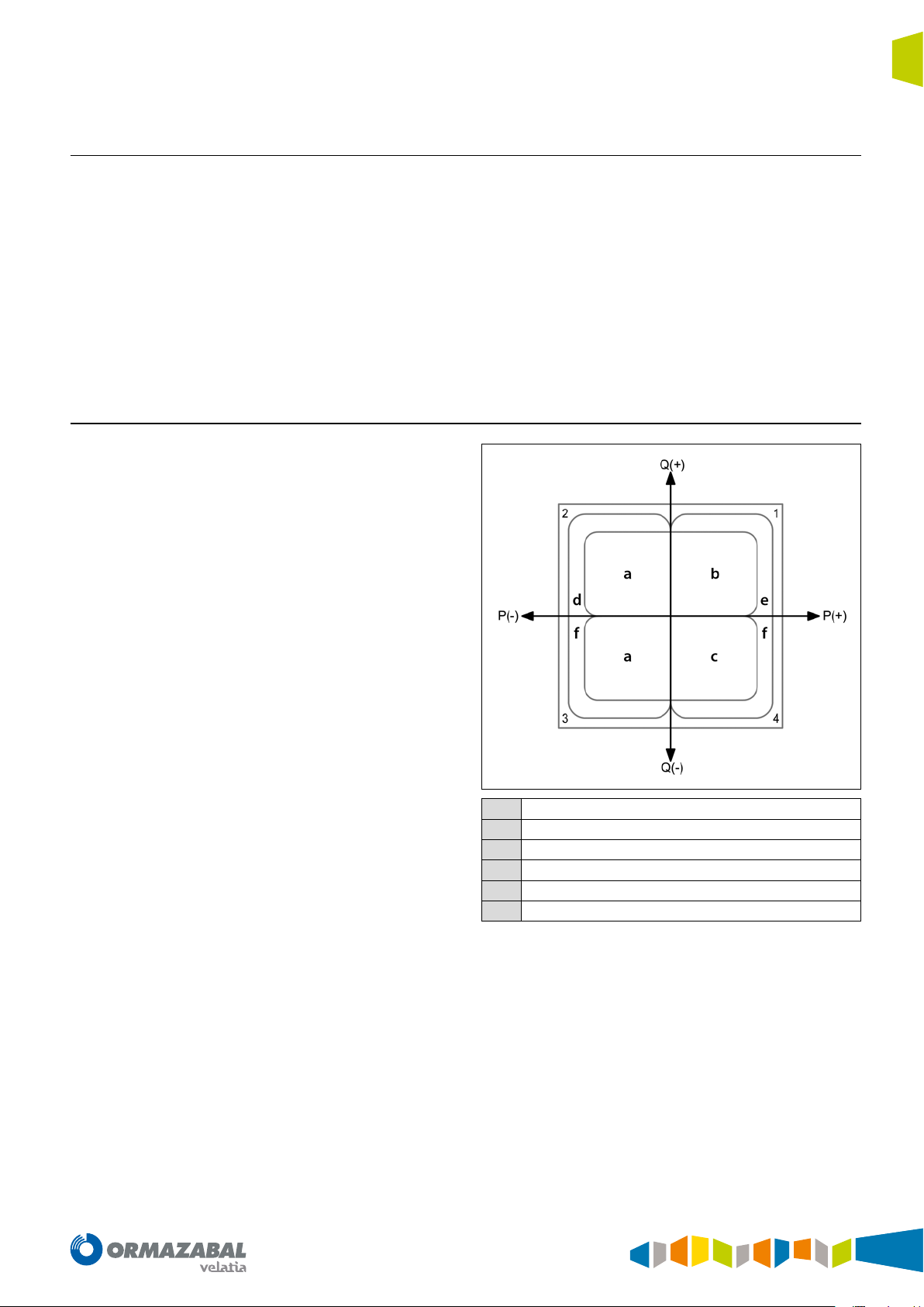
Reactive
a
Inductive
b
Capacitive
c
Generated
d
Consumed
e
Active
f
Active energy imported (in kWh): EA + , EB + , EC + and ET +
Active energy exported (kWh): EA - , EB - , EC - and ET Inductive reactive energy imported (kVArh): QA1, QB1, QC1 and QT1
Capacitive reactive energy imported (kVArh): QA2, QB2, QC2 and QT2
Inductive reactive energy exported (kVArh): QA3, QB3, QC3 and QT3
Capacitive reactive energy exported (kVArh): QA4, QB4, QC4 and QT4
Figure 3.2. Energies
IG-267-EN versión 01; 07/04/2017
19

Protection functions General Instructions
ekor.rpa
4. Protection functions
4.1. Overcurrent units
The ekor.rpa-100 systems are fitted with the following
overcurrent protection units:
Phases:
• Six phase overcurrent timed units (3 x 51.3 x 51(2)).
• Three phase overcurrent instantaneous units (3 x 50).
4.1.1. Timed overcurrent units
The phase, neutral and sensitive neutral timed units start
up if the fundamental value of the magnitude for each unit
exceeds the value 1.05 times the adjusted start-up, and are
reset when this value is below 0.95 times the adjusted value.
Tripping takes place if the unit is started up for the time set.
This time may be adjusted by selecting different types of
curve, in accordance with IEC and ANSI Standards.
The curves implemented in the ekor.rpa-100 units are:
IEC CURVES
• IEC DT: Defined time
• IEC NI: Normally inverse curve
• IEC VI: Very inverse curve
• IEC EI: Extremely inverse curve
• IEC LTI: Long time inverse curve
• IEC STI: Short time inverse curve
ANSI CURVES
• ANSI LI: Long time inverse curve
• ANSI NI: Normally inverse curve
• ANSI VI: Very inverse curve
• ANSI EI: Extremely inverse curve
These curves are detailed in the ANNEX section.
Neutral (Calculated):
• Two neutral timed overcurrent units (1 x 51N, 1 x 51(2)
N).
• A neutral instantaneous overcurrent unit (1 x 50N).
Sensitive neutral (measured):
• Two sensitive neutral timed overcurrent units (1 x 51NS,
1 x 51(2)NS).
• A sensitive neutral instantaneous overcurrent unit (1 x
50NS).
The settings for the timed units are:
• Enabling the unit: Enable/disable the unit (ON/OFF).
• Starting up the unit: Unit starting current. Variable
ranges in accordance with current transformers used.
• Time curve: Curve type (IEC DT, IEC NI, IEC VI, IEC EI, IEC
LTI, IEC STI, ANSI LI, ANSI NI, ANSI VI, ANSI EI).
• Time index: Time index, also known as time dial (from
0.05 to 1.60). This setting applies to all curve types
except for IEC DT.
• Fixed time: Unit tripping time (from 0.00 s to 100.00 s).
This setting only applies to IEC DT type curves.
• Torque control: Directional tripping mask (OFF,
FORWARD or REVERSE). To indicate the direction for
tripping:
- OFF: Regardless of the direction, the relevant
overcurrent unit will trip if the overcurrent conditions
are met.
- FORWARD: The corresponding overcurrent unit
will trip whenever the overcurrent conditions are
met, and the directional unit will give the FORWARD
signal.
- REVERSE: The corresponding overcurrent unit will
trip whenever the overcurrent conditions are met,
and the directional unit will give the REVERSE signal.
This setting will only be found in ekor.rpa-100 units
model 120.
20
IG-267-EN versión 01; 07/04/2017
General Instructions
ekor.rpa
4.1.2. Instantaneous overcurrent units
Protection functions
The phase, neutral and sensitive neutral instantaneous
units start up if the fundamental value of the magnitude for
each unit exceeds the value 1.00 times the adjusted startup, and are reset when this value is below 0.95 times the
adjusted value.
Tripping takes place if the unit is started up for the time set.
The settings for the instantaneous units are:
• Enabling the unit: Enable/disable the unit (ON/OFF).
• Starting up the unit: Unit starting current. Variable
ranges in accordance with current transformers used.
• Fixed time: Unit tripping time (from 0.00 s to 100.00 s).
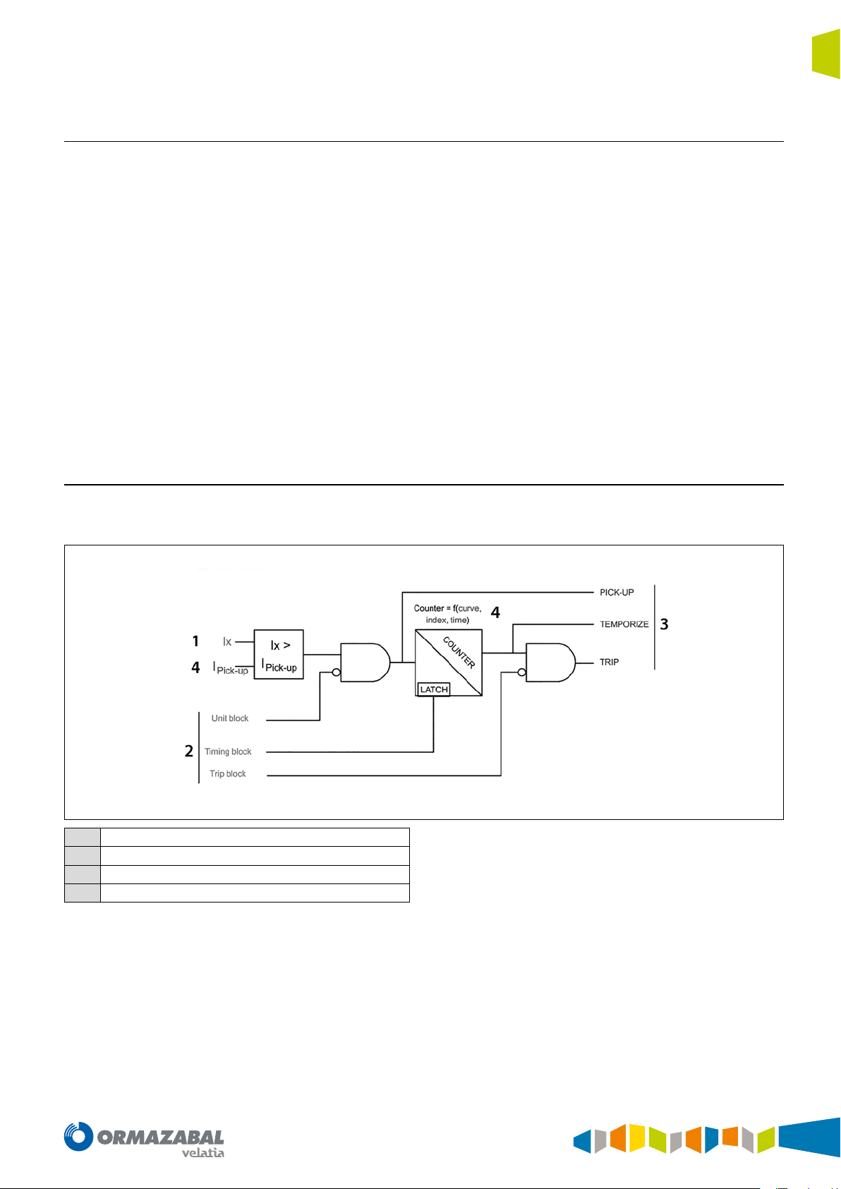
4.1.3. Block diagram
Any overvoltage unit complying with the diagram shown
below:
• Torque control: Directional tripping mask (OFF,
FORWARD or REVERSE). To indicate the direction for
tripping:
- OFF: Regardless of the direction, the relevant
overcurrent unit will trip if the overcurrent conditions
are met.
- FORWARD: The corresponding overcurrent unit
will trip whenever the overcurrent conditions are
met, and the directional unit will give the FORWARD
signal.
- REVERSE: The corresponding overcurrent unit will
trip whenever the overcurrent conditions are met,
and the directional unit will give the REVERSE signal.
This setting will only be found in ekor.rpa-100 units
model 120.
Metering
1
Input signal
2
Output signal
3
Settings
4
Figure 4.1. Block diagram
IG-267-EN versión 01; 07/04/2017
21
Protection functions General Instructions
ekor.rpa
Basically, the diagram shows that, whenever a magnitude
measured in real-time (Ix) exceeds the setpoint value (l
pick up
setting), a time counter counts down (counter: f (curve,
index, time), tripping when completely expired.
If the measured magnitude (Ix) drops below the setpoint
(I
) during timing, the unit and the meter are reset and
pick up
the unit remains idle.
All the units generate the following signalling:
• Pick-up: Activated when the measured magnitude (Ix)
exceeds a setpoint (I
setting) and disabled when the
pick up
metering value drops below the setpoint.
• Temporize: Activated when the time counter reaches
its end, and disabled when the metering value drops
below the setpoint.
• Trip: Activated when the temporize signal is activated,
and disabled when the metering value drops below the
setpoint.
4.2. Ultra-sensitive earth
This functionality is available in both directional and nondirectional ekor.rpa and corresponds to a particular case of
overcurrent detection for phase-to-earth faults. Primarily
used in networks with isolated neutral, resonant earthed
neutral or on highly resistive soils, where the phase-toearth fault current has a very low value.
Moreover, the overcurrent units can be blocked by the
maximum current blocking and second harmonic
blocking units detailed in the following sections.
Moreover, the overcurrent units can be blocked in three
different ways:
• Unit block: Blocks the unit, preventing start-up while
this input remains active.
• Timing Block: Freezes the time counter value while this
input is active.
• Trip Block: Allows the unit to advance, and blocks it
before the trip output.
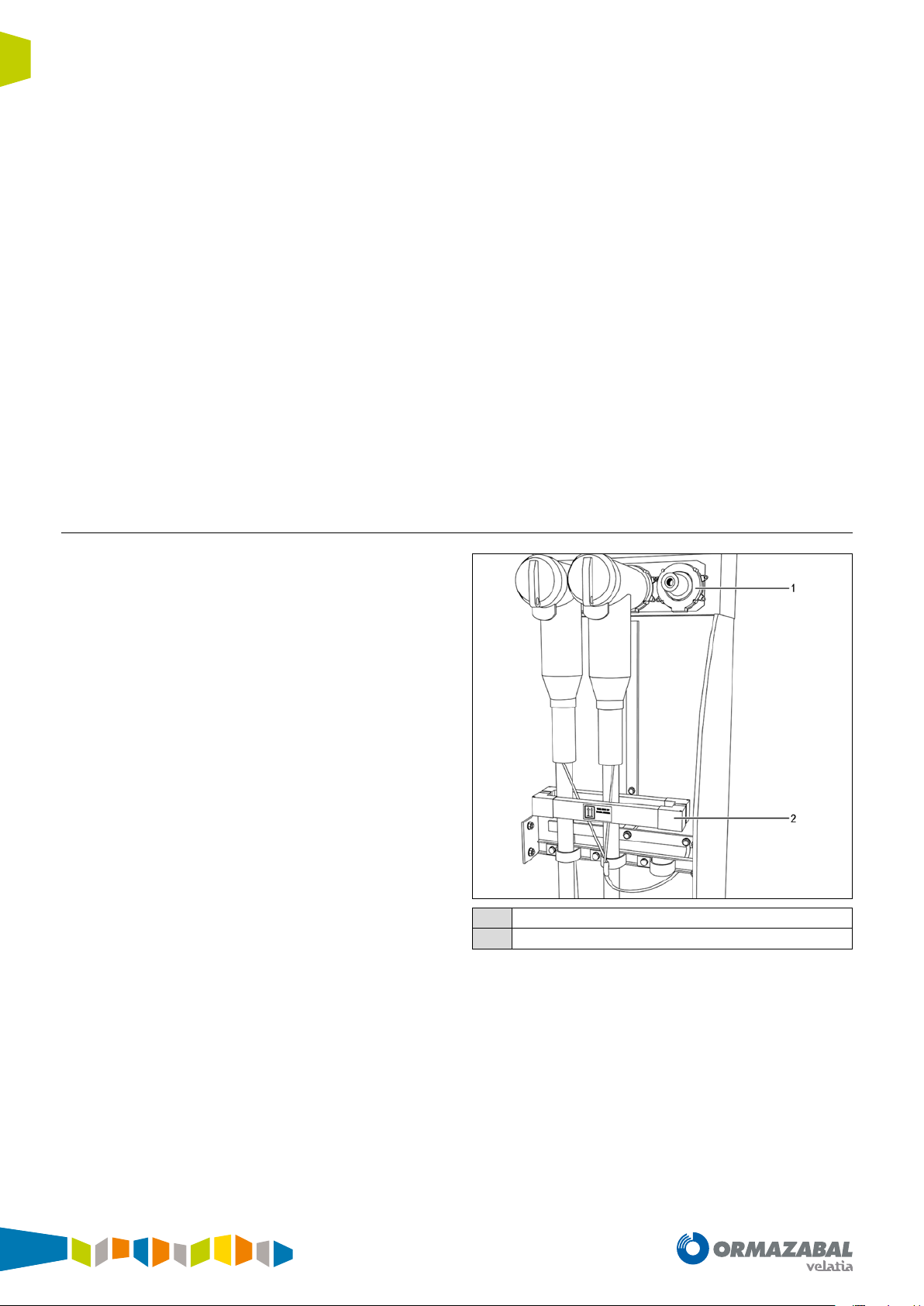
The current flowing to earth is detected using a toroidalcore current transformer which covers the three phases.
In this way, the metering is independent from the phase
current, thus avoiding errors in the phase metering sensors.
Using this type of toroidal-core means the measured
neutral currents due to unbalanced phases are reliable in
very low primary amp values. For this type of configuration,
the unit allows a minimum trip setting of 0.3 primary amps
in its Sensitive Neutral channel.
Voltage and current sensors
1
Zero-sequence transformers
2
Figure 4.2. Current sensors
22
IG-267-EN versión 01; 07/04/2017
General Instructions
ekor.rpa
4.3. Directional units
Protection functions
The directional units are combined with the overcurrent
units when taking a decision on tripping. In accordance with
the "torque control" direction setting (Forward or Reverse)
and the result of the direction of the fault, the overcurrent
units finish by tripping or not.
4.3.1. Phase directional units
Angular criterion
The phase directional units are units which, using the
angular criterion, determine the direction of each of the
3 phases. The polarisation voltage used for each phase is the
compound voltage corresponding to the other 2 phases.
These units determine direction based on:
• The calibrated settings.
• The phase difference existing between the polarisation
signal and the current signal.
The settings for the phase directional unit are:
The ekor.rpa-100 model 120 systems have the following
directional units:
• Three phase directional units (3 x 67)
• A neutral directional unit (1 x 67N)
• A sensitive neutral directional unit (1 x 67NS)
The Reverse direction zone will be the opposite of the
Forward zone. In other words, the above formula needs to
be turned around 180° in order to achieve the expression
which delimits the Reverse direction zone.
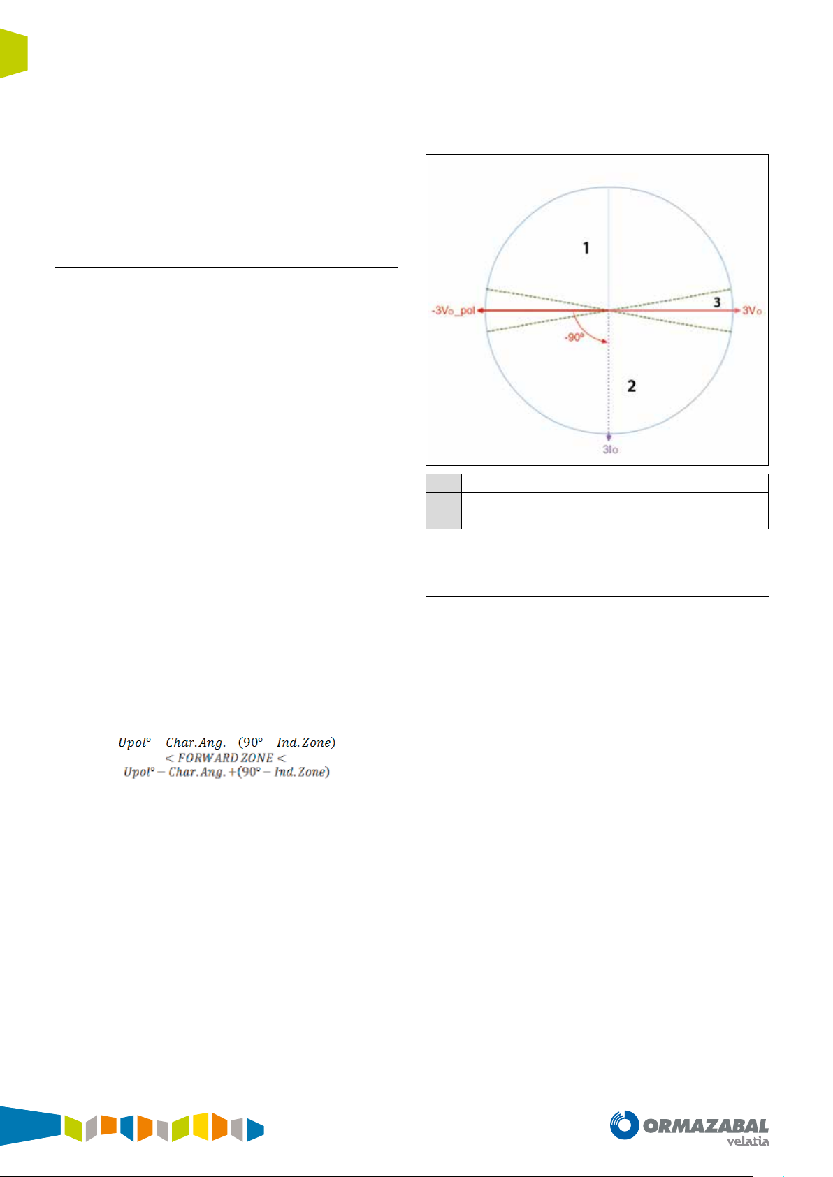
The directional units will indicate ndef direction if in the
indeterminate zone or polarisation voltage is below the
V
setting.
min
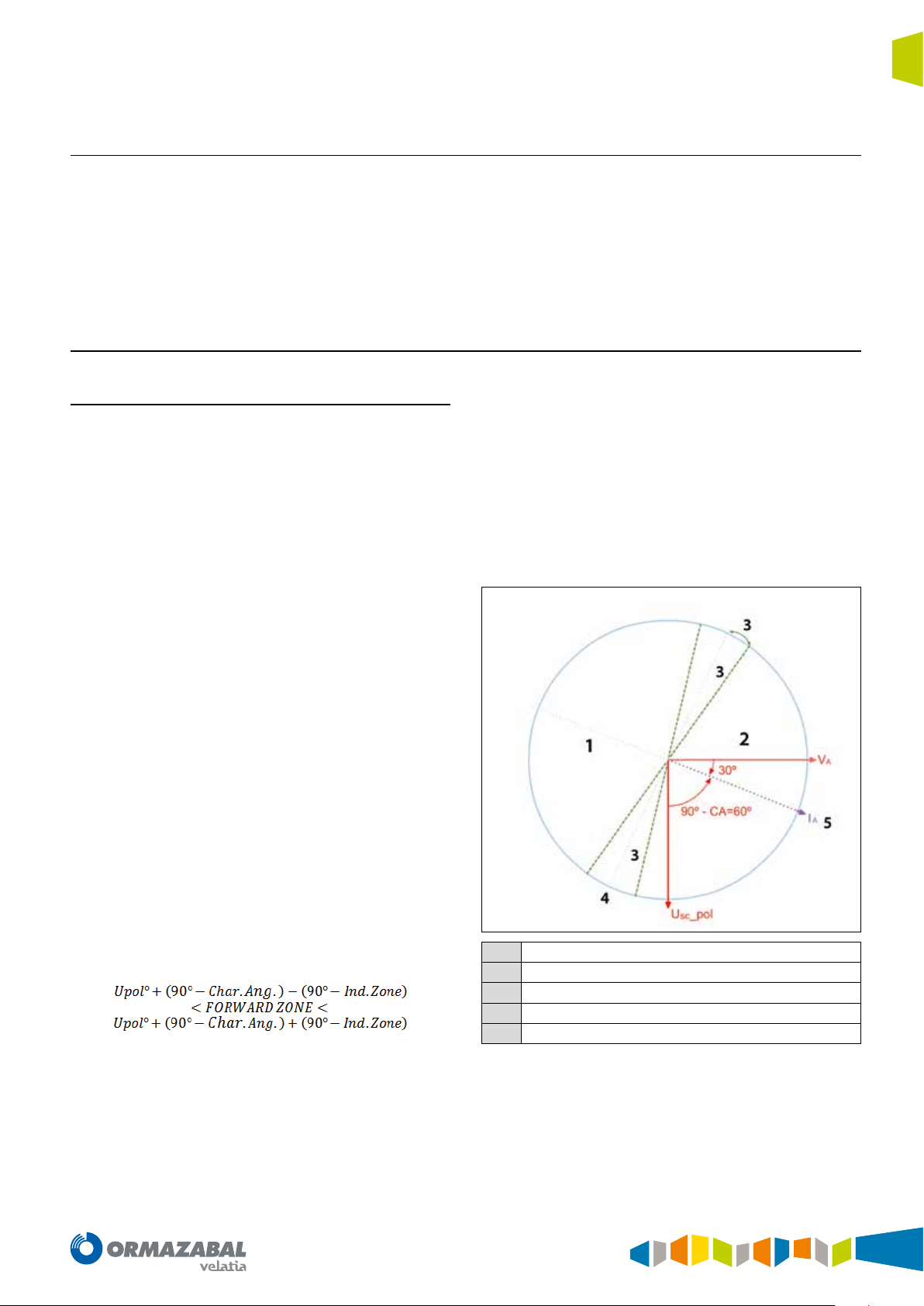
The figure shows an example of operation of the directional
unit of phase A:
• Characteristic phase angle: Characteristic angle
(from - 90.0° to 90.0°). This often corresponds to the
series impedance angle of the lines. Typical values in
distribution: 30° and 45°.
• Minimum phases voltage: Minimum polarisation
voltage (from 0.5 kV to 72.0 kV). Polarisation voltage
value as of which the directional unit considers the
angle reliable, and is capable of determining a direction.
• Indeterminate zone: Indeterminate zone angle (from
0.0° to 90.0°). Setting to establish the indetermination
zone which is close to the zero torque line.
The direction indicated by the units can be Forward, Reverse
or ndef (undefined).
The Forward direction zone is delimited by the following
formula:
Reserve
1
Forward
2
Indeterminate zone
3
Zero torque line
4
Maximum torque line
5
Figure 4.3. Phase A directional unit
IG-267-EN versión 01; 07/04/2017
23
Protection functions General Instructions
ekor.rpa
4.3.2. Neutral and sensitive neutral directional units
The neutral and sensitive neutral directional units include
two different criteria to determine direction: Directional
criterion and wattmetric criterion. The criterion is selected
through a setting in the unit itself.
Angular criterion
The angular criterion of the neutral and sensitive neutral
directional units is based on the phase difference between
the polarisation signal (-3V
(3Io).
The polarisation signal used is the 180° out-of-phase
residual voltage, i.e.- 3V
The settings for the neutral and sensitive neutral directional
unit, which apply to the angular criteria, are:
) and the residual current signal
o
.
o
• Characteristic neutral angle: Characteristic angle (from
- 90.0° to 90.0°). In distributions with earthed neutral,
this often corresponds to the earth impedance angle.
• Minimum neutral voltage: Minimum polarisation
voltage (from 0.5 kV to 72.0 kV). Polarisation voltage
value as of which the directional unit considers the
angle reliable, and is capable of determining a direction.
• Indeterminate zone: Indeterminate zone angle (from
0.0° to 90.0°). Setting to establish the indetermination
zone which is close to the zero torque line.
The direction indicated by the units can be Forward, Reverse
or ndef (undefined).
The Forward direction zone is delimited by the following
formula:
The Reverse direction zone will be the opposite of the
Forward zone. In other words, the above formula needs to
be turned around 180° in order to achieve the expression
which delimits the Reverse direction zone.
The directional units will indicate ndef direction if in the
indeterminate zone or polarisation voltage is below the V
min
setting.
The figure below shows an example of operation for the
neutral directional unit:
Reserve
1
Forward
2
Indeterminate zone
3
Figure 4.4. Neutral directional unit
Wattmetric criterion
The wattmetric criterion of the neutral and sensitive neutral
directional units is based on the phase difference between
the polarisation signal (- 3V
) and the residual current signal
o
(3lo), along with the magnitude of the residual active power.
The settings for the neutral and sensitive neutral directional
unit, which apply to the wattmetric criteria, are:
• Minimum neutral active power: Minimum residual
active power. Minimum residual active power value (in
absolute value), as of which direction other than ndef
(i.e. Forward or Reverse) can be considered. Variable
ranges in accordance with current transformers used.
• Minimum neutral voltage: Minimum polarisation
voltage (from 0.5 kV to 72.0 kV). Polarisation voltage
value as of which the directional unit considers the
angle reliable, and is capable of determining a direction.
• Indeterminate zone: Indeterminate zone angle (from
0.0° to 90.0°). Angle formed by the 90° axis and the line
which delimits the indeterminate zone.
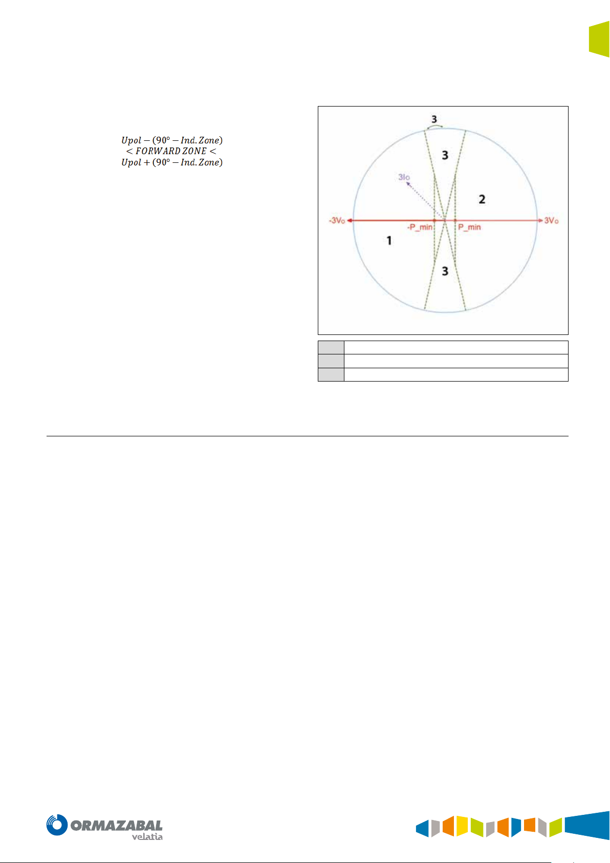
The direction indicated by the units can be Forward, Reverse
or ndef (undefined).
24
IG-267-EN versión 01; 07/04/2017
General Instructions
ekor.rpa
Protection functions
The unit will indicate Forward direction in the following
conditions:
• The residual current signal (3I
) drops in the following
o
zone:
The residual active power is lower than - P
min
.
The reverse direction zone will be the opposite of the
Forward zone. In other words, the above formula needs to
be turned around 180° in order to achieve the expression
which delimits the reverse direction zone. Furthermore,
residual active power must be greater than + P
min
.
The unit will give undefined direction if:
• The residual active power in absolute value is lower
than P
• The polarisation voltage value is lower than the V
min
.
min
setting.
• This is found in the indeterminate zone (see figure
below).
The figure below shows an example of operation for the
neutral directional unit with wattmetric criterion:
Reserve
1
Forward
2
Indeterminate zone
3
Figure 4.5. Neutral unit with wattmetric criterion
4.4. Thermal image unit
The ekor.rpa-100 model 120 systems are fitted with
the thermal image unit (49) for protection of lines and
transformers.
On certain occasions, the thermal overload of the element
to be protected cannot be detected by conventional
protection units. Furthermore, many of the elements
installed in the power system are being used ever-closer to
their thermal limits, making it necessary for the protection
devices used for these elements to have thermal units.
The thermal image unit is a unit which, in accordance with
the estimated thermal capacity value, generates alarm and
trip signals.
IG-267-EN versión 01; 07/04/2017
25
Protection functions General Instructions
ekor.rpa
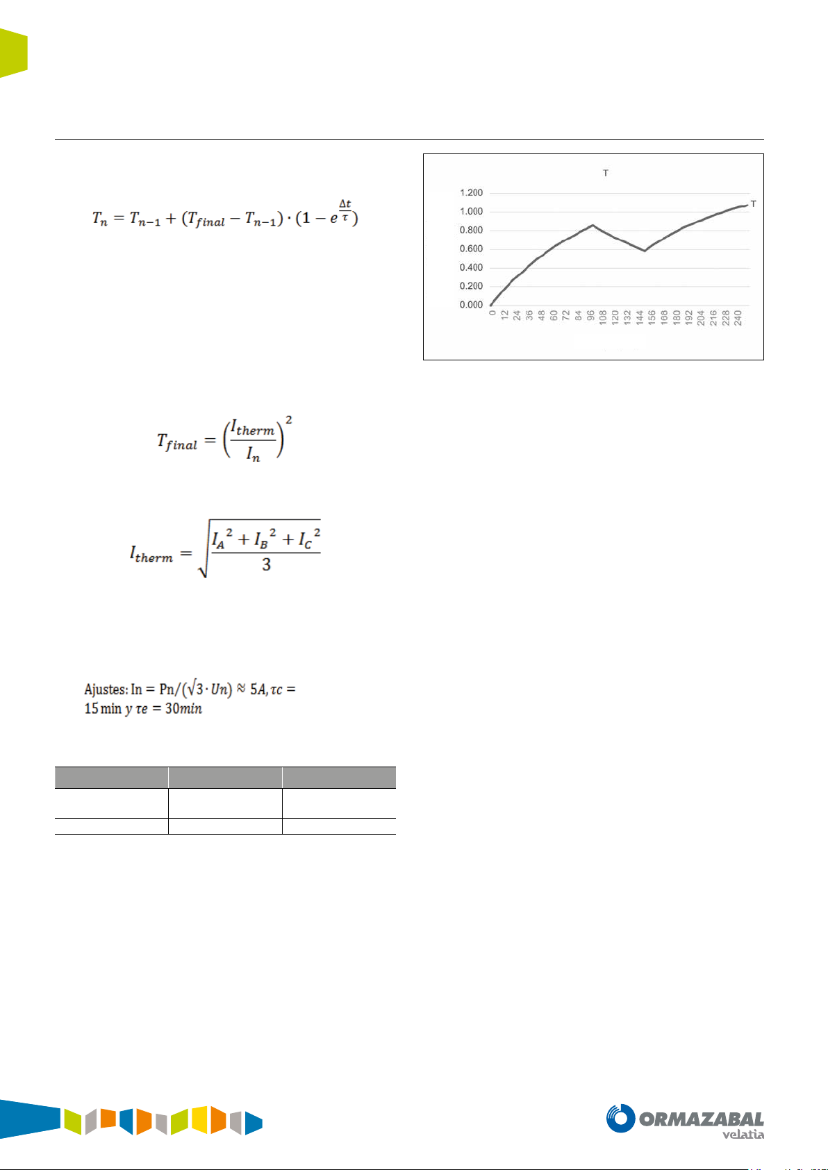
4.4.1. Estimated thermal capacity
The system estimates thermal capacity through the phase
currents (I
Where:
T
: Estimated thermal capacity at instant n
n
T
: Estimated thermal capacity at instant n-1
n-1
Δt: Time interval between consecutive n and n-1 instants
τ: Cooling or heating constant If T
constant will be applied in the formula If, on the other hand,
T
final
T
: Final thermal capacity This value is calculated based on the
final
, IB and IC), using the following formula:
A
< T
final
< T
, the cooling constant will be applied in the formula
n-1
, the temperature rise
n-1
adjusted rated current and the phase currents, in accordance
with the following formula:
capacity (T)
Estimated thermal
Time (min)
Figure 4.6. Estimated thermal capacity
Starting from an initial thermal capacity of 0 %, during the
first 100 min where current is 16 % higher than the rated
(5.8 A), estimated thermal capacity reaches a value of
84.6 %.
I
: The estimated mean thermal current based on the phase
therm
currents:
Example
The evolution of the thermal capacity estimated by the
system for a 250 kVA transformer in a 30 kV network
under the following conditions:
I
sequence read by the equipment:
therm
Interval 1 Interval 2 Interval 3
From 0 min
to 100 min
5.8 A 1.5 A 5.8 A
Table 4.1. I
read by the system
therm
From 100 min
to 150min
From 150 min
to 250min
In the next 50 min current drops to 30 % of rated current
(1.5 A), and this makes thermal capacity drop to 58.4 %.
A third interval identical to interval 1 has been chosen to
check the memory effect of the estimated thermal capacity.
In other words, a current which is 16 % higher than the rated
(5.8 A) for 100 min. It is observed that, after these 100 min,
thermal capacity reaches 106.3 %, thus exceeding 100 %
(typical trip level setting).
This difference in the estimated thermal capacity between
intervals 1 and 3 is due to the fact that previous statuses
are taken into account in the calculation. Hence, as the first
interval starts from a thermal capacity equal to 0 %, the third
interval starts from the thermal capacity accumulated up
to this moment, taking into account all the thermal stress
suffered by the element to be protected. This means the
estimated thermal capacities are different in these intervals.
26
IG-267-EN versión 01; 07/04/2017
General Instructions
ekor.rpa
4.4.2. Functionality
Protection functions
The thermal image unit starts up (with an alarm signal) if the
thermal capacity value exceeds the alarm level setting (%),
tripping whenever the trip level setting is exceeded (%).
Once the unit has tripped, this will reset when the thermal
capacity value drops below the trip reset level setting (%).
The settings for the thermal image unit are:
• Enabling the unit: Enable/disable the unit (ON/OFF).
• Temperature rise constant: Temperature rise constant
(from 3 min to 60 min).
• Cooling constant: Cooling constant (from 3 min to
180 min).
• Alarm level: Alarm threshold percentage. The thermal
capacity percentage from which an alarm situation is
considered (from 80 % to 100 %).
• Trip level: Trip threshold percentage. The thermal
capacity percentage from which a thermal overload is
tripped (from 100 % to 200 %).
• Trip reset level: Reset threshold. The thermal capacity
percentage below which the unit is reset (from 50 % to
99 %).
• Rated current: Rated current of the element to be
protected. Variable ranges in accordance with current
transformers used.
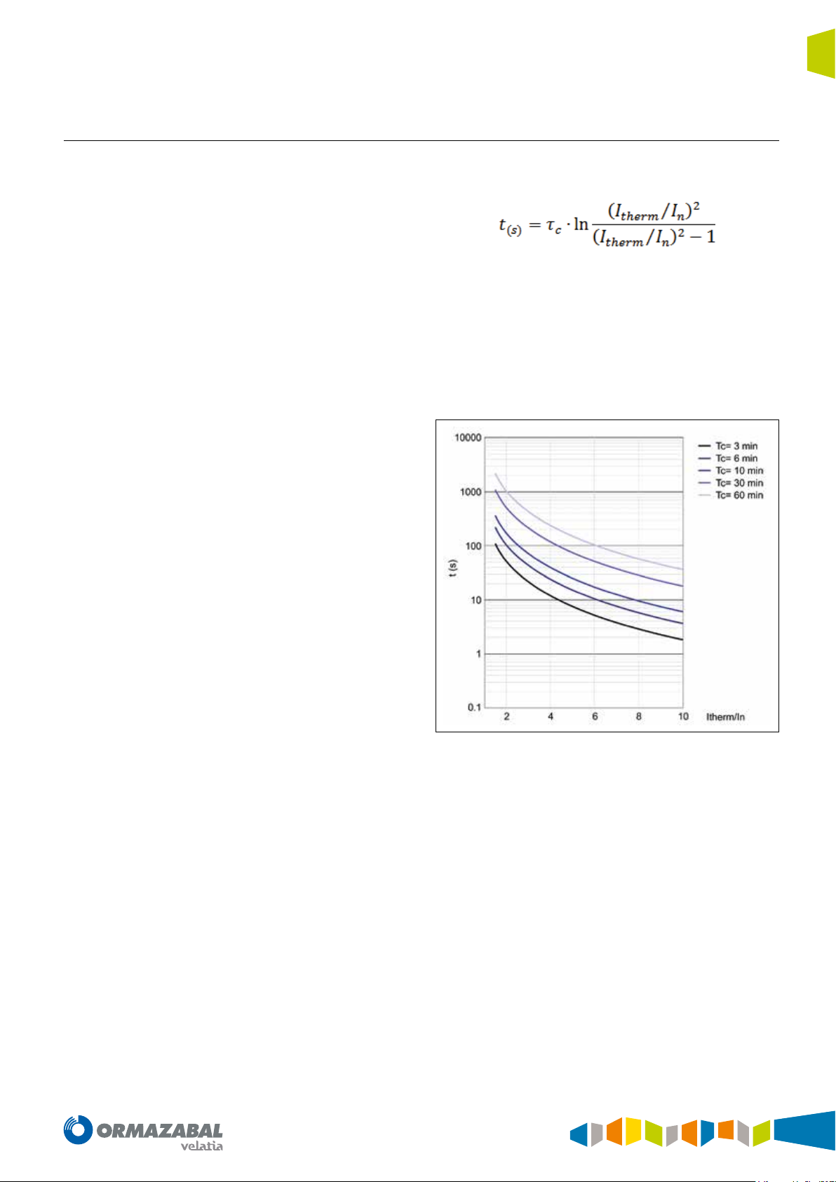
The time taken to reach tripping, based on a thermal
capacity equal to zero, given by the following formula:
Where:
t: Tripping time
τ
: Temperature rise constant
c
I
: Adjusted rated current
n
I
: The estimated mean thermal current based on the phase
therm
currents
The trip times for different temperature rise constants are
shown graphically below:
Figure 4.7. Trip time
IG-267-EN versión 01; 07/04/2017
27
Protection functions General Instructions
ekor.rpa
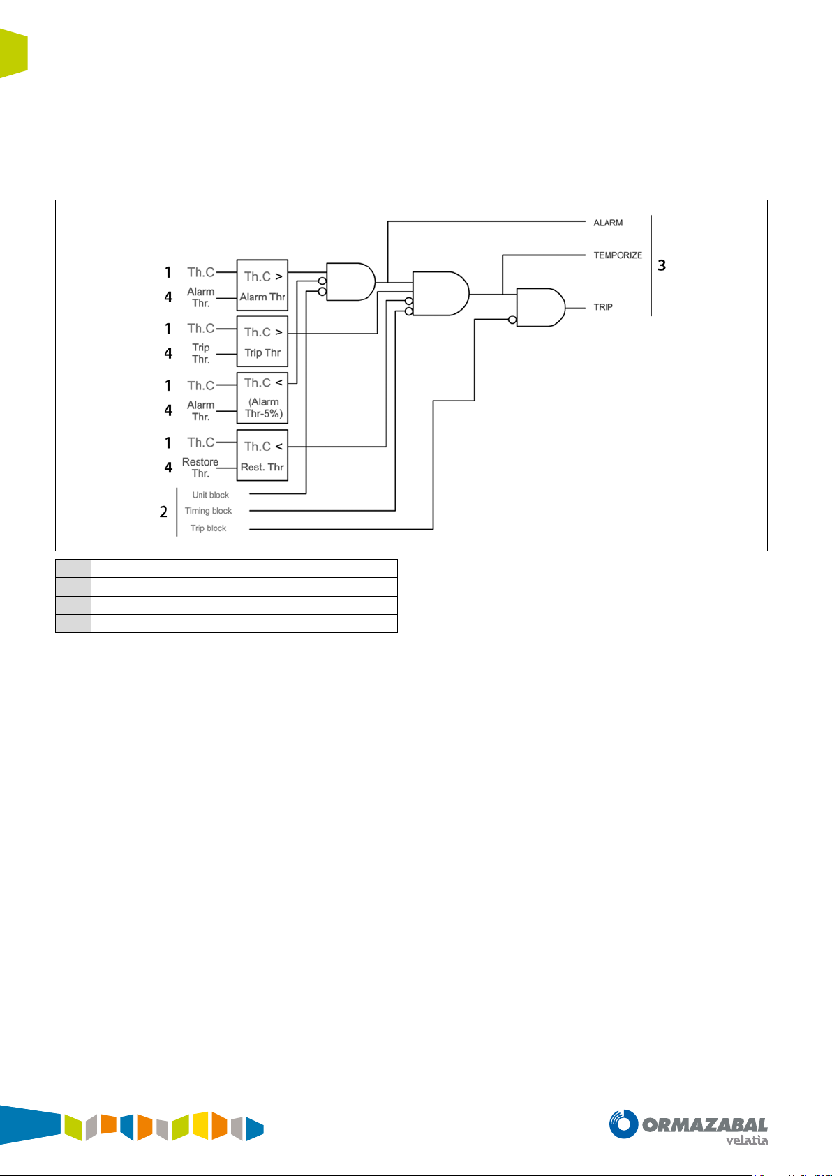
4.4.3. Block diagram
The thermal image unit complies with the following block
diagram :
Metering
1
Input signal
2
Output signal
3
Settings
4
Figure 4.8. Block diagram
The thermal image unit generates the following signal:
• Alarm: Activated when the estimated magnitude of
thermal capacity (Th. C) exceeds the “Alarm Threshold”
setting, and is disabled when estimated thermal capacity
(Th. C) drops below the “Alarm Threshold – 5%” setting.
• Temporize: Activated when the estimated magnitude
of thermal capacity (Th. C) exceeds the “Trip Threshold”
setting, and is disabled when estimated thermal capacity
(Th. C) drops below the “Restore Threshold” setting.
• Trip: Activated when the temporize signal is activated,
and disabled when the estimated thermal capacity (Th.
C) drops below the “Restore Threshold” setting.
Moreover, the thermal image unit can be blocked by the
maximum current blocking unit detailed in the following
sections.
The thermal image unit can be blocked in three different
ways:
• Unit Block: Blocks the unit, preventing start-up while
this input remains active.
• Timing Block: Blocks the unit, allowing it to run the
alarm signal but not allowing the temporize or trip signal.
• Trip Block: Allows the unit to advance, and blocks it
before the trip output.
28
IG-267-EN versión 01; 07/04/2017
General Instructions
ekor.rpa
4.5. Broken conductor unit
Protection functions
The ekor.rpa-100 model 120 systems are fitted with the
broken conductor unit (46BC).
Conventional protection functions cannot detect conditions
in which one of the conductors is broken.
4.5.1. Calculation of sequence currents
The broken conductor unit is supplied by the sequence
currents (I
, I2 and Io) previously calculated by the system.
1
The sequence current calculation is carried out in
accordance with these formulae:
The broken conductor unit (46 Broken Conductor) can
be used to detect broken conductors, by monitoring
the sequence currents, and another series of conditions
detailed in this section.
Where,
With the phase A sequence components known, the B
and C sequence components will be identical in modules,
displaced 120° in angle in the case of direct and inverse
sequence, and with the same angle in the case of zerosequence.
IG-267-EN versión 01; 07/04/2017
29
Protection functions General Instructions
ekor.rpa
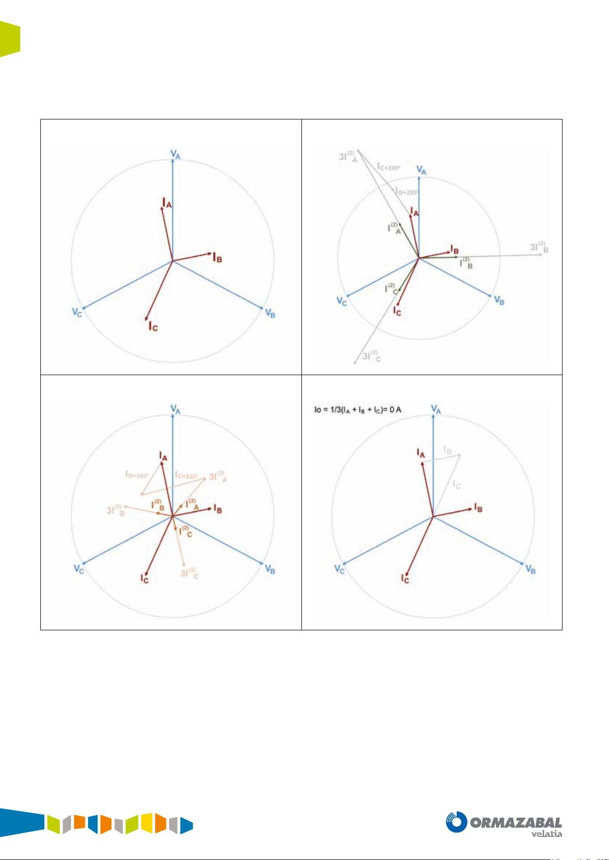
The following image shows an example of calculation of the
sequences based on an imbalanced system. It is observed
that the system has a large inverse component, but no zero-
Line currents Direct-sequence currents
sequence (situation which can come about in lines which
are not uniformly charged in the three phases):
Inverse-sequence currents Zero-sequence currents
Figure 4.9. Calculation of sequences
30
IG-267-EN versión 01; 07/04/2017

General Instructions
ekor.rpa
Protection functions
Another example which applies for the case of broken
conductors could be as follows: One of the phases with
no current (without the capacitive currents which can go
Line currents Direct-sequence currents
through the broken conductor) and the other two counterdirection phases:
Inverse-sequence currents Zero-sequence currents
Figure 4.10. Calculation of sequences
IG-267-EN versión 01; 07/04/2017
31

Protection functions General Instructions
ekor.rpa
4.5.2. Functionality
The broken conductor unit starts up when a series of
conditions are met, as detailed below, and is reset when any
of these conditions drops to 0. Tripping takes place if the
unit is started up for the time set.
The settings for the broken conductor unit are:
• Enabling the unit: Enable/disable the unit (ON/OFF).
• Base current: The magnitude to be used to calculate the
ratios. Can be I1 (direct sequence) or I
(primary rated
n
current of the current transformer). The In value will vary
in accordance with the current transformers used.
• Starting up the unit: Start-up value of I2 (inverse
sequence)/Ib (base current) (from 0.05 to 0.5 p.u.).
4.5.3. Block diagram
The broken conductor unit complies with the following
block diagram:
• Unit timing: Unit tripping time (from 0.05 s to 600.00 s).
• Minimum current threshold for phases: Phase current
value, below which it is considered that the line is open.
Although the line is actually open, there may be current
flowing through this phase (through capacitive elements
of the lines, as this line continues to supply some stations
located before the broken conductor). Variable ranges in
accordance with current transformers used.
• Maximum current threshold for neutral: Maximum
ratio of Io (zero-sequence)/Ib (base current ) as of which
it is considered a single-phase fault rather than an
broken conductor (from 0.00 to 0.5 p.u.). If the setting
is 0.00, the 46BC unit does not make any zero-sequence
current check.
Input signal
1
Output signal
2
Settings
3
Figure 4.11. Block diagram
32
IG-267-EN versión 01; 07/04/2017

General Instructions
ekor.rpa
The four conditions which make the broken conductor unit
start up are:
Protection functions
Figure 4.12. Conditions A, B, C and D
The broken conductor unit generates the following signal:
• Pick up: Activated when the four conditions come
about at the same time, and disabled when any of the 4
conditions are no longer met.
• Temporize: Activated when the Pick up signal remains
active for the time set, and disabled when any of the
4 conditions are no longer met..
• Trip: Activated when the Temporize signal is activated, and
disabled when any of the 4 conditions are no longer met.
4.6. Voltage units
The ekor.rpa-100 model 120 systems are fitted with the
following voltage protection units:
Phases:
1. Three phase overvoltage timed units (3 x 59_TEMP)
2. Three phase overvoltage instantaneous units
(3 x 59_INST)
3. Three phase undervoltage timed units
(3 x 27_TEMP)
4. Three phase undervoltage instantaneous units
(3 x 27_INST)
Moreover, the broken conductor unit can be blocked by the
maximum current blocking unit detailed in the following
sections.
The broken conductor unit can be blocked in three
different ways:
• Unit Block: Blocks the unit, preventing start-up while
this input remains active.
• Timing Block: Freezes the time counter value while this
input is active.
• Trip Block: Allows the unit to advance, and blocks it
before the trip output.
Neutral (calculated):
1. A neutral overvoltage timed unit (1 x 59N_TEMP)
2. A neutral overvoltage instantaneous unit
(1 x 59N_INST)
IG-267-EN versión 01; 07/04/2017
33

Protection functions General Instructions
ekor.rpa
4.6.1. Timed overvoltage units
The phase and neutral timed units start up if the
fundamental value of the magnitude (single or compound
voltage, which can be set by the user) for each unit is below
the value 1.05 times the adjusted start-up, and are reset
when this value exceeds 0.95 times the adjusted value.
Tripping takes place if the unit is started up for the time
set. This time may be adjusted by selecting different types
of curve, in accordance with IEC and ANSI Standards. The
curves implemented for the voltage units are identical to
those in the overcurrent units.
4.6.2. Instantaneous overvoltage units
The phase and neutral timed units start up if the
fundamental value of the magnitude for each unit exceeds
the value 1.00 times the adjusted start-up, and are reset
when this value is below 0.95 times the adjusted value.
Tripping takes place if the unit is started up for the time set.
The settings for the timed units are:
• Enabling the unit: Enable/disable the unit (ON/OFF).
• Working voltage: Selection of the magnitude for
working: Single or compound voltage (Phase to neutral
or Phase to phase).
• Starting up the unit: Unit starting voltage (from 0.5 kV
to 72.0 kV).
• Time curve: Curve type (IEC DT, IEC NI, IEC VI, IEC EI, IEC
LTI, IEC STI, ANSI LI, ANSI NI, ANSI VI, ANSI EI).
• Inverse curve time index: Time index, also known as
time dial (from 0.05 to 1.60). This setting applies to all
curve types except for IEC DT.
• Fixed time: Unit tripping time (from 0.00 s to 100.00 s).
This setting only applies to IEC DT type curves.
The settings for the instantaneous units are:
• Enabling the unit: Enable/disable the unit (ON/OFF).
• Working voltage: Selection of the magnitude for
working: Single or compound voltage (Phase to Phase or
Phase to Neutral).
• Starting up the unit: Unit starting voltage (from 0.5 kV
to 72.0 kV).
• Fixed time: Unit tripping time (from 0.00 s to 100.00 s).
34
IG-267-EN versión 01; 07/04/2017

General Instructions
ekor.rpa
4.6.3. Timed undervoltage units
Protection functions
The phase timed units start up if the fundamental value of
the magnitude (single or compound voltage, which can be
set by the user) for each unit is below the value 0.95 times
the adjusted start-up, and are reset when this value exceeds
1.05 times the adjusted value.
Tripping takes place if the unit is started up for the time
set. This time may be adjusted by selecting different types
of curve, in accordance with IEC and ANSI Standards. The
curves implemented for the voltage units are identical to
those in the overcurrent units.
4.6.4. Instantaneous undervoltage units
The phase instantaneous units start up if the fundamental
value of the magnitude (single or compound voltage, which
can be set by the user) for each unit is below the value 1.00
times the adjusted start-up, and are reset when this value
exceeds 1.05 times the adjusted value
Tripping takes place if the unit is started up for the time set.
The settings for the timed units are:
• Enabling the unit: Enable/disable the unit (ON/OFF).
• Working voltage: Selection of the magnitude for
working: Single or compound voltage (Phase to neutral
or Phase to phase).
• Starting up the unit: Unit starting voltage (from 0.5 kV
to 72.0 kV).
• Time curve: Curve type (IEC DT, IEC NI, IEC VI, IEC EI,
IEC LTI, IEC STI, ANSI LI, ANSI NI, ANSI VI, ANSI EI).
• Inverse curve time index: Time index, also known as
time dial (from 0.05 to 1.60). This setting applies to all
curve types except for IEC DT.
• Fixed time: Unit tripping time (from 0.00 s to 100.00 s).
This setting only applies to IEC DT type curves.
The settings for the instantaneous units are:
• Enabling the unit: Enable/disable the unit (ON/OFF).
• Working voltage: Selection of the magnitude for
working: Single or compound voltage (Phase to Phase or
Phase to Neutral).
• Starting up the unit: Unit starting voltage (from 0.5 kV
to 72.0 kV).
• Fixed time: Unit tripping time (from 0.00 s to 100.00 s).
IG-267-EN versión 01; 07/04/2017
35

Protection functions General Instructions
ekor.rpa
4.6.5. Block diagram
Any voltage unit complying with the diagram shown below.
Metering
1
Input signal
2
Output signal
3
Settings
4
Figure 4.13. Block diagram
The diagram represents, whenever the magnitude measured
in real time (Vx) is: a) higher in the case of overvoltage units:
59 or, b) lower in the case of undervoltage units: 27 than the
setpoint value (V
setting), a time counter counts down
pick up
(counter: ƒ (curve, index, time) tripping once completely
expired.
If the measured magnitude (Vx) drops (overvoltage units: 59)
or increases (undervoltage units: 27) over setpoint (V
pick up
),
the unit and the counter are reset, with the unit remaining idle
All the units generate the following signalling:
• Pick-up: Activated when the measured magnitude (Vx)
is higher (overvoltage units: 59) or below (undervoltage
units: 27) a setpoint (V
setting), and disabled when
pick up
the metering value is lower (overvoltage units: 59) or
higher (undervoltage units: 27) than the setpoint.
• Temporize: Activated when the time counter reaches
its end, and disabled when the metering value is lower
(overvoltage units: 59) or higher (undervoltage units: 27)
than the setpoint.
• Trip: Activated when the Temporize signal is activated,
and disabled when the metering value is lower
(overvoltage units: 59) or higher (undervoltage units: 27)
than the setpoint.
Moreover, the voltage units can be blocked by the
maximum current blocking unit detailed in the following
sections.
Moreover, the voltage units can be blocked in three different
ways:
• Unit Block: Blocks the unit, preventing start-up while
this input remains active.
• Timing Block: Freezes the time counter value while this
input is active.
• Trip Block: Allows the unit to advance, and blocks it
before the trip output.
36
IG-267-EN versión 01; 07/04/2017

General Instructions
ekor.rpa
4.7. Second harmonic blocking unit
Protection functions
The ekor.rpa-100 systems are fitted with the second
harmonic blocking unit.
This function blocks the overcurrent units whenever the
transformer energisation conditions are met:
4.7.1. Functionality
The second harmonic blocking unit has 5 modules, one
for each current (I
, IB, IC, IN and INS). Each of these modules
A
generates a blocking signal associated to the overcurrent
unit whenever the following conditions are met
simultaneously:
• The ratio between the second harmonic and the
corresponding current fundamental must be higher
than the setting “2nd harmonic threshold ratio”.
• The fundamental value of the corresponding current
must be higher than the setting “Min. phase/neutral/
senst. neutral current”.
Moreover, the following condition must be met in the three
phase current modules (I
, IB and IC):
A
• The fundamental value of the corresponding current
must be lower than the setting “Max phase current”.
• High fundamental current value.
• High second harmonic current value.
Any of the following conditions must come about to disable
the block:
• The ratio between the second harmonic and the
corresponding current fundamental must be lower than
the setting “Second harmonic threshold”.
• The fundamental value of the corresponding current
must be lower than the setting “Min. phase/neutral/
senst. neutral current”.
• The time during which it remains blocked must be lower
than the setting “Max. blocking time”.
• The fundamental value of the corresponding current
must be higher than the setting “Max phase current”
(modules for I
, IB and IC only).
A
IG-267-EN versión 01; 07/04/2017
37

Protection functions General Instructions
ekor.rpa
The settings for the second harmonic blocking unit are:
• Enabling the unit: Enable/disable the unit (ON/OFF).
• Second harmonic threshold: Second harmonic current
threshold (as a percentage relative to the fundamental
current) as of which the second harmonic condition is
met (from 5.0 % to 100.0 %).
• Cross-blocking: Setting to select how blocking a phase
(A, B or C) affects the other phases (also known as crossblocking). Possible settings:
- OFF: Indicates that there is no cross-blocking. In
other words, the second harmonic blocking signal
is only activated in those phases which meet the
conditions.
- 1 OUT OF 3: Indicates that there is cross-blocking.
In other words, blocking conditions simply need to
exist in any of the three phases in order to activate
the second harmonic blocking signal in all phases
(A, B and C).
- 2 OUT OF 3: As in the previous case, although this
time the blocking conditions must be found in at
least 2 of the 3 phases in order to activate the second
harmonic blocking signal in all phases (A, B and C).
• Minimum current threshold for phases: Fundamental
phase current as of which the condition corresponding
to minimum fundamental current is met. Variable ranges
in accordance with the current transformers used.
• Minimum current threshold for neutral: Fundamental
neutral current as of which the condition corresponding
to minimum fundamental current is met. Variable ranges
in accordance with the current transformers used.
• Minimum current threshold for sensitive neutral:
Fundamental sensitive neutral current as of which the
condition corresponding to minimum fundamental
current is met. Variable ranges in accordance with the
current transformers used.
• Maximum current threshold for phases: Fundamental
phase current below which the condition corresponding
to maximum fundamental phase current is met. Variable
ranges in accordance with the current transformers
used.
• Maximum block time: Maximum time blocking will
remain active (from 0.01 s to 5.00 s). If the block persists
after this time, the unit will be reset, releasing the
overcurrent units.
• Overcurrent units blocking mode: Mode in which the
corresponding overcurrent unit can be blocked (OFF,
UNIT, TIMING or TRIP).
38
IG-267-EN versión 01; 07/04/2017

General Instructions
ekor.rpa
4.7.2. Block diagram
The second harmonic blocking unit complies with the
following block diagram:
Protection functions
Figure 4.14. Block diagram
IG-267-EN versión 01; 07/04/2017
39

Protection functions General Instructions
ekor.rpa
The second harmonic blocking unit generates the following
signal:
• UHARM_IA_BLOCK: Signal which indicates whether
phase A complies with the conditions necessary for
second harmonic blocking or not.
• UHARM_IB_BLOCK: Signal which indicates whether
phase B complies with the conditions necessary for
second harmonic blocking or not.
• UHARM_IC_BLOCK: Signal which indicates whether
phase C complies with the conditions necessary for
second harmonic blocking or not.
• UHARM_IN_BLOCK: Signal which indicates whether
the calculated neutral complies with the conditions for
second harmonic blocking or not.
• UHARM_INS_BLOCK: Signal which indicates whether
the sensitive neutral complies with the conditions
necessary for second harmonic blocking or not.
The diagram below shows how to wire the second harmonic
blocking signals to the overcurrent units:
Figure 4.15. Cabling by second harmonic
The blocking input signals of the overcurrent units are the
result of the logic carried out between the “U2HARM_IX_
BLOCK” blocking signal generated by the second harmonic
blocking unit and the “Blocking mode” setting of the
corresponding overcurrent unit. In consequence, whenever
blocking conditions exist, the corresponding overcurrent
unit is blocked in the way indicated by the “Blocking mode”
setting of the associated unit.
The possible blocking modes are:
• OFF: The unit is not blocked even when the conditions
necessary for blocking come about.
• UNIT: Blocks the unit, preventing start-up whenever the
conditions necessary for blocking come about.
• TIMING: Freezes the time counter value whenever the
conditions necessary for blocking come about.
• TRIP: Allows the unit to advance and blocks it before
the trip output, whenever the conditions necessary for
blocking come about.
40
IG-267-EN versión 01; 07/04/2017

General Instructions
ekor.rpa
Protection functions
4.8. Block by I
max
The maximum current blocking unit is implemented in
the ekor.rpa-100 systems, p type, used in fuse protection
cubicles, allowing the protection units to be blocked when
the line current exceeds certain set values.
Below the current set in the maximum current blocking
unit, the element in charge of protection will be the
ekor.rpa-100 unit. On the other hand, the unit will be
blocked if the current exceeds this value, in which case the
fuses will be entrusted with protection.
If the current in any of the 3 phases is above the value set
in the maximum current blocking unit, all protection units
will be blocked until current drops below the set value.
The settings for this unit are not accessible by the user and
will be set by the manufacturer in accordance with the
characteristics of the cubicle where the ekor.rpa-100 unit
is to be installed.
Relay protection
1
Fuse protection
2
Figure 4.16. Block by I
max
IG-267-EN versión 01; 07/04/2017
41

Detection, automation and control functions General Instructions
ekor.rpa
5. Detection, automation and control functions
5.1. Recloser automation
5.1.1. Functionality
The recloser automation is implemented in the
ekor.rpa-100 systems used in protection cubicles with
circuit-breaker. This allows automatic line reclosing, once
one of the overcurrent units has ordered tripping and the
switch has opened.
This function is primarily used in overhead lines, where a
great number of faults are usually transient: electrical arcs
due to the proximity of two conductors caused by the wind,
tree falling on lines, etc. Transient faults can be cleared by
momentarily de-energising the line. Once enough time has
elapsed to deionise the air, there is a very high probability
that the fault will not re-occur when power is re-established.
The recloser function implemented in the ekor.rpa-100
systems is of three-core type, with simultaneous reclosing
for the three phases. The recloser can carry out up to four
reclosing attempts, and it is possible to define a different
reclosing time for each of them. Furthermore, there are
independent recloser time settings for earth faults or
between phases.
5.1.2. VREF
The recloser cycle starts when any of the overcurrent units
trip whilst the recloser is in automatic and unblocked. Under
these conditions, the relay waits for the first reclosing time
and sends a command signal for the switch to close.
When the switch closes, the block timing starts counting. As
with the recloser times, there are 2 independent blocking
times: that associated to earth faults, and that associated
to faults between phases. The reclosing is considered
successful if, once the block timing has elapsed, the fault
disappears after the switch closes. Any trip that occurs
afterwards is considered to be caused by a new fault and
the first reclosing timing restarts.
If, after the first closing, a new trip occurs before blocking
time has elapsed, it is considered to be caused by the same
fault, meaning the function will start the timing of the
second reclosing.
The logic explained in the above paragraph will continue
to be applied until the number of configured reclosings is
exhausted. This means that the fault is permanent and it will
change to the final trip condition.
There is the option of controlling reclosing by way of a
status programmable in the user PLC (ESP_VREF). Whenever
this function is used, this status must be active after tripping
in order to allow reclosing. Whenever it is active, it will
continue with the recloser cycle as described above. On the
other hand, the automation will wait for a time equal to the
Tvref setting if the aforementioned status is disabled after
tripping, and will definitively trip if it is not enabled over the
course of this time.
42
This functionality can be useful when monitoring voltage
in busbars. Reclosings can be made conditional on the
presence of voltage in busbars by associating voltage in
busbars to the programmable status.
By defect, the ESP_VREF status will be 1, with the function
related to Vref remaining disabled.
IG-267-EN versión 01; 07/04/2017

General Instructions
ekor.rpa
5.1.3. Settings
Detection, automation and control functions
The setting parameters of the recloser automation are:
• Enabling the unit: Corresponds to recloser automation
activation (ON/OFF).
• Number of reclosings: Defines the number of reclosings
(from 1 to 4).
• Reclosing time for phases: Time which passes from
tripping of one of the phase overcurrent units until the
reclosing order is given. This can be used to define a
different timing for each of the reclosing orders, from the
1st to 4th (from 0.05 s to 600.00 s for the first reclosing,
and from 1.00 s to 600.00 s for other reclosings).
• Reclosing time for neutral: Time which passes from
tripping of one of the neutral overcurrent units until
the reclosing order is given. This can be used to define a
different timing for each of the reclosing orders, from the
1st to 4th (from 0.05 s to 600.00 s for the first reclosing,
and from 1.00 s to 600.00 s for other reclosings).
• Unit X reclosing permission: This setting can be used
to individually configure which overcurrent units cause
reclosing and which do not once tripped (ON/OFF).
• Reference voltage standby time: Defines the time
to wait after the overcurrent unit trips until the Vref
programmable status is set to 1 (from 1.00 s to 600.00
s). The automation will pass to final tripping if the status
does not set to 1 during this time.
• Safety time after reclosing for phase faults: Defines
the time passed from the recloser giving the closing
order until a new cycle can be carried out (from 1.00 s
to 600.00 s). This time is used if reclosing is caused by a
fault between phases.
• Safety time after reclosing for earth faults: Defines
the time passed from the recloser giving the closing
order until a new cycle can be carried out (from 1.00 s
to 600.00 s). This time is used if reclosing is caused by an
earth fault.
• Safety time after external or manual close: This is
defined as the time the recloser waits to pass into idle
condition following a manual close, whether locally
or remotely (1.00 s to 600.00 s). If a trip occurs during
this time period, the recloser will signal final trip due to
manual closing against short-circuit. The recloser does
not pass to idle status until this time expires.
5.1.4. Recloser statuses
The recloser automation implemented in the ekor.rpa-100
system generates a series of signals which report its status.
These statuses are:
• Manual/automatic: Depending on the enable setting
and the orders received, the recloser may be in manual
or automatic status:
Status
Automatic
Manual
Manual
Table 5.1. Manual/automatic
Activation
setting
On Automatic order
On Automatic order
Off Any order
Manual/automatic
order
When the enable setting changes from OFF to ON, it
starts from automatic status. If it is in manual status
(either due to the enable setting or an order received),
the recloser automation will not be operational in the
event of overcurrent tripping.
• Blocked/unblocked: Regardless of whether recloser
automation is in manual or automatic, it may be blocked
due to errors detected by the switch error automation.
If this automation detects any failure in the switch, the
recloser will switch to blocked status, preventing the
recloser from advancing in the event of overcurrent
trips.
The recloser automation will only be operational in the
event of different overcurrent trips if it is in automatic status
and unlocked. In these statuses it generates the following
signalling:
• Standby: Indicates that the recloser is awaiting
overcurrent trips in order to start up with the recloser
cycle.
• Under way: Indicates that the recloser is in the recloser
cycle. Either by timing a recloser time, or by timing
safety time after reclosing.
IG-267-EN versión 01; 07/04/2017
43

Detection, automation and control functions General Instructions
ekor.rpa
• FINAL TRIP: Indicates that the trip caused by the
overcurrent unit has been final, and there will be no
subsequent reclosing.
Busbar voltage
a
Line currents
b
Tripping order
c
Switch status
1
Reclosing order
2
Final trip
3
Standby
4
Under way
5
TR = Reclosing time
Tb = Safety time after reclosing
Tbm = Safety time after manual closing
• RECLOSING ORDER: This is the switch closing
order which automation generates after timing the
corresponding recloser time.
Figure 5.1. Reclosing order
44
IG-267-EN versión 01; 07/04/2017

General Instructions
ekor.rpa
5.2. Voltage presence/absence automation
5.2.1. Functionality
This automation allows detection of presence or absence of
voltage in those lines where the ekor.rpa unit is installed.
The voltage presence/absence automation individually
checks for the presence or absence of voltage in each of the
line phases. There are three input signals, one per phase.
Moreover, it determines the presence of voltage in each of
the phases, when the measured voltage exceeds a “voltage
level for presence” percentage of the voltage defined as “line
voltage”, for a time above the value set as “voltage presence
time”. Likewise, it determines the absence of voltage when
the voltage drops below a percentage "voltage level for
absence" of the line voltage for a period of time longer
than the value adjusted as "voltage absence time”. The "line
voltage" parameter is the habitual rated phase-to-phase
operating voltage of the medium-voltage line.
Detection, automation and control functions
Presence of voltage
1
Absence of voltage
2
Figure 5.2. Presence/absence of voltage
5.2.2. Settings
The setting parameters for the voltage presence/absence
automation are:
• Enabling the unit: Corresponds to voltage presence/
absence automation activation (ON/OFF).
• Line voltage: Line voltage setting (from 0.5 kV to
72.0 kV).
• Presence of voltage level: Line voltage percentage
above which the automation will consider presence of
voltage (from 10% to 120% of line voltage).
5.2.3. Voltage presence/absence automation statuses
The voltage presence/absence automation implemented in
the ekor.rpa-100 system generates a series of signals which
report its status. These signallings are:
• Presence of voltage for each phase: Independent
indication of the presence of voltage for each phase.
• Absence of voltage for each phase: Independent
• Absence of voltage level: Line voltage percentage
below which the automation will consider absence of
voltage (from 10% to 120% of line voltage).
• Voltage presence/absence hysteresis: Voltage presence/
absence hysteresis (from 10% to 120% of line voltage).
• Presence of voltage time: Timing to indicate presence
of voltage (from 0.05 s to 200.00 s).
• Absence of voltage time: Timing to indicate absence of
voltage (from 0.05 s to 200.00 s).
indication of the absence of voltage for each phase.
• Presence of line voltage: Indication of presence of line
voltage. Can be configured by user PLC. By default, this
indication will be an OR of the phase presences.
• Absence of line voltage: Indication of absence of line
voltage. Can be configured by user PLC. By default, this
indication will be an AND of the phase absences.
IG-267-EN versión 01; 07/04/2017
45

Detection, automation and control functions General Instructions
ekor.rpa
5.3. Switch control
5.3.1. Introduction
The ekor.rpa-100 units are equipped with inputs and
outputs to operate the switch of the cubicle where are
installed, and monitoring functions that detect the status
of the primary circuit. The unit ensures that the switch
operation is performed within the time allowed by the
switchgear. The ekor.rpa-100 units also indicate the
earthing switch position. Moreover, the unit can monitor
the tripping circuit.
Apart from the functions of operating and monitoring
the status of the switch and other functions mentioned
above, the switch control unit includes the switch error
automation (50BF/State method). This automation consists
of timing using a configurable meter once the system has
activated the opening order (due to protection tripping,
remote opening operations, external tripping, etc.) or the
closing order (due to reclosing, remote closing orders, etc.).
If the meter expires before the system detects the change in
switch status, it will give a switch error indication, indicating
the origin of the opening or closing order. If the system sees
the change in switch status before the meter expires, it will
give an opening or closing correct indication, indicating the
origin of the opening or closing order.
Switch terminal block
1
Figure 5.3. Switch control
5.3.2. Settings
The setting parameters associated to the switch control
shown in the switch error automation (50BF/State method)
are:
• Switch opening failure time: The time to control the
correct opening of the switch (from 0.10 s to 600.00 s).
• Switch closing failure time: The time to control the
correct closing of the switch (from 0.10 s to 600.00 s).
46
IG-267-EN versión 01; 07/04/2017

General Instructions
ekor.rpa
5.3.3. Switch control statuses
Detection, automation and control functions
The switch control unit implemented in the ekor.rpa-100
system generates a series of signals which report its status.
These signallings are:
• Switch status: Indicates the current status of the switch:
open or closed.
• Opening correct by protection trip: Indicates that
the switch opening caused by protection tripping or
external tripping was correct.
• Opening failure by protection trip: Indicates that there
was an error in the switch opening caused by protection
tripping or external tripping.
• Opening correct by remote opening command:
Indicates that the switch opening caused by a remote
control order was correct.
5.4. Remote control
The ekor.rpa-100 units are fitted with a serial
communication port which can be used for telecontrol,
following standard RS-485, allowing connection of up to
a maximum of 32 units in a single bus. The 485 port has
a twisted pair connection. The Distribution or Transformer
Substation telecontrol terminal sends the encoded frames
for each of the ekor.rpa-100 units they are connected
to via the RS-485 bus. The communication between the
communications terminal and the dispatching centre
depends on the protocol used.
Some of the functions available through remote control are:
• Switch status display.
• Earthing switch display.
• Switch operation.
• Switch error monitoring.
• Opening failure by remote opening command:
Indicates that there was an error in the switch opening
caused by a remote control order.
• Correct closing by reclosing: Indicates that the switch
closing caused by a reclosing order was correct.
• Closing failure by reclosing: Indicates that there was
an error in the switch closing caused by a closing order.
• Correct closing by remote closing command: Indicates
that the switch closing caused by a remote control order
was correct.
• Closing failure by remote closing command: Indicates
that there was an error in the switch closing caused by a
remote control order.
• Coil monitoring.
• Phase and neutral current metering with module and
angle relative to VA.
• Phase and neutral voltage metering with module and
angle relative to VA.
• Active, reactive and apparent power metering.
• Energy metering.
• Display presence/absence of voltage in each phase A, B
and C.
• Display and set system parameters.
• Fault reports record.
• Event record.
• Time synchronisation.
• Error/alarm indications.
IG-267-EN versión 01; 07/04/2017
47

Sensors General Instructions
ekor.rpa
6. Sensors
6.1. Current sensors
The sensors are designed for optimal adaptation to the
technology of current digital equipment. The protection,
metering and control units for these sensors operate with
the same algorithms and have the same consistency as
conventional devices, adding more advanced algorithms
and functions.
Main advantages derived from the use of sensor based
systems:
1. Low volume. The decreased power consumption of
these transformers enables drastic reduction of their
volume.
2. Improved accuracy. Signal acquisition is much more
accurate due to high transformation ratios.
3. Wide range. It is not necessary to replace the sensors
with others with higher ratios when the power of the
installation is increased.
4. Greater safety. Open-air live parts are eliminated to
enhance personnel safety.
5. Greater reliability. Comprehensive insulation of the
entire installation provides greater levels of protection
against external agents.
6. Easy maintenance. It is not necessary to disconnect
the sensors when the cable or cubicle is being tested.
Figure 6.1. Current sensor
48
IG-267-EN versión 01; 07/04/2017

General Instructions
ekor.rpa
6.1.1. Functional characteristics of current sensors
Sensors
The current sensors are toroidal-core current transformers
with a high transformation ratio and low rated burden.
Phase current toroidal transformers
Ratio
Metering range
Metering class
Low range metering
class
Protection class
Burden
Thermal current
Dynamic current
Frequency
Insulation
External diameter
Internal diameter
Height
Weight
Polarity
Encapsulated
Thermal class
Reference standard
Table 6.2. Current sensors
Self-extinguishing polyurethane Self-extinguishing polyurethane Self-extinguishing polyurethane
300/1 A 1000/1 A 2500/1 A
Extd. 130 % Extd. 130 % Extd. 130 %
0.5 0.5 0.2S
At 1 % of I
± 0.4 % in amplitude
and ± 85 min in phase
31.5 kA – 3 s 31.5 kA – 3 s 31.5 kA – 3 s
50 – 60 Hz 50 – 60 Hz 50 – 60 Hz
0.72/3 kV 0.72/3 kV 0.72/3 kV
S1 – blue, S2 – brown S1–blue, S2–brown S1–blue, S2–brown
B (130 °C) B (130 °C) B (130 °C)
IEC 60044-1 IEC 60044-1 IEC 61869-2
n
5P20 5P20 5P13
0.18 VA 0.2 VA 0.2 VA
2.5 I
th
139 mm 139 mm 139 mm
82 mm 82 mm 82 mm
38 mm 38 mm 38 mm
1.350 kg 1.650 kg 1.225 kg
These sensors are encapsulated in self-extinguishing
polyurethane resin.
At 0.5 % of I
± 0.35 % in amplitude and
± 25 min in phase
2.5 I
n
th
at 12.5 A: ± 0.3 % in amplitude and
At 0.5 % of I
± 20 min in phase
2.6 I
n
th
Figure 6.2. Phase toroidal transformer
These toroidal transformers are factory-installed in the
cubicle bushings, which significantly simplifies the on-site
assembly and connection. This means the installation
protection is operational once the MV cables are connected
to the cubicle. There are no sensor installation errors, due
to earthing grids, polarities, etc. since they are previously
installed and tested at the factory.
All the current sensors have integrated protection against
the opening of secondary circuits, which protects against
overvoltages.
IG-267-EN versión 01; 07/04/2017
49

Sensors General Instructions
ekor.rpa
6.1.2. Vector sum/zero-sequence wiring
The transformers described above can be connected in
two ways, depending on whether a zero-sequence toroidal
current transformer is used or not.
Figure 6.3. Detection of earth current by vector sum Figure 6.4. Detection of earth current with zero-sequence transformer
Zero-sequence current toroidal transformers
Ratio
Metering range
Protection
Metering
Burden
Thermal current
Dynamic current
Frequency
Insulation
External dimensions
Internal dimensions
Height
Weight
Polarity
Encapsulated
Thermal class
Reference standard
Table 6.3. Zero-sequence current transformers
Self-extinguishing polyurethane Self-extinguishing polyurethane
300/1 A 1000/1 A
Extd. 130 % Extd. 130 %
5P10 5P10
Class 3 Class 3
0.2 VA 0.2 VA
31.5 kA – 3 s 31.5 kA – 3 s
2.6 I
th
50 – 60 Hz 50 – 60 Hz
0.72/3 kV 0.72/3 kV
330 x 105 mm 330 x 105 mm
272 x 50 mm 272 x 50 mm
41 mm 41 mm
0.98 kg 0.98 kg
S1 – blue, S2 – brown S1–blue, S2–brown
B (130 °C) B (130 °C)
IEC 60044-1 IEC 60044-1
2.6 I
th
50
IG-267-EN versión 01; 07/04/2017

General Instructions
ekor.rpa
6.2. Voltage sensors
6.2.1. Bushing
The cubicle voltage is detected using a capacitor divider
incorporated in the cubicle’s bushings. The following
precisions are ensured, in accordance with the type of
acquisition:
Sensors
Type
Maximum voltage (compound)
Transformation ratio
Metering class (together with the equipment)
Protection class (together with the equipment)
Burden
Frequency
Voltage range (compound)
IP Grade
Temperature range
Reference standard
Table 6.4. Bushing
Figure 6.5. Voltage pickup
Bushing
Conventional
Standard Calibration on site
40.5 kV
10 kV/60 - 100 µA 10 kV/70 - 100 µA
5 3 1
6P 6P 6P
0.0025 – 0.25 mVA
50 – 60 Hz
10 – 40.5kV
IP65
- 10 °C to + 60 °C
IEC 61869-3
IEC 60044-7
Double screen
Figure 6.6. Zero-sequence toroidal transformer
IG-267-EN versión 01; 07/04/2017
51

Sensors General Instructions
ekor.rpa
6.2.2. ekor.evt-c
The ekor.evt-c sensor comprises two elements: an initial
EPOXI element which houses an encapsulated capacitor
which joins the medium-voltage part to the low-voltage
part, applying a transformation ratio at output. The output
signal will be conditioned by the second element, a plastic
box containing the electronics and the BNC outputs which
will connect to the relay or to the corresponding metering
equipment.
The sensor measures the voltage through a capacitive
coupling. This voltage metering can be delivered in current
or voltage, adapting to the different relay inputs of current
manufacturers on the market. It can also measure partial
discharges and establish communication via PLC.
The electronic circuit has two BNC outputs. The first one is
for voltage metering, whilst the second one is for filtering
high frequency signals, PLC communication and metering
of partial discharges.
Figure 6.7. ekor.evt-c
ekor.evt-c Voltage sensors (BNC metering output)
Maximum voltage (compound)
Transformation ratio
Metering class (together with the equipment)
Protection class (together with the equipment)
Burden:
Frequency
Voltage range (compound)
IP Grade
Temperature range
Connectors
Metering cable
Reference standard
For the BNC output identified as PLC communications, contact Ormazabal's technical-commercial department
Table 6.5. ekor.evt-c sensor
Coaxial 50 Ω model RG1747/U
36 kV
10 kV/100 µA
0.5
3P
0.01 – 0.15 mVA
50 – 60 Hz
12.1 – 33 kV
IP65
- 10 °C to + 60 °C
BNC
IEC 61869-3
IEC 60044-7
Figure 6.8. ekor.evt-c dimensions
52
IG-267-EN versión 01; 07/04/2017

General Instructions
ekor.rpa
7. Technical characteristics of the equipment
7.1. Rated values
Technical characteristics of the equipment
Power supply
1A Current inputs
Voltage inputs
Accuracy
Frequency
Output contacts
Digital inputs
Temperature
Communications
Table 7.1. Rated values
AC 40 VAC...90 VAC ± 20 %; 12 VA
DC 24 V
Secondary phase Metering 1 mA...1.3 A
Protection 1.3 A...25 A
Secondary earth Metering 0.25 mA...325 mA
Protection 325 mA...6.25 A
I thermal/dynamic 31.5 A (3 s) – 2.5 I
Impedance 0.02 Ω
Metering and protection 1 µA...350 µA
Impedance 2.7 kΩ
Timing ± 5 %
Current Metering class 0.5
Protection class 5P25
Voltage Metering class 0.5
Protection class 3P
P/Q Power ± 1.5 %
Energy metering
(checking against
energy meter standards)
Voltage 250 V
Current 6 A (AC)
Switching power 1500 VA (resistive load)
ED1-5 With internal polarisation
ED6-9 External polarisation (max. 48 V
Operation - 40 °C...+ 70 °C
Storage - 40 °C...+ 70 °C
Front port USB Mini-B
Rear ports 4 x RJ-45:
Protocol MODBUS (RTU)/PROCOME slave
UNE EN 50470-3 Active class B
IEC 62053-21
IEC 62053-23
...120 VDC ± 10 %; 6 W
DC
th
Active class 1
Reactive class 2
50 Hz; 60 Hz ± 1 %
AC
- COM0: 1 x RS-485
- COM1: 2 x RS-485
- ETH0: Ethernet
- ETH1: Ethernet LOCAL
+ 15 %)
dc
7.2. Mechanical design
Protection grade
Dimensions (h x w x d):
Weight
Connection
Table 7.2. Mechanical design
Terminals IP2X
In cubicle IP3X
146 x 47 x 165 mm
0.3 kg
Cable/Terminal 0.5...2.5 mm
IG-267-EN versión 01; 07/04/2017
2
53

Technical characteristics of the equipment General Instructions
ekor.rpa
7.3. Insulation tests
Insulation resistance
Dielectric strength
IEC 60255-5 (2000) 500 VDC; >100 MΩ
IEC 60255-5 (2000) 2 kVAC; 50 Hz; 1 min
1 kVAC; 50 Hz; 1 min
Insulation with voltage impulses
IEC 60255-5 (2000) - Common mode:
± 2 kV; 1.2/50 µs; 0.5 J
± 5 kV; 1.2/50 µs; 0.5 J
- Differential mode:
± 1 kV; 1.2/50 µs; 0.5 J
Table 7.3. Insulation tests
7.4. Electromagnetic compatibility
Radioelectrical interference
Conducted radio emissions EN 55022 (2010) CLASS B 0.15 – 30 MHz:
Radiated radio emissions EN 55022 (2010) Class A 30 – 1000 MHz
Immunity
Electrostatic discharges IEC 61000-4-2 (2008) LEVEL 4
Radiofrequency electromagnetic field IEC 61000-4-3 (2010) LEVEL 3 10V/m ; 80-3000 MHz
Fast transients IEC 61000-4-4 (2012) LEVEL 4
Shockwaves IEC 61000-4-5 (2005) LEVEL 4
Conducted interference IEC 61000-4-6 (2008) LEVEL 3 10 V
Industrial frequency electromagnetic field IEC 61000-4-8 (2009) LEVEL 5
Damped magnetic field IEC 61000-4-10 (2001) LEVEL 5 100 A/m; 2 s
Damped wave IEC 61000-4-18 (2011) LEVEL 3
Dips, variations and zero voltage DC IEC 61000-4-29 (2000)
DC Power supply voltage PNI 35.60.01 (January 2013)
DC current peaks PNI 35.60.01 (January 2013)
Table 7.4. Electromagnetic compatibility
- Indirect contact mode: ± 8 kV
- Air mode: ± 15 kV
± 4 kV; 5 kHz
± 2 kV; 5 kHz
- Common mode:
± 4 kV
± 2 kV
± 1 kV
- Differential mode:
±2 kV
±1 kV
; 0.15 - 80 MHz
RMS
- Continuous: 100 A/m; 50 Hz; 1 min
- Transient: 1000 A/m; 50 Hz; 2 s
- Common mode: ± 2.5 kV
- Differential mode: ± 1 kV
Voltage dips: Rated Voltage 48 V
- Brief: 100 % dips; 100 ms
- Prolonged: 60 % dips; 1 s
Short interruptions: 0 %; 1 s
Voltage variations: 10 % steps,
from 38 VDC to 62.5 V
Maximum voltage without failing: 72 VDC
(+ 50 % V
rated
)
Maximum and minimum voltage within the
operation range:
- 38.5 VDC (- 20 % V
- 62.5 VDC (+ 30 % V
Voltage below the operation range:
- 33.6 V
- 24 VDC (50 % V
(70 % V
DC
rated
rated
- 14.4 VDC (30 % V
- 4.8 VDC (10 % V
rated
Maximum and minimum voltage within the
operation range:
- 38.5 V
(- 20 % V
DC
- 62.5 VDC (+ 30 % V
rated
)
rated
rated
DC
)
)
rated
)
)
)
); < 2.5 A
); < 4 A
rated
DC
54
IG-267-EN versión 01; 07/04/2017

General Instructions
ekor.rpa
7.5. Climatic tests
Technical characteristics of the equipment
Damp heat
Dry heat
Cold
Temperature variation
Table 7.5. Climatic tests
7.6. Mechanical tests
Vibration
IP Protection grade
Table 7.6. Mechanical tests
IEC 60068-2-64 (2008) Fh
ETSI EN 300 019-2-2 (2012-01) CLASS 2.3 (random)
IEC 60529 (1989) + A1 (1999) IP2XB
7.7. Power tests
No-load cable making and breaking
Mainly active load making and breaking
Earth fault making and breaking
Short-circuit making and breaking
Table 7.7. Power tests
IEC 60068-2-78 (2001) 40 °C; 93 % humidity; 96 h
IEC 60068-2-2 (2007) 70 °C; 16 h
IEC 60068-2-1 (2001) 25 °C; 16 h
IEC 60068-2-14 (2009) - 25 °C/70 °C; 3 + 3 h; 5 cycles
7.82 m/s2; 3 x 30 min; X, Y, Z axes:
- 5 – 20 Hz: 1 m2/s3
- 20 – 200 Hz: - 3 dB/octave
IEC 60265-1 (1999) 24 - 36 kV; 85 A
IEC 60265-1 (1999) 24 - 36 kV; 200 A ; cos(ϕ)= 0.7
24 - 36 kV; 630 A ; cos(ϕ)= 0.7
IEC 60265-1 (1999) 24 - 36 kV; 200 A; IN= 50 A; cos(ϕ)= 0,7
24 - 36 kV; 200 A; IN= 5 A; cos(ϕ)= 0,7
IEC 60265-1 (1999) 3 kV; 1 kA
10 kV; 3 kA
3 kV; 10 kA
3 kV; 16 kA
7.8. CE Conformity
This product complies with the European Union directive
2014/30/EU on electromagnetic compatibility, and with
the IEC 60255 international regulations. The unit has been
designed and manufactured for use in industrial areas,
in accordance with EMC standards. This conformity is a
result of the test carried out in accordance with article 7 of
the Directive.
IG-267-EN versión 01; 07/04/2017
55

Protection, metering and control models General Instructions
ekor.rpa
8. Protection, metering and control models
8.1. Description of models vs functions
The units to be described are the ekor.rpa-110 and
ekor.rpa-120 models. Some models are fitted with v type
(installed in circuit-breaker protection cubicles) and p type
(installed in fuse protection circuit-breakers).
These units are located inside the cubicle and interconnect
to it via digital inputs and outputs, collecting information
from the cubicle elements and operating on its actuators.
The connection between the cubicle and the unit is by way
of a specific interconnection terminal block.
The current and voltage sensors, also located inside the
cubicle, have their own special terminal block to connect
to the unit.
The cubicles (functional units) interconnect to each other
and to the ekor.uct (Compact remote control unit, associated
technical documentation IG-151) by way of interconnection
sleeves, thus extending the communications bus (remote
control bus) and distributing the power and control signals
to each functional units (cubicle).
The system is configured via the Web server. The system
has an Ethernet port for this purpose. In the event of
absence of external power (unit off), the front mini-USB
port (maintenance port) can be used to supply the unit and
configure it using ekor.soft-xml.
Optionally, the ekor.rpa-120 model also has a bus for
temperature sensor connection.
56
IG-267-EN versión 01; 07/04/2017

General Instructions
ekor.rpa
Bistable
output
Protection, metering and control models
Digital inputs: Switch status, earthing switch
1
status, external trip, etc.
Digital outputs: Trip signal. Open switch.
2
Close the switch. Error (WD)...
Binox bistable release output
3
Current reading inputs (I1, I2, I3 and In) Terminals X1
4
Voltage reading inputs (V1, V2 and V3) Terminals X1
5
RJ-45 Ethernet port (Local configuration):
• Display meterings, switch position statuses,
alarms, settings, etc.
6
• Parametrisation of the system
• Collection of faults and events records.
RS-485 port (Remote control):
• Send signals: Switch position statuses,
automation statuses, start-up and tripping
signals, substation alarms, voltage presence,
etc.
• Send meterings: Currents, voltage, power, etc.
7
• Send meters: Active energy, etc.
• Receive orders: Open/close, start up
automation, etc.
• Time synchronisation
• Upload and download settings
• Collection of faults and events records...
RS-485 Port (Temp sensors bus)
8
* Optionally for the ekor.rpa-120 model only
Figure 8.1. ekor.rpa-100 connections
Terminals X2
Terminals X2
Tripping
terminal
block
Ethernet 0/1
COM0
COM1
ETH-0
1
ETH-1
2
Terminal Block X1
3
Terminal Block X2
4
COM0
5
COM1
6
Binox release output
7
Figure 8.2. ekor.rpa-100 connections
IG-267-EN versión 01; 07/04/2017
57

Protection, metering and control models General Instructions
ekor.rpa
8.1.1. ekor.rpa-110
The ekor.rpa-110 protection unit is a unit with multilevel
overcurrent protection functions (50/51(1)/51(2)/50N/51N
(1)/51N(2)/50NS/51NS(1)/51NS(2)), automatic recloser (79),
command and control of the switch (52), etc.
8.1.2. ekor.rpa-120
The ekor.rpa-120 protection unit is a multifunction unit,
which has additional functions to the ekor.rpa-110.
The overcurrent protection units are supplemented
with phase (67) and earth (67N/67NS) directional units.
Broken conductor protection (46) and thermal image (49)
functions are also included. Since it has voltage metering
with protection and precision class, phase overvoltage
(59_TEMP/59_INST), residual (59N_TEMP/59N_INST) and
phase undervoltage (27_TEMP/27_INST) functions are also
added, along with meterings for supervision of voltages,
active power, reactive power, and apparent power.
The main applications are facilities where directional
methods are required for stopping faults and for greater
control and supervision of the facility.
It supervises the current meterings and detects the
presence/absence of voltage.
It also has a three-phase energy meter and three singlephases for advanced network supervision functions.
In order to collect direct temperature readings in real
time for different parts of the facility, there is an option of
connecting a series of electronic temperature sensors to
the equipment via communications.
These sensors are classified in two types:
• Environmental metering.
• Transformer interior metering.
The metering obtained through these sensors can be used
for monitoring of the cubicle or switch control automations.
58
IG-267-EN versión 01; 07/04/2017

General Instructions
ekor.rpa
8.1.3. ekor.rpa-100-v/ekor.rpa-100-p
Protection, metering and control models
The ekor.rpa-110 and ekor.rpa-120 models include two
types of unit: v type for protection cubicles with circuitbreaker, or p type for protection with fuses. Four different
systems are therefore defined:
• ekor.rpa-110-v
• ekor.rpa-110-p
• ekor.rpa-120-v
• ekor.rpa-120-p
The main applications v type units (circuit-breaker) are
used in are: general protection of lines, private installations,
transformers, capacitor stacks, etc. The unit has inputs and
outputs for switch monitoring and control.
In the case of p type units (switch with fuses), the
electronic unit performs all the protection functions except
for the high value polyphase short-circuits that occur in the
transformer’s primary. It has inputs and outputs for switch
monitoring and control.
ekor.rpa-100 Protection, metering and control units
Model ekor.rpa-110 ekor.rpa-120
Type v p v p
General
Phase current sensors 3 3 3 3
Earth current pickup (with zero-sequence current transformer) Op Op Op Op
Voltage sensors 3 3 3 3
Power supply 24 - 120 V
Metering 50/60 Hz Ye s Yes Yes Yes
Time synchronisation (according to time zone) Ye s Yes Yes Yes
Timer curve types: IEC and ANSI/IEEE Yes Yes Yes Yes
Current protection
Phase overcurrent (50-51(1)-51(2)) Yes Yes Yes Yes
Earth leakage overcurrent (50 N-51(1) N -51(2) N) Ye s Yes Yes Yes
Earth leakage ultrasensitive (50 Ns-51(1) Ns-51(2) Ns) Yes Yes Yes Yes
Block by 2nd harmonic Yes Yes Yes Yes
Phase directional (67) No No Yes Yes
Neutral directional (67N) and sensitive neutral (67Ns) No No Yes Yes
Broken conductor detection (46FA) No No Yes Yes
Coordination with fuses No Yes No Yes
Voltage protection
Overvoltage (59) and undervoltage (27) No No Yes Yes
Residual overvoltage (59N) No No Yes Yes
Temperature protection
Thermal image (49) No No Yes Yes
Detection, automation and control
Detection of voltage presence/absence Yes Yes Yes Yes
Detection of energised/de-energised line Op Op Op Op
Switch command and control Yes Yes Yes Yes
Recloser Yes No Yes No
Switch monitoring and control by temperature No No Op Op
Other automations No No Op Op
9 inputs/4 outputs Ye s Yes Yes Yes
Indications
Indication of reason for tripping Yes Yes Yes Yes
Indication of reason for error Yes Yes Yes Yes
Meterings
Current Yes Yes Yes Yes
Voltage No No Yes Yes
Voltage and current phasor angles No No Yes Yes
± 10 %/40 - 90 VAC ± 20 % Yes Yes Yes Yes
DC
Continued on next page
IG-267-EN versión 01; 07/04/2017
59

Protection, metering and control models General Instructions
ekor.rpa
Continuation
ekor.rpa-100 Protection, metering and control units
Model ekor.rpa-110 ekor.rpa-120
Type v p v p
Active/reactive/apparent power No No Ye s Yes
Energy P+, P-, Q1,…,Q4 No No Yes Yes
Thermal image accumulation No No Yes Yes
Temperature* No No Op Op
Check (test)
Test blocks for voltage and current injection Yes No Yes No
Communications
MODBUS-RTU Yes Yes Yes Yes
Slave PROCOME Yes Yes Yes Yes
Communications ports
Mini USB (front), local configuration with ekor.soft-xml Ye s Yes Yes Yes
2 x Ethernet, local configuration with Web server Ye s Yes Yes Yes
2 x RS-485, for remote control Ye s Yes Yes Yes
* For further information please ask Ormazabal’s technical-commercial department
Table 8.1. ekor.rpa characteristics
8.1.4. Relay configurator
The following configurator will be used to select the right
unit within the ekor.rpa-100 series, in accordance with the
characteristics of the installation:
Family Range Model Type Func. I> ED/SD I Pwr. V
ekor .rpa -120 -v 20 2 1 B p
Table 8.2. Congurator
Model:
• 110 – Non-directional overcurrent relay
• 120 – Directional overcurrent relay with voltage functions
Type:
• v – For protection cubicle with circuit-breaker
• p – For protection cubicle with fuses
Overcurrent protection functions:
• 10 – No protection
• 20 – Three phases, neutral (calculated) and sensitive
neutral with vector sum
• 30 – Three phases, neutral (calculated) and sensitive
Toroidal-core transformers:
• 0 – No toroidal-core transformers, control only
• 1 – Ratio 300/1
• 2 – Ratio 1000/1
• 4 – Ratio 2500/1
Power supply:
• B – Auxiliary power supply (Battery, UPS, etc.)
Voltage sensors
• P – Conventional/double screen bushing (in accordance
with cubicle configuration)
• EVT – Voltage sensor
neutral with zero-sequence toroidal transformers
Inputs/outputs:
• 2 – 9 inputs/4 outputs
60
IG-267-EN versión 01; 07/04/2017

General Instructions
ekor.rpa
8.2. “v” type ekor.rpa-110-v and ekor.rpa-120-v units
8.2.1. Functional description
The ekor.rpa-110-v and ekor.rpa-120-v units are designed
for general protection of lines, transformer protection, etc.
They are installed in circuit-breaker protection cubicles,
where all protection functions are performed by the
electronic unit.
The main function of this equipment is to protect, i.e. it has
the capability to quickly, unequivocally and quickly detect
anomalies in the network, and to send the trip order to the
cubicle where it is installed safely and without delay. Safety
of the whole tripping chain starts from the correct reading
of the meterings and finishes with the disconnection of the
section affected by the failure or incident. All this chain is
made up of several different parts which interlink in a serial
manner, meaning failure in any of them can lead to an error
in opening or false tripping. Given their importance, the
solutions delivered with these systems are for all the parts
overall.
Protection, metering and control models
The equipment can give the trip order directly (with energy
stored in the system itself) on the low energy bistable
release (Binox) and/or on a tripping coil by activating a
physical output.
Interconnection terminal block
1
ekor.rpa-110-v or ekor.rpa-120-v Unit
2
Voltage and current sensors
3
Figure 8.3. ekor.rpa-100-v
IG-267-EN versión 01; 07/04/2017
61

Protection, metering and control models General Instructions
ekor.rpa
8.2.2. Definition of digital inputs/outputs
The ekor.rpa-110-v and ekor.rpa-120-v protection, metering
and control units are fitted with a series of physical inputs
and outputs that are isolated from the other independent
circuits (terminals X2). The standard definition of the inputs
and outputs is as follows:
Physical inputs Physical ouputs
External trip
E1
Switch closed
E2
Switch open
E3
Disconnector in busbar position
E4
Disconnector in open position
E5
Switch in earthing position
E6
Springs loaded
E7
Anti-pumping relay
E8
Monitoring of the closing coil (in the open and closed positions)
E9*
* Where E9 must be associated to open coil monitoring
S1
S2
S3
S4
Trip indication
Watchdog
Opening sequence
Closing order
Table 8.3. ekor.rpa inputs/outputs
The functionality of the inputs and outputs presented
is typical of cubicle installations: However, there
is always the option of including different or new
configurations. Contact Ormazabal's technicalcommercial department in order to ensure new
configurations are properly installed in the functional
unit, or to obtain further information and details.
The inputs and outputs configuration of the relay, signals
accessible from the ekor.rpa-110-v and ekor.rpa-120-v
terminal block is shown below.
Figure 8.4. ekor.rpa inputs/outputs conguration
62
IG-267-EN versión 01; 07/04/2017

General Instructions
ekor.rpa
8.2.3. Installation in a cubicle
Protection, metering and control models
The components of the ekor.rpa-110-v and ekor.rpa-120-v
units are the electronic relay, voltage and current
sensors, bistable tripping device (Binox), tripping coil and
interconnection terminal block.
The electronic relay is secured to the cubicle driving
mechanism with anchors. The front of the device, which
houses the components of the user interface, display, keys,
mini-USB port, etc., is accessible from the outside without
the need to remove the mechanism enclosure.
The connectors for the relay (Relay Terminal Block), which
interconnects with the driving mechanism connectors
(Terminal Block-A) and the current and voltage sensors
Terminals
group
1.
Interconnection
terminal block
2.
ekor.rpa-110-v
or
ekor.rpa-120-v
electronic relay
3.
Voltage and
current sensors
Table 8.4. Installation
Subgroup Terminals Functionality and common use
1.1
Power and
communications bus
1.2
Relay terminal block
1.3.
Cubicle terminal block
* See relay terminals. * See relay terminals functionality.
3.1.
Current transformer
connectors
3.2.
Capacitive sensor
connectors
Interconnection
connectors
Terminal block–A
Terminal block–G
Temperature bus
connector
P.M. • Additional energy module for bistable release.
Terminal block-52
Terminal block–J
Connector-CTD
Connector-Ip
Connector-D
(Terminal Block-G: Test blocks for voltage and current
injection) are located in the top of the relay and at the back
of the driving mechanism.
The cubicle with the integrated ekor.rpa-100 unit
interconnects with other cubicles, with the power units and
with the remote control unit using interconnection sleeves
(communications and power bus). This interconnection
feeds the different cubicle devices (relay, coils, motors, etc.)
and closes the substation's local communications bus.
Installation by functional unit can be classified in the
following parts:
• Interconnection between cubicles.
• Interconnection power system and communications bus.
• Cubicle power supply (relay, coils, motors, etc.)
• Relay communication.
• Cabled signalling exchange.
• Interconnection terminal block between the cubicle terminal block and
the relay.
• Accessible points for checks or tests.
• Voltage and current secondary circuit shortable and disconnectable
terminals.
• Current and voltage injection for relay tests through the secondary circuit.
• Communications interconnection connector between relay and
temperature sensors and power supply sensors.
• Connection point for new sensors and sensor check.
• Interconnection terminal block between the relay terminal block and
the switch control.
• Interconnection terminal block between earthing and busbar sectionaliser
control with the relay terminal block.
• Connector which interconnects with the relay (optionally with the energy
module) and the Binox bistable.
• Checkpoint relay trip and Binox bistable activation correct.
• Interconnection connector between current sensors and test terminal block.
• Sensor disconnection in cable compartment.
• Interconnection connector between voltage sensors and test terminal block.
• Sensor disconnection in cable compartment.
IG-267-EN versión 01; 07/04/2017
63

Protection, metering and control models General Instructions
ekor.rpa
The description presented is for standard configuration.
Optionally, other alternatives can be assessed, such as
positioning the unit in a control box installed on the
cubicle.
For further information or details on configurations
(schematic, etc.), contact Ormazabal's technical-
Release
I&V Sensors
Interconnection terminal block
1
Power and communications bus
1.1
Relay terminal block
1.2
Cubicle terminal block
1.3
ekor.rpa-110-v or ekor.rpa-120-v Electronic relay
2
Voltage and current sensors
3
Sensors interconnection
3.1
Figure 8.5. ekor.rpa installation
commercial department for your zone.
8.2.4. Checking and maintenance
The ekor.rpa-110-v and ekor.rpa-120-v control units are
designed to carry out the operating checks necessary for
both commissioning and regular maintenance checks.
Several levels are available, depending on the possibility
of interrupting service and accessing the medium-voltage
cubicle cable compartment.
Primary check (for current circuit)
In this case the tests are performed on the system when
it is completely shut down, since it involves actuating the
circuit-breaker and earthing the outgoing cables from
the cubicle. Current is injected through the toroidal-core
current transformers, and it must be checked that the
protection opens the circuit-breaker within the selected
time. In addition, you must make sure that the tripping
indications are correct and that all the events are being
recorded in the log.
In circuit-breaker cubicles, the current transformers
are installed in the cubicle's bushing (for most types
of connectors). This means there are no problems with
connection errors in the earthing grid. Additionally, these
toroidal-core current transformers are equipped with a test
connection (test flat bar) for maintenance operations.
To perform this check, follow the steps indicated below:
1. Follow the cubicle switching sequence for earthing, in
order to access the cable compartment.
2. Access the cable compartment and connect the test
cable to the test connector of the toroidal-core current
transformers.
3. Connect the test cable to the current circuit of the
tester.
64
IG-267-EN versión 01; 07/04/2017

General Instructions
ekor.rpa
Protection, metering and control models
4. Connect the trip indication signal (depending on the
programmed function) to the tester's timer stop input.
5. Inject the test currents, additionally secondary circuit
voltage, in order to test the directional or voltage units
and ensure that the switch opens and the tripping
times are correct.
6. Trip tests must be performed for all toroidal-core
current transformers to check the proper operation of
the complete unit.
1. For phase trip tests, the test cable must be connected
to the test flat bars of two toroidal-core current
transformers. Current therefore passes through
them in contrary direction and neutral current is
not generated. In the case of neutral trips, the test
cable is connected to a single toroidal-core current
transformer (zero-sequence or phase, depending on
whether a zero-sequence transformer is available or
not).
2. Injecting through these test flatbars means the
current flow direction is opposite to that of an
output cubicle; this must be taken into account
when carrying out tests involving current direction.
Check by secondary
The current and voltage injection tests for checks by
secondary are carried out through the test terminals enabled
for this purpose. These terminals allow the unit's sensors to
be disconnected, leaving the sensor circuits closed and the
unit inputs open in order to connect the test kit.
Important: correct connection between sensors and
relay must be ensured once the tests have concluded.
Check by secondary with circuit-breaker operation
In this case, the tests are performed on the equipment
when the cable compartment is not accessible. This occurs
because the cubicle outgoing cables are energised and
cannot be connected to earth. In this case, the test cable
cannot be connected to the test connection in the toroidalcore current transformers and the current injection is
performed through the test terminal block.
This testing method is also used when the primary circuit
current values being tested are much greater than those
produced by test equipment (normally greater than 100 A),
and in consequence the tests cannot be carried out from
primary.
1. To perform this check, follow the steps indicated below:
2. Access the driving mechanism upper compartment,
where the checks and tests terminal block is located.
3. Short-circuit, and then disconnect the voltage and
current circuit terminals. This procedure short-circuits
the current transformer secondary circuits and branches
the voltage sensor signal to earth.
4. Connect the test cable to the terminals, taking into
account the differentiation between current and
voltage circuits, and the channel through which it is to
be injected.
5. Connect the test cable to the current and/or voltage
circuit of the tester.
6. Connect the trip indication output (depending on the
programmed functionality) to the tester’s timing stop
input.
7. If the circuit-breaker can be opened, put it in closed
position. If the circuit-breaker cannot be operated, make
sure the bistable release (BINOX) and the tripping coil
remain disconnected, and start the check as explained
in the following section "Check by secondary without
using the circuit-breaker”.
8. Inject secondary test voltages and currents, taking into
account the current transformer ratios, and calibrate
voltage injection with the test capacitors.
Check by secondary without circuit-breaker operation
The protection cubicle circuit-breaker often cannot be
operated and therefore the maintenance checks are
performed exclusively on the electronic unit. In these cases,
the following points should be taken into account:
1. Always disconnect the bistable release and the tripping
coil. This way, the relay can trip without acting upon the
opening mechanism.
2. Then inject the current according to the section above,
called "Check through secondary with circuit-breaker
operation”.
IG-267-EN versión 01; 07/04/2017
65

Protection, metering and control models General Instructions
ekor.rpa
8.3. “p” type ekor.rpa-110-p and ekor.rpa-120-p units
8.3.1. Functional description
The ekor.rpa-110-p and ekor.rpa-120-p protection,
metering and control units are focused on protection
for distribution transformers. They are installed in fusecombination switch cubicles so the electronic system
performs all the protection functions, except high polyphase
short-circuit values, which are cleared by the fuses.
When an overcurrent that is within the values in which the
load break switch can open is detected, the relay acts on
a low-power bistable release that opens the switch. If the
fault current is greater than the breaking capacity of the
load break switch, the switch trip is blocked so that the
fuses will blow to protect the cubicle. On the other hand,
the equipment is disconnected and the fuses do not remain
energised.
Terminal block
1
ekor.rpa-110-p or ekor.rpa-120-p electronic relay
2
Voltage and current sensors
3
Figure 8.6. ekor.rpa-100-p
Figure 8.7. Transformer protection
Figure 8.8. General protection (customer supply in MV)
66
IG-267-EN versión 01; 07/04/2017

General Instructions
ekor.rpa
8.3.2. Definition of digital inputs/outputs
The ekor.rpa-110-p and ekor.rpa-120-p protection,
metering and control units are fitted with a series of
physical inputs and outputs that are isolated from the other
independent circuits (terminals X2). The standard definition
of the inputs and outputs is as follows:
Physical inputs Physical ouputs
External trip
E1
Switch closed
E2
Switch open
E3
Disconnector closed
E4
Fuse blow closed
E5
General purpose
E6
General purpose
E7
General purpose
E8
General purpose
E9
Table 8.5. Ratio of signals available for the nine inputs and
four outputs module
S1
S2
S3
S4
Protection, metering and control models
Trip indication
Watchdog
Opening sequence
Closing order
The specific functions of the inputs and outputs
depend on the installation and can be different to that
shown in the tables above. Please see the installation
diagrams to check the specific functions of these
inputs and outputs.
The inputs and outputs configuration of the relay, signals
accessible from the ekor.rpa-110-p and ekor.rpa-120-p
terminal block for 9 inputs 4 outputs is shown below.
Figure 8.9. Relay inputs and outputs conguration
IG-267-EN versión 01; 07/04/2017
67

Protection, metering and control models General Instructions
ekor.rpa
8.3.3. Fuse protection
The ekor.rpa-110/120-p unit is used for transformer
protection, and works in combination with the fuse
protection.
The process for choosing the protection parameters for the
ekor.rpa-110/120-p cubicle unit is as follows:
1. Determine the required fuse rating to protect the
transformer in accordance with the fuse table of each
cubicle family. Check the maximum and minimum
calibres in the (IG) for each cubicle system, in accordance
with the line voltage level where they are to be used.
2. Calculate the machine's rated current I
= S/√3 x Un.
n
3. Define the continuous overload level I>. Normal
values in transformers of up to 2000 kVA are 20 % for
distribution installations and 5 % for power generation
installations.
4. Select the transient overload curve. Coordination
between relay curves and LV fuses is performed with
the EI type curve.
5. Define the delay time in transient overload K. This
parameter is defined by the transformer’s thermal
constant. This way, the greater the constant, the longer
it takes for the transformer’s temperature to increase
under an overload condition; and therefore, the
protection trip can be delayed longer. The normal value
for distribution transformers is K = 0.2, which means
that it trips in 2 s if the overload is 300 % in the EI curve.
6. Short-circuit level I>>. The maximum value of
the transformer’s magnetisation current must be
determined. The current peak produced when a noload transformer is connected, due to the effect of a
magnetised nucleus, is several times greater than the
rated current. This peak value, up to 12 times the rated
value (10 times for more than 1000 kVA) has a very high
harmonic content, so its fundamental 50 Hz component
is much less. Therefore, a usual setting value for this
parameter is between 7 and 10.
7. Instantaneous timing T>>. This value corresponds
to protection trip time in the event a short-circuit
occurring. It depends on coordination with other
protections and the normal values are between 0.1
and 0.5 s. Whenever the short-circuit value is high, the
fuses will act in the time specified by their characteristic
curve.
8. Determine the current value in case of secondary threephase short-circuit. This fault must be cleared by the
fuses, and it corresponds with the intersection point’s
maximum value between the relay and the fuse curves.
If the intersection point is greater than the secondary
short-circuit value, the settings must be adjusted to
meet this requirement.
Example: When protecting a transformer with following
characteristics in a cgmcosmos cubicle system up to
24 kV:
a. Choice of fuse in accordance with IG-078.
Fuse 10/24 kV 125 A
b. Rated current.
I = S/√3 x U = 1250 kVA/√3 x 15 kV = 48 A
c. Continuous withstand overload 20 %.
I
x I> = 48 A x 1.2 = 58 A
n
d. Extremely Inverse Curve type. E.I.
e. Transient overload factor. K = 0.2
f. Short-circuit level. I> x I>> = 58 x 7 = 404 A
g. Instantaneous timing T>> = 0.4 s
h. Secondary short-circuit.
I
= In x 100/Uk = 48 A x 100/5 = 960 A
cs
68
IG-267-EN versión 01; 07/04/2017

General Instructions
ekor.rpa
Protection, metering and control models
Choice of fuse 125 A
1
Rated current 48 A
2
Continuous overload 58 A
3
Curve type E.I.
4
Factor K = 0.2
5
Short-circuit level 404 A
6
Instantaneous timing 400 ms
7
Secondary three-phase short-circuit 960 A
8
Fuse operation zone
9
Relay operation zone
10
Time
(s)
Current
(A)
Figure 8.10. Example for SIBA SSK fuse
IG-267-EN versión 01; 07/04/2017
69

Protection, metering and control models General Instructions
ekor.rpa
The earth unit setting depends on the characteristics of the
line where the unit is installed. In general, the earth fault
values are high enough to be detected as overcurrent.
Even in isolated or resonant earthed neutral networks, the
fault value in transformer protection installations is clearly
different from the capacitive currents of the lines. The values
of the setting parameters must guarantee selectivity with
the main switch protections. Given the variety of protection
Unit Type Designation Value
Enabling the unit Enable ON
Phase timed unit (1)
(UNIT_51)
Phase instantaneous unit (1)
(UNIT_50)
Sensitive neutral timed unit
(1)
(UNIT_51NS)
Sensitive neutral
instantaneous unit
(UNIT_50NS)
Table 8.6. Settings
Starting up the unit Pick_up* 58 (A)
Time curve Curve EI
Inverse curve time index Index 0.20
Fixed time Time --Torque control Direction OFF
Enabling the unit Enable ON
Starting up the unit Pick_up 404 (A)
Unit timing Time 0.40 (s)
Torque control Direction --Enabling the unit Enable ON
Starting up the unit Pick_up 2 (A)
Time curve Curve NI
Inverse curve time index Index 0.20
Fixed time Time --Torque control Direction OFF
Enabling the unit Enable ON
Starting up the unit Pick_up 10 (A)
Unit timing Time 0.40 (s)
Torque control Direction OFF
criteria and types of neutral used in the networks, a single
parameterisation cannot be indicated; each case requires a
specific parameterisation. For transformers up to 2000 kVA,
the settings below are given as a general example. It must
be ensured that they properly apply to the protections
upstream (general, line or main switch protections, among
others.)
70
IG-267-EN versión 01; 07/04/2017

General Instructions
ekor.rpa
8.3.4. Installation in a cubicle
The components of the ekor.rpa-110-p and ekor.rpa-120-p
units are, as with the ekor.rpa-110/120-v, the electronic
relay, voltage and current sensors, bistable tripping device
(binox), tripping coil and interconnection terminal block.
The main difference is that the circuit-breaker cubicle
has terminal block-52 (switch control terminal), while
the fuse protection cubicle has terminal block-R (fuse
status indication terminal block). Furthermore, the G-tests
terminal blocks are not included as a standard option in the
fuse-protected cubicle.
Installation by functional unit can be classified in the
following parts:
The description presented is for standard configuration.
Optionally, other configurations or test terminals can
be added, as well as positioning the unit in a control
box installed on the cubicle.
For further information or details on configurations
(schematic, etc.), contact Ormazabal's technicalcommercial department for your zone.
Protection, metering and control models
Release
I&V Sensors
Interconection terminal block
1
Power and communications bus
1.1
Relay terminal block
1.2
Cubicle terminal block
1.3
ekor.rpa-110-p or ekor.rpa-120-p electronic relay
2
Voltage and current sensors
3
Sensors interconnection
3.1
Figure 8.11. ekor.rpa installation
IG-267-EN versión 01; 07/04/2017
71

Protection, metering and control models General Instructions
ekor.rpa
8.3.5. Checking and maintenance
The solution for facilities with ekor.rpa-110-p and
ekor.rpa-120-p units does not have a test terminal block in
the standard solution, with the option of making the checks
from primary only.
In this type of cubicles, the current transformers are installed
on the cable. This means special care must be taken, since
any incorrect installation of the transformers can result in
unwanted tripping which is not real. Incorrect installation is
not detected in the commissioning tests and must be taken
into account when installing.
The indications to be taken into account are detailed below:
1. The toroidal-core current transformers are installed on
the outgoing cables of the cubicle.
2. The earthing screen MUST go through the toroidalcore current transformer when it comes out of the part
of cable remaining above the toroidal-core current
transformer. In this case, the twisted pair goes through
the inside of the transformers before it is connected to
the cubicle's earthing collector. The twisted pair must
not touch any metal part, such as the cable support
or other areas of the cable compartment, before it is
connected to the cubicle's earth.
3. The earthing screen must NOT go through the toroidalcore current transformer when it comes out of the part
of the cable remaining under the toroidal-core current
transformer. In this case, the twisted pair is connected
directly to the earthing collector of the cubicle. If there
is no twisted pair for the earthing screen, because it is
connected at the other end (as in metering cubicles),
the twisted pair should also not go through the
toroidal-core current transformer.
Earth screen: It must pass through the inside of the current
1
transformers
Figure 8.12. Installation of toroidal-core current transformers
72
IG-267-EN versión 01; 07/04/2017

General Instructions
ekor.rpa
9. User configuration settings
User configuration settings
The current units have a large number of configuration
parameters and logical organisation is fundamental in order
to avoid errors in generating and translating the settings.
A tree structure for easier browsing can be achieved by
organising them by groups of different levels. The ultimate
goal is to help end-users to use the system correctly and
avoid ambiguities.
The format used for settings is based on XML (eXtensible
Markup Language). XML is a standard language for exchanging
structured information. This format gives the system the
scalability and flexibility necessary in order to continue
growing when new functions come about in the future.
9.1. Local protection and automation settings
The settings list is classified as follows:
• System information (INFORMATION). Read-only.
• System settings (SETTINGS)
- General settings (GENERAL_SETTINGS)
System information (INFORMATION)
The applications necessary to transform the data into
information or to share information are applications which
follow the rules of this same standard, thus improving
compatibility between the systems in a secure, reliable and
straightforward manner.
The system configuration settings files, at user level, are
made up of the following main groups:
• Local protection and automation settings
• Date and time settings.
• Remote communication settings.
• Automation settings for the facility.
- Protection settings (PROTECTION)
- Automation settings (AUTOMATISM)
- Local port communication settings (COMMUNICATION)
Node
System Device ekor.rpa-100 Read Only
Equipment model Model 10202021/2022/2024/3021/3022/3024 Read Only
Range Range 110/120 Read Only
Type Type V/P Read Only
System
Table 9.1. Information
Type of coupling Coupling
System serial number Serial_Number Aaabbccddd (family/year/week/unit) Read Only
System firmware version FW_Version aa.bb.cc (Version. Subversion. Revision) Read Only
Logic configuration identifier Logic_Configuration_Id. 6 digits with logic configuration identifier Read Only
Type Designation Possible values Value by default
System settings (SETTINGS)
General settings (GENERAL_SETTINGS)
Node
General
Table 9.2. Settings
Network frequency Frequency 50 – 60 (Hz)
Time zone Time_Zone
Type Designation
Information
One-core/Three-core/Calibrated/EVTC/
Busbar1/Busbar2/Busbar3/Busbar4/Busbar5/
Busbar6/cgm3/cosmos/etc.
Settings
Range
Min. Max. Step (unit)
Read Only
IG-267-EN versión 01; 07/04/2017
73

User configuration settings General Instructions
ekor.rpa
Protection settings (PROTECTION)
Settings
Type Class Node
Phase timed
unit (1)
(UNIT_51)
Phase timed
unit (2)
(UNIT_51_2)
Phase
instantaneous
unit (1)
(UNIT_50)
Current protection
(CURRENT_PROTECTION)
(OVERCURRENT)
Overcurrent protection
Neutral timed
unit (1)
(UNIT_51N)
Neutral timed
unit (2)
(UNIT_51_2_N)
Neutral
instantaneous
unit
(UNIT_50N)
Type Designation
Enabling the unit Enable ON/OFF
Starting up the unit Pick_up*
Time curve Curve
Inverse curve time index Index 0.05 1.60 0.01
Fixed time Time 0.00 100.00 0.01 (s)
Torque control Direction OFF/FORWARD/REVERSE
Enabling the unit Enable ON/OFF
Starting up the unit Pick_up*
Time curve Curve
Inverse curve time index Index 0.05 1.60 0.01
Fixed time Time 0.00 100.00 0.01 (s)
Torque control Direction OFF/FORWARD/REVERSE
Enabling the unit Enable ON/OFF
Starting up the unit Pick_up*
Unit timing Time 0.00 100.00 0.01 (s)
Torque control Direction OFF/FORWARD/REVERSE
Enabling the unit Enable ON/OFF
Starting up the unit Pick_up*
Time curve Curve
Inverse curve time index Index 0.05 1.60 0.01
Fixed time Time 0.00 100.00 0.01 (s)
Torque control Direction OFF/FORWARD/REVERSE
Enabling the unit Enable ON/OFF
Starting up the unit Pick_up*
Time curve Curve
Inverse curve time index Index 0.05 1.60 0.01
Fixed time Time 0.00 100.00 0.01 (s)
Torque control Direction OFF/FORWARD/REVERSE
Enabling the unit Enable ON/OFF
Starting up the unit Pick_up*
Unit timing Time 0.00 100.00 0.01 (s)
Torque control Direction OFF/FORWARD/REVERSE
Min. Max. Step (unit)
5.0
15.0
37.5
IEC: DT, NI, VI, EI, STI and LTI
5.0
15.0
37.5
IEC: DT, NI, VI, EI, STI and LTI
5.0
15.0
37.5
5.0
15.0
37.5
IEC: DT, NI, VI, EI, STI and LTI
5.0
15.0
37.5
IEC: DT, NI, VI, EI, STI and LTI
5.0
15.0
37.5
Range
6000.0
20 000.0
50 000.0
ANSI: NI, VI, EI and LI
6000.0
20,000.0
50,000.0
ANSI: NI, VI, EI and LI
6000.0
20,000.0
50,000.0
6000.0
20,000.0
50,000.0
ANSI: NI, VI, EI and LI
6000.0
20,000.0
50,000.0
ANSI: NI, VI, EI and LI
6000.0
20,000.0
50,000.0
Continued on next page
0.1 (A)
0.1 (A)
0.1 (A)
0.1 (A)
0.1 (A)
0.1 (A)
0.1 (A)
0.1 (A)
0.1 (A)
0.1 (A)
0.1 (A)
0.1 (A)
0.1 (A)
0.1 (A)
0.1 (A)
0.1 (A)
0.1 (A)
0.1 (A)
74
IG-267-EN versión 01; 07/04/2017

General Instructions
ekor.rpa
Continuation
Type Class Node
Sensitive
neutral timed
unit (1)
(UNIT_51NS)
Sensitive
neutral timed
unit (2)
(UNIT_51_2_
Current protection
(CURRENT_PROTECTION)
(OVERCURRENT)
Overcurrent protection
(DIRECTIONAL)
Directional units
NS)
Sensitive
neutral
instantaneous
unit
(UNIT_50NS)
Phase
directional unit
(UNIT_67)
Neutral
directional unit
(UNIT_67N)
Sensitive
neutral
directional unit
(UNIT_67NS)
User configuration settings
Settings
Type Designation
Enabling the unit Enable ON/OFF
Pick_up*
(with vector sum)
Starting up the unit
Time curve Curve
Inverse curve time index Index 0.05 1.60 0.01
Fixed time Time 0.00 100.00 0.01 (s)
Torque control Direction OFF/FORWARD/REVERSE
Enabling the unit Enable ON/OFF
Starting up the unit
Time curve Curve
Inverse curve time index Index 0.05 1.60 0.01
Fixed time Time 0.00 100.00 0.01 (s)
Torque control Direction OFF/FORWARD/REVERSE
Enabling the unit Enable ON/OFF
Starting up the unit
Unit timing Time 0.00 100.00 0.01 (s)
Torque control Direction OFF/FORWARD/REVERSE
Characteristic phase angle
Minimum phases voltage V_min 0.5 72.0 0.1 (kV)
Indeterminate zone Indeterminate_zone 0.0 90.0 0.1 (º)
Directional method type Type ANG/WAT
Characteristic neutral angle
Minimum neutral active power P_min 2.5 15 000.0 0.1 (kW)
Minimum neutral voltage V_min 0.5 72.0 0.1 (kV )
Indeterminate zone Indeterminate_zone 0.0 90.0 0.1 (º)
Directional method type Type ANG/WAT
Characteristic sensitive neutral angle
Minimum neutral active power P_min 2.5 15,000.0 0.1 (kW)
Minimum neutral voltage V_min 0.5 72.0 0.1 (kV )
Indeterminate zone Indeterminate_zone 0.0 90.0 0.1 (º)
Pick_up*
(with zero-sequence
toroidal)
Pick_up*
(with vector sum)
Pick_up*
(with zero-sequence
toroidal)
Pick_up*
(with vector sum)
Pick_up*
(with zero-sequence
toroidal)
Characteristic
Angle
Characteristic
Angle
Characteristic
Angle
Min. Max. Step (unit)
0.5
1.5
1.5
0.3
0.3
0.3
IEC: DT, NI, VI, EI, STI and LTI
0.5
1.5
3.7
0.3
0.3
0.3
IEC: DT, NI, VI, EI, STI and LTI
0.5
1.5
3.7
0.3
0.3
0.3
90.0 90.0 0.1 (º)
-90.0 90.0 0.1 (º)
-90.0 90.0 0.1 (º)
Range
1500.0
5000.0
5000.0
1500.0
5000.0
5000.0
ANSI: NI, VI, EI and LI
1500.0
5000.0
12,500.0
1500.0
5000.0
5000.0
ANSI: NI, VI, EI and LI
1500.0
5000.0
12,500.0
1500.0
5000.0
5000.0
Continued on next page
0.1 (A)
0.1 (A)
0.1 (A)
0.1 (A)
0.1 (A)
0.1 (A)
0.1 (A)
0.1 (A)
0.1 (A)
0.1 (A)
0.1 (A)
0.1 (A)
0.1 (A)
0.1 (A)
0.1 (A)
0.1 (A)
0.1 (A)
0.1 (A)
IG-267-EN versión 01; 07/04/2017
75

User configuration settings General Instructions
ekor.rpa
Continuation
Settings
Type Class Node
Broken
conductor unit
(UNIT_46BC)
protection
Negative sequence
(NEGATIVE SEQUENCE)
Current protection
Voltage protection
(CURRENT_PROTECTION)
(VOLTAGE_PROTECTION)
Undervoltage protection
harmonic
blocking unit
(SECOND_
HARMONIC)
Blocking units (BLOCKING)
Undervoltage
timed unit
(UNIT_27_
Undervoltage
UNDERVOLTAGE
instantaneous
(UNIT_27_
Second
TEMP)
unit
INST)
Type Designation
Enabling the unit Enable ON/OFF
Base current Base_current I
Starting up the unit (I2/I1) Pick_up_ratio 0.05 0.50 0.01 (pu)
Unit timing Time 0.05 600.00 0.01 (s)
Current threshold for phases Min_phase_current*
Maximum current threshold for neutral
Enabling the unit Enable ON/OFF
Second harmonic threshold
Type of cross-blocking Cross_blocking OFF/1_OUT_OF_3/2_OUT_OF_3
Minimum current threshold for phases Min_phase_current
Minimum current threshold for calculated
neutral
Minimum current threshold for measured
neutral
Maximum current threshold for phases Max_phase_current
Maximum block time Max_blocking_time 0.01 5.00 0.01 (s)
Unit blocking mode 51 Blocking_51 OFF/TRIP/TIMING/UNIT
Unit blocking mode 51_2 Blocking_51_2 OFF/TRIP/TIMING/UNIT
Unit blocking mode 50 Blocking_50 OFF/TRIP/TIMING/UNIT
Unit blocking mode 51N Blocking_51N OFF/TRIP/TIMING/UNIT
Unit blocking mode 51N_2 Blocking_51N_2 OFF/TRIP/TIMING/UNIT
Unit blocking mode 50N Blocking_50N OFF/TRIP/TIMING/UNIT
Unit blocking mode 51NS Blocking_51NS OFF/TRIP/TIMING/UNIT
Unit blocking mode 51NS_2 Blocking_51NS_2 OFF/TRIP/TIMING/UNIT
Unit blocking mode 50NS Blocking_50NS OFF/TRIP/TIMING/UNIT
Enabling the unit Enable ON/OFF
Working voltage Voltage
Starting up the unit Pick_up 0.5 72.0 0.1 (kV)
Time curve Curve
Inverse curve time index Index 0.05 1.60 0.01
Fixed time Time 0.00 100.00 0.01 (s)
Enabling the unit Enable ON/OFF
Working voltage Voltage
Starting up the unit Pick_up 0.5 72.0 0.1 (kV)
Unit timing Time 0.00 1800.00 0.01 (s)
Max_homo_current_
ratio
Second_harmonic_
threshold
Min_neutral_current
Min_sensit_neutral_
current
Min. Max. Step (unit)
0.3
10.0
25.0
0.00 0.50 0.01 (s)
5.0 100.0 0.1 (%)
5.0
15.0
37.5
5.0
15.0
37.5
0.3
0.3
0.3
5.0
15.0
37.5
IEC: DT, NI, VI, EI, STI and LTI
Range
/I1
n
300.0
1000.0
2500.0
6000.0
20,000.0
50,000.0
6000.0
20,000.0
50,000.0
1500.0
5000.0
5000.0
6000.0
20,000.0
50,000.0
PHASE-TO-NEUTRAL
PHASE-TO-PHASE
ANSI: NI, VI, EI and LI
PHASE-TO-NEUTRAL
PHASE-TO-PHASE
Continued on next page
0.1 (A)
0.1 (A)
0.1 (A)
0.1 (A)
0.1 (A)
0.1 (A)
0.1 (A)
0.1 (A)
0.1 (A)
0.1 (A)
0.1 (A)
0.1 (A)
0.1 (A)
0.1 (A)
0.1 (A)
76
IG-267-EN versión 01; 07/04/2017

General Instructions
User configuration settings
ekor.rpa
Continuation
Settings
Type Class Node
Overvoltage
timed
unit(UNIT_59_
TEMP)
Overvoltage
instantaneous
unit
(UNIT_59_
INST)
Neutral
PROTECTION)
Thermal overload
(OVERVOLTAGE)
Overvoltage protection
protection
(THERMALOVERLOAD)
overvoltage
timed unit
(UNIT_59N_
TEMP)
Neutral
overvoltage
instantaneous
unit(UNIT_59N_
INST)
Thermal image
unit
(UNIT_49)
Voltage protection
(VOLTAGE_PROTECTION)
(TEMPERATURE_
Temperature protection
Enabling the unit Enable ON/OFF
Working voltage Voltage
Starting up the unit Pick_up 0.5 72.0 0.1 (kV)
Time curve Curve
Inverse curve time index Index 0.05 1.60 0.01
Fixed time Time 0.00 100.00 0.01 (s)
Enabling the unit Enable ON/OFF
Working voltage Voltage
Starting up the unit Pick_up 0.5 72.0 0.1 (kV)
Unit timing Time 0.00 1800.00 0.01 (s)
Enabling the unit Enable ON/OFF
Starting up the unit Pick_up 0.5 72.0 0.1 (kV)
Time curve Curve
Inverse curve time index Index 0.05 1.60 0.01
Fixed time Time 0.00 100.00 0.01 (s)
Enabling the unit Enable ON/OFF
Starting up the unit Pick_up 0.5 72.0 0.1 (kV)
Unit timing Time 0.00 100.00 0.01 (s)
Enabling the unit Enable ON/OFF
Temperature rise constant Heating_Constant 3 60 1 (min)
Cooling constant Cooling_Constant 3 180 1 (min)
Alarm level Alarm_Threshold 80 100 1 (%)
Trip level Trip_Threshold 100 200 1 (%)
Trip reset level Restore_Threshold 50 99 1 (%)
Rated current Nominal_Current*
Type Designation
Min. Max. Step (unit)
IEC: DT, NI, VI, EI, STI and LTI
IEC: DT, NI, VI, EI, STI and LTI
5.0
15.0
37.5
* The different ranges for these settings are relative to the current transformers installed (300/1, 1000/1 and 2500/1 respectively)
Range
PHASE-TO-NEUTRAL
PHASE-TO-PHASE
ANSI: NI, VI, EI and LI
PHASE-TO-NEUTRAL
PHASE-TO-PHASE
ANSI: NI, VI, EI and LI
6000.0
20,000.0
50,000.0
0.1 (A)
0.1 (A)
0.1 (A)
Table 9.3. Protection
IG-267-EN versión 01; 07/04/2017
77

User configuration settings General Instructions
ekor.rpa
Automation settings (AUTOMATISM)
Settings
Node
Recloser automation
Type Designation
Enabling the unit Enable ON/OFF
Number of reclosings Reclose_Number 0 4 1
First recl. time for phases Phase_Reclosing_Time_1 0.05 600.00 0.01 (s)
First recl. time for neutral
Second recl. time for phases Phase_Reclosing_Time_2 1.00 600.00 0.01 (s)
Second recl. time for neutral
Third recl. time for phases Phase_Reclosing_Time_3 1.00 600.00 0.01 (s)
Third recl. time for neutral
Fourth recl. time for phases Phase_Reclosing_Time_4 1.00 600.00 0.01 (s)
Fourth recl. time for neutral
Reclosing Permission for unit 50 Mask 50 ON/OFF
Reclosing Permission for unit 51 (1) Mask 51 ON/OFF
Reclosing Permission for unit 51 (2) Mask 51_2 ON/OFF
(RECLOSER)
Reclosing Permission for unit 50N Mask 50N ON/OFF
Reclosing Permission for unit 51N (1) Mask 51N ON/OFF
Reclosing Permission for unit 51N (2) Mask 51N_2 ON/OFF
Reclosing Permission for unit 50NS Mask 50NS ON/OFF
Reclosing Permission for unit 51NS (1) Mask 51NS ON/OFF
Reclosing Permission for unit 51NS (2) Mask 51NS_2 ON/OFF
Reference voltage standby time Vref_Time 1.00 600.00 0.01 (s)
Safety time following phase fault
reclosing
Safety time following neutral fault
reclosing
Safety time after external or manual
close
Neutral_Reclosing_
Time_1
Neutral_Reclosing_
Time_2
Neutral_Reclosing_
Time_3
Neutral_Reclosing_
Time_4
Phase_Blocking_Time 1.00 600.00 0.01 (s)
Neutral_Blocking_Time 1.00 600.00 0.01 (s)
Manual_Blocking_Time 1.00 600.00 0.01 (s)
Min. Max. Step (unit)
0.05 600.00 0.01 (s)
1.00 600.00 0.01 (s)
1.00 600.00 0.01 (s)
1.00 600.00 0.01 (s)
Range
Switch opening failure time Opening_Error_time 0.10 600.00 0.01 (s)
(UNIT_50BF)
State method
Switch closing failure time Closing_Error_Time 0.10 600.00 0.01 (s)
Switch error automation
Voltage presence/
Table 9.4. Automation
(STATUS_METHOD)
Enabling the unit Enable ON/OFF
Line voltage Grid_Voltage 0.5 72.0 0.1 (kV)
Presence of voltage level Presence_Voltage 10.0 120.0 1.0 (%)
Absence of voltage level Absence_Voltage 10.0 120.0 1.0 (%)
Voltage presence/absence hysteresis Hysteresis_Voltage 0.0 100.0 0.1 (%)
ABSENCE)
Presence of voltage time Presence_Time 0.05 200.00 0.01 (s)
absence automation
Absence of voltage time Absence_Time 0.05 200.00 0.01 (s)
(VOLTAGE PRESENCE_
78
IG-267-EN versión 01; 07/04/2017

General Instructions
ekor.rpa
Communication settings (COMMUNICATION)
Node
Peripheral number Perif_Num 1 99 1
Speed Baud rate 1200/2400/4800/9600/19200/38400 baud
COM_485
COM_
VIRTUAL
Table 9.5. Communication
Parity Parity No/Odd/Even
Length Length 7 8 1
Stop bits Stopbits 1 2 1
Protocol Protocol CIRBUS/MODBUS/PROCOME
Peripheral number Perif_Num 1 99 1
Protocol Protocol CIRBUS/MODBUS/PROCOME
Type Designation
9.2. Date and time settings
Settings (LOCAL_TIME_CLOCK)
User configuration settings
Settings
Range
Min. Max. Step (unit)
Node
Date
(DATE)
Time
(TIME)
Table 9.6. Date and time setting
Day Day 1 31 1 (day)
Month Month 1 12 1 (month)
Year Year 1970 9999 1 (year)
Time Time 0 23 1 (hour)
Minute Min 0 59 1 (minute)
Second Sec 0 59 1 (second)
Type Designation
9.3. Remote communication settings
IP addresses
Node
IP_Local
IP_RTU1
IP_RTU2
Table 9.7. IP setting
Local IP address IP_LOCAL 20 char (IP pattern)
Local IP mask MASK_LOCAL 20 char (IP pattern)
Dynamic IP IP_DYNAMIC 20 char (IP pattern)
Remote IP address IP_RTU1 20 char (IP pattern)
Remote IP mask MASK_RTU1 20 char (IP pattern)
Gateway GTW_RTU1 20 char (IP pattern)
Remote IP address IP_RTU2 20 char (IP pattern)
Remote IP mask MASK_RTU2 20 char (IP pattern)
Gateway GTW_RTU2 20 char (IP pattern)
Type Designation Format
Settings
Range
Min. Max. Step (unit)
Settings
IG-267-EN versión 01; 07/04/2017
79

Log record General Instructions
ekor.rpa
10. Log record
The logic equipment is organised into functional modules, as
indicated previously, grouped together in accordance with
their condition, meaning any type of data is represented in
a specific structure with a specific name.
10.1. Fault report
The system stores 10 fault records in a circular buffer,
meaning the last 10 faults seen by the system are always
stored. The fault reports are issued in text format, meaning
they can be displayed in any text-based programme.
A summary of each report is shown in the display with the
most relevant data.
10.1.1. Data capture logic
Starting from idle status, the system opens a new fault
report every time a unit starts up. This new report is correct
if the unit gives a tripping order.
The classification for the different types of data is:
• Digital signals: TYPE/GROUP or CLASS/SUBGROUP or
NODE/NUMBER SIGNAL
• Meterings: TYPE/GROUP or CLASS/SUBGROUP or NODE/
METERING
The filename includes:
(System fault number_Name type of record_Date_
Time_Fault number.txt)
aaaa_Faults_dd-mm-aa_hh-mm-ss-ms_vv_.txt
Each fault report contains information on the 60 milliseconds
prior to the start-up which opens the new fault report,
meaning we can see the status prior to the start of fault.
If start-up fails and the system does not generate a trip, the
report is discarded and not saved.
Whenever several units start up during a fault, they are all
entered in the same fault record.
The reasons for closing a report after tripping are:
• Fault open successfully.
• Fault not cleared successfully. In this case, it waits for a
second after the trip before closing the report.
• Loss of system power before fault end.
In any of the cases above, each report will set out the
reason for closing the report.
The entries programmed as "external trip" also generate a
fault report.
Fault report capture window
1
Start of capture
2
Start of fault
3
End of capture
4
Figure 10.1. Faults
80
IG-267-EN versión 01; 07/04/2017

General Instructions
ekor.rpa
10.1.2. Structure of the report
Log record
The fault report can be divided into five functional parts:
1. Information on the system the report belongs to.
2. Fault summary or report.
4. Current open by the switch.
5. Record of events generated during the time window of
the fault. This collects the instantaneous values of the
meterings (module, argument) along with each event.
3. Status of system protection units at the moment of
the fault.
Fault report
System (DEVICE): ekor.rpa -XXX-v/p
Serial number (S.N.): Aaabbccddd (family/year/week/unit)
1
… …
Start
(Fault Start)
2
Available units
(Available units)
3
Unit_Node-Phase-Temp. No (Empty)/Yes (X) No (Empty)/Yes (X) No (Empty)/Yes (X) No (Empty)/Yes (X)
... … … … …
Switch opening current
4
(TRIPPED Current):
Event record (Event Record) Date/Time Phasor currents and voltages
Pre-fault event
dd-mm-yy_hh-mm-ss-ms dd-mm-yy_hh-mm-ss-ms dd-mm-yy_hh-mm-ss-ms
Fault type
(Trip type)
Unit_Type-Group-Subgroup xxx.xxx.xxx (ms) xxx.xxx.xxx (ms)
Enabled
(Enable)
Phase 1: Module (A) Argument (º)
Phase 2: Module (A) Argument (º)
Phase 3: Module (A) Argument (º)
Neutral (N.C.): Module (A) Argument (º)
N. Sensitive (N.S.): Module (A) Argument (º)
Date: dd-mm-yy
Time: hh-mm-ss-ms
5
Unit_Type-Group-Subgroup_Signal-ON/OFF
... … …
Close Fault Report_Reason for close
Table 10.1. Fault report (FAULT REPORT)
Date: dd-mm-yy
Time: hh-mm-ss-ms
Date: dd-mm-yy
Time: hh-mm-ss-ms
Tripping order
(TRIP Command)
Tripping time
(Trip time)
Started-up
(Picked up)
Curve met
(Temporized)
Phase 1: Module (A/kV))/Argument (°)
Phase 2: Module (A/kV))/Argument (°)
Phase 3: Module (A/kV))/Argument (°)
Phase N: Module (A/kV))/Argument (°)
Phase N.s: Module (A/kV))/Argument (°)
Phase 1: Module (A/kV))/Argument (°)
Phase 2: Module (A/kV))/Argument (°)
Phase 3: Module (A/kV))/Argument (°)
Phase N: Module (A/kV))/Argument (°)
Phase N.s: Module (A/kV))/Argument (°)
Empty
End of Fault
(Fault end)
Length of fault
(Fault Duration)
Tripped
(Tripped)
IG-267-EN versión 01; 07/04/2017
81

Log record General Instructions
ekor.rpa
10.1.3. List of available signals
Unit:
type/group
Records
Timed overcurrent unit
(UNIT 51)
Timed overcurrent unit
(UNIT 51(2))
Instantaneous overcurrent
unit
(UNIT 50)
Timed overvoltage unit
(UNIT 59-T)
Instantaneous overvoltage
unit
(UNIT 59-I)
Timed undervoltage unit
(UNIT 27-T)
Instantaneous
undervoltage unit
(UNIT 27-I)
Subgroup Type
• Pre-fault event
• Reason for end fault:
• UPs OFF, Fault cleared
Fault report unit
Phase_1,2,3,N and NS
(P1)
(P2)
(P3)
(N)
(NS)
Phase_1,2,3,N and NS
(P1)
(P2)
(P3)
(N)
(NS)
Phase_1,2,3,N and NS
(P1)
(P2)
(P3)
(N)
(NS)
Phase_1,2,3,N and NS
(P1)
(P2)
(P3)
(N)
(NS)
Phase_1,2,3,N and NS
(P1)
(P2)
(P3)
(N)
(NS)
Phase_1,2,3,N and NS
(P1)
(P2)
(P3)
(N)
(NS)
Phase_1,2,3,N and NS
(P1)
(P2)
(P3)
(N)
(NS)
• Loss of power (Vdc KO. Autosaved PowerDown)
• Timeout reached. (Fault not cleared)
• Fault saved, External trip
• End fault case unknown
• Curve started up (PICK UP ON/OFF)
• Curve met (TEMPORIZED ON/OFF)
• Unit blocked (UNIT BLOCK ON/OFF)
• Timing Blocked (TIMING BLOCK ON/OFF)
• Tripping Blocked (TRIPPING BLOCK ON/OFF)
• Trip (TRIP ON)
• No trip by counter direction (NO TRIP DIR ON)
• No trip by blocked unit (NO TRIP BLOCK ON)
• Curve started up (PICK UP ON/OFF)
• Curve met (TEMPORIZED ON/OFF)
• Unit blocked (UNIT BLOCK ON/OFF)
• Timing Blocked (TIMING BLOCK ON/OFF)
• Tripping Blocked (TRIPPING BLOCK ON/OFF)
• Trip (TRIP ON)
• No trip by counter direction (NO TRIP DIR ON)
• No trip by blocked unit (NO TRIP BLOCK ON)
• Curve started up (PICK UP ON/OFF)
• Curve met (TEMPORIZED ON/OFF)
• Unit blocked (UNIT BLOCK ON/OFF)
• Timing Blocked (TIMING BLOCK ON/OFF)
• Tripping Blocked (TRIPPING BLOCK ON/OFF)
• Trip (TRIP ON)
• No trip by counter direction (NO TRIP DIR ON)
• No trip by blocked unit (NO TRIP BLOCK ON)
• Curve started up (PICK UP ON/OFF)
• Curve met (TEMPORIZED ON/OFF)
• Unit blocked (UNIT BLOCK ON/OFF)
• Timing Blocked (TIMING BLOCK ON/OFF)
• Tripping Blocked (TRIPPING BLOCK ON/OFF)
• Trip (TRIP ON)
• No trip by blocked unit (NO TRIP BLOCK ON)
• Curve started up (PICK UP ON/OFF)
• Curve met (TEMPORIZED ON/OFF)
• Unit blocked (UNIT BLOCK ON/OFF)
• Timing Blocked (TIMING BLOCK ON/OFF)
• Tripping Blocked (TRIPPING BLOCK ON/OFF)
• Trip (TRIP ON)
• No trip by blocked unit (NO TRIP BLOCK ON)
• Curve started up (PICK UP ON/OFF)
• Curve met (TEMPORIZED ON/OFF)
• Unit blocked (UNIT BLOCK ON/OFF)
• Timing Blocked (TIMING BLOCK ON/OFF)
• Tripping Blocked (TRIPPING BLOCK ON/OFF)
• Trip (TRIP ON)
• No trip by blocked unit (NO TRIP BLOCK ON)
• Curve started up (PICK UP ON/OFF)
• Curve met (TEMPORIZED ON/OFF)
• Unit blocked (UNIT BLOCK ON/OFF)
• Timing Blocked (TIMING BLOCK ON/OFF)
• Tripping Blocked (TRIPPING BLOCK ON/OFF)
• Trip (TRIP ON)
• No trip by blocked unit (NO TRIP BLOCK ON)
Continued on next page
82
IG-267-EN versión 01; 07/04/2017

General Instructions
ekor.rpa
Continuation
Unit:
type/group
Timed overvoltage unit
(UNIT 59N-T)
Instantaneous overvoltage
unit
(UNIT 59N-I)
Broken conductor unit
(UNIT 46BC)
Thermal image unit
(UNIT 49)
Switch error
(UNIT 50BF)
Trip unit
(TRIP LOGIC)
Table 10.2. Available signals
Subgroup Type
Phase_1,2,3,N and NS
(P1)
(P2)
(P3)
(N)
(NS)
Phase_1,2,3,N and NS
(P1)
(P2)
(P3)
(N)
(NS)
Broken conductor unit
(BROKEN CONDUCTOR)
Thermal image unit
(THERMAL OVERLOAD)
State method
(STATE METHOD)
(-)
• Curve started up (PICK UP ON/OFF)
• Curve met (TEMPORIZED ON/OFF)
• Unit blocked (UNIT BLOCK ON/OFF)
• Timing Blocked (TIMING BLOCK ON/OFF)
• Tripping Blocked (TRIPPING BLOCK ON/OFF)
• Trip (TRIP ON)
• No trip by blocked unit (NO TRIP BLOCK ON)
• Curve started up (PICK UP ON/OFF)
• Curve met (TEMPORIZED ON/OFF)
• Unit blocked (UNIT BLOCK ON/OFF)
• Timing Blocked (TIMING BLOCK ON/OFF)
• Tripping Blocked (TRIPPING BLOCK ON/OFF)
• Trip (TRIP ON)
• No trip by blocked unit (NO TRIP BLOCK ON)
• Curve started up (PICK UP ON/OFF)
• Curve met (TEMPORIZED ON/OFF)
• Unit blocked (UNIT BLOCK ON/OFF)
• Timing Blocked (TIMING BLOCK ON/OFF)
• Tripping Blocked (TRIPPING BLOCK ON/OFF)
• Trip (TRIP ON)
• No trip by blocked unit (NO TRIP BLOCK ON)
• Curve started up (ALARM ON/OFF)
• Curve met (TEMPORIZED ON/OFF)
• Unit blocked (UNIT BLOCK ON/OFF)
• Timing Blocked (TIMING BLOCK ON/OFF)
• Tripping Blocked (TRIPPING BLOCK ON/OFF)
• Trip (TRIP ON)
• No trip by blocked unit (NO TRIP BLOCK ON)
• Overcurrent trip correct (OVERCURRENT TRIP OK ON)
• Overcurrent trip fail (OVERCURRENT TRIP FAIL ON)
• General trip correct (GENERAL TRIP OK ON)
• General trip fail (GENERAL TRIP FAIL ON)
• Unexpected trip (UNEXPECTED TRIP ON)
• Open command correct (OPEN COMMAND OK ON)
• Open command incorrect (OPEN COMMAND FAIL ON)
• Close command correct (OPEN COMMAND OK ON)
• Close command incorrect (CLOSE COMMAND FAIL ON)
• Reclosing order correct (RECLOSE ORDER OK ON)
• Reclosing order incorrect (RECLOSE ORDER FAIL ON)
• Manual opening (MANUAL OPEN ON)
• Manual close (MANUAL CLOSE ON)
• Breaker error BREAKER FAIL (ON/OFF)
• Phase overcurrent trip (PHASE OVERCURRENT TRIP ON/OFF)
• Neutral overcurrent trip (NEUTRAL OVERCURRENT TRIP ON/OFF)
• Sensitive neutral overcurrent trip (SENSITIVE NEUTRAL OVERCURRENT TRIP
ON/OFF)
• Phase voltage trip (PHASE VOLTAGE TRIP ON/OFF)
• Neutral voltage trip (PHASE VOLTAGE TRIP ON/OFF)
• Temperature trip (TEMPERATURE TRIP ON/OFF)
• Inverse sequence current trip (NEGATIVE SEQUENCE CURRENT TRIP ON/OFF)
• External trip (EXTERNAL TRIP ON/OFF)
• General trip (GENERAL TRIP ON/OFF)
Log record
IG-267-EN versión 01; 07/04/2017
83

Log record General Instructions
ekor.rpa
10.2. Event record
The different events logs which can be downloaded
from the system are related to the signals generated by
the protection units, alarms and cubicle or substation
The events file can be displayed on the system's Web or can
be downloaded in CSV format (open format with simple
representation of data in a table).
operations, software changes log, synchronisation, etc.
These events have a specific structure and are classified
The system stores up to 4000 events in a circular buffer,
ordered in ascending chronological order, i.e. when the
by functional groups, in order to use filters which help in
querying or analysing incidents
events queue is full, the oldest one is eliminated and the
new one is registered automatically.
N° event
Table 10.3. Structure
Flag
Date/Time
• N° event: Position of the event in the stored events list.
• Flag (synchronisation): Indicates whether the events are
synchronised with an external clock server or not.
The defined structure is:
Group
Type
• System time and date.
• Group: Refers to the logical grouping of the unit in
accordance with the origin of the different events. This
grouping is distributed in seven groups.
Group Designation Description
Proprietary Activated list of events to check correct operation of the system.
0
Urgent Relative to those classified as urgent flaws.
1
Alarm Grouping of existing alarms.
2
Protection and automations Relative to protection and automations
3
Driving elements statuses and orders Relative to the statuses and orders of the positions
4
Other events All events which are not saved as special events.
5
High occurrence Relative to communications.
6
Table 10.4. Functional groups
Description
Position
• Type: The numeration given to each event within each
group.
• Description: The description text added to each event.
• Position: The numeration of the position this signal
belongs to within the transformer substation.
For further information or details of the events list of
each specific installation, contact Ormazabal's technicalcommercial department.
84
IG-267-EN versión 01; 07/04/2017

General Instructions
ekor.rpa
11. User interface
User interface
The system works as a file server (central file system) where
the files can be displayed through different user interfaces.
Different files can be loaded and displayed by sending
import and extraction orders with the name and address of
the file.
These files can be displayed through different user
interfaces:
• Through the system's Web server. The user can connect
to the system's local IP via an Ethernet cable in order to
display the WEB and the contents of the different files.
• Through the system's Keyboard-Display.
• By exporting to the system's USB memory (ekor.softxml) The user can connect to the system via the miniUSB connector, using it as a drive unit (EKOR_DISK(E):),
where we will have access to the different files in their
corresponding folders.
The imported and exported files can have different formats
and can be extended in accordance with requirements. The
different types of files used are:
• Configuration settings (XML Format)
• Date/time (XML format)
• Fault records (TXT format)
• Event record (XLS format)
• System information (PDF format)
Figure 11.1. Files
11.1. Web server. Checking and configuring parameters
11.1.1. Characteristics of the Web server
The web has an optimised design, since it has been put
together based on CSS3 and HTML5 standards, making it
compatible with most web browsers:
• Internet Explorer version 8.0 or later
• Chrome
• Firefox
• Safari version 5 or later
• Opera version 10.63 or later
• …
Access is possible even in slow connections, it being
completely functional. The time taken to load and the
number of page requests is kept to a minimum thanks to
the small size of the pages, less than 15 kB.
Web browsing, along with the system upgrade, has
been tested and validated in slow connections and in
communication error environments. The characteristics of
the environments where the system has been validated are:
• Radio communication at 2.4 kbps and 1.2 kbps
• GPRS communication at 40 kbps
• Environments:
- Loss of packets up to 90%
- Reordering of packets up to 35 %
- Packet duplication up to 35 %
- Delays up to 2 seconds
IG-267-EN versión 01; 07/04/2017
85

User interface General Instructions
ekor.rpa
11.1.2. Access to the Web server: Local and remote access
The ekor.rpa has a web application server which is
accessible by both HTTP and HTTPS.
This access can be in local or remote mode, using any of
the system's Ethernet ports. Querying and/or modifying
parameters, querying records and records, firmware
upgrades, etc., are carried out through this server.
The website can be accessed via any Web browser (Internet
Explorer, Firefox, etc.). A communication system with WAN
access connected to the ekor.rpa unit must be configured
for remote access.
As a requirement for Web access, the user must log in with
the username and password defined by the client.
IP address
1
User
2
Password
3
Figure 11.2. User login
Local access
The local access IP address by default is 100.0.0.1.
There are two types of users: one with rights to view and/or
modify substation and remote control parameters, and one
only with rights to view the information, without being able
to make any changes to the configuration.
The default passwords for installer mode (which can be
modified via the website) are:
• User: admin
• Password: change
Remote access
The remote access IP address will be the one defined in the
IP1 and IP2 associated to the substation, using the same
default passwords as described above.
Login control
Access mode, display mode (without modification
permission) or administrator mode can be selected
from both local and remote access once logged in with
administrator privileges:
Figure 11.3. Access control
There may be up to 2 users connected simultaneously in
display mode and 1 in administration mode. A new user
wishing to connect in administration mode via the web
when there is already one connected will be given the
following options:
• Cancel the previous administrator's session and log in as
administrator.
• Enter display-only mode (provided there are free
sessions).
• Leave and try again later.
The connected user has the option to open tabs in different
windows simultaneously.
The default passwords for user mode (which can be
modified via the website) are:
• User: user
• Password: mira
86
IG-267-EN versión 01; 07/04/2017

General Instructions
ekor.rpa
User interface
Checking and modifying parameters using the Web server
The website is divided into four main tabs: Maintenance,
Logs, Congure and Leave.
Maintenance
This tab is used to keep users informed on data in real time
and provide information on the status of the cubicle, alarms,
current and voltage meterings, etc.
In turn, it is divided into 5 menus: Display, Alarms, Meterings,
Description and Communications.
• Display: The cubicle information is displayed, showing
the status of the installed cubicles in real time.
• Meterings: The different meterings of the system are
shown.
Figure 11.6. Meterings per cubicle tab
• Filiation: This enables users to enter text giving
information on the substation and on each cubicle in
the installation. The serial number of the ekor.rpa and
the protection units is displayed.
Display tab
1
Switchgear status
2
Cubicle status indicators
3
Meterings
4
Figure 11.4. Display tab
• Alarms: A list of all the alarms defined and the realtime status of each one are displayed. When an alarm
is activated, its status changes from OFF to ON and the
alarm box turns red.
Active alarm
1
Inactive alarm
2
Figure 11.5. Alarm tab
Figure 11.7. Filiation
• I/O inputs: Real-time display of the status of the system's
inputs and outputs. When an alarm is activated, its
status changes from OFF to ON and the indication box
turns red.
Input disabled
1
Input enabled
2
Figure 11.8. I/O inputs tab
IG-267-EN versión 01; 07/04/2017
87

User interface General Instructions
ekor.rpa
Logs
This tab shows the different logs which can be downloaded
from the system: Substation events and alarms log, faults
log, and changes of software version log.
N° event
Table 11.1. Structure
Flag
Date/Time
The tab can be used to apply filters to display the events
registered in ekor.rpa: Filter by date, by group and/or type
of event, select the number of events to be displayed per
page, etc.
Display filter
1
Save
2
Events
3
Events summary
4
Protection unit events
5
Figure 11.9. Event record
• Events and operations record: Shows detailed
information on the events and alarms of the substation
and each cubicle, ordered in descending chronological
order with the format:
Group
Type
Description
Position
The first column of the table will allow the user to select
the reports to be downloaded: one, several or all. The
"Download" button enables downloading.
Figure 11.10. Faults
• Versions: One event is collected for each change of
system software version. The date of the change, type of
file updated and the loaded version are shown. The log
can be downloaded in a .csv file.
• Faults: The system faults can be downloaded.
The faults record can be downloaded upon request. First
the user should download the index of the fault reports
in order to select the records to be downloaded. This can
be done by clicking on the "see index" button.
Figure 11.11. Software versions record
88
IG-267-EN versión 01; 07/04/2017

General Instructions
ekor.rpa
User interface
Configuration
This tab is used to configure the different parameters of the
substation: Protection unit settings, remote IP addresses…
• Protection: Display and change protection unit settings.
Figure 11.12. Conguration
• IP RTU: Display and change IP parameters, NTP
parameters, LDAP parameters, timings, etc. They can be
loaded and downloaded in an .xml file.
• Password: Used to change the passwords for
administrator mode and display mode (when not
managed by LDAP).
Figure 11.14. Change administrator mode and display mode passwords
• Special automation menus: Used to change the
configuration parameters of the different automations
implemented.
Figure 11.13. Display and change RTU parameters
Figure 11.15. Menus screen
IG-267-EN versión 01; 07/04/2017
89

User interface General Instructions
ekor.rpa
11.2. Keyboard/Display
11.2.1. Introduction
The electronic relay has a keyboard and display to set and
view the protection and control parameters. Moreover, the
display provides information of the system's meterings,
alarms and control signals in real time.
As with the different parts of the firmware platform, the
Display is organised in a tree structure, meaning navigation
is more straightforward and intuitive for users.
The user can navigate through the navigation screens to
reach the data screens.
The purpose of the navigation screens is to organise the
display in a tree structure, meaning they do not contain any
type of data. New navigation or data screens may depend
on this type of screens, in accordance with the how the
structure is defined.
The data screens, on the other hand, are screens which
show different types of data (settings, meterings, digital
signals, information, etc.). No other screen will depend on
this type of screen, since they are final screens within the
display tree structure. There is the option of a double data
screen. For example, in the metering data screens with
modules and angle, the data screens will be double, i.e.
one with information of the module, and the other with
information of the angle. The “right” button is used for
switching between them.
The keyboard has 6 keys:
SET
1
ESC
2
Up
3
Down
4
Left
5
Right
6
Figure 11.16. Keyboard
The “up” and “down” keys are used to move around between
same level screens. The “right” key is used to enter lowerlevel screens (whenever this screen has lower levels). The
“left” or “ESC” key, on the other hand, is used to pass to the
upper level screen it depends on.
90
IG-267-EN versión 01; 07/04/2017

General Instructions
ekor.rpa
User interface
Example:
Figure 11.17. Tree structure implemented in the display of the
ekor.rpa-100 units
11.2.2. Display screen
The main browsing branch is as follows:
In this example, part of the tree structure implemented in
the display is shown; specifically, the navigation screens
which should be used to access the sequence current
metering (data screens) are shown. Based on the main “RPA
MODEL” screen, the path to follow to access the sequences
screens is as follows:
First navigate through the main navigation screens using
the “down”, key, through to the “MEASURES” screen. The
next step is to click on the “right” key to enter the lower level
navigation screens associated with the “MEASURES” screen.
The same logic is used to reach the last “SEQUENCE”
navigation screen, which the data screens corresponding
to the sequence currents depend on. Having reached
these data screens, and knowing that they are double data
screens, it is possible to switch between the screen for
module and angle by clicking on the “right” key.
Table 11.2. Display
General display screen for
user settings
General display screen for
date and time
General display screen for
statuses
Current and voltage phasor.
Double screens: Module + argument
General display screen for
fault reports
General display screen for
meterings
General display screen for
system information
IG-267-EN versión 01; 07/04/2017
91

User interface General Instructions
ekor.rpa
The screens which depend on each of the general screens
mentioned in the table above are presented below.
Settings
The screens for user settings (SETTINGs) are structured in
the same way as in the .xml settings file.
Status
Clock
The screens structure for the date and time is:
Figure 11.18. Clock
The screens structure for different system statuses is:
Figure 11.19. Status
92
IG-267-EN versión 01; 07/04/2017

General Instructions
ekor.rpa
Logs
The screen structure for the last 10 reports stored in the
system is:
User interface
Figure 11.20. Logs
Every time there is a fault, it is shown on the display and a
priority screen with the fault information. The information
displayed on these priority screen is identical to that shown
in the LOGS section.
IG-267-EN versión 01; 07/04/2017
The user should press the ESC key in order to leave the
priority screen and return to the initial fault screen.
93

User interface General Instructions
ekor.rpa
Measures
The screens structure for the system meterings is:
Figure 11.21. Measures
94
IG-267-EN versión 01; 07/04/2017

General Instructions
ekor.rpa
Information
The screens structure for system information is:
User interface
Figure 11.22. Information
IG-267-EN versión 01; 07/04/2017
95

User interface General Instructions
ekor.rpa
11.2.3. Error codes
The ekor.rpa-100 units have a series of error codes used to
warn the user regarding the different anomalies that may
occur in the system.
Figure 11.23. Error
Each type of error has a unique error number defined,
meaning its identification cannot be mistaken:
Code shown on the display Meaning
ER 03
ER 04
ER 05
ER 06
ER 07
ER 08
ER 09
ER 0A
Switches between the error code and the screen where the user is at this moment
Table 11.3. Errors
Switch error (error during opening or closing)
Closing coil error in closed position
Closing coil error in open position
Opening coil error
Miniature circuit-breaker alarm
Springs unloaded alarm
Status of the protections out of service (including with 51, 50, 51N, 50N, 51NS, 50NS ON)
Pumping activation
96
IG-267-EN versión 01; 07/04/2017

General Instructions
ekor.rpa
11.3. Fileserver in USB memory
The device shares different types of files with the user using
a USB memory. This flash memory acts as a file server, where
the system can update its configuration or information
using the import and export commands (commands sent
by the user by activating two pushbuttons). The PC user has
access to the files with the read/edit/load option using a
USB cable.
The operations which can be carried out using this
interface are:
• Display/change system settings.
• Display fault reports.
• Display meterings.
• Update the system's firmware or settings.
User interface
Figure 11.24. Connections with USB cable
11.3.1. Connection to the system
If the cable configuration is correct, the PC user will see the
new drive detected when connecting to the system:
Figure 11.25. Detection of a new drive unit
IG-267-EN versión 01; 07/04/2017
97

User interface General Instructions
ekor.rpa
The following elements can be found on the drive:
• ekorSoftXML.exe: Settings display software.
• "Settings” folder: Directory where the system's settings
are saved (.xml + .xsd).
Figure 11.26. Drive units
11.3.2. Use of the interface
In order for the interface to Work correctly, the user must
interact with the system by sending file extract or import
commands (using the escape and right-arrow keys).
The device distinguishes the operation to be carried out in
accordance with an order of priority of the tasks to be run.
The tasks are unique for each command and are run linearly,
• “Faults” folder: Directory where the faults recorded by
the system are saved.
• "Measures” folder: Directory where system meterings
are saved.
i.e. if the system detects that the first one should not be run,
it looks for the next one, and so on until it reaches the last
one. The last task is always run, since it updates the system
information on the flash memory.
The tasks to be run by the system in order of priority are the
following:
Nº Order Task to be carried out Filename
Import Update system firmware Upgrade.hex
1
Import Update system setting Ecu_log.ekp
2
Import Update user settings User_PSWU.xml
3
Import Update date/time RTC_PSWU.xml
4
Export Restore files in USB memory
5
Table 11.4. Priority order
• User settings
• Date/time
• Fault reports
• Instantaneous metering
• User.xml
• RTC.xml
• x_Faults_Date_time_vv_.txt (w: from 1 to 10)
• Measures.txt
98
IG-267-EN versión 01; 07/04/2017

General Instructions
ekor.rpa
User interface
The rmware or conguration update tasks are important
device updates and should only be carried out when
necessary and by qualified personnel. These files are for
import only and must be supplied by the manufacturer.
They are loaded, leaving a copy in the USB memory root
directory and sending an input command. If the contents
of these files are incorrect, the system will return an error
message in text format.
If the system does not have any file to update, it exports all
the conguration and information when a command is
received, meaning the USB memory is updated with the last
information collected by the system. This last task is useful to:
1. Download the latest system faults. (EKOR_DISK:/Faults)
2. Download the instantaneous meterings of the unit
at the moment the command is sent. (EKOR_DISK:/
Measures)
3. Download the system's user and date/time settings.
(EKOR_DISK:/Settings/Actual or Backup)
The following is required to congure the system with
“user.xml” for user settings and “RTC.xml” for date/time:
1. Open the files in “EKOR_DISK:/Settings/Actual” using an
XML file editor.
2. Configure, edit, with the required values.
3. Save the new file in the folder “EKOR _DISK:/Settings/
Upgrade” using the pertinent filename and password.
4. Generate an import command so the system is updated
with the new configuration.
The default “user Password (PSWU)” is “0000”. The
configuration XML files to be updated would therefore be
as follows:
• User_0000.xml
• RTC_0000.xml
EKOR _DISK:/Settings/Backup” can store the settings prior
to the last upgrade.
EKOR _DISK:/Settings/XSD” stores the ranges, steps, etc. of
the settings used.
It is recommended to send a USB memory update command
as soon as the system is connected following an update.
This ensures that work is always carried out with the last
configuration and that the system has been configured as
required.
Figure 11.27. Drive screen
IG-267-EN versión 01; 07/04/2017
99

User interface General Instructions
ekor.rpa
11.3.3. ekor.soft-xml
The file “ekor.soft-xml.exe” as an executable file for browsing
the USB drive fileserver. This executable file is on the system
itself and does not need any communications connection,
since the import/export commands are entered using the
keyboard.
The file “ekor.soft-xml.exe” only runs on the Windows
operating system. For any other type of operating system,
there is the option of editing the configuration files manually
using XML file editors. The USB memory connection uses
the “USB mass storage device class” protocol, making it
compatible with different operating systems.
The steps to follow in order to display/edit/load system
settings are shown below.
It is recommended to copy the display software to the
computer and run it there in order to display or modify
settings.
Once the Software has been run, this will detect an external
drive called EKOR_DISK:
Choose the drive, and the right-hand column will show the
files which can be displayed and/or modified (USER: User
and RTC settings: Date/time).
Select the file to be displayed or modified and click on OK:
Figure 11.28. ekor.soft-xml
Figure 11.29. Display screen
Once the file is open, the settings can be modified provided
the limits shown in the columns most to the right are
respected (Min Value, Max Value, etc.).
100
IG-267-EN versión 01; 07/04/2017
 Loading...