

Ormazabal ekor.rpa, ekor.rpa-110, ekor.rpa-110-v, ekor.rpa-120, ekor.rpa-110-p General Instructions Manual
...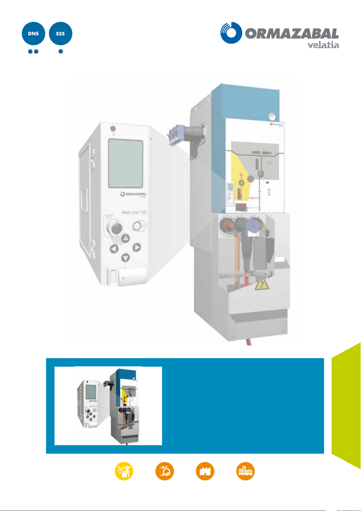
ekor.rpa
Protection, metering and control
multifunction unit
General Instructions
IG-267-EN, version 01, 07/04/2017
LIB

CAUTION!
When medium-voltage equipment is operating, certain components are live, other parts may be in movement and some may
reach high temperatures. Therefore, the use of this equipment poses electrical, mechanical and thermal risks.
In order to ensure an acceptable level of protection for people and property, and in compliance with applicable environmental
recommendations, Ormazabal designs and manufactures its products according to the principle of integrated safety, based on
the following criteria:
• Elimination of hazards wherever possible.
• Where elimination of hazards is neither technically nor economically feasible, appropriate protection functions are
incorporated in the equipment.
• Communication about remaining risks to facilitate the design of operating procedures which prevent such risks,
training for the personnel in charge of the equipment, and the use of suitable personal protective equipment.
• Use of recyclable materials and establishment of procedures for the disposal of equipment and components so
that once the end of their service lives is reached, they are duly processed in accordance, as far as possible, with the
environmental restrictions established by the competent authorities.
Consequently, the equipment to which the present manual refers complies with the requirements of section 11.2 of Standard
IEC 62271-1. It must therefore only be operated by appropriately qualified and supervised personnel, in accordance with the
requirements of standard EN 50110-1 on the safety of electrical installations and standard EN 50110-2 on activities in or near
electrical installations. Personnel must be fully familiar with the instructions and warnings contained in this manual and in other
recommendations of a more general nature which are applicable to the situation according to current legislation
The above must be carefully observed, as the correct and safe operation of this equipment depends not only on its design but also
on general circumstances which are in general beyond the control and responsibility of the manufacturer. More specifically:
• The equipment must be handled and transported appropriately from the factory to the place of installation.
• All intermediate storage should occur in conditions which do not alter or damage the characteristics of the equipment
or its essential components.
• Service conditions must be compatible with the equipment rating.
• The equipment must be operated strictly in accordance with the instructions given in the manual, and the applicable
operating and safety principles must be clearly understood.
• Maintenance should be performed properly, taking into account the actual service and environmental conditions in
the place of installation.
The manufacturer declines all liability for any significant indirect damages resulting from violation of the guarantee, under any
jurisdiction, including loss of income, stoppages and costs resulting from repair or replacement of parts.
[1]
.
Warranty
The manufacturer guarantees this product against any defect in materials and operation during the contractual period. In the
event that defects are detected, the manufacturer may opt either to repair or replace the equipment. Improper handling of this
equipment and its repair by the user shall constitute a violation of the guarantee.
Registered Trademarks and Copyrights
All registered trademarks cited in this document are the property of their respective owners. The intellectual property of this manual
belongs to Ormazabal.
[1]
For example, in Spain the “Regulation on technical conditions and guarantees for safety in high-voltage electrical installations” – Royal Decree
337/2014 is obligatory.
In view of the constant evolution in standards and design, the characteristics of the elements contained in this manual are subject
to change without prior notice. These characteristics, as well as the availability of components, are subject to confirmation by
Ormazabal.

General Instructions
ekor.rpa
Contents
Contents
1. General description ..................................................5
1.1. General operating features ...................6
1.2. Components.................................7
1.2.1. Electronic relay ..............................8
1.2.2. Current sensors ..............................9
1.2.3. Voltage sensors ..............................9
1.2.4. “Binox” bistable tripping device and
tripping coil ................................10
1.3. Functionality of the unit.....................10
1.4. Communications............................11
2. Applications .............................................................12
2.1. Remote control of transformer and
distribution substations .....................12
2.2. Automatic reclosing of lines .................12
2.3. Line protection with circuit-breaker..........13
2.4. Transformer protection......................14
2.5. Automatic transfer . . . . . . . . . . . . . . . . . . . . . . . . . .16
2.6. Detection of phase with earthing............16
2.7. Protection and control of
MV interconnection stations.................17
2.8. Energy balances ............................17
3. Metering functions ..................................................18
3.1. Current and voltage metering ...............18
3.2. Power meterings............................19
3.3. Energy meter ...............................19
4. Protection functions ................................................20
4.1. Overcurrent units ...........................20
4.1.1. Timed overcurrent units.....................20
4.1.2. Instantaneous overcurrent units.............21
4.1.3. Block diagram ..............................21
4.2. Ultra-sensitive earth.........................22
4.3. Directional units ............................23
4.3.1. Phase directional units ......................23
4.3.2. Neutral and sensitive neutral
directional units ............................24
4.4. Thermal image unit .........................25
4.4.1. Estimated thermal capacity..................26
4.4.2. Functionality................................27
4.4.3. Block diagram ..............................28
4.5. Broken conductor unit ......................29
4.5.1. Calculation of sequence currents ............29
4.5.2. Functionality................................32
4.5.3. Block diagram ..............................32
4.6. Voltage units ...............................33
4.6.1. Timed overvoltage units ....................34
4.6.2. Instantaneous overvoltage units.............34
4.6.3. Timed undervoltage units...................35
4.6.4. Instantaneous undervoltage units ...........35
4.6.5. Block diagram ..............................36
4.7. Second harmonic blocking unit .............37
4.7.1. Functionality................................37
4.7.2. Block diagram ..............................39
4.8. Block by I
5. Detection, automation and control functions .......42
5.1. Recloser automation ........................42
5.1.1. Functionality................................42
5.1.2. VREF........................................42
5.1.3. Settings ....................................43
5.1.4. Recloser statuses............................43
5.2. Voltage presence/absence automation ......45
5.2.1. Functionality................................45
5.2.2. Settings ....................................45
5.2.3. Voltage presence/absence
automation statuses ........................45
5.3. Switch control ..............................46
5.3.1. Introduction . . . . . . . . . . . . . . . . . . . . . . . . . . . . . . . .46
5.3.2. Settings ....................................46
5.3.3. Switch control statuses......................47
5.4. Remote control .............................47
6. Sensors ......................................................................48
6.1. Current sensors .............................48
6.1.1. Functional characteristics
of current sensors...........................49
6.1.2. Vector sum/zero-sequence wiring ...........50
6.2. Voltage sensors .............................51
6.2.1. Bushing ....................................51
6.2.2. ekor.evt-c ..................................52
7. Technical characteristics of the equipment ...........53
7.1. Rated values ................................53
7.2. Mechanical design ..........................53
7.3. Insulation tests..............................54
7.4. Electromagnetic compatibility...............54
7.5. Climatic tests ...............................55
7.6. Mechanical tests ............................55
7.7. Power tests .................................55
7.8. CE Conformity ..............................55
.................................41
max
IG-267-EN versión 01; 07/04/2017
3

Contents General Instructions
ekor.rpa
8. Protection, metering and control models .............56
8.1. Description of models vs functions ..........56
8.1.1. ekor.rpa-110................................58
8.1.2. ekor.rpa-120................................58
8.1.3. ekor.rpa-100-v/ekor.rpa-100-p..............59
8.1.4. Relay configurator ..........................60
8.2. “v” ekor.rpa-110-v and ekor.rpa-120-v
type units...................................61
8.2.1. Functional description ......................61
8.2.2. Definition of digital inputs/outputs .........62
8.2.3. Installation in a cubicle......................63
8.2.4. Checking and maintenance .................64
8.3. “p” ekor.rpa-110-p and ekor.rpa-120-p
type units ..................................66
8.3.1. Functional description ......................66
8.3.2. Definition of digital inputs/outputs ..........67
8.3.3. Fuse protection . . . . . . . . . . . . . . . . . . . . . . . . . . . . .68
8.3.4. Installation in a cubicle......................71
8.3.5. Checking and maintenance .................72
9. User configuration settings .....................................73
9.1. Local protection and automation settings ...73
9.2. Date and time settings ......................79
9.3. Remote communication settings ............79
11. User interface ...........................................................85
11.1. Web server. Checking and
configuring parameters .....................85
11.1.1. Characteristics of the Web server ............85
11.1.2. Access to the Web server: Local and
remote access ..............................86
11.2. Keyboard/Display ..........................90
11.2.1. Introduction . . . . . . . . . . . . . . . . . . . . . . . . . . . . . . . .90
11.2.2. Display screen ..............................91
11.2.3. Error codes .................................96
11.3. Fileserver in USB memory ...................97
11.3.1. Connection to the system ...................97
11.3.2. Use of the interface .........................98
11.3.3. ekor.soft-xml ............................. 100
12. Communications ................................................... 102
12.1. Physical medium: RS-485.................. 102
12.1.1. MODBUS protocol ........................102
12.1.2. PROCOME protocol .......................107
12.2. Physical medium: Ethernet ................110
12.3. Physical medium: Mini-USB................111
13. Annex ..................................................................... 112
10. Log record .................................................................80
10.1. Fault report ................................80
10.1.1. Data capture logic ..........................80
10.1.2. Structure of the report ......................81
10.1.3. List of available signals .....................82
10.2. Event record ................................84
4
IG-267-EN versión 01; 07/04/2017
General Instructions
ekor.rpa
1. General description
General description
Within the ekor.sys family, the ekor.rpa range of protection,
metering and control units groups together a series of
multifunctional devices. Depending on the model, the
equipment can incorporate voltage and current functions,
along with automation functions, local/remote control,
etc. All these functions are related to current and future
automation, control and protection requirements in
switching and transformer substations.
As a result of new demands in supply quality, there is an
increasing need for automation in distribution networks
and for equipment to carry out metering and control
supervision functions for the switch in distribution cubicles.
The ekor.rpa-100 protection, metering and control units
have been designed to meet these needs, in accordance
with national and international standard requirements and
recommendations that are applied to each part that makes
up the unit:
• EN 60255, EN 61000, EN 62271-200, EN 60068, EN 60044.
• IEC 60255, IEC 61000, IEC 62271-200, IEC 60068, IEC 60044,
IEC 61958.
Integrating the ekor.rpa units in the Ormazabal cubicle
system allows specific products for requirements in different
facilities.
2. Delivering the complete integrated solution (cubicle +
relay + sensors) reduces handling of interconnections
when installing the cubicle in the network connection.
The only connection necessary is the medium-voltage
cables (MV). The possibility of wiring and installation
errors is removed, thus minimising commissioning time.
3. Voltage and current sensors are installed in the cubicle
cable bushing. Metering of V, I, P, Q and energies are
obtained without the need for voltage transformers.
4. All the units are factory installed, adjusted and checked;
each piece of equipment (relay + control + sensors)
also undergoes a comprehensive check before being
installed. The final unit tests are carried out once the
unit is incorporated in the cubicle before delivery.
5. Current metering is carried out by current sensors
with a high transformation ratio, making it possible for
the same equipment to detect a wide range of power
levels. This is possible thanks to the high sensitivity and
low noise of the relay's analogue channels.
The ekor.rpa-100 units in the ekor.rpa range have outputs
to, either locally or remotely, open and close the switch
in the cubicle where it is installed. Furthermore, the
equipment series has inputs which receive the status of the
cubicle switch.
The ekor.rpa-100 units also have the following benefits
compared to conventional systems:
1. The remote control unit (RTU or Remote Terminal Unit)
and protection are integrated in the cubicle in a compact
manner, simplifying the solution and minimising the
need to install control boxes on the cubicles.
Figure 1.1. Protection, metering and control units: ekor.sys family
IG-267-EN versión 01; 07/04/2017
5
General description General Instructions
ekor.rpa
1.1. General operating features
All the relays of the ekor.rpa-100 series include a
microprocessor for processing the metering sensor signals.
They process voltage and current meterings and eliminate
the influence of transient states, calculate the magnitudes
required to ensure current and voltage protection functions,
automation, etc. At the same time they calculate the
efficient values of the electrical meterings that report the
instantaneous value of these parameters of the installation.
Figure 1.2. ekor.rpa-100 series relay
The ekor.rpa-100 relays are equipped with a keypad for
local display, set-up and operation of the unit, as well as
communication ports to handle these functions from a PC,
either locally or remotely. The ergonomic keyboard menus
have been designed to make use as intuitive as possible.
Current metering is carried out via high transformation
ratio current sensors. These transformers or current sensors
maintain the accuracy class in all of their rated range.
Voltage metering is normally by capturing the voltage
signal using a capacitor divider built into the cubicle's
bushing. There is an option of installing ekor.evt-c external
capacitive voltage sensors for applications which require
high-voltage metering precision, such as applications with
MV network energy meters.
The different interfaces, local (display) or remote (Web), also
provide settings parameters, logs, events, etc., in addition
to instantaneous values for metering of currents, voltages,
powers and energies.
From a maintenance perspective, the ekor.rpa-100 units
have a series of features that reduce the time and the
possibility of errors in the test and service restoration tasks.
Among the main characteristics, the most prominent are
the large diameter toroidal-core current transformers
installed in the cubicle bushing, their built-in test bars
(for easier checking), and accessible terminal blocks for
current or voltage injection tests as well as for checking
the relay inputs and outputs. This configuration enables a
comprehensive testing of the unit.
6
IG-267-EN versión 01; 07/04/2017
General Instructions
ekor.rpa
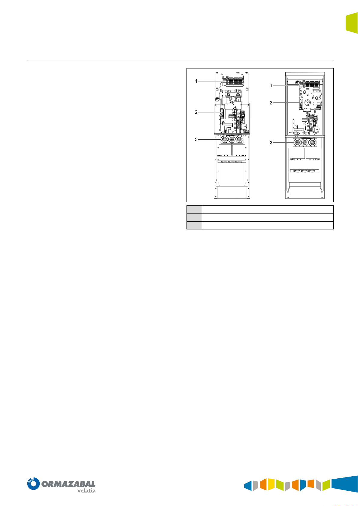
1.2. Components
The parts which make up the ekor.rpa-100 protection,
metering and control series are the electronic relay, voltage
and current sensors, auxiliary circuits (terminal block and
wiring), the bistable release and the tripping coil.
General description
Terminal block
1
ekor.rpa electronic relay
2
Voltage and current sensors
3
Figure 1.3. Parts of the assembly of ekor.rpa-100 in cubicle
IG-267-EN versión 01; 07/04/2017
7
General description General Instructions
ekor.rpa
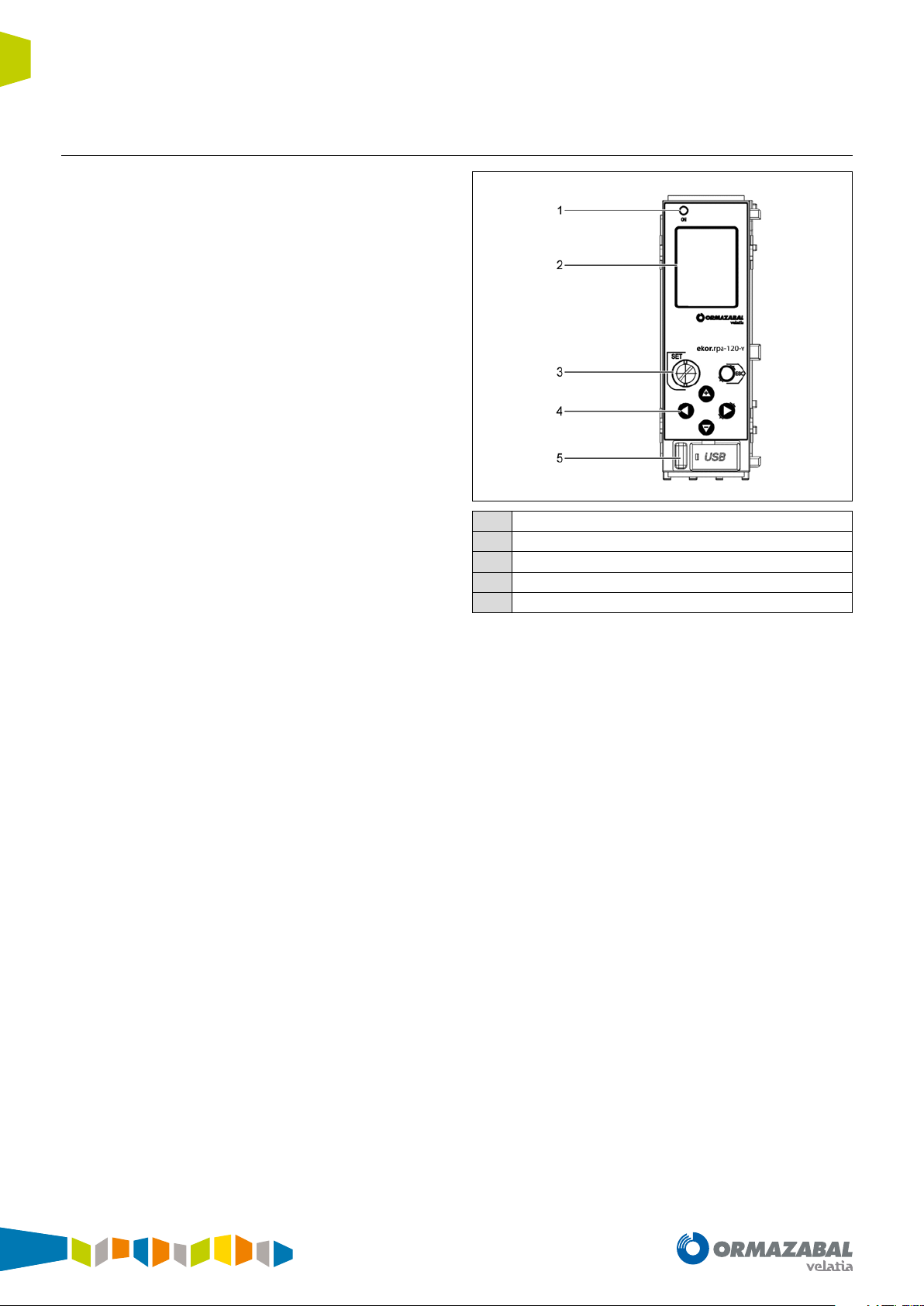
1.2.1. Electronic relay
The electronic relay has a keyboard and display to set and
view the protection and control parameters. Moreover, the
display provides information of the system's meterings,
alarms and control signals in real time. The keyboard
includes a seal on the <<SET>> key to ensure that once the
settings have been made they cannot be changed unless
the seal is broken.
The protection trips are registered on the display with the
following parameters:
• Trip unit
• The phasor at the moment of tripping (currents and
voltages).
• Tripping time. The time passing from start-up to tripping
of the unit.
• The time and date the event occurred.
Unit errors are also permanently displayed. Furthermore, it
is possible to check the fault reports using the front USB port
by connecting a PC to this port and using the implemented
folder system.
The “ON” LED is activated when the equipment receives
power from an external source and flashes quickly when
the relay starts up. This LED will flash less frequently
once the microprocessor has checked that the status of
the equipment is correct and all the protection units are
active. In this situation, the unit is operational to carry out
protection functions.
The voltage and current analogue signals are conditioned
internally by small and very accurate transformers that
isolate the electronic circuits from the rest of the installation.
The system has, in all its variants, 9 inputs and 4 outputs.
Both the inputs and the outputs are protected from
unwanted enabling/disabling.
The unit has 2 rear Ethernet ports for configuration, a
front mini-USB port for maintenance, and two rear RS-485
communications ports for remote control. The standard
communication protocols for all models are MODBUS and
PROCOME.
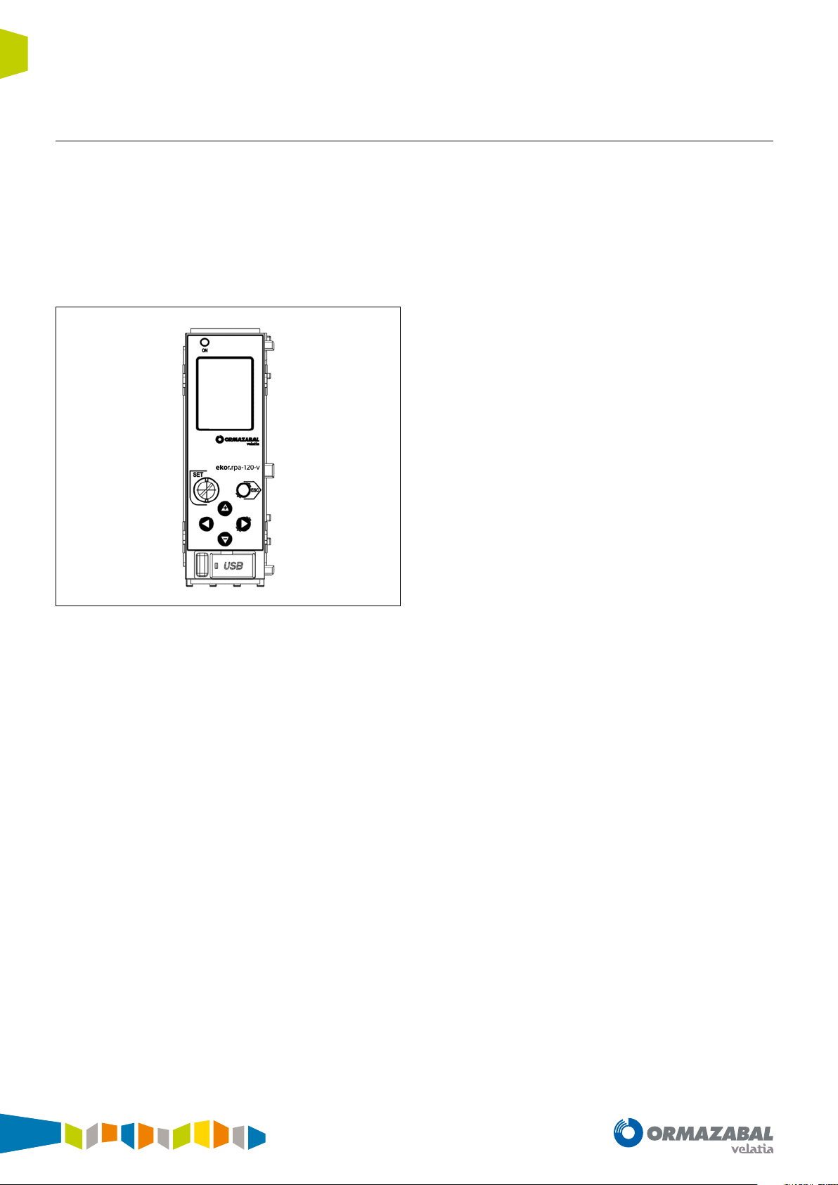
"ON" signalling LED
1
Metering and parameter setting display
2
SET key
3
Keyboard for scrolling through screens
4
Front mini-USB communication port
5
Figure 1.4. Description of the elements available on the front of the
ekor.rpa-120 relay
8
IG-267-EN versión 01; 07/04/2017

General Instructions
ekor.rpa
1.2.2. Current sensors
The current sensors are toroidal-core current transformers
with a 300/1 A or 1000/1 A or 2500/1 ratio, depending on
the models. These transformers cover the entire operation
range of Ormazabal cubicles, from rated currents 5A up to
2500 A.
The phase toroidal transformers are factory-installed in
the cubicle bushings, which significantly simplifies on-site
assembly and connection. This way, once the mediumvoltage cables are connected to the cubicle, the installation
protection is operational. Installation errors of the sensors,
due to earth grids, polarities, etc., are removed upon
installation and checked directly at the factory.
All the current sensors have an integrated protection
against the opening of secondary circuits, which prevents
overvoltages.
General description
1.2.3. Voltage sensors
Cubicle voltage metering is carried out using a capacitor
divider incorporated in the cubicle’s bushing, which ensures
a precision of ± 5 % in the worst case scenario.
Ormazabal ekor.evt-c capacitive sensors can be used
for greater precision. These are capacitor divider voltage
sensors for gas-insulated cubicles. They are designed to
allow assembly in both separable T-connectors and busbars.
Their operation is autonomous and passive (without
external auxiliary supply), with low-voltage analogue
output and low power applicable directly to the metering
systems without prior conditioning, for installation in
medium-voltage automation and supervision systems in
networks up to 36 kV. It can also measure partial discharges
and establish communication via PLC.
Bushing
1
Current sensors
2
Figure 1.5. Location of the current sensors
Figure 1.6. ekor.evt-c voltage sensors
IG-267-EN versión 01; 07/04/2017
9

General description General Instructions
ekor.rpa
1.2.4. “Binox” bistable tripping device and tripping coil
The "Binox" bistable trigger is a precision electromechanical
actuator which is sealed with its own reinforcement and
integrated in the switch driving mechanism. This release
acts upon the switch when there is a protection trip. It is
characterised by the low actuation power (high energy
efficiency) it requires for tripping. This energy is delivered in
the form of a pulse from the relay in a controlled manner to
ensure the proper operation of the release and the opening
of the switch.
The trials and tests passed by the ekor.rpa-100 unit set and
cubicle, along with quality assurance in manufacture, mean
this is a highly reliable element in the tripping chain. The
solutions presented by Ormazabal with ekor.rpa-100 units
have this tripping device installed as standard.
Figure 1.7. “Binox” Tripping coil
The operations ordered by the ekor.rpa-100 unit digital
outputs are performed by means of conventional tripping
coils. This way, a redundant and therefore more reliable
operational system is achieved.
1.3. Functionality of the unit
The functionality of the assembly as a unit (MV cubicles for
protection, metering and control, sensors, and protection
and metering transformers) is validated in a test plan carried
out in an in-house controlled environment.
To achieve this, Ormazabal counts on the CIT, its Research
and Technology Centre, which represents an essential
instrument in R&D, in order to capture and improve existing
technologies and carry out research into new ones.
The CIT facilities offer services to the science and technology
sector in order to carry out research, development and type
tests both for Ormazabal's business unit products and also
for the rest of the electricity sector.
The CIT is made up mainly of:
1. HPL: Electrotechnical power laboratory, with the goal
of identifying, acquiring and disseminating process
technologies and strategic products within Ormazabal.
2. UDEX: Demonstration and experimentation unit
consisting of a fully configurable, independent
medium-voltage singular experimentation network to
allow tests for new technologies, products and services
to be developed and carried out in a safe, controlled
environment.
10
IG-267-EN versión 01; 07/04/2017
General Instructions
ekor.rpa
1.4. Communications
All the relays of the ekor.rpa-100 units have two TCP/IP
connection Ethernet ports and a Web server for
configuration. They also have a front mini-USB port for
maintenance and two rear ports with serial communication
RS-485 twisted pair (COM0 and COM1) for remote control.
The standard communication protocols implemented in all
equipment are MODBUS in RTU transmission mode (binary)
and PROCOME, through the rear RS-485 COM0 port fitted in
these units.
Optionally, the ekor.rpa-120 model also has a bus for
temperature sensor connection.
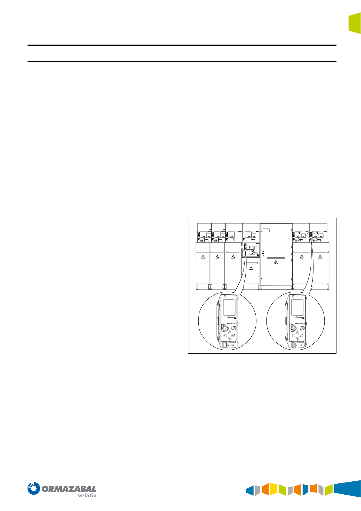
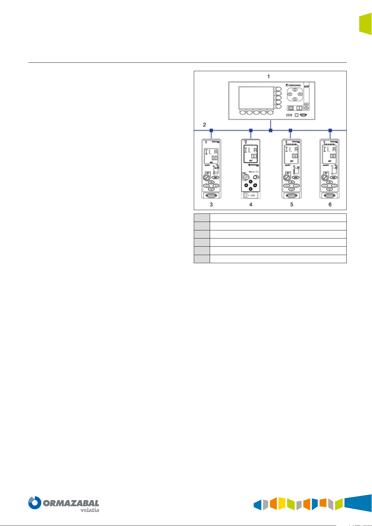
The ekor.rpa-100 relays can be interconnected to other
units in the ekor.sys family, as shown in the image below.
General description
ekor.ccp
1
ekor.bus
2
ekor.rci
3
ekor.rpa
4
ekor.rpt
5
ekor.rpg
6
Figure 1.8. Intercommunicated units of the ekor.sys family
IG-267-EN versión 01; 07/04/2017
11
Applications General Instructions
ekor.rpa
2. Applications
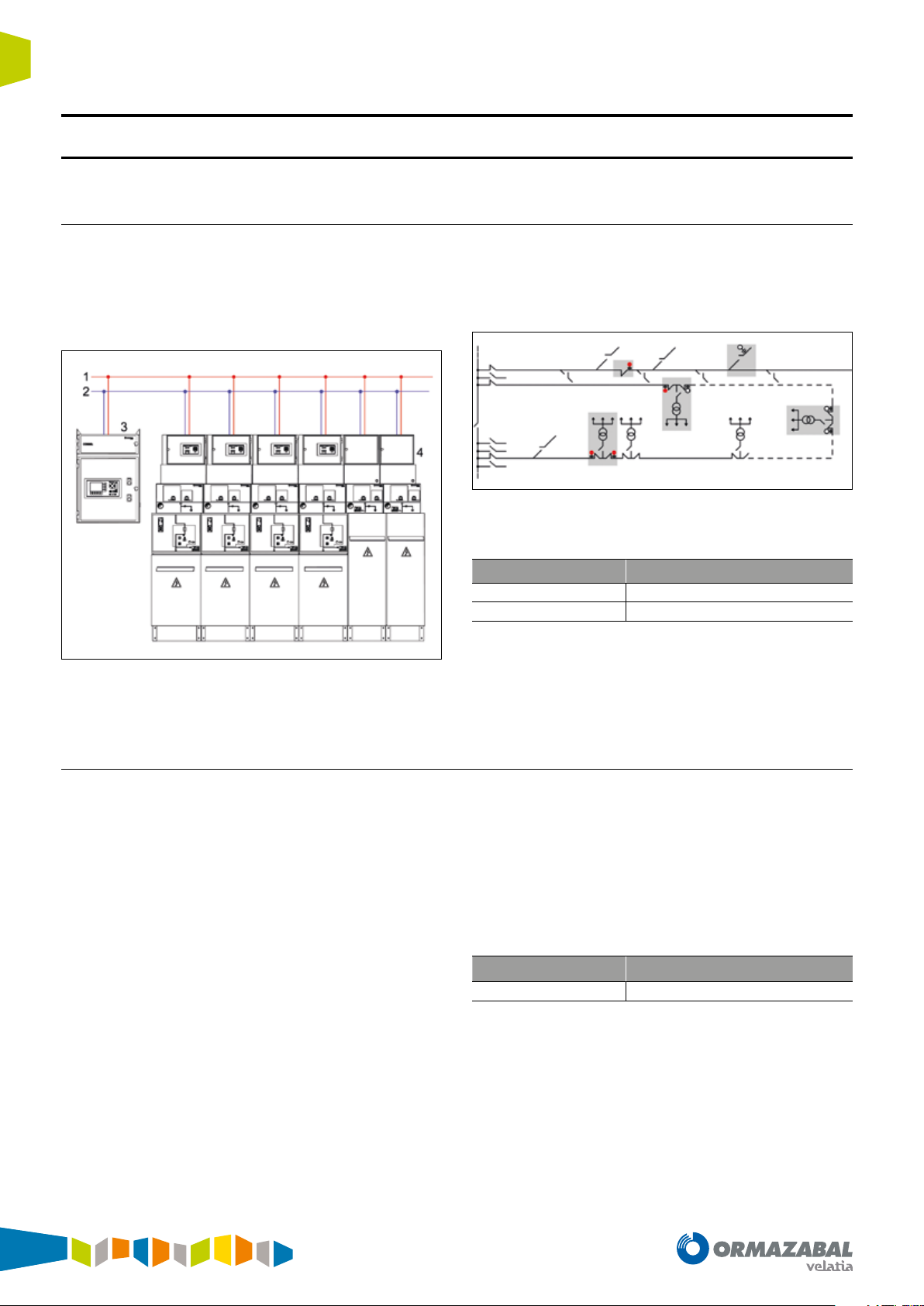
2.1. Remote control of transformer and distribution substations
The ekor.rpa-100 protection, metering and control units
make it possible to handle remote control applications of the
transformer and switching substations, by implementing
the control and monitoring of each switch through the
units associated with each functional unit.
Figure 2.1. Remote-controlled switching substation
The use of a remote control terminal and ekor.rpa-100 units
enable the user to visualise and operate each functional
unit remotely thanks to the inputs and outputs fitted for
this purpose.
Figure 2.2. Layout of dierent stations in the network
Units that include this remote control function:
Unit Type of cubicle
ekor.rpa-100 type = p
ekor.rpa-100 type = v
Table 2.1. Remote control function units
Fuse-combination switch
Circuit-breaker
The remote controlling applications complement the
ekor.rci integrated control unit associated to feeder
functions (see Ormazabal document IG-158).
2.2. Automatic reclosing of lines
The reclosing function performs the automatic reclosing of
lines once the protection unit has commanded the trip and
the switch has opened.
This function is always associated with Ormazabal circuitbreaker cubicles.
The protection units with automatic reclosing have a series
of advantages over protections without reclosing:
• They reduce the time in which electrical power is
interrupted.
• They avoid the need to locally re-establish the service in
substations without remote control for transient faults.
• They reduce the fault time using a combination of fast
switch trips and automatic reclosings, which results in
lesser damage caused by the fault and generates a lower
number of permanent faults derived from transient faults.
The unit which includes this function is:
Unit Type of cubicle
ekor.rpa-100 type = v
Table 2.2. Recloser function unit
Circuit-breaker
12
IG-267-EN versión 01; 07/04/2017
General Instructions
ekor.rpa
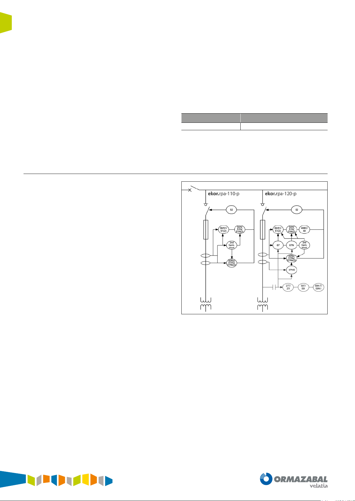
2.3. Line protection with circuit-breaker
Applications
The purpose of the line protection is to isolate this part
of the network in case of fault, without it affecting the
rest of the lines. In a general way, it covers any faults that
originate between the substation, transformer substation
or switching substation and the consumption points.
Figure 2.3. Feeder protection functions in ekor.rpa-100 relays
The types of fault that occur in these areas of the network
depend primarily on the nature of the line, overhead line or
cable and the neutral used.
In networks with overhead lines, the majority of faults are
transient, which makes many line reclosings effective; in
these cases, the reclosing function associated with circuitbreakers is used.
This is not the case for underground cables where faults are
usually permanent.
On the other hand, in case of phase-to-earth faults in
overhead lines, when the ground resistance is very high,
the zero-sequence fault currents have a very low value In
these cases, an ‘ultrasensitive’ neutral current detection is
required.
The underground cables have earth coupling capacities,
which causes the single phase faults to include capacitive
currents. This phenomenon makes detection difficult in
isolated or resonant earthed neutral networks and thus
requires the use of the directional function.
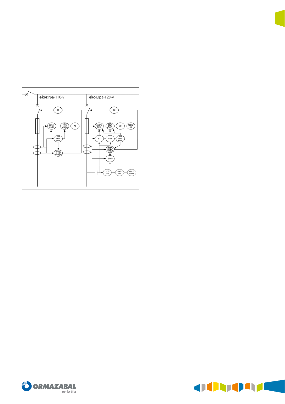
In ekor.rpa-100 units, model ekor.rpa-110, line protection
is carried out mainly by the following functions:
• 50 ≡ Instantaneous overcurrent relay. Protects against
short-circuits between phases.
• 51 ≡ Inverse time overcurrent relay. Protects against
excessive overloads, which can deteriorate the
installation.
• 51_2 ≡ Inverse time overcurrent relay II. Additional
step to protect against excessive overloads, which can
deteriorate the installation.
• 50N ≡ Instantaneous earth overcurrent relay. Protects
against phase-to-earth short-circuits.
• 51N ≡ Inverse time earth overcurrent relay. Protects
against highly resistive faults between phase and earth.
• 51_2_N ≡ Inverse time earth overcurrent relay II.
Additional step to protect against highly resistive faults
between phase and earth.
• 50NS ≡ Instantaneous sensitive earth overcurrent
relay. Protects against phase to earth short-circuits of
very low value.
• 51NS ≡ Inverse time sensitive earth overcurrent
relay. Protects against highly resistive faults between
phase and earth of very low value.
• 51_2_NS ≡ Inverse time sensitive earth overcurrent
relay II. Additional step to protect against highly
resistive faults between phase and earth of very low
value.
nd
• 2
Harm. Block ≡ Second harmonic blocking. Blocks
overcurrent units during transformer magnetisation
• 79 ≡ Reclosing relay. Enables the automatic reclosing
of lines.
IG-267-EN versión 01; 07/04/2017
13
Applications General Instructions
ekor.rpa
In addition, the ekor.rpa-100 equipment, ekor.rpa-120
model, also have the following functions:
• 67/67N and 67NS ≡ Directional overcurrent relay,
directional earth fault relay and directional sensitive
earth fault relay. Phase, neutral and sensitive neutral
directional functions which are associated to their
corresponding overcurrent units, together allowing
directional overcurrent units.
• 49 ≡ Machine or transformer thermal relay. Protects
against thermal overloads in lines which cannot be
detected by the overcurrent units.
• 46BC ≡ Broken conductor detection. Detects open
lines, which are generally quite difficult to detect using
overcurrent units.
2.4. Transformer protection
The distribution transformers require various protection
functions. Their selection depends primarily on the power
and level of responsibility they have in the installation.
• 59/59N ≡ Overvoltage and residual overvoltage
relay. Protects against phase and neutral overvoltages
in the lines with 2 units for each phase and neutral, one
timed and the other instantaneous.
• 27 ≡ Undervoltage relay. Protects against phase
undervoltages in the lines with 2 units for each phase,
one timed and the other instantaneous.
The units which provide the aforementioned functions are:
Unit Type of cubicle
ekor.rpa-100 type = v
Table 2.3. ekor.rpa-100-v
Circuit-breaker
14
Figure 2.4. Transformer protection functions in ekor.rpa-100 relays
IG-267-EN versión 01; 07/04/2017

General Instructions
ekor.rpa
Applications
The protection functions, available in models
ekor.rpa-110, which must be implemented to protect
distribution transformers with power ratings between 160
kVA and 2 MVA are the following:
• 50 ≡ Instantaneous overcurrent relay. Protects against
short-circuits between phases in the primary circuit, or
high value short-circuit currents between phases on the
secondary side. This function is performed by the fuses
when the protection cubicle does not include a circuitbreaker.
• 51 ≡ Inverse time overcurrent relay. Protects
against excessive overloads, which can deteriorate the
transformer, or against short-circuits in several turns of
the primary winding.
• 51_2 ≡ Inverse time overcurrent relay II. Additional
step to protect against excessive overloads, which can
deteriorate the transformer, or against short-circuits in
several turns of the primary winding.
• 50N ≡ Instantaneous earth overcurrent relay. Protects
against phase to earth short-circuits or secondary
winding short-circuits, from the interconnections and
windings in the primary.
• 51N ≡ Inverse time earth overcurrent relay. Protects
against highly resistive faults from the primary circuit to
earth or to the secondary circuit.
• 51_2_N ≡ Inverse time earth overcurrent relay II.
Additional step to protect against highly resistive faults
from the primary circuit to earth or to the secondary.
• 50NS ≡ Instantaneous sensitive earth overcurrent
relay. Protects against phase to earth short-circuits of
very low value.
• 51NS ≡ Inverse time sensitive earth overcurrent
relay. Protects against highly resistive faults between
phase and earth of very low value.
• 51_2_NS ≡ Inverse time sensitive earth overcurrent
relay II. Additional step to protect against highly resistive
faults between phase and earth of very low value. 2
nd
Harm. Block ≡ Second harmonic blocking. Blocks
overcurrent units during transformer magnetisation.
In addition, the ekor.rpa-100 equipment, ekor.rpa-120
models, also have the following functions:
• 67/67N and 67NS ≡ Directional overcurrent relay,
directional earth fault relay and directional sensitive
earth fault relay. Phase, neutral and sensitive neutral
directional functions which are associated to their
corresponding overcurrent units, together allowing
directional overcurrent units.
• 49 ≡ Machine or transformer thermal relay. Protects
against thermal overloads of transformers which cannot
be detected by the overcurrent units.
• 46BC ≡ Broken conductor detection. Detects open
lines. Broken conductors are quite difficult to detect
using overcurrent units.
• 59/59N ≡ Overvoltage relay and residual overvoltage
relay. Protects against phase and neutral overvoltages
in the lines with 2 units for each phase and neutral, one
timed and the other instantaneous.
• 27 ≡ Undervoltage relay. Protects against phase
undervoltages in the lines with 2 units for each phase,
one timed and the other instantaneous.
The protection units that include the above mentioned
functions are:
Unit Type of cubicle
ekor.rpa-100 type = p
ekor.rpa-100 type = v
Table 2.4. ekor.rpa-100-p/ekor.rpa-100-v
Fuse-combination switch
Circuit-breaker
IG-267-EN versión 01; 07/04/2017
15
Applications General Instructions
ekor.rpa
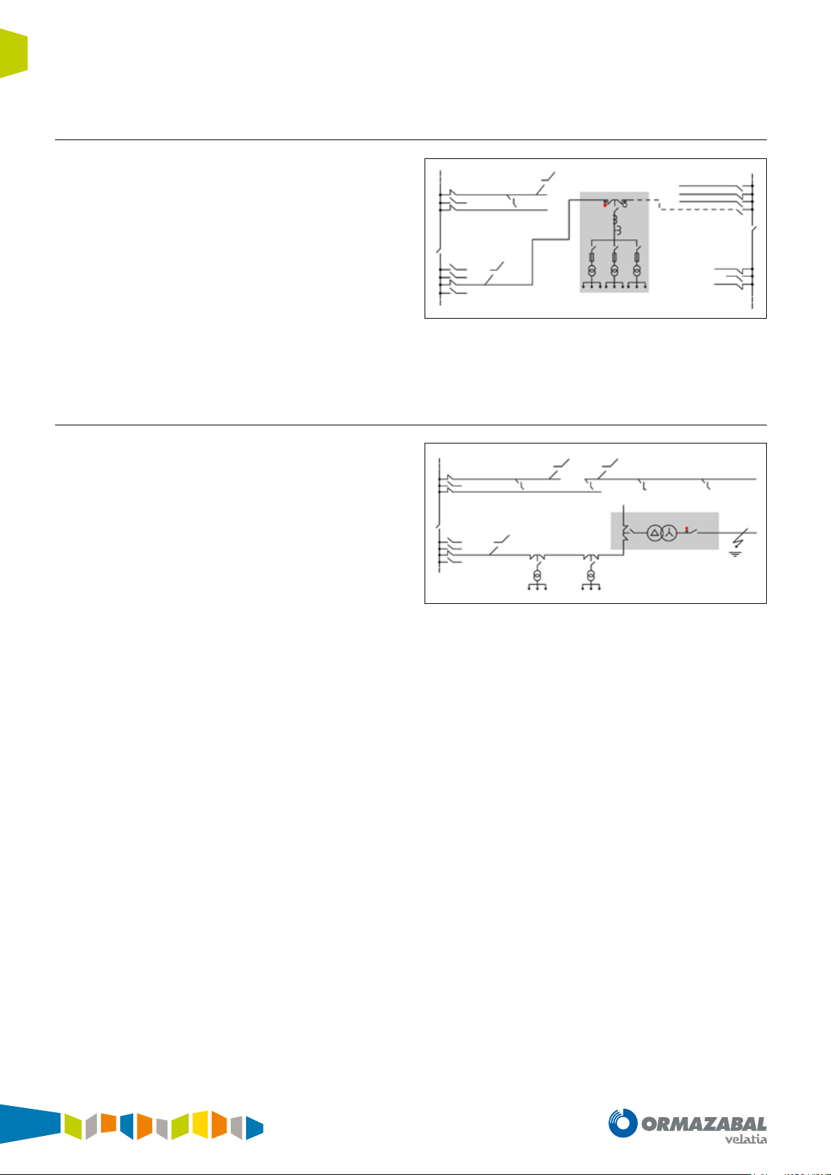
2.5. Automatic transfer
The automatic transfer of lines with circuit-breakers
minimises power outages in loads fed by transformer or
switching substations with more than one incoming line,
thereby improving continuity of service.
Under normal conditions with voltage present on two
possible incoming lines, the switch selected as preferred
remains closed and the reserve one is opened. A voltage
drop in the preferred line will cause the switch of this line
to open and the reserve switch to close afterwards. Once
normality has been re-established in the preferred line, the
inverse cycle is performed, and the system returns to its
initial status.
Figure 2.5. Automatic transfer
2.6. Detection of phase with earthing
In networks with isolated or resonant earthed neutral, the
fault currents are very low. In the event of a fault in a system
of this type, the fault current may not reach the calibrated
threshold for overcurrent protection, and therefore this
fault may not be detected.
Function 59 is used instead of programmed logic for
detecting this type of fault, analysing both the installation’s
neutral voltage and its current.
Figure 2.6. Detection of phase with earthing
16
IG-267-EN versión 01; 07/04/2017
General Instructions
ekor.rpa
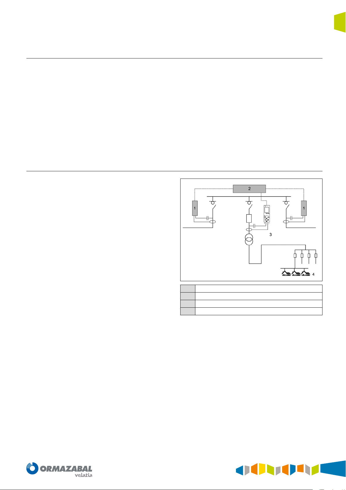
2.7. Protection and control of MV interconnection stations
Applications
In MV customers where an ekor.rpa-100 relay is installed,
either in protection cubicles with circuit-breaker or fuses
which protect the MV outgoing, information on this
outgoing can be sent to the SCADA both by the web and
via the MODBUS-TCP communications protocol.
2.8. Energy balances
By including MV energy meterings in the ekor.rpa-100
relays, it is possible to analyse non-technical losses which
can be found between the Transformer Substation and
the LV consumption, in order to uncover possible fraudulent
use such as energy which has not been billed due to an
error in the LV equipment.
The accessible information would be as follows:
• Cubicle position
• Trips
• Alarms
• Meterings:
- Voltage
- Current
- Power
- Energy
ekor.rci
1
ekor.ccp
2
ekor.rpa
3
Meters
4
Figure 2.7. ekor.rpa-100 unit measuring MV energies in a transformer
with private customers
IG-267-EN versión 01; 07/04/2017
17
Metering functions General Instructions
ekor.rpa
3. Metering functions
3.1. Current and voltage metering
The unit has four current reading inputs (IA, IB, IC and INS)
and three voltage reading inputs (VA, VB and VC). Each of
them are conditioned and digitised in order to carry out the
calculation.
The design of the equipment and sensors, along with their
integration in the cubicle, form an assembly which works
as a single unit to achieve maximum immunity and quality
of the signal to be measured, both in the 50 Hz and 60 Hz
networks.
The signal transduction and conditioning stages are
designed to ensure the sensor and relay assembly
reproduces both the magnitude and the phase of the
current and voltage signals of the distribution network.
This ensures optimal performance in real-time applications,
with protection algorithms, in all operation conditions and
in supply quality or load monitoring meterings.
The samples obtained for I
and VN, calculated by the sum
N
of samples of the corresponding phase signals, must be
added to the voltage and current inputs sampled directly.
These calculated signal characteristics are equivalent to
those obtained by vector sum of the conventional sensor
signals.
The meterings for supervision of current and voltage are
measured integrated for 1.28 seconds and represented in
phasorial mode (module + argument). Network load status
is therefore updated regularly.
The current and voltage meterings are:
• Line currents I
• Line voltage: U
, IB and IC.
A
, UBC and UCA and Line voltages: VA, VB
AB
and VC.
• Residual currents and voltages. Represented as: I
N/INS
(3Io) and VN (3Vo).
Figure 3.1. Current and voltage metering
The final calibration is the overall calibration of sensors,
metering equipment, cabling and switchgear, and is
validated in an exhaustive test plan carried out in a
controlled environment which reproduces the reality of the
medium-voltage electrical distribution network.
All this process includes different scenarios:
• Maximum electromagnetic interference and temperature
rise scenarios of the assembly, carried out at rated
switchgear current.
• Maximum thermal variation scenarios, carried out in a
climate chamber between -10 °C and 60 °C.
• Scenarios with highly aggressive transient disturbance,
power and lightning impulse tests with medium-voltage
levels.
• etc.
These tests conclude in points such as: the ratio of the
number of turns of the current transformers, impedance
of the voltage reading inputs, etc. All this is tested and
validated on the final solution delivered to the customer.
18
IG-267-EN versión 01; 07/04/2017
General Instructions
ekor.rpa
3.2. Power meterings
Metering functions
The powers which are monitored (locally or remotely) are
1.28 second integrated meterings of the calculated RMS
instantaneous values.
Accredited meterings in precision class guarantee reliability
in the values obtained.
The equipment acts as a metering station for load analysis
or electrical supply quality monitoring tasks. The monitored
meterings for active and reactive power are single-phase
and three-phase, and three-phase only for apparent power.
3.3. Energy meter
The equipment is fitted with an "Active and reactive electrical
energy meter" which meets the particular requirements for
static energy meters. This is an indirect connection threephase meter which, along with the voltage and current
metering sensors, form a medium-voltage (MV) meter.
The energy meter accumulates 100 meterings of powers
P and Q integrated in a semicircle (1 second for 50Hz and
1.2 seconds for 60Hz). In total, there will be four meters:
three single-phase (A phase, B phase and C phase) and one
three-phase.
The meterings are made up of:
• Single-phase: Active PA, PB and PC and Reactive QA, QB
and QC.
• Three-phase: PT, QT and ST Powers and Power Factor
(P.F.).
Each meter has two active energy records (E+ and E-) and
four reactive energy records (Q1, Q2, Q3 and Q4), each of
them 32 bits. These registers have a bit to indicate overflow
and a reset option by command.
Active powers are expressed in kilovolts-hour (kWh) and
reactive powers are expressed in kilovolt amperes reactivehour (kVArh).
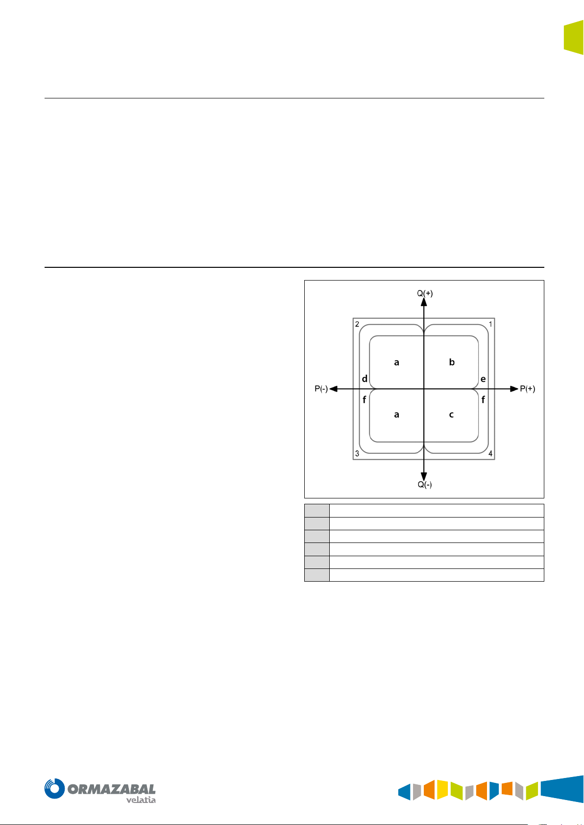
Reactive
a
Inductive
b
Capacitive
c
Generated
d
Consumed
e
Active
f
Active energy imported (in kWh): EA + , EB + , EC + and ET +
Active energy exported (kWh): EA - , EB - , EC - and ET Inductive reactive energy imported (kVArh): QA1, QB1, QC1 and QT1
Capacitive reactive energy imported (kVArh): QA2, QB2, QC2 and QT2
Inductive reactive energy exported (kVArh): QA3, QB3, QC3 and QT3
Capacitive reactive energy exported (kVArh): QA4, QB4, QC4 and QT4
Figure 3.2. Energies
IG-267-EN versión 01; 07/04/2017
19

Protection functions General Instructions
ekor.rpa
4. Protection functions
4.1. Overcurrent units
The ekor.rpa-100 systems are fitted with the following
overcurrent protection units:
Phases:
• Six phase overcurrent timed units (3 x 51.3 x 51(2)).
• Three phase overcurrent instantaneous units (3 x 50).
4.1.1. Timed overcurrent units
The phase, neutral and sensitive neutral timed units start
up if the fundamental value of the magnitude for each unit
exceeds the value 1.05 times the adjusted start-up, and are
reset when this value is below 0.95 times the adjusted value.
Tripping takes place if the unit is started up for the time set.
This time may be adjusted by selecting different types of
curve, in accordance with IEC and ANSI Standards.
The curves implemented in the ekor.rpa-100 units are:
IEC CURVES
• IEC DT: Defined time
• IEC NI: Normally inverse curve
• IEC VI: Very inverse curve
• IEC EI: Extremely inverse curve
• IEC LTI: Long time inverse curve
• IEC STI: Short time inverse curve
ANSI CURVES
• ANSI LI: Long time inverse curve
• ANSI NI: Normally inverse curve
• ANSI VI: Very inverse curve
• ANSI EI: Extremely inverse curve
These curves are detailed in the ANNEX section.
Neutral (Calculated):
• Two neutral timed overcurrent units (1 x 51N, 1 x 51(2)
N).
• A neutral instantaneous overcurrent unit (1 x 50N).
Sensitive neutral (measured):
• Two sensitive neutral timed overcurrent units (1 x 51NS,
1 x 51(2)NS).
• A sensitive neutral instantaneous overcurrent unit (1 x
50NS).
The settings for the timed units are:
• Enabling the unit: Enable/disable the unit (ON/OFF).
• Starting up the unit: Unit starting current. Variable
ranges in accordance with current transformers used.
• Time curve: Curve type (IEC DT, IEC NI, IEC VI, IEC EI, IEC
LTI, IEC STI, ANSI LI, ANSI NI, ANSI VI, ANSI EI).
• Time index: Time index, also known as time dial (from
0.05 to 1.60). This setting applies to all curve types
except for IEC DT.
• Fixed time: Unit tripping time (from 0.00 s to 100.00 s).
This setting only applies to IEC DT type curves.
• Torque control: Directional tripping mask (OFF,
FORWARD or REVERSE). To indicate the direction for
tripping:
- OFF: Regardless of the direction, the relevant
overcurrent unit will trip if the overcurrent conditions
are met.
- FORWARD: The corresponding overcurrent unit
will trip whenever the overcurrent conditions are
met, and the directional unit will give the FORWARD
signal.
- REVERSE: The corresponding overcurrent unit will
trip whenever the overcurrent conditions are met,
and the directional unit will give the REVERSE signal.
This setting will only be found in ekor.rpa-100 units
model 120.
20
IG-267-EN versión 01; 07/04/2017
General Instructions
ekor.rpa
4.1.2. Instantaneous overcurrent units
Protection functions
The phase, neutral and sensitive neutral instantaneous
units start up if the fundamental value of the magnitude for
each unit exceeds the value 1.00 times the adjusted startup, and are reset when this value is below 0.95 times the
adjusted value.
Tripping takes place if the unit is started up for the time set.
The settings for the instantaneous units are:
• Enabling the unit: Enable/disable the unit (ON/OFF).
• Starting up the unit: Unit starting current. Variable
ranges in accordance with current transformers used.
• Fixed time: Unit tripping time (from 0.00 s to 100.00 s).
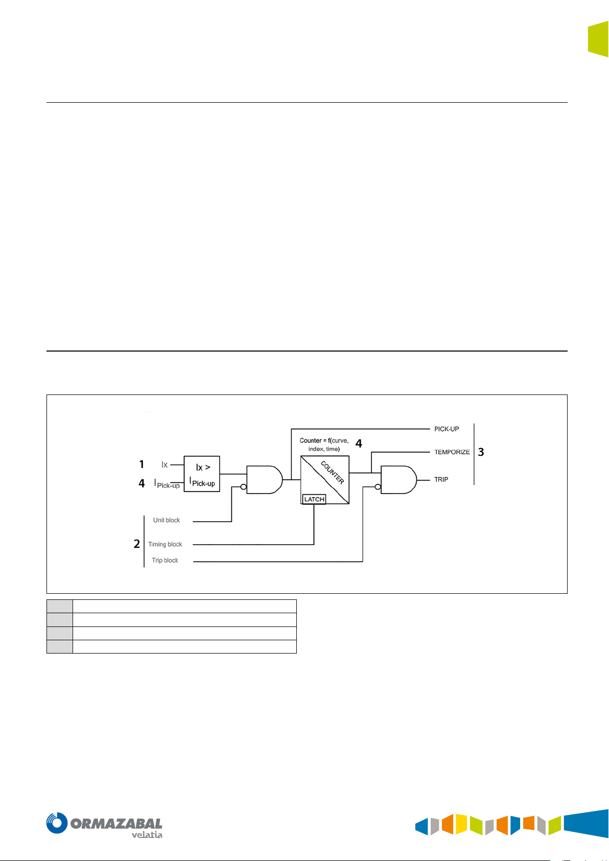
4.1.3. Block diagram
Any overvoltage unit complying with the diagram shown
below:
• Torque control: Directional tripping mask (OFF,
FORWARD or REVERSE). To indicate the direction for
tripping:
- OFF: Regardless of the direction, the relevant
overcurrent unit will trip if the overcurrent conditions
are met.
- FORWARD: The corresponding overcurrent unit
will trip whenever the overcurrent conditions are
met, and the directional unit will give the FORWARD
signal.
- REVERSE: The corresponding overcurrent unit will
trip whenever the overcurrent conditions are met,
and the directional unit will give the REVERSE signal.
This setting will only be found in ekor.rpa-100 units
model 120.
Metering
1
Input signal
2
Output signal
3
Settings
4
Figure 4.1. Block diagram
IG-267-EN versión 01; 07/04/2017
21
Protection functions General Instructions
ekor.rpa
Basically, the diagram shows that, whenever a magnitude
measured in real-time (Ix) exceeds the setpoint value (l
pick up
setting), a time counter counts down (counter: f (curve,
index, time), tripping when completely expired.
If the measured magnitude (Ix) drops below the setpoint
(I
) during timing, the unit and the meter are reset and
pick up
the unit remains idle.
All the units generate the following signalling:
• Pick-up: Activated when the measured magnitude (Ix)
exceeds a setpoint (I
setting) and disabled when the
pick up
metering value drops below the setpoint.
• Temporize: Activated when the time counter reaches
its end, and disabled when the metering value drops
below the setpoint.
• Trip: Activated when the temporize signal is activated,
and disabled when the metering value drops below the
setpoint.
4.2. Ultra-sensitive earth
This functionality is available in both directional and nondirectional ekor.rpa and corresponds to a particular case of
overcurrent detection for phase-to-earth faults. Primarily
used in networks with isolated neutral, resonant earthed
neutral or on highly resistive soils, where the phase-toearth fault current has a very low value.
Moreover, the overcurrent units can be blocked by the
maximum current blocking and second harmonic
blocking units detailed in the following sections.
Moreover, the overcurrent units can be blocked in three
different ways:
• Unit block: Blocks the unit, preventing start-up while
this input remains active.
• Timing Block: Freezes the time counter value while this
input is active.
• Trip Block: Allows the unit to advance, and blocks it
before the trip output.
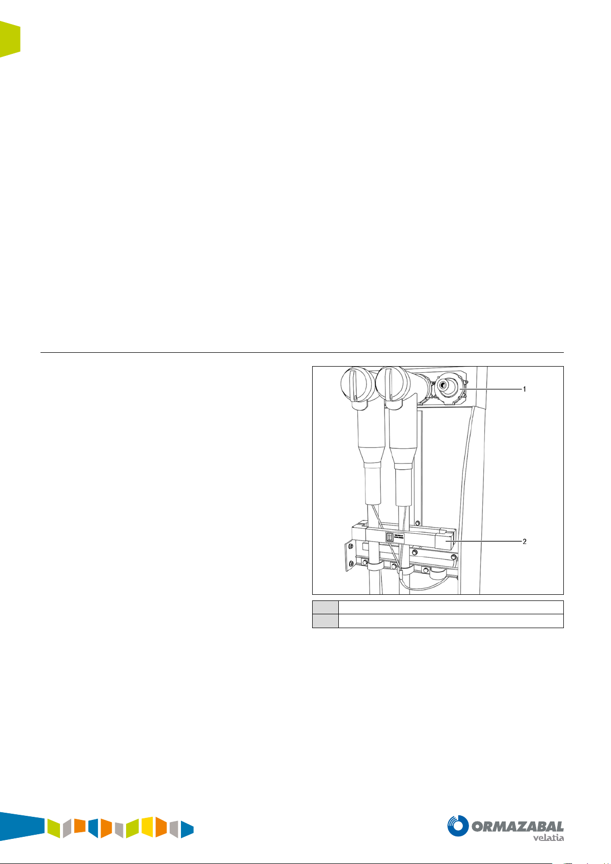
The current flowing to earth is detected using a toroidalcore current transformer which covers the three phases.
In this way, the metering is independent from the phase
current, thus avoiding errors in the phase metering sensors.
Using this type of toroidal-core means the measured
neutral currents due to unbalanced phases are reliable in
very low primary amp values. For this type of configuration,
the unit allows a minimum trip setting of 0.3 primary amps
in its Sensitive Neutral channel.
Voltage and current sensors
1
Zero-sequence transformers
2
Figure 4.2. Current sensors
22
IG-267-EN versión 01; 07/04/2017
General Instructions
ekor.rpa
4.3. Directional units
Protection functions
The directional units are combined with the overcurrent
units when taking a decision on tripping. In accordance with
the "torque control" direction setting (Forward or Reverse)
and the result of the direction of the fault, the overcurrent
units finish by tripping or not.
4.3.1. Phase directional units
Angular criterion
The phase directional units are units which, using the
angular criterion, determine the direction of each of the
3 phases. The polarisation voltage used for each phase is the
compound voltage corresponding to the other 2 phases.
These units determine direction based on:
• The calibrated settings.
• The phase difference existing between the polarisation
signal and the current signal.
The settings for the phase directional unit are:
The ekor.rpa-100 model 120 systems have the following
directional units:
• Three phase directional units (3 x 67)
• A neutral directional unit (1 x 67N)
• A sensitive neutral directional unit (1 x 67NS)
The Reverse direction zone will be the opposite of the
Forward zone. In other words, the above formula needs to
be turned around 180° in order to achieve the expression
which delimits the Reverse direction zone.
The directional units will indicate ndef direction if in the
indeterminate zone or polarisation voltage is below the
V
setting.
min
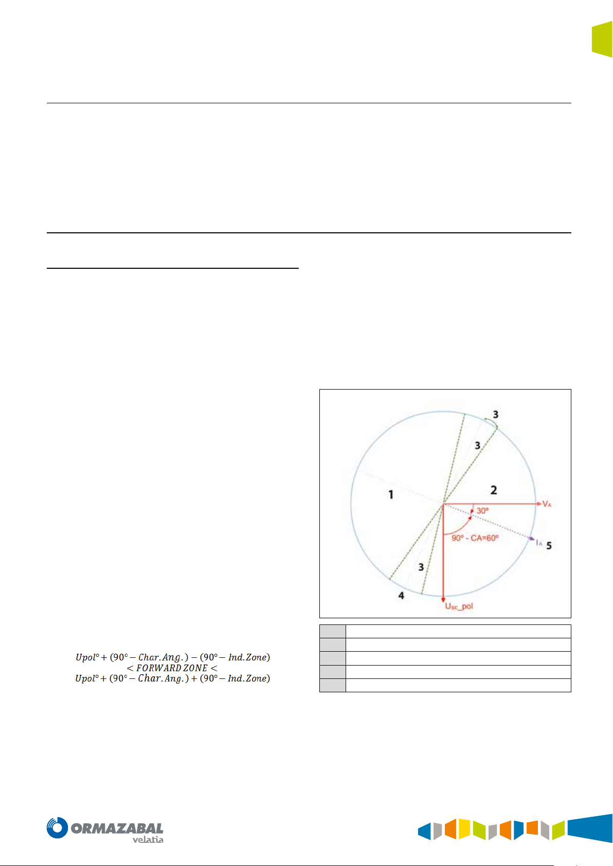
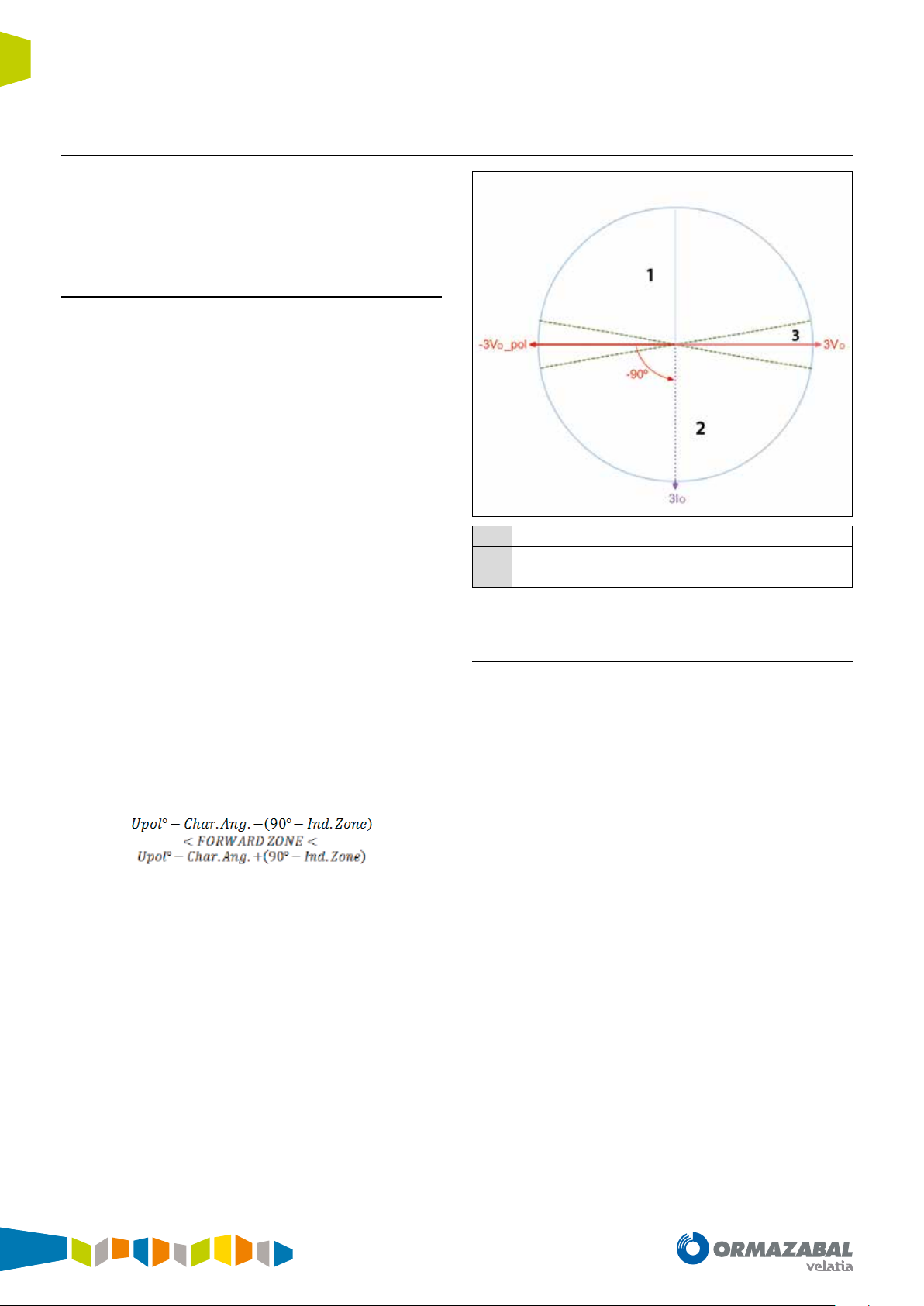
The figure shows an example of operation of the directional
unit of phase A:
• Characteristic phase angle: Characteristic angle
(from - 90.0° to 90.0°). This often corresponds to the
series impedance angle of the lines. Typical values in
distribution: 30° and 45°.
• Minimum phases voltage: Minimum polarisation
voltage (from 0.5 kV to 72.0 kV). Polarisation voltage
value as of which the directional unit considers the
angle reliable, and is capable of determining a direction.
• Indeterminate zone: Indeterminate zone angle (from
0.0° to 90.0°). Setting to establish the indetermination
zone which is close to the zero torque line.
The direction indicated by the units can be Forward, Reverse
or ndef (undefined).
The Forward direction zone is delimited by the following
formula:
Reserve
1
Forward
2
Indeterminate zone
3
Zero torque line
4
Maximum torque line
5
Figure 4.3. Phase A directional unit
IG-267-EN versión 01; 07/04/2017
23
Protection functions General Instructions
ekor.rpa
4.3.2. Neutral and sensitive neutral directional units
The neutral and sensitive neutral directional units include
two different criteria to determine direction: Directional
criterion and wattmetric criterion. The criterion is selected
through a setting in the unit itself.
Angular criterion
The angular criterion of the neutral and sensitive neutral
directional units is based on the phase difference between
the polarisation signal (-3V
(3Io).
The polarisation signal used is the 180° out-of-phase
residual voltage, i.e.- 3V
The settings for the neutral and sensitive neutral directional
unit, which apply to the angular criteria, are:
) and the residual current signal
o
.
o
• Characteristic neutral angle: Characteristic angle (from
- 90.0° to 90.0°). In distributions with earthed neutral,
this often corresponds to the earth impedance angle.
• Minimum neutral voltage: Minimum polarisation
voltage (from 0.5 kV to 72.0 kV). Polarisation voltage
value as of which the directional unit considers the
angle reliable, and is capable of determining a direction.
• Indeterminate zone: Indeterminate zone angle (from
0.0° to 90.0°). Setting to establish the indetermination
zone which is close to the zero torque line.
The direction indicated by the units can be Forward, Reverse
or ndef (undefined).
The Forward direction zone is delimited by the following
formula:
The Reverse direction zone will be the opposite of the
Forward zone. In other words, the above formula needs to
be turned around 180° in order to achieve the expression
which delimits the Reverse direction zone.
The directional units will indicate ndef direction if in the
indeterminate zone or polarisation voltage is below the V
min
setting.
The figure below shows an example of operation for the
neutral directional unit:
Reserve
1
Forward
2
Indeterminate zone
3
Figure 4.4. Neutral directional unit
Wattmetric criterion
The wattmetric criterion of the neutral and sensitive neutral
directional units is based on the phase difference between
the polarisation signal (- 3V
) and the residual current signal
o
(3lo), along with the magnitude of the residual active power.
The settings for the neutral and sensitive neutral directional
unit, which apply to the wattmetric criteria, are:
• Minimum neutral active power: Minimum residual
active power. Minimum residual active power value (in
absolute value), as of which direction other than ndef
(i.e. Forward or Reverse) can be considered. Variable
ranges in accordance with current transformers used.
• Minimum neutral voltage: Minimum polarisation
voltage (from 0.5 kV to 72.0 kV). Polarisation voltage
value as of which the directional unit considers the
angle reliable, and is capable of determining a direction.
• Indeterminate zone: Indeterminate zone angle (from
0.0° to 90.0°). Angle formed by the 90° axis and the line
which delimits the indeterminate zone.
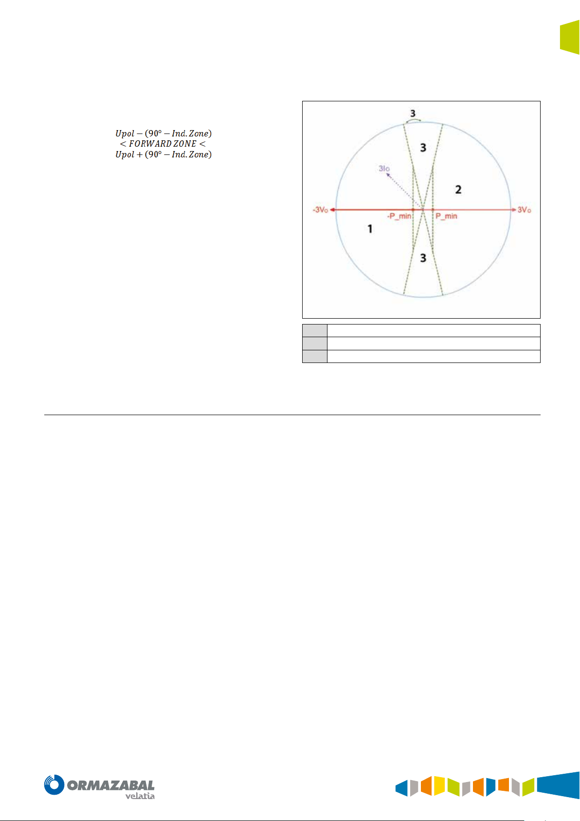
The direction indicated by the units can be Forward, Reverse
or ndef (undefined).
24
IG-267-EN versión 01; 07/04/2017
General Instructions
ekor.rpa
Protection functions
The unit will indicate Forward direction in the following
conditions:
• The residual current signal (3I
) drops in the following
o
zone:
The residual active power is lower than - P
min
.
The reverse direction zone will be the opposite of the
Forward zone. In other words, the above formula needs to
be turned around 180° in order to achieve the expression
which delimits the reverse direction zone. Furthermore,
residual active power must be greater than + P
min
.
The unit will give undefined direction if:
• The residual active power in absolute value is lower
than P
• The polarisation voltage value is lower than the V
min
.
min
setting.
• This is found in the indeterminate zone (see figure
below).
The figure below shows an example of operation for the
neutral directional unit with wattmetric criterion:
Reserve
1
Forward
2
Indeterminate zone
3
Figure 4.5. Neutral unit with wattmetric criterion
4.4. Thermal image unit
The ekor.rpa-100 model 120 systems are fitted with
the thermal image unit (49) for protection of lines and
transformers.
On certain occasions, the thermal overload of the element
to be protected cannot be detected by conventional
protection units. Furthermore, many of the elements
installed in the power system are being used ever-closer to
their thermal limits, making it necessary for the protection
devices used for these elements to have thermal units.
The thermal image unit is a unit which, in accordance with
the estimated thermal capacity value, generates alarm and
trip signals.
IG-267-EN versión 01; 07/04/2017
25
Protection functions General Instructions
ekor.rpa
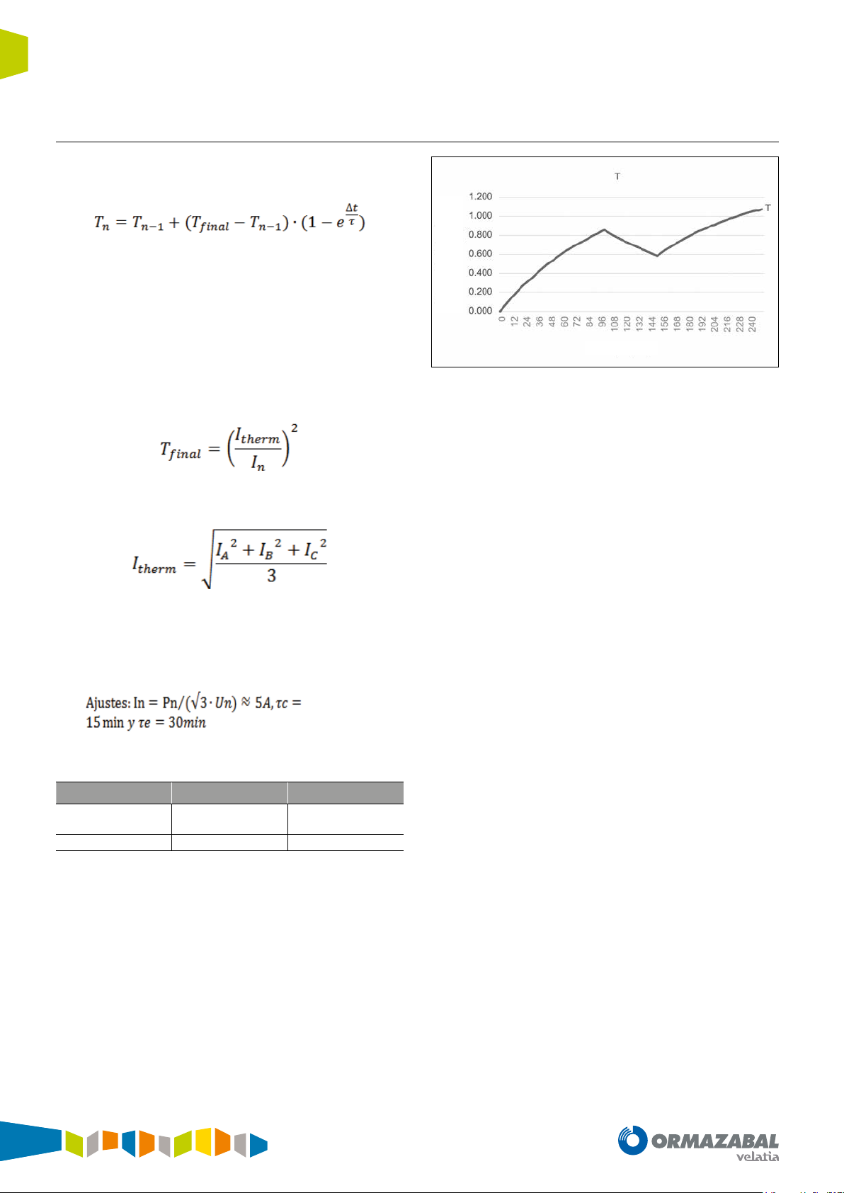
4.4.1. Estimated thermal capacity
The system estimates thermal capacity through the phase
currents (I
Where:
T
: Estimated thermal capacity at instant n
n
T
: Estimated thermal capacity at instant n-1
n-1
Δt: Time interval between consecutive n and n-1 instants
τ: Cooling or heating constant If T
constant will be applied in the formula If, on the other hand,
T
final
T
: Final thermal capacity This value is calculated based on the
final
, IB and IC), using the following formula:
A
< T
final
< T
, the cooling constant will be applied in the formula
n-1
, the temperature rise
n-1
adjusted rated current and the phase currents, in accordance
with the following formula:
capacity (T)
Estimated thermal
Time (min)
Figure 4.6. Estimated thermal capacity
Starting from an initial thermal capacity of 0 %, during the
first 100 min where current is 16 % higher than the rated
(5.8 A), estimated thermal capacity reaches a value of
84.6 %.
I
: The estimated mean thermal current based on the phase
therm
currents:
Example
The evolution of the thermal capacity estimated by the
system for a 250 kVA transformer in a 30 kV network
under the following conditions:
I
sequence read by the equipment:
therm
Interval 1 Interval 2 Interval 3
From 0 min
to 100 min
5.8 A 1.5 A 5.8 A
Table 4.1. I
read by the system
therm
From 100 min
to 150min
From 150 min
to 250min
In the next 50 min current drops to 30 % of rated current
(1.5 A), and this makes thermal capacity drop to 58.4 %.
A third interval identical to interval 1 has been chosen to
check the memory effect of the estimated thermal capacity.
In other words, a current which is 16 % higher than the rated
(5.8 A) for 100 min. It is observed that, after these 100 min,
thermal capacity reaches 106.3 %, thus exceeding 100 %
(typical trip level setting).
This difference in the estimated thermal capacity between
intervals 1 and 3 is due to the fact that previous statuses
are taken into account in the calculation. Hence, as the first
interval starts from a thermal capacity equal to 0 %, the third
interval starts from the thermal capacity accumulated up
to this moment, taking into account all the thermal stress
suffered by the element to be protected. This means the
estimated thermal capacities are different in these intervals.
26
IG-267-EN versión 01; 07/04/2017
General Instructions
ekor.rpa
4.4.2. Functionality
Protection functions
The thermal image unit starts up (with an alarm signal) if the
thermal capacity value exceeds the alarm level setting (%),
tripping whenever the trip level setting is exceeded (%).
Once the unit has tripped, this will reset when the thermal
capacity value drops below the trip reset level setting (%).
The settings for the thermal image unit are:
• Enabling the unit: Enable/disable the unit (ON/OFF).
• Temperature rise constant: Temperature rise constant
(from 3 min to 60 min).
• Cooling constant: Cooling constant (from 3 min to
180 min).
• Alarm level: Alarm threshold percentage. The thermal
capacity percentage from which an alarm situation is
considered (from 80 % to 100 %).
• Trip level: Trip threshold percentage. The thermal
capacity percentage from which a thermal overload is
tripped (from 100 % to 200 %).
• Trip reset level: Reset threshold. The thermal capacity
percentage below which the unit is reset (from 50 % to
99 %).
• Rated current: Rated current of the element to be
protected. Variable ranges in accordance with current
transformers used.
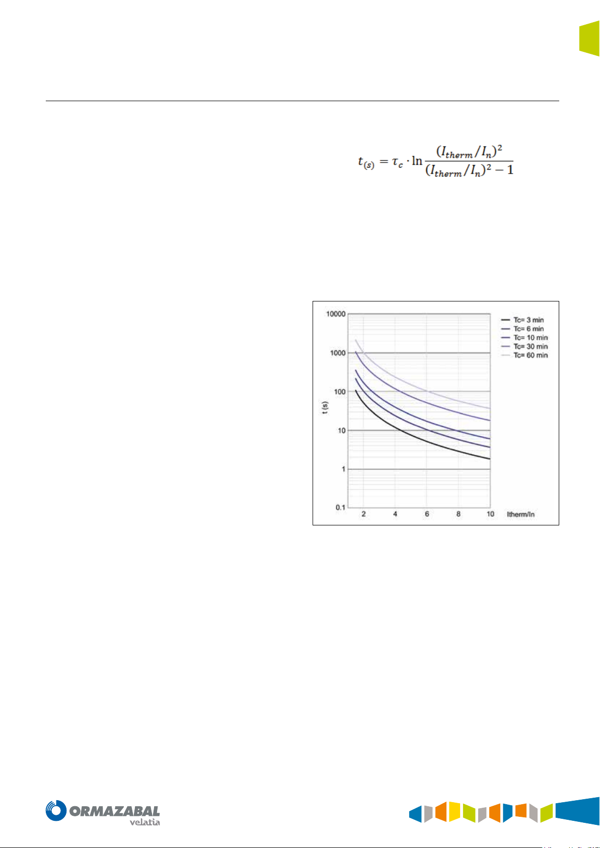
The time taken to reach tripping, based on a thermal
capacity equal to zero, given by the following formula:
Where:
t: Tripping time
τ
: Temperature rise constant
c
I
: Adjusted rated current
n
I
: The estimated mean thermal current based on the phase
therm
currents
The trip times for different temperature rise constants are
shown graphically below:
Figure 4.7. Trip time
IG-267-EN versión 01; 07/04/2017
27
Protection functions General Instructions
ekor.rpa
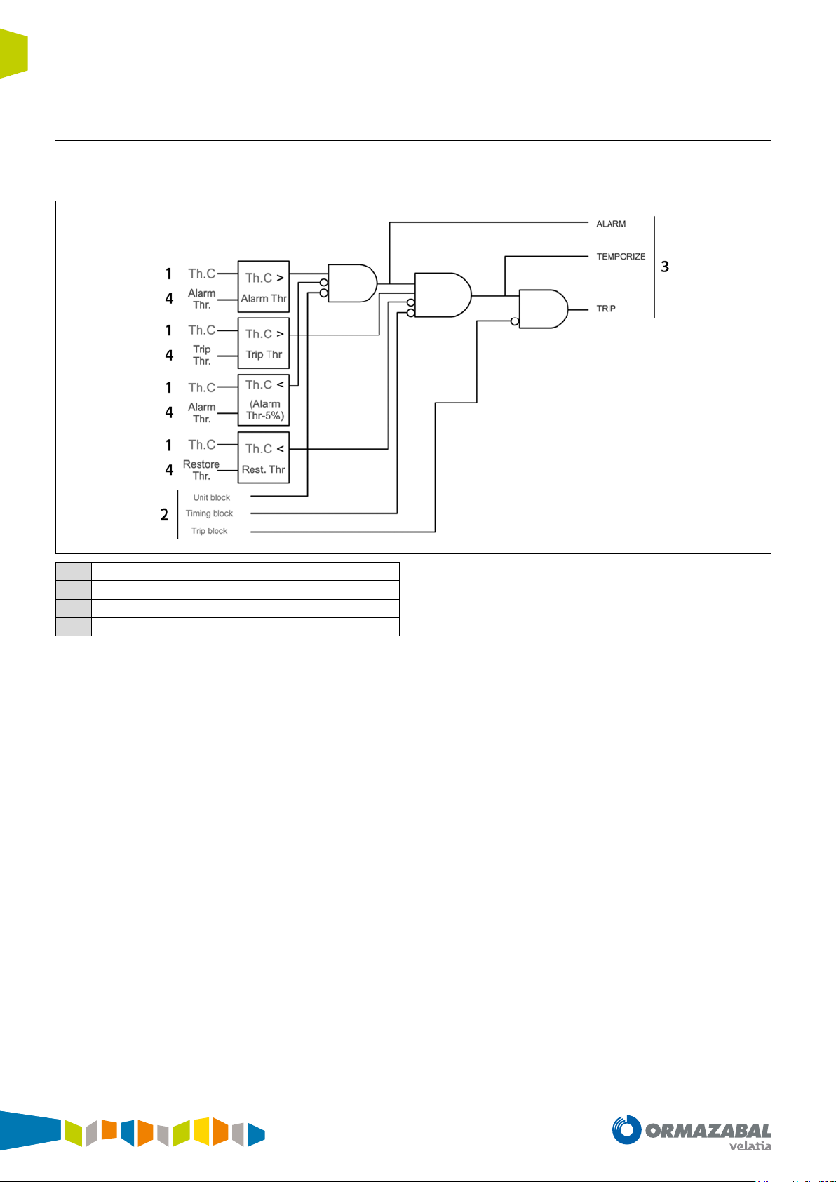
4.4.3. Block diagram
The thermal image unit complies with the following block
diagram :
Metering
1
Input signal
2
Output signal
3
Settings
4
Figure 4.8. Block diagram
The thermal image unit generates the following signal:
• Alarm: Activated when the estimated magnitude of
thermal capacity (Th. C) exceeds the “Alarm Threshold”
setting, and is disabled when estimated thermal capacity
(Th. C) drops below the “Alarm Threshold – 5%” setting.
• Temporize: Activated when the estimated magnitude
of thermal capacity (Th. C) exceeds the “Trip Threshold”
setting, and is disabled when estimated thermal capacity
(Th. C) drops below the “Restore Threshold” setting.
• Trip: Activated when the temporize signal is activated,
and disabled when the estimated thermal capacity (Th.
C) drops below the “Restore Threshold” setting.
Moreover, the thermal image unit can be blocked by the
maximum current blocking unit detailed in the following
sections.
The thermal image unit can be blocked in three different
ways:
• Unit Block: Blocks the unit, preventing start-up while
this input remains active.
• Timing Block: Blocks the unit, allowing it to run the
alarm signal but not allowing the temporize or trip signal.
• Trip Block: Allows the unit to advance, and blocks it
before the trip output.
28
IG-267-EN versión 01; 07/04/2017
General Instructions
ekor.rpa
4.5. Broken conductor unit
Protection functions
The ekor.rpa-100 model 120 systems are fitted with the
broken conductor unit (46BC).
Conventional protection functions cannot detect conditions
in which one of the conductors is broken.
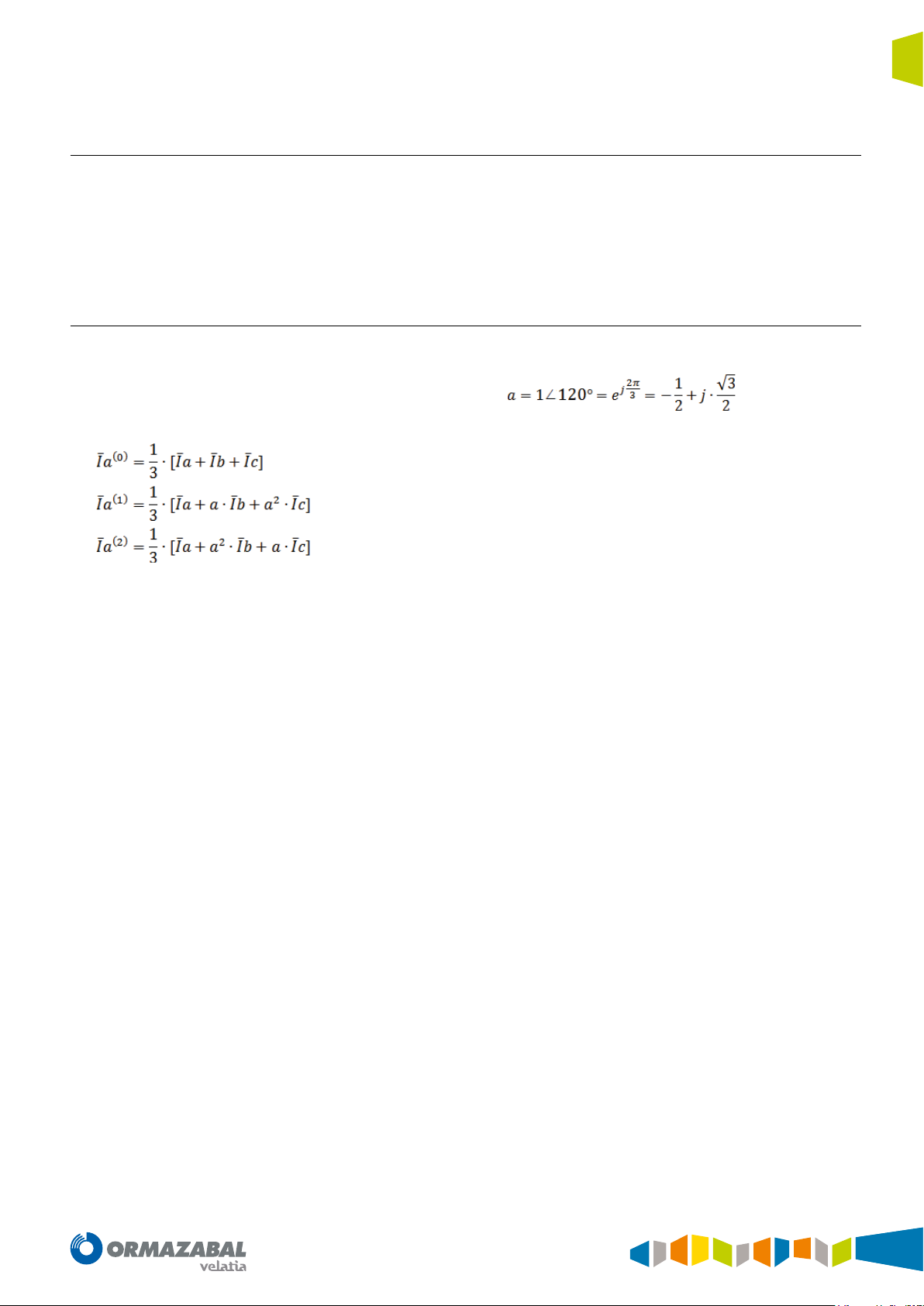
4.5.1. Calculation of sequence currents
The broken conductor unit is supplied by the sequence
currents (I
, I2 and Io) previously calculated by the system.
1
The sequence current calculation is carried out in
accordance with these formulae:
The broken conductor unit (46 Broken Conductor) can
be used to detect broken conductors, by monitoring
the sequence currents, and another series of conditions
detailed in this section.
Where,
With the phase A sequence components known, the B
and C sequence components will be identical in modules,
displaced 120° in angle in the case of direct and inverse
sequence, and with the same angle in the case of zerosequence.
IG-267-EN versión 01; 07/04/2017
29
Protection functions General Instructions
ekor.rpa
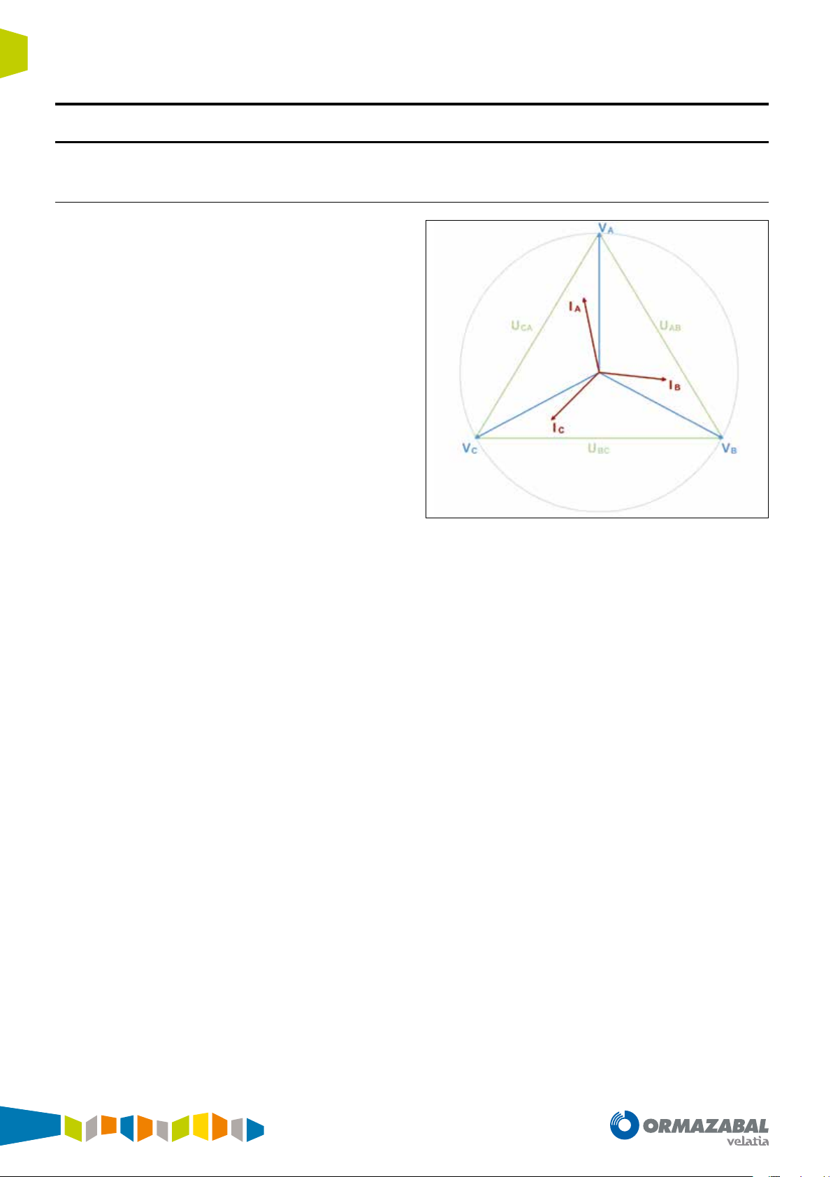
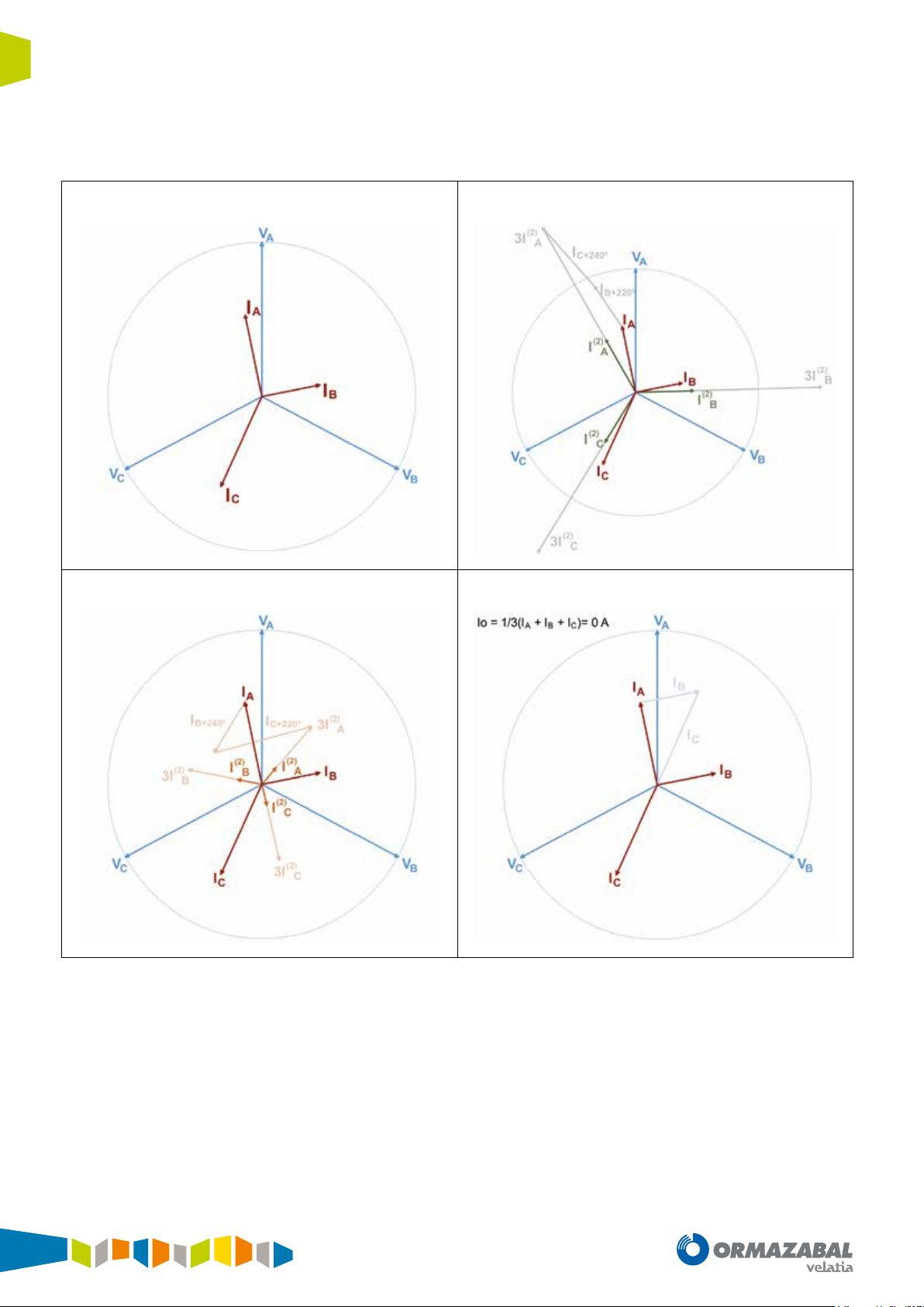
The following image shows an example of calculation of the
sequences based on an imbalanced system. It is observed
that the system has a large inverse component, but no zero-
Line currents Direct-sequence currents
sequence (situation which can come about in lines which
are not uniformly charged in the three phases):
Inverse-sequence currents Zero-sequence currents
Figure 4.9. Calculation of sequences
30
IG-267-EN versión 01; 07/04/2017
 Loading...