

Ormazabal cgm.3-l, cgm.3-p, cgm.3-s, cgm.3-s-pt, cgm.3-pti General Instructions Manual
...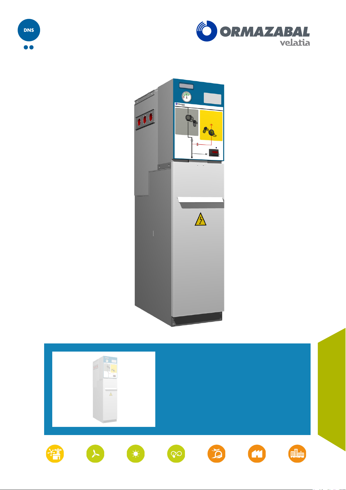
cgm.3 system
Fully SF6 gas insulated medium
voltage switchgear up to 40.5 kV in
accordance with IEC Standards
General instructions
IG-136-EN, version 10; 23/06/2016

CAUTION!
When medium-voltage equipment is operating, certain components are live, other parts may be in movement and some may reach high
temperatures. Therefore, the use of this equipment poses electrical, mechanical and thermal risks.
In order to ensure an acceptable level of protection for people and property, and in compliance with applicable environmental
recommendations, Ormazabal designs and manufactures its products according to the principle of integrated safety, based on the
following criteria:
• Elimination of hazards wherever possible.
• Where elimination of hazards is neither technically nor economically feasible, appropriate protection functions are
incorporated in the equipment.
• Communication about remaining risks to facilitate the design of operating procedures which prevent such risks, training
for the personnel in charge of the equipment, and the use of suitable personal protective equipment.
• Use of recyclable materials and establishment of procedures for the disposal of equipment and components so that
once the end of their service lives is reached, they are duly processed in accordance, as far as possible, with the
environmental restrictions established by the competent authorities.
Consequently, the equipment to which the present manual refers complies with the requirements of section 11.2 of Standard IEC 62271-
1. It must therefore only be operated by appropriately qualified and supervised personnel, in accordance with the requirements of
standard EN 50110-1 on the safety of electrical installations and standard EN 50110-2 on activities in or near electrical installations.
Personnel must be fully familiar with the instructions and warnings contained in this manual and in other recommendations of a more
general nature which are applicable to the situation according to current legislation
The above must be carefully observed, as the correct and safe operation of this equipment depends not only on its design but also on
general circumstances which are in general beyond the control and responsibility of the manufacturer. More specifically:
[1].
• The equipment must be handled and transported appropriately from the factory to the place of installation.
• All intermediate storage should occur in conditions which do not alter or damage the characteristics of the equipment or
its essential components.
• Service conditions must be compatible with the equipment rating.
• The equipment must be operated strictly in accordance with the instructions given in the manual, and the applicable
operating and safety principles must be clearly understood.
• Maintenance should be performed properly, taking into account the actual service and environmental conditions in the
place of installation.
The manufacturer declines all liability for any significant indirect damages resulting from violation of the guarantee, under any jurisdiction,
including loss of income, stoppages and costs resulting from repair or replacement of parts.
Warranty
The manufacturer guarantees this product against any defect in materials and operation during the contractual period. If defects are
detected, the manufacturer may opt either to repair or replace the equipment. Improper handling of this equipment and its repair by the
user shall constitute a violation of the guarantee.
Registered trademarks and copyrights
All registered trademarks cited in this document are the property of their respective owners. The intellectual property of this manual
belongs to Ormazabal.
[1]
For example, in Spain the “Regulation on technical conditions and guarantees for safety in high-voltage electrical installations” –
Royal Decree 337/2014 is obligatory.
In view of the constant evolution in standards and design, the characteristics of the elements contained in this manual are subject
to change without prior notice. These characteristics, as well as the availability of components, are subject to confirmation by
Ormazabal.

General instructions
cgm.3 system
Fully SF6 gas insulated medium voltage switchgear up to 40.5 kV in accordance with IEC Standards
Contents
1 General description ......................................................... 6
1.1 Models .................................................................................6
1.2 Standards applied........................................................................7
1.3 Main components ........................................................................7
1.3.1 Gas tank .........................................................................8
1.3.2 Driving mechanism compartment ......................................................8
1.3.3 Base.............................................................................9
1.3.4 Name plate ......................................................................10
1.4 Characteristics table.....................................................................11
1.5 Dimensions and weights .................................................................12
1.6 Operating conditions ....................................................................13
3
2 Handling and transport ..................................................... 14
2.1 Lifting means...........................................................................14
3 Storage .................................................................. 16
4 Installation ............................................................... 17
4.1 Unpacking the equipment ................................................................17
4.2 Location of accessories during transport ...................................................17
4.3 Minimum installation distances............................................................18
4.4 Recommended cable connection trench ....................................................19
4.4.1 Cubicles with internal arc in gas tank up to 20 kA - 0.5 s ...................................19
4.4.2 Cubicles with classification of internal arc IAC up to 25 kA - 1 s ..............................22
4.5 Fastening to the floor ....................................................................26
4.5.1 Fastening to the floor on profile .......................................................26
4.5.2 Fastening to the floor by anchoring ....................................................26
4.6 Connecting the cubicles .................................................................29
4.7 Earthing the switchgear ..................................................................29
4.8 Cable connections ......................................................................30
4.8.1 Horizontal front connection ..........................................................30
4.8.2 Cable connection in fuse protection function 1400 mm high .................................31
4.9 Assembly and connection of measuring transformers in cgm.3-m ...............................33
IG-136-EN version 10; 23/06/2016

4
General instructions
cgm.3 system
Fully SF6 gas insulated medium voltage switchgear up to 40.5 kV in accordance with IEC Standards
5 Recommended sequence of operations ....................................... 34
5.1 Checking the gas pressure ...............................................................34
5.2 Voltage presence indicator ...............................................................34
5.3 Phase balance check ....................................................................35
5.4 Feeder function .........................................................................36
5.4.1 Mimic diagram ....................................................................36
5.4.2 Driving levers .....................................................................37
5.4.3 Opening operation from earthing position ...............................................37
5.4.4 Switch closing operation from the disconnected position ...................................38
5.4.5 Opening operation from closed position ................................................39
5.4.6 Earthing operation from the disconnected position ........................................40
5.4.7 Cable test........................................................................40
5.5 Busbar switch function ..................................................................41
5.5.1 Mimic diagram ....................................................................41
5.5.2 Driving lever......................................................................41
5.5.3 Switch closing operation from the disconnected position ...................................42
5.5.4 Opening operation from closed position ................................................43
5.6 Busbar switch function with earth connection ...............................................44
5.6.1 Mimic diagram ....................................................................44
5.6.2 Driving lever......................................................................44
5.6.3 Opening operation from earthing position ...............................................45
5.6.4 Connection of the switch-disconnector from the disconnected position ........................46
5.6.5 Opening operation from closed position ................................................46
5.6.6 Earthing operation from open position..................................................47
5.7 Busbar rise function with earth connection..................................................48
5.7.1 Mimic diagram ....................................................................48
5.7.2 Driving levers .....................................................................48
5.7.3 Earthing switch disconnection ........................................................49
5.7.4 Earthing switch connection ..........................................................49
5.8 Fuse protection function .................................................................51
5.8.1 Mimic diagram ....................................................................51
5.8.2 Driving lever......................................................................51
5.8.3 Opening operation from earthing position ...............................................52
5.8.4 Spring charge operation and closing of the switch - disconnector from disconnected position.......52
5.8.5 Opening operation from the switch-disconnector closed position .............................53
5.8.6 Earthing operation from the open position...............................................54
5.9 Fuse replacement sequence ..............................................................54
5.9.1 Selection of recommended fuses .....................................................57
IG-136-EN version 10; 23/06/2016

General instructions
cgm.3 system
Fully SF6 gas insulated medium voltage switchgear up to 40.5 kV in accordance with IEC Standards
5.10 Circuit-breaker function with AV / RAV driving mechanism ....................................58
5.10.1 Mimic diagram ...................................................................58
5.10.2 Spring charge and driving levers .....................................................58
5.10.3 Opening operation from earthing position ..............................................59
5.10.4 Closing operation from open position .................................................60
5.10.5 Opening operation from closed position ...............................................61
5.10.6 Earthing Operation from the open position .............................................62
6 Safety elements ........................................................... 64
6.1 Acoustic earthing prevention alarm ........................................................64
6.2 Interlocks ..............................................................................64
6.2.1 Locking with a padlock..............................................................65
6.2.2 Locking with a lock.................................................................65
5
7 Maintenance .............................................................. 66
7.1 Voltage presence indicator test ............................................................66
7.2 Acoustic earthing prevention alarm test ....................................................67
7.3 Specific maintenance for the cgm.3-v cubicle ...............................................68
8 Spares and accessories .................................................... 69
9 Environmental information .................................................. 71
IG-136-EN version 10; 23/06/2016
General description
6
1 General description
General Instructions
cgm.3 system
Fully SF6 gas insulated medium voltage switchgear up to 40.5 kV in accordance with IEC Standards
The cgm.3 system by Ormazabal, designed following the
requirements indicated by regulations of the International
Electrotechnical Commission (IEC), is made up of different
unifunctional and multifunctional switchgear models,
with full SF6 gas insulation, which can be used to configure
different secondary distribution configurations in medium
voltage up to 40.5 kV
1.1 Models
Unifunctional switchgear Function
cgm.3-l
cgm.3-s
cgm.3-s-pt
cgm.3-p
cgm.3-v
cgm.3-rb
Feeder
Busbar switch
Busbar switch with earth connection on the right (-ptd) or on the
left (-pti)
Fuse protection
Vacuum circuit-breaker
Busbar rise
[1]
.
cgm.3-rc / -r2c
cgm.3-m
Cable/double cable rise
Metering
Multifunctional switchgear Functions
cgm.3-2lp
cgm.3-2lv
[1] Further information at www.ormazabal.com.
2 feeder functions and 1 fuse protection
2 feeder functions and 1 vacuum circuit-breaker
IG-136-EN version 10; 23/06/2016
General Instructions
General description
cgm.3 system
Fully SF6 gas insulated medium voltage switchgear up to 40.5 kV in accordance with IEC Standards
1.2 Standards applied
Standard Description
IEC 62271-1 Common specifications for high-voltage switchgear and controlgear standards.
IEC 62271-100 High-voltage alternating current circuit-breakers.
IEC 62271-102 Alternating current disconnectors and earthing switches.
IEC 62271-103 High-voltage switches for rated voltages above 1 kV up to and including 52 kV.
IEC 62271-105 Alternating current switch-fuse combinations.
7
IEC 62271-200
Alternating current metal-enclosed switchgear and controlgear for rated
voltages above 1 kV and up to and including 52 kV.
IEC 62271-206 / IEC 61243-5 Voltage presence indicating systems.
IEC 60529 Protection grades for enclosures.
IEC 60282-1 Current-limiting fuses.
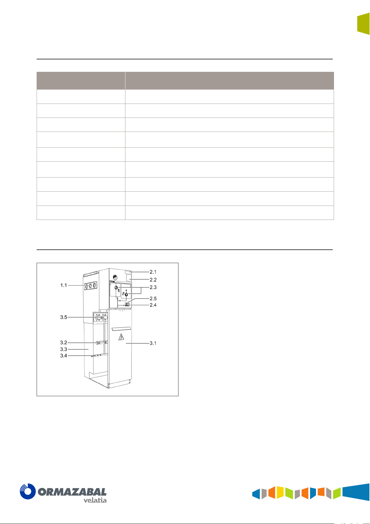
1.3 Main components
1. Gas tank
1.1. Side connection female bushings
2. Driving mechanism area
2.1.Name plate
2.2.Operating sequence plate
2.3. Driving shafts (see mimic diagram of each model).
2.4. ekor.vpis / ekor.ivds* Voltage presence detection unit
2.5. ekor.sas* acoustic earthing prevention alarm unit.
3. Base
3.1 Cable compartment access cover
3.2 Medium-voltage cable fastening support
3.3.Gas relief compartment
3.4.Earth collector
3.5 Front cable connection bushings
* Optional elements.
Figure 1.1 Main elements of cgm.3 cubicles
IG-136-EN version 10; 23/06/2016
General description
8
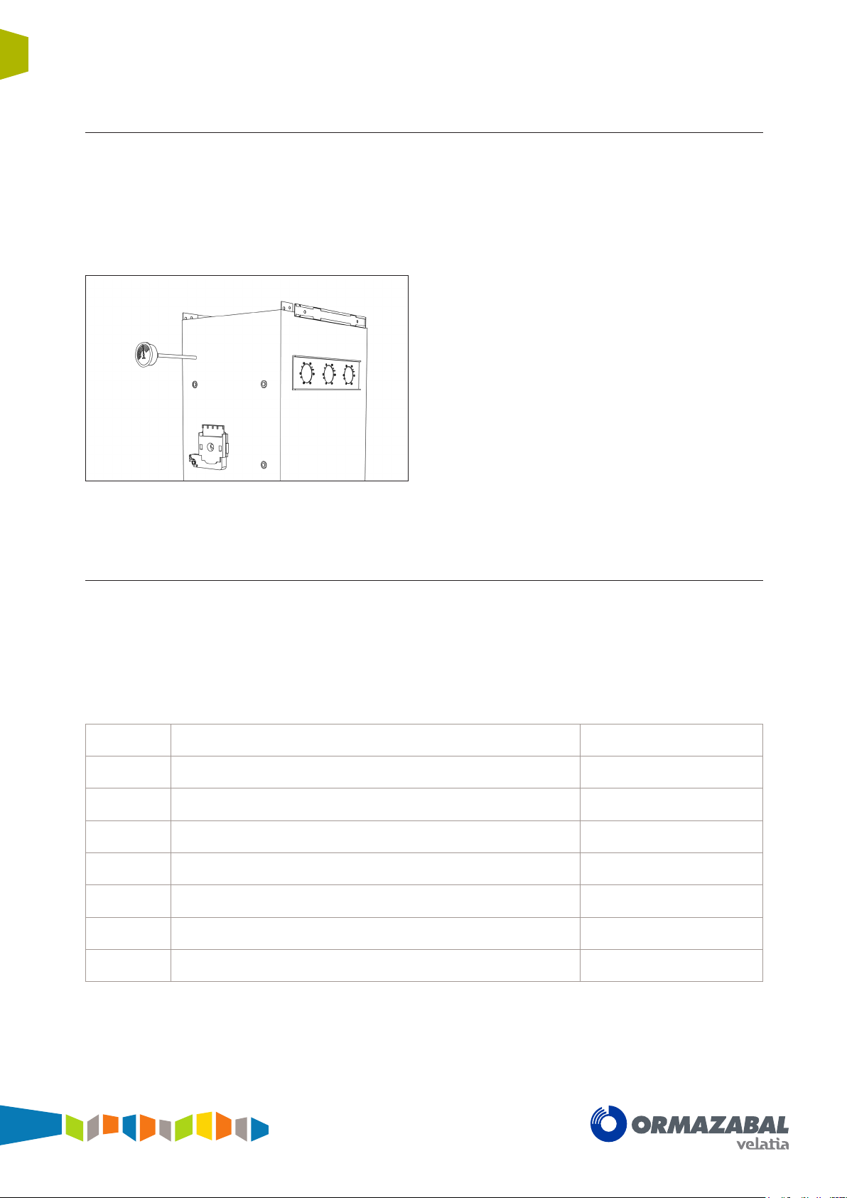
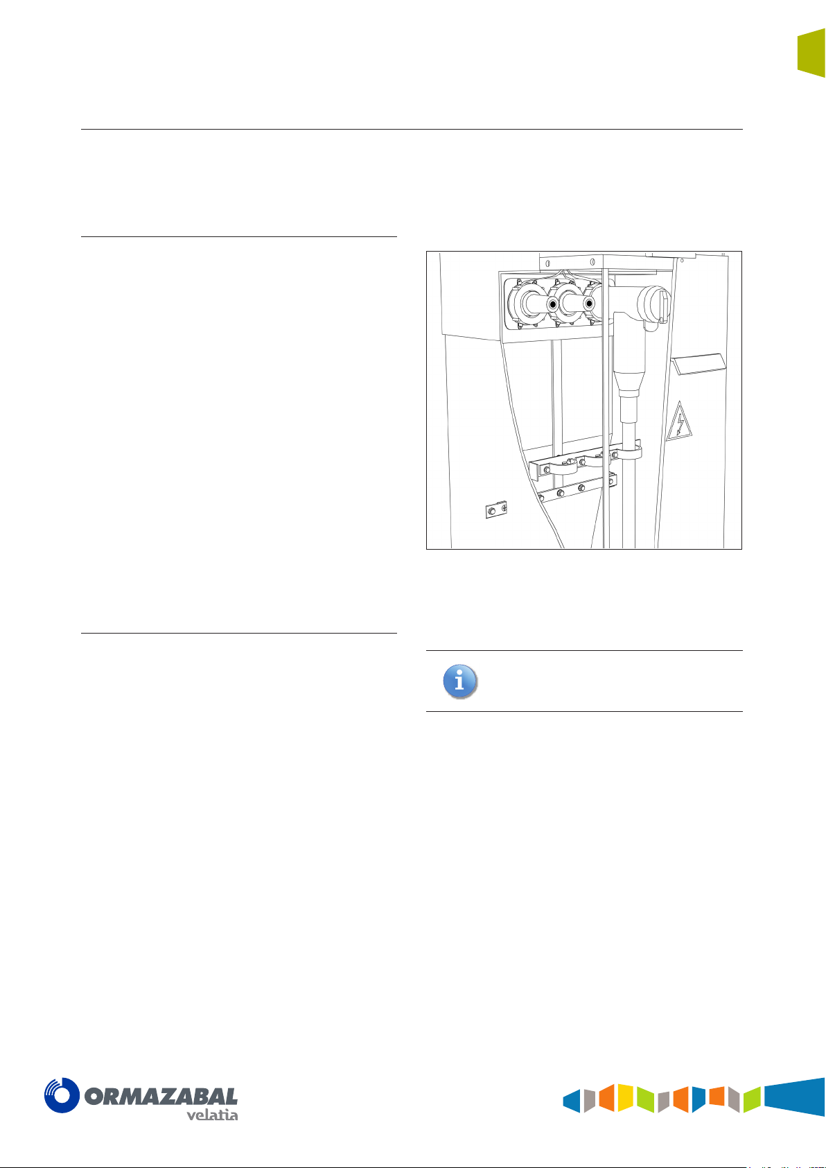
1.3.1 Gas tank
General Instructions
cgm.3 system
Fully SF6 gas insulated medium voltage switchgear up to 40.5 kV in accordance with IEC Standards
Sealed compartment which houses the busbar and the
switching and breaking elements, where the insulating
medium is SF6.
Each gas tank has a pressure relief device to facilitate gas
relief in the event of internal arc.
Figure 1.2 Gas tank for cgm.3-l
1.3.2 Driving mechanism compartment
Thanks to the hermetically-sealed nature of the gas
tank containing all the medium voltage elements, the
equipment is expected to have a minimum service life of
30 years, without replenishing the gas, in accordance with
Standard IEC 62271-1.
This is the compartment in which the switch-disconnector,
earthing switch or circuit-breaker is driven, depending on
the type of function.
The mimic diagram for the main medium voltage circuit is
displayed on the cover of this compartment.
B
BM Motorised tilting
BR-A Accumulation of energy with latch
BR-AM Accumulation of energy with motorised latch
AV Circuit-breaker without reclosing
AMV Motorised circuit-breaker without reclosing
RAV Circuit-breaker with reclosing option
RAMV Motorised circuit-breaker with reclosing option
These elements are operated independently, i.e., their
actuation speed does not depend on the speed of the
manual operation.
The B, BM, BR, AR and BR-AM driving mechanisms can
be replaced by upgrading in any of the three possible
Tilting
The mimic diagram includes all the position indicators for
the driving elements.
The cgm.3 system has, in line with the cubicle model, the
following types of driving mechanism:
l, s, s-pt, rb-pt, v, 2lp, 2lv
l, s, s-pt, 2lp, 2lv
p, 2lp
l, p, 2lp
v, 2lv
v, 2lv
v, 2lv
v, 2lv
positions (closed – opened – earth). Whilst the driving
mechanism is withdrawn, these positions of the switch can
be blocked using a coupling device, whether in service or
not.
IG-136-EN version 10; 23/06/2016
General Instructions
General description
cgm.3 system
Fully SF6 gas insulated medium voltage switchgear up to 40.5 kV in accordance with IEC Standards
1.3.3 Base
Made up of the cable compartment and the gas relief
compartment:
Cable compartment
This is located in the lower front section of the cubicle
and has a cover interlocked with the earthing switch, thus
allowing front access to the medium voltage cables.
As standard, designed to contain up to:
• Two shielded screw-in terminals (reduced)
per phase or one terminal (reduced) plus
surge arrester (reduced) with space for the
corresponding incoming power cables.
• Cable ties for the power cables.
• Earthing bars.
As an option:
9
• Two symmetric terminals or symmetric terminal
plus symmetric surge arrester.
• Metallic voltage transformers.
Gas relief compartment
The cgm.3 system by Ormazabal is designed and
constructed to withstand at least the thermal and dynamic
effects of an arc of 16 kA for 0.5 seconds should a defect
result in an internal arc in the gas compartment. The
system conducts the gases generated in a fully controlled
manner to avoid any possible injury to people in the
equipment operation area.
Figure 1.3 Cable compartment
Optionally, a chimney can be positioned in the
rear of the cubicle to redirect the gases to the
top section. Please check with Ormazabal.
IG-136-EN version 10; 23/06/2016
10
General description
Fully SF6 gas insulated medium voltage switchgear up to 40.5 kV in accordance with IEC Standards
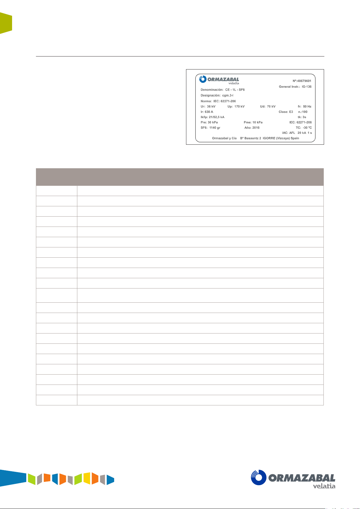
1.3.4 Name plate
Every unit includes a name plate, with some of the
following data:
Name plate
General Instructions
cgm.3 system
Figure 1.4 Example of name plate
Nº Cubicle serial number
(*)
Type Cubicle system Ormazabal
Designation Cubicle model
Standard Standards applied to the equipment
Name Equipment name
U
r
U
p
U
d
f
r
I
r
Instructions
Manual
Equipment rated voltage (kV)
Lightning impulse withstand voltage (kV)
Industrial frequency withstand voltage (kV)
Equipment rated frequency (Hz)
Equipment rated current (A)
General Instructions Manual (IG) for the system
Class Driving mechanism class according to IEC 62271-103
N Number of mainly active load breaking operations
/ I
I
k
t
k
P
re
P
me
SF
Year
TC
IAC
p
6
Short-time withstand current/Short-time withstand peak value
Short-time withstand current time
Gas pressure inside the tank (MPa)
Minimum operating gas pressure (MPa)
Weight of insulating fluid (g)
Year of manufacture
Minimum working temperature
Classification of internal arc
(*)
In the event of incident, this number should be reported to Ormazabal.
IG-136-EN version 10; 23/06/2016
General Instructions
General description
cgm.3 system
Fully SF6 gas insulated medium voltage switchgear up to 40.5 kV in accordance with IEC Standards
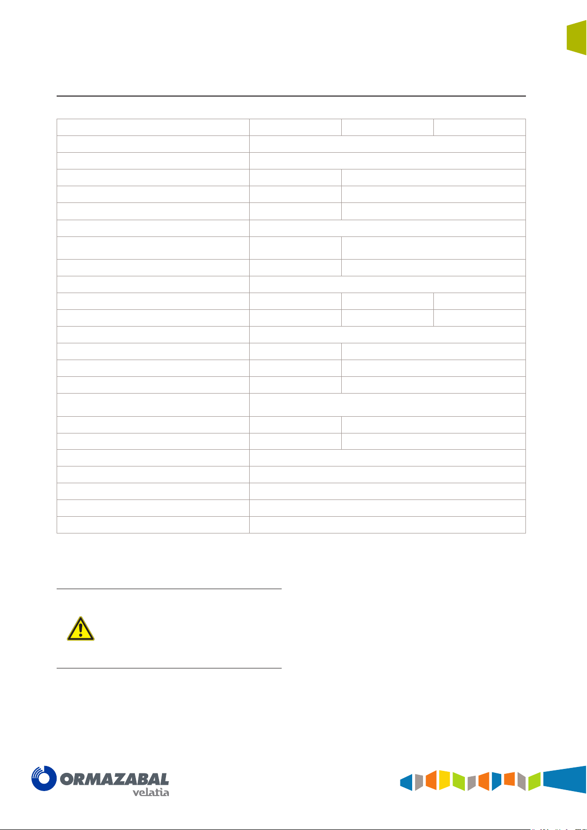
1.4 Characteristics table
Rated voltage [kV] 36 38.5 40.5
Frequency [Hz] 50 / 60
Rated current [A]
Busbars and cubicle interconnection 400 / 630 630
Feeder 400 / 630 630
Output to transformer 200 200
Rated short-term withstand current [kA]
= (x) s
With t
k
Peak value 40 / 52* / 62.5 52* / 62.5
Rated insulation level [kV]
Industrial frequency rated withstand voltage (1 min) 70 / 80 80 / 90 95 / 118
16 / 20* (1 / 3 s)
25 (1 s)
20* (1 / 3 s)
25 (1 s)
11
Lightning impulse rated withstand voltage 170 / 195 180 / 210 185 / 215
Internal arc in tank
Front accessibility 16 / 20* kA (0.5 s) 20* kA (0.5 s)
Front and side accessibility 16 / 20* / 25 kA (1 s) 20* / 25 kA (1 s)
Front, side and rear accessibility*** 16 / 20* / 25 kA (1 s) 20* / 25 kA (1 s)
Internal arc classification in accordance with
IEC 62271-200
IAC AF/AFL
IAC AFLR
Protection grade: Gas tank IP X8
Protection grade: External enclosure IP 2XD
Standard unit colour [RAL] grey 7035 / blue 5005
Category of loss of service continuity [LSC] LSC2
Compartmenting class PM
(*) Tests conducted with current 21 kA/54.6 kA
(**) With gas exhaust upwards via the chimney
The values set out in this table are general
for the cgm.3 system and are only valid once
conrmed by Ormazabal. Some cubicle
models can withstand partial values. For more
detailed information, check the table for each
cubicle model in the CA-112 catalogue by
Ormazabal.
16 / 20* / 25 kA (1 s) 20* / 25 kA (1 s)
16 / 20* / 25 kA (1 s) 20* / 25 kA 1 s
IG-136-EN version 10; 23/06/2016
12
General description
Fully SF6 gas insulated medium voltage switchgear up to 40.5 kV in accordance with IEC Standards
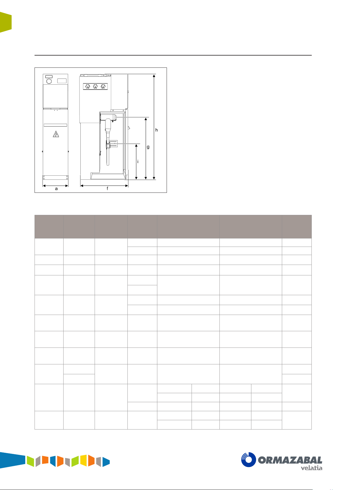
1.5 Dimensions and weights
General Instructions
cgm.3 system
Figure 1.5 Dimensions cgm.3
Cubicle
-l
-s
-s-pt
-p
-v
-rci
-rcd
-r2c
-rb
-rb-pt
Width (a)
[mm]
418 850
418 850 1745 - - 143
600 850 1745 - - 185
480 1010
[2]
600
367 831 1745 1590 1087 42
550 831 1745 1590 1087 65
418 850
1100
-m
900 300
-2lp
-2lv
1316 1010
1436 850 1745
Depth (f)
[mm]
[1]
850
[1]
1160 1950 - -
[1]
Height
(h) [mm]
1400 697 234 147
1745 1042 580 162
1400
1745
1400 350 20 240
1745 695 282 255
1745 1042 580 158
1400
1745 1042 525 580 234 490
Bushings height (g)
[mm]
180 - 128 215
-l -p -l -p
697 180 234 - 128
Cable fastening
-l -v -l -v
1042 695 580 282
height (l)
[mm]
Weight
[kg]
258
460
547
[1]
In the case of double symmetrical terminal, the Switchgear is an extra 80 mm deep.
[2]
As an option, there is also available a 595 mm wide model of the cgm.3-v cubicle. Please check with Ormazabal.
IG-136-EN version 10; 23/06/2016

General Instructions
General description
cgm.3 system
Fully SF6 gas insulated medium voltage switchgear up to 40.5 kV in accordance with IEC Standards
1.6 Operating conditions
Installation Indoor
Maximum ambient temperature + 40 ºC
Minimum ambient temperature – 5 ºC / - 30 ºC
Maximum mean ambient temperature, measured over a 24-hour period + 35 ºC
Maximum mean relative humidity, measured over a 24-hour period < 95%
Maximum mean relative humidity, measured over a 1-month period < 90%
Maximum mean vapour pressure, measured over a 24-hour period 2.2 kPa
Maximum mean vapour pressure, measured over a 1-month period 1.8 kPa
Maximum height above sea level 2000 m
13
(a)
Solar radiation Negligible
Ambient air pollution (dust, smoke, corrosive and/or flammable gases, vapours or
salt)
Vibrations caused by causes external to the switchgear or by seismic movements
(a)
1000 m for metering function and non-shielded connectors. For higher installation altitudes, check with Ormazabal.
(b)
Unless indicated otherwise, It is assumed that there are no specific user requirements.
The specications refer to the section "Normal
service conditions for indoor cubicles" in
Standard IEC 62271-1 "Common specications
for high-voltage cubicles".
For special service conditions: ambient
temperature above + 40 ºC, installation over
2000 m above sea level, signicant pollution
level, or others different to those described,
check with Ormazabal.
Insignificant
Insignificant
(b)
IG-136-EN version 10; 23/06/2016
14
Handling and transport
Fully SF6 gas insulated medium voltage switchgear up to 40.5 kV in accordance with IEC Standards
2 Handling and transport
Important: During transport, the switchgear
must be perfectly seated and xed so that it
cannot move about and possibly damage the
equipment.
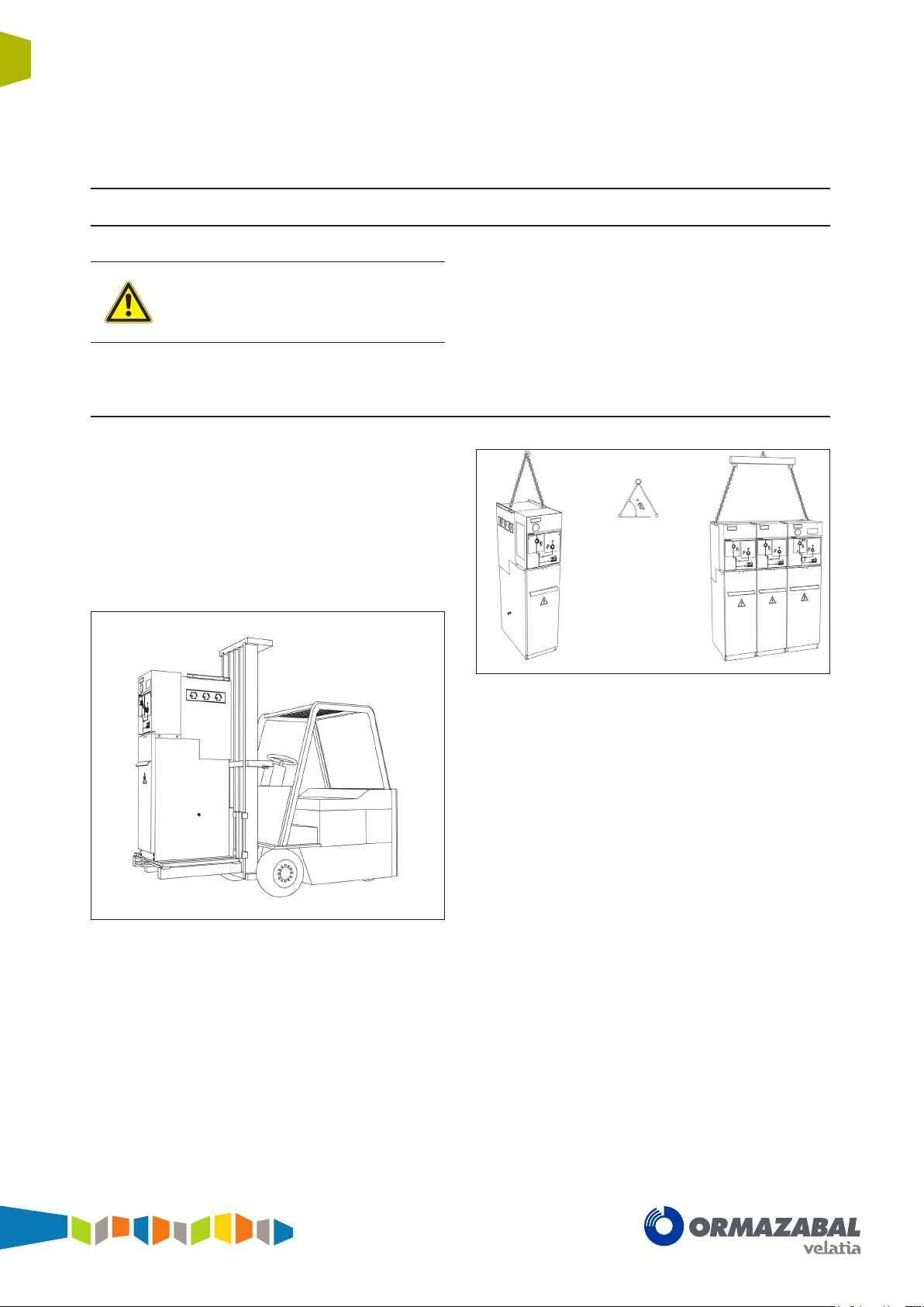
2.1 Lifting means
The switchgear must always be kept upright, directly
on the ground or on a pallet depending on the type of
handling involved.
General instructions
cgm.3 system
To handle assemblies of up to 4 cgm.3 functional units,
one of the following methods must be used:
[5]
1. Using a forklift truck or pallet-jack
Figure 2.1 Lifting a cgm.3 modular cubicle using a fork-lift
truck.
.
Figure 2.2 Lifting a cgm.3 modular cubicle with chains.
3. If it is not possible to use the aforementioned methods,
rollers may be used underneath the switchgear.
Another option is to slide the cubicles over rods
(these same rods can be used to help get over the
cable trench).
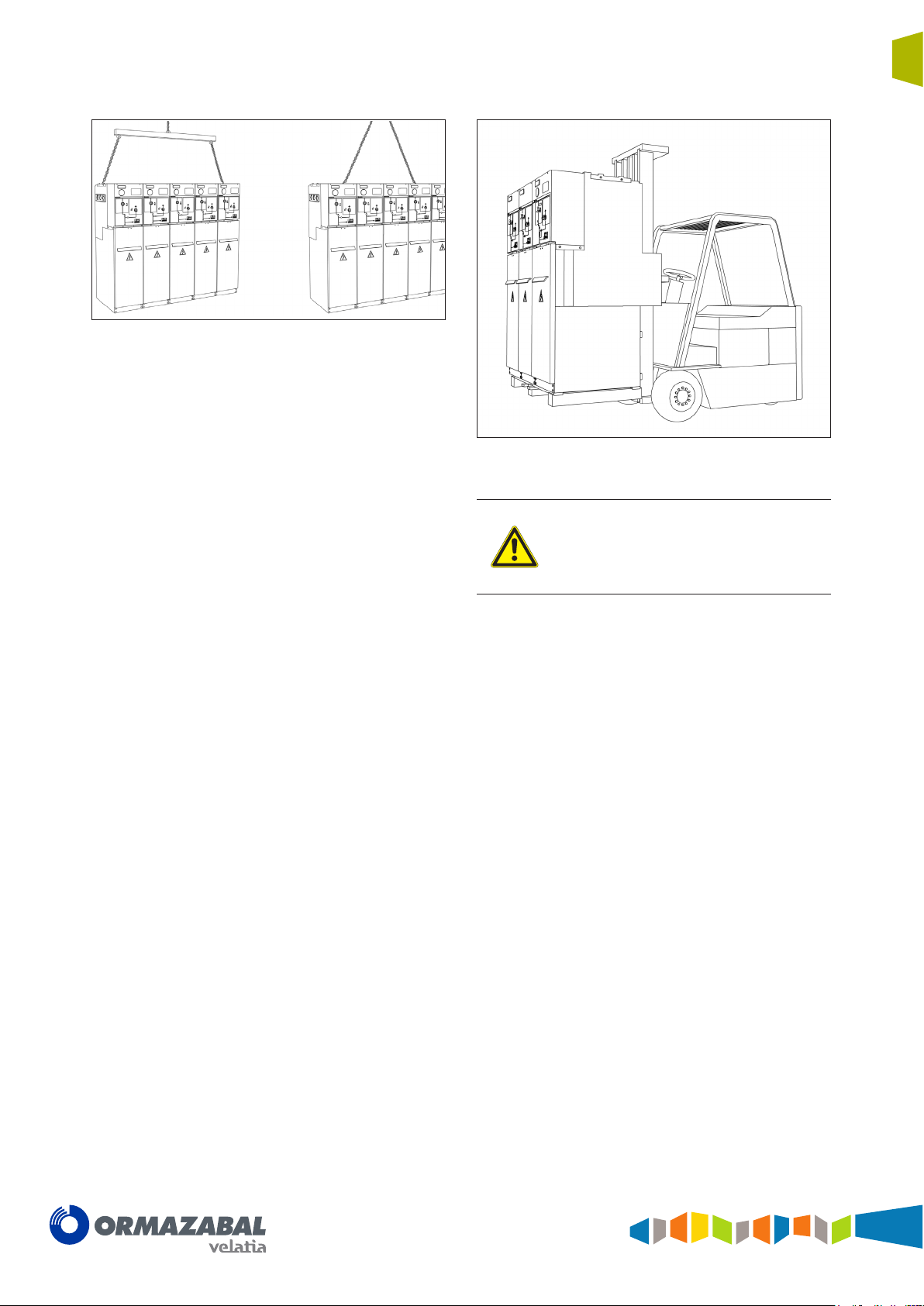
4. To handle sets of 5 functional cgm.3 units (consisting
of either coupled modules or compact assemblies
associated with modules), use lifting systems (slings,
lifting beam, etc.) with a pull angle greater than
65º and less than 115º in order to prevent possible
damage to the cubicles during hoisting.
2. Lifting using slings or chains fixed to the lifting
supports on the sides of the top of the cubicle. The
angle of pull should be as vertical as possible (with an
angle greater than 60º from the horizontal).
[5]
Position the rear of the cubicle facing the driver, to avoid damaging the front.
IG-136-EN version 10; 23/06/2016
General instructions
Handling and transport
cgm.3 system
Fully SF6 gas insulated medium voltage switchgear up to 40.5 kV in accordance with IEC Standards
Figure 2.3 Lifting a cgm.3 assembly with 5 functional units.
Figure 2.4 Lifting a cgm.3 assembly with a forklift truck.
15
The use of lifting beams is required for cubicle
assemblies with control boxes. As the sole
exception, slings may be used if the cubicles
of the assembly have identical height control
boxes installed.
IG-136-EN version 10; 23/06/2016
16
Storage
3 Storage
General instructions
cgm.3 system
Fully SF6 gas insulated medium voltage switchgear up to 40.5 kV in accordance with IEC Standards
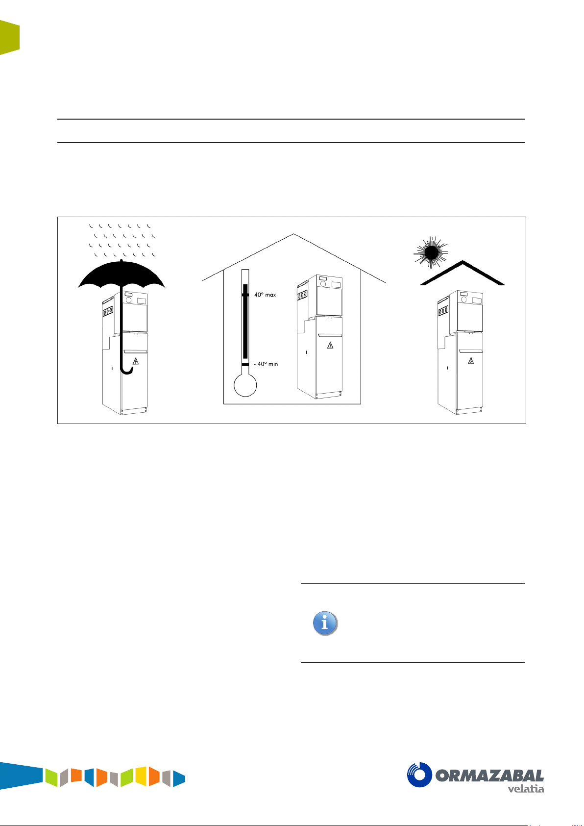
If it needs to be stored, the equipment must be placed on
dry ground or on top of damp-proof insulating material, still
in its original packaging.
Storage must always be INDOORS, with the following
conditions recommended:
1. Ambient air temperature should not exceed 40 ºC and
its mean value, measured in a period of 24 hours,
should not exceed 35 ºC.
2. The ambient air temperature should not drop below
- 5 ºC. There are also cubicles with storage
temperature up to - 40 ºC.
3. The switchgear must be protected from direct solar
radiation.
4. Altitude, both in transport and in storage, must not
exceed 2000 m.
5. The environmental air must not have any significant
contamination from dust, smoke, corrosive and/or
inflammable gases, vapours or salt.
After prolonged storage, clean all the insulating parts
carefully before commissioning the equipment. The
enclosure should be cleaned with a clean, dry lint-free
cloth.
a) the mean relative humidity value, measured over
a period of 24 hours, must not exceed 95%.
b) the mean water steam pressure value, measured
in a period of 24 hours, must not exceed 2.2 kPa.
c) the mean relative humidity value, measured over
a period of one month, must not exceed 90%.
d) the mean water steam pressure value, measured
in a period of one month, must not exceed
1.8 kPa.
7. During transport, vibrations caused by external
factors or seismic movements must be insignificant.
Any other conditions must be made known
beforehand, since the equipment
must be factory-set at atmospheric pressure in
the nal destination.
Otherwise the gauge may show an erroneous
reading, even though
the unit's interior pressure value is correct.
6. The switchgear must be protected from the rain, and
the humidity conditions should be as follows:
IG-136-EN version 10; 23/06/2016
General instructions
cgm.3 system
Fully SF6 gas insulated medium voltage switchgear up to 40.5 kV in accordance with IEC Standards
4 Installation
4.1 Unpacking the equipment
Installation
17
The switchgear of the cgm.3 system is supplied protected
in plastic as standard.
On receiving the equipment, check that the goods supplied
correspond to the order and associated documentation. If
this is not the case, contact Ormazabal immediately.
The disassembly process for the equipment is as follows:
1. Using a blade, cutter or similar tool, cut the cellophane
the cubicle is wrapped in
2. Completely remove the cellophane.
3. Detach the white polystyrene corner pieces.
4. Unscrew the fixings between the base and the pallet.
5. Remove the pallet, handling the cubicle as indicated
in section 2.1.
[6]
.
6. Unpack the accessory box located at the rear or on
7. Remove the self-adhesive protective plastic from the
8. Dispose of any waste in an environmentally-friendly
It is advisable to make a visual inspection of the equipment
to check whether it has suffered any damage in transit. If
damaged, contact Ormazabal immediately.
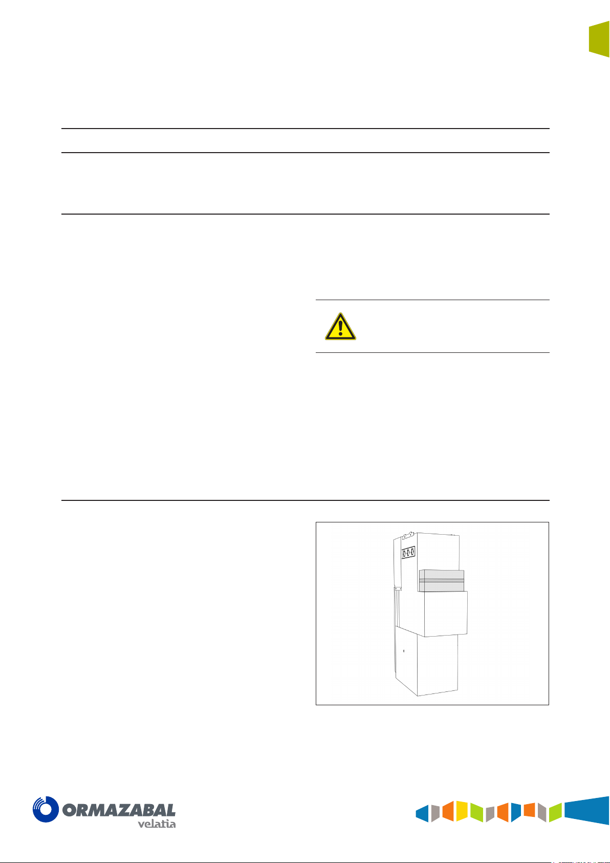
4.2 Location of accessories during transport
A number of accessories are supplied with the cubicles,
located as indicated in the figures below:
top of the cubicle.
cable compartment cover.
The self-adhesive plastic must be removed
from the cable compartment cover so that the
equipment enclosure's earth connection may
have the proper electrical continuity.
manner.
Figure 4.1 Location of accessories in cgm.3-p cubicles
[6]
It is advisable to cut the cellophane at the rear of the cubicle or at the corner to avoid scratching the surface.
IG-136-EN version 10; 23/06/2016
18
Installation
Fully SF6 gas insulated medium voltage switchgear up to 40.5 kV in accordance with IEC Standards
Figure 4.2 Location of accessories in cgm.3-l and cgm.3-v
cubicles
General instructions
cgm.3 system
Depending on the cubicle model, the accessory box
contains some of the following items:
• General Instructions Document IG-136 by
Ormazabal.
• Driving lever
• Spring charge lever
• Cubicle connecting kit:
- ormalink
- Springs
- Syntheso grease
- Earthing bar
• End plug kit:
- Cubicle end assembly
- Nylon thread
- Plastic plugs
- Side cover
• Floor fastening assembly
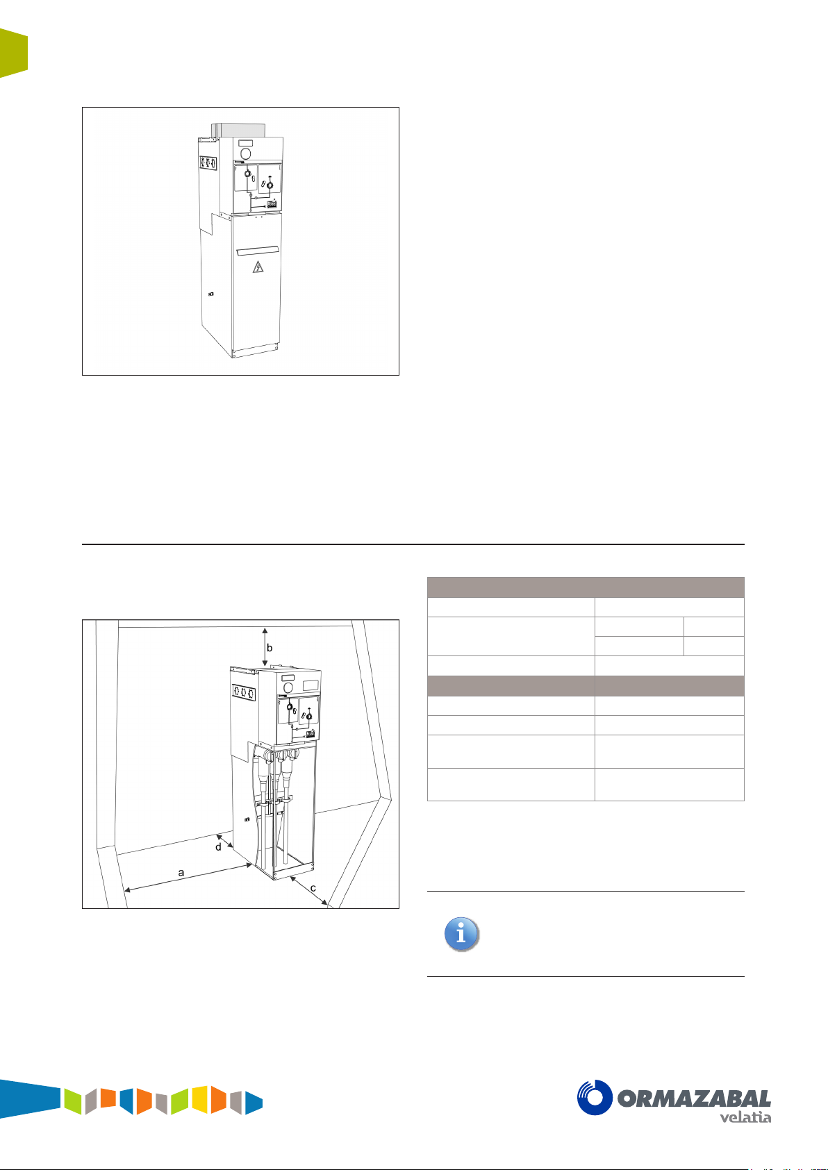
4.3 Minimum installation distances
The minimum distances to the walls and ceiling which
must be maintained in the installation are as follows:
Figure 4.3 Minimum installation distances
Minimum distances [mm]
Side wall (a) 100
Roof (b)
Front clearance (c) 500 (*)
Height 1400 mm 600
Height 1745 mm 550
Function Rear wall (d)
cgm.3-l / -s / -v / -2lv / -rb / -rc
cgm.3-p / -2lp
cgm.3-m without IAC
classification
cgm.3-m with IAC
classification
(*) An operating clearance of at least 1000 mm is recommended.
(**) Cubicles with classification IAC AFLR: d = 800 mm.
(***) Diagrams combined with p and 2lp cubicles.
(****) For classification IAC 21 kA – 1 s.
The measurements indicated in the table
have been obtained in accordance with the
dimensions of the test room for the gas insulated
modules, in accordance with Annex AA of
Standard IEC 62271-200.
100 / 160(***)
0
0
100 / 150(****)
[7]
For any doubts, please ask Ormazabal.
The space required to extend the assembly with an
additional cubicle is 250 mm plus the width of the new
cubicle
[7]
.
IG-136-EN version 10; 23/06/2016
General instructions
cgm.3 system
Fully SF6 gas insulated medium voltage switchgear up to 40.5 kV in accordance with IEC Standards
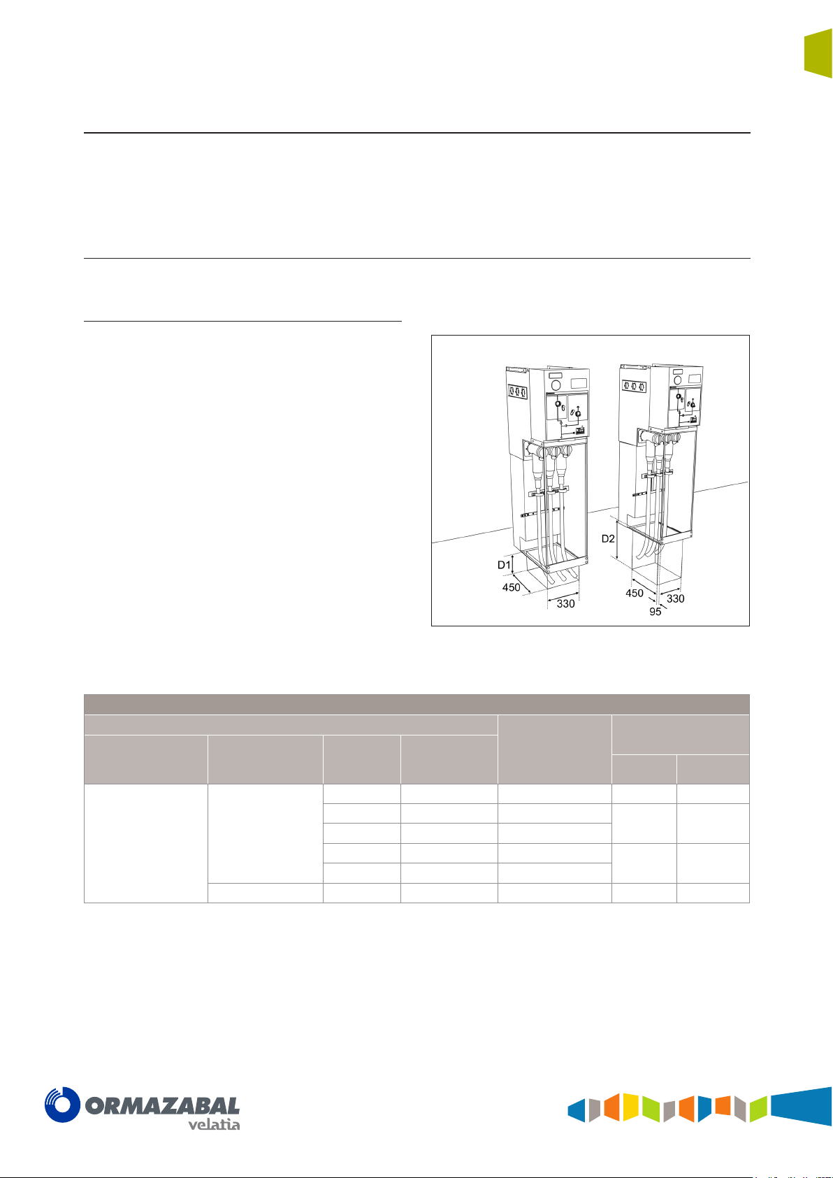
4.4 Recommended cable connection trench
Installation
19
Minimum recommended dimensions based on the trench
dimensions used in the tests in accordance with Standard
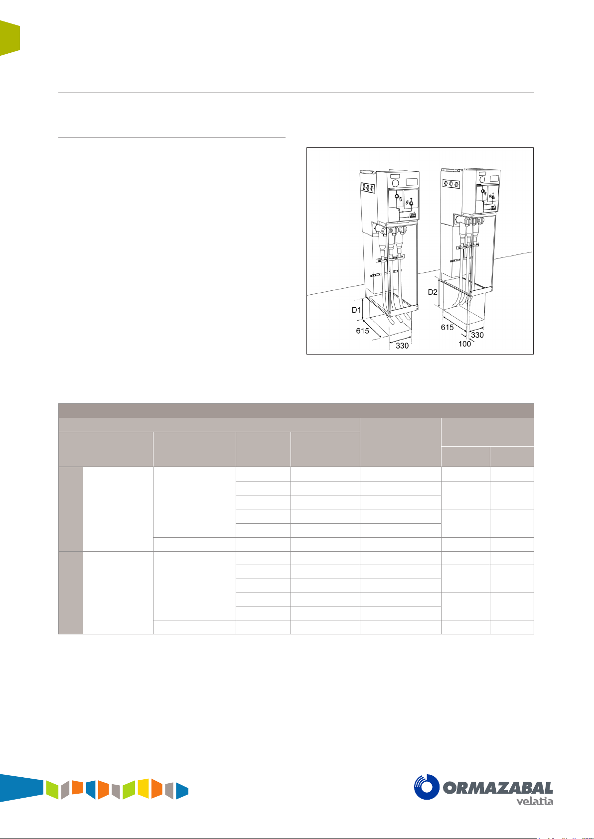
4.4.1 Cubicles with internal arc in gas tank
[8]
up to 20 kA
Feeder function, busbar rise and cable rise
The dimensions of the trench depend on the minimum
radius of curvature of the cables used.
Front and rear
cable input or output
Side cable input or
(D1)
output (D2)
IEC 62271-200. In accordance with the radius of curvature
of the cables used, these dimensions may vary
[9]
- 0.5 s
[10]
.
Figure 4.4 Dimensions [mm] of the cable trench for cgm.3-l,
Trench necessary for the feeder, busbar rise and cable rise function
Cable data
Cable insulation Cable type
Dry insulation
Check against the data of the manufacturer of the cable used.
(*)
[9]
Tests conducted with a current of 21 kA.
[10]
In each case, bear in mind which cable is to be used in that particular installation.
Single-core 18/30 kV
3-core 18/30 kV < 150 92.7 805 650 650
Cable section
[mm
< 150 41 555 200 500
185 43 590
240 45.2 640
300 47.5 685
400 48 745
2
]
Cable diameter
[mm]
cgm.3-rb and cgm.3-rc
Approximate radius
of curvature*
[mm]
Minimum depth
D1 [mm] D2 [mm]
200 550
300 660
IG-136-EN version 10; 23/06/2016
20
Installation
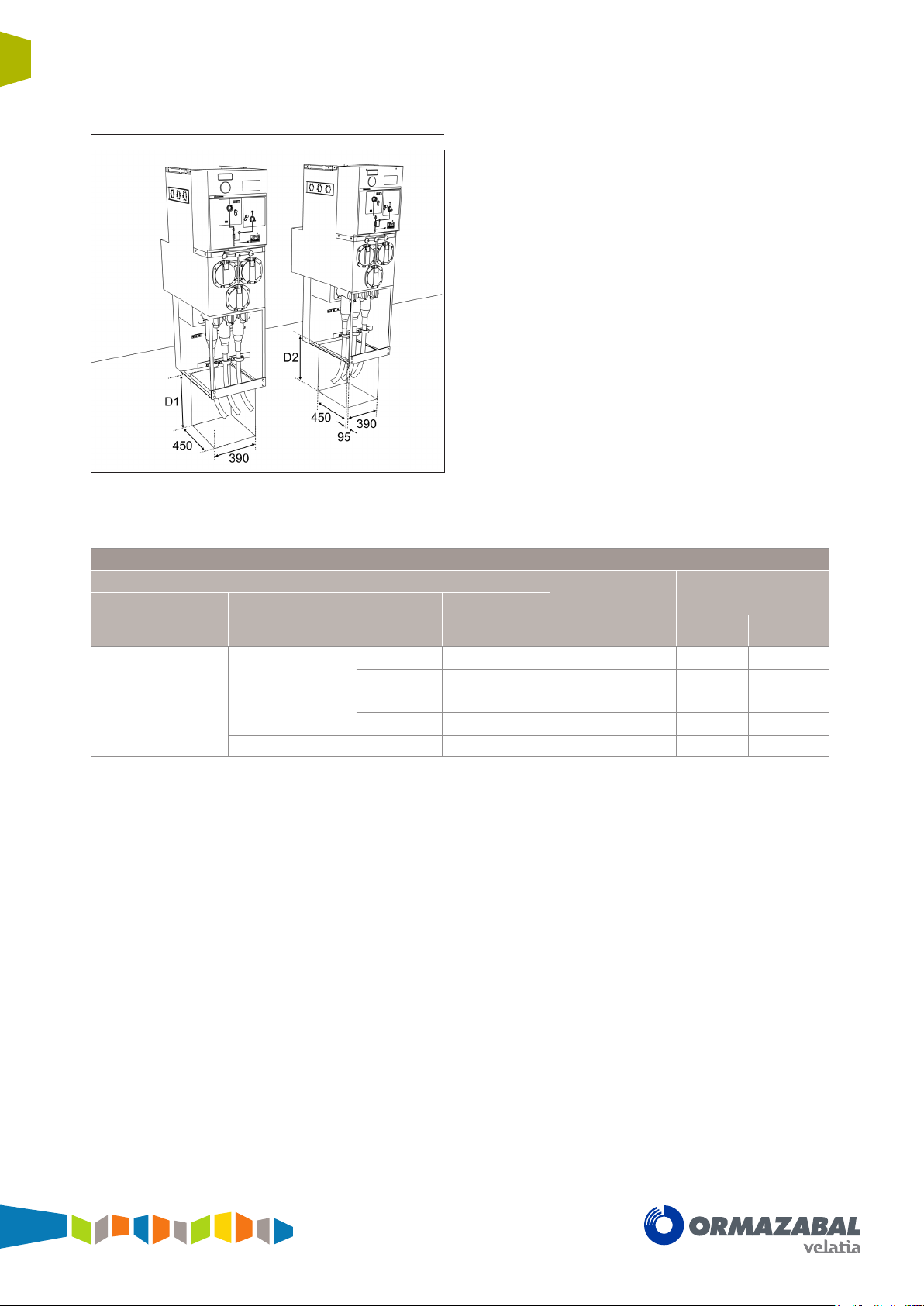
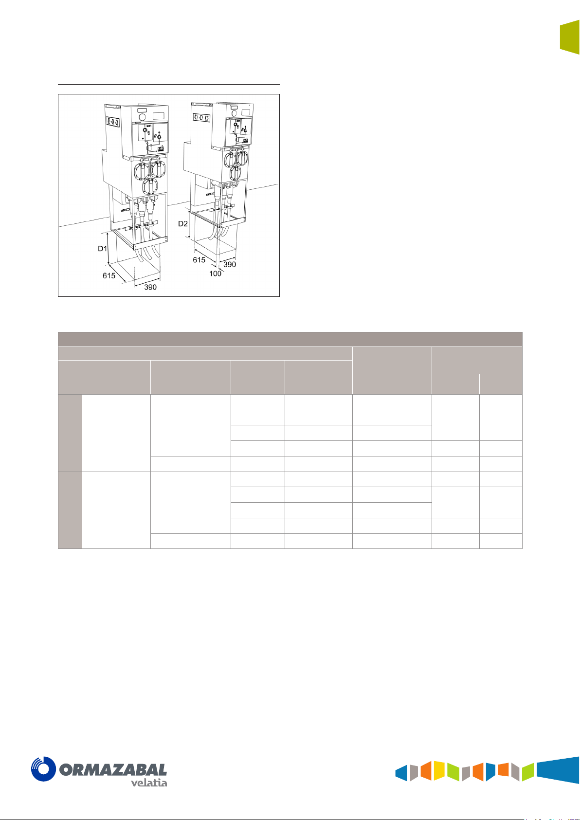
Fuse protection function
General instructions
cgm.3 system
Fully SF6 gas insulated medium voltage switchgear up to 40.5 kV in accordance with IEC Standards
Front and rear cable input
or output (D1)
Side cable input or
output (D2)
Figure 4.5 Dimensions [mm] of the cable trench for cgm.3-p
Trench necessary for the fuse protection function
Cable data
Cable insulation Cable type
Dry insulation
(*) Check against the data of the manufacturer of the cable used.
Single-core 18/30 kV
3-core 18/30 kV < 95 86 735 1050 1050
Cable section
2
]
[mm
< 50 35 430 500 500
70 36.5 460
95 38 500
150 41 555 600 600
Cable diameter
[mm]
Approximate radius
of curvature*
[mm]
Minimum depth
D1 [mm] D2 [mm]
550 550
IG-136-EN version 10; 23/06/2016
General instructions
cgm.3 system
Fully SF6 gas insulated medium voltage switchgear up to 40.5 kV in accordance with IEC Standards
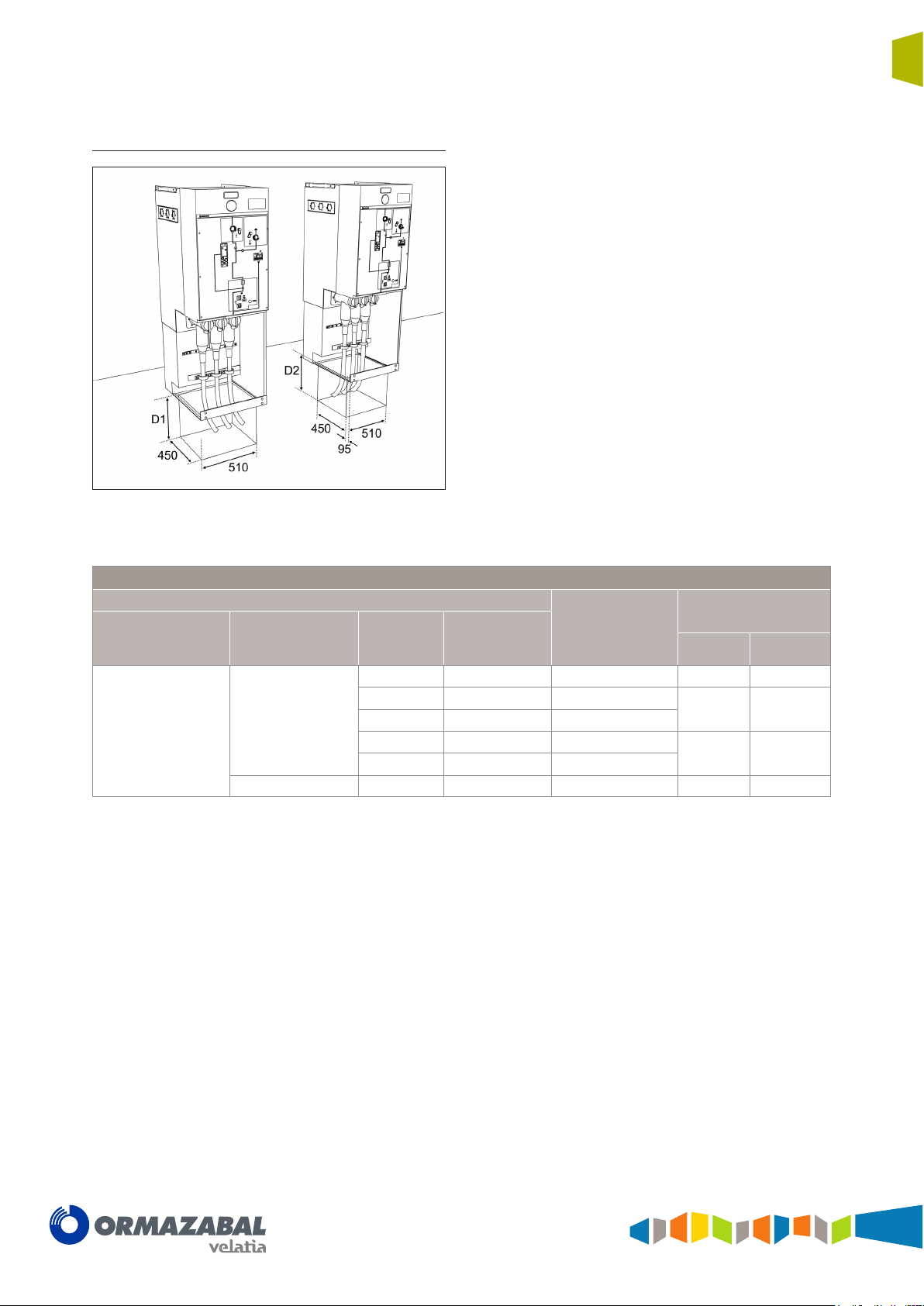
Circuit-breaker function with AV / RAV
driving mechanism
Front and rear cable input
or output (D1)
Side cable input or
output (D2)
Installation
21
Figure 4.6 Dimensions [mm] of the cable trench for cgm.3-v
with AV / RAV driving mechanism.
Trench necessary for the circuit-breaker function with AV / RAV driving mechanism
Cable data
Cable insulation Cable type
Dry insulation
(*) Check against the data of the manufacturer of the cable used.
(**) 150 mm2 cable only valid up to 21 kA.
Single-core 18/30 kV
3-core 18/30 kV < 150 92.7 805 850 850
Cable section
2
]
[mm
<150 (**) 41 555 400 400
185 43 590
240 45.2 640
300 47.5 685
400 48 745
Cable diameter
[mm]
Approximate radius
of curvature*
[mm]
Minimum depth
D1 [mm] D2 [mm]
400 500
500 600
IG-136-EN version 10; 23/06/2016
22
Installation
Fully SF6 gas insulated medium voltage switchgear up to 40.5 kV in accordance with IEC Standards
4.4.2 Cubicles with classification of internal arc IAC up to 25 kA - 1 s
Feeder function, busbar rise and cable rise
Front and rear
cable input or output
(D1)
Side cable input or
output (D2)
General instructions
cgm.3 system
Trench necessary for the feeder, busbar rise and cable rise function
Cable data
Cable insulation Cable type
Dry insulation
Height 1400 mm(***)
Dry insulation
Height 1745 mm
(*) Check against the data of the manufacturer of the cable used.
(**) 150 mm2 cable only valid up to 21 kA.
(***) Exclusively for cgm.3-l and cgm.3-2lp cubicles.
Single-core 18/30 kV
3-core 18/30 kV < 150 92.7 805 950 950
Single-core 18/30 kV
3-core 18/30 kV < 150 92.7 805 650 650
Cable section
2
]
[mm
< 150 (**) 41 555 500 800
185 43 590
240 45.2 640
300 47.5 685
400 48 745
< 150 (**) 41 555 370 500
185 43 590
240 45.2 640
300 47.5 685
400 48 745
Figure 4.7 Dimensions [mm] of the cable trench for cgm.3-l,
Cable diameter
[mm]
cgm.3-rb and cgm.3-rc
Approximate radius
of curvature*
[mm]
Minimum depth
D1 [mm] D2 [mm]
550 900
650 1000
370 550
370 660
[11] In each case, bear in mind which cable is to be used in that installation.
IG-136-EN version 10; 23/06/2016
General instructions
cgm.3 system
Fully SF6 gas insulated medium voltage switchgear up to 40.5 kV in accordance with IEC Standards
Fuse protection function
Front and rear cable input
or output (D1)
Side cable input or
output (D2)
Installation
23
Figure 4.8 Dimensions [mm] of the cable trench for cgm.3-p.
Trench necessary for the fuse protection function
Cable data
Cable insulation Cable type
Dry insulation
Height 1400 mm
Dry insulation
Height 1745 mm
(*) Check against the data of the manufacturer of the cable used.
Single-core 18/30 kV
3-core 18/30 kV < 95 86 735 1400 1400
Single-core 18/30 kV
3-core 18/30 kV < 95 86 735 1050 1050
Cable section
2
]
[mm
< 50 35 430 800 800
70 36.5 460
95 38 500
150 41 555 950 950
< 50 35 430 500 500
70 36.5 460
95 38 500
150 41 555 600 600
Cable diameter
[mm]
Approximate radius
of curvature*
[mm]
Minimum depth
D1 [mm] D2 [mm]
900 900
550 550
IG-136-EN version 10; 23/06/2016
 Loading...