

Page 1
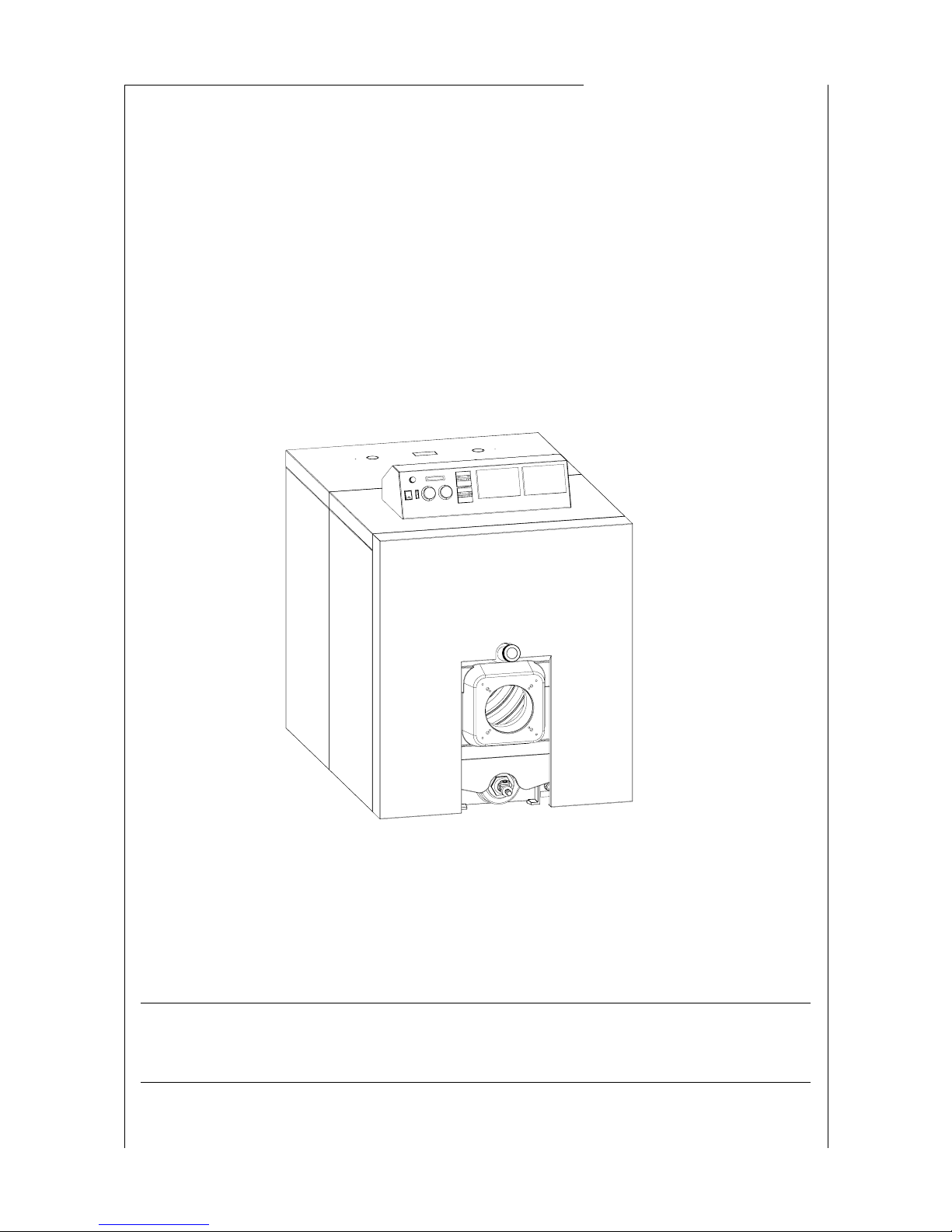
INSTALLATION COMMISSIONING AND OPERATING MANUAL
CAST IRON OIL-FIRED BOILER
Commodore Plus (uk) - 1007-01
Commodore Plus
Hartley and Sugden
Page 2

1. Technical data ............................................................................................4
2. Layout of the heating installation of the boiler ...........................................5
3. Assembly of the boiler ...............................................................................7
4. Hydraulic installation ofthe boiler ...........................................................23
5. Protection of chimneys against internal condensations ...........................26
6. Electrical connections ..............................................................................27
7. Spare parts list ......................................................................................... 31
8. Maintenance ............................................................................................. 36
9. Guarantee conditions on the products .....................................................36
-Theboiler mustbe installed and commissioned by a registered installer in accordance withinstructions herewith.
- It is important for the safe operation of boilers that there is sufficient fresh air inlet and ventilation provided.
- Maintenance of the boiler should be done once or twice a year, depending on the conditions of use.
- It is inadvisable to regula rly drain down the boiler as frequent additions of fresh water may bring about the
premature deterioration of the boiler fabric through the d eposit of mineral substances present in the water.
- Precautions must be taken to avoid any damage that might be caused by frost .
User's advices
CONTENTS
Page
Hartley and Sugden
Page 3

Page 3 / 36
Hartley and Sugden
General rules
The flues of the products of combustion must be
calculated and carried out according to the standards
in force, the local obligations and the regulations of the
manufacturer.
The hydraulic installations, fuel or gases will be
established according to standards of installation and
safety in force in the country of use.
Page 4
Page 4 / 36
Hartley and Sugden
111
719
63
399
321
321
830
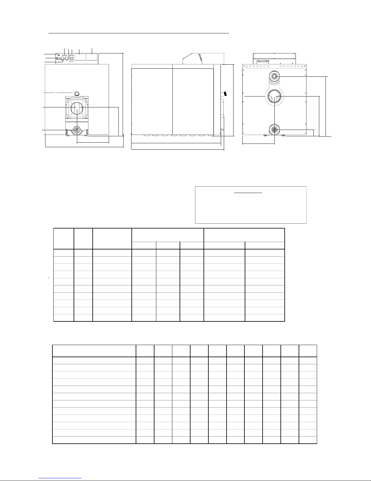
1. Technical data
Maximum wat er t emper atu re: 90 °C; maximum inst allat ion pre ssur e: 4 b ar
REMARK:
The temperature adjusted on the second step
thermostat H/L (switch nr. 8) should be lower
than the one on the first step thermostat
(switchnr. 7).
1. Main switch with on/off light
2. Boiler thermometer
3. Safety limit with manual reset (110°C )
4. Burner opening: diam. 170 mm standard.
5. Opening drain cock: 3/4"
6. Eyepiece to view flame
7. First step thermostat (e.g. of adjustment : 80°C)
8. Second step thermostat
9. Place foreseen for the control system
10. Plac e foreseen for hour meters
Height Wi dth De pth Ø Depth
122 5 200,0 1165 900 1300 400 790
132 6 237,5 1165 900 1300 400 920
241 7 275,0 1165 900 1560 400 1050
242 8 312,5 1165 900 1560 400 1180
234 9 350,0 1165 900 1820 400 1310
244 10 387,5 1165 900 1820 400 1440
335 11 425,0 1165 900 2080 400 1570
345 12 462,5 1165 900 2080 400 1700
355 13 500,0 1165 900 2340 400 1830
455 14 537,5 1165 900 2340 400 1960
Type
ABC
Total
numb.
section
Boiler dimension (mm) Dim. chambre de combustion
Net he at
output (k W)
A = number of front inter sections
B = number of middle inter sections
C = number of rear inter sections
Comm odore Plus N° 122 132 241 242 234 244 335 345 355 455
Max. heat input (kW) 178 225 246 278 312 340 375 407 430 474
Net heat output (kW) 162 204 224 253 283 310 339 371 394 432
Net heat output (kW) t o 1*CE 92/42 (*) 200 237,5 275 312,5 350 387,5 425 462,5 500 537,5
Number of sections 7 8 9 10 11 12 13 14 15 16
Furnace pressure (mbar) 2,9 3,50 2 ,2 0 2,60 3,70 3 ,5 0 3,60 4,40 4,6 0 4,60
ǻ T° flue - T ° ambiance 156 160 156 161 160 152 162 153 141 150
Load losses water side ( mbar) ǻT 15°C 4,5 7,1 8,5 14 1 6,7 19,5 22,6 26,7 29,6 35
Exit flue gas mass flow (g/s) 75 97 103 116 132 147 163 176 185 205
Combust ion circuit (dm³) 195 226 258 290 322 354 386 418 450 482
Relative standby loss (%) 0,6 0,51 0,48 0,44 0,4 0,38 0,35 0,32 0,3 0,29
Water capacity of the boiler (l) 115 130 145 160 175 190 205 220 235 250
Heat ing body weight (kg) 705 800 895 980 1060 1150 1240 1330 1420 1510
Outlet (3")
3
Flue
Inlet (3")
9
7
4
812
6
5
* : n° 7-8 inter (+260 mm)
: n° 9-10 inter (+520 mm)
: n° 11-12 inter (+780 mm)
: n° 13-14 inter (+1040 mm)
910
900
388
1253*
1295
838
450
1165
155
1007
450
558
88
Ø 180
Maximum wat er t emper atu re: 90 °C; maximum inst allat ion pre ssur e: 4 bar
(*):forindication
Page 5

Page 5 / 36
Hartley and Sugden
2. Layout of the heating installation of the boiler
The boiler must be installed and commissionedby a registered installer.
The installer must make the necessary arrangements on site to ensure that the positioning and the fitting of the boiler, the
supply of combustion air, ventilation of the boiler house, connection of the gas supply and the removal of the combustion
gases via the flue systemare all in conformity with theprevailing regulationsand standards. Inthe followingparagraphs, Saint
We remind you of some rules concerning the above asp ects. If the conditions summarised above are not strictly adhered to
and resulting damage occurs then our guarantee would be invalidated.
2.1. Positioning
The boiler must notbe installed in areas where there is a significant riskof frostdamage or where there is a risk ofthe combustion
air being contaminated with halogenated substances (e.g. chlorine, detergents, aerosols, etc.), printing establishments, dry
cleaning establishments, laboratories, etc..., unless sufficient measures have been taken to ensure the supply of unpolluted
combustion air.
2.2. Aeration and ventilation of the boiler room
It is important for the safe operatio n that there are sufficient areas of fresh air inlet and ventilation provided to the room in
which the boiler is installed.
2.3. Installation of the boiler
The boiler must be positioned in accordance withprevailing standards, as far as possible from any wall surface that may be
damaged by heat (wood, etc...); if necessary cover the wall with an insulated panel.
The boiler must be placed in such a way that it can easily be maintained and r egularly checked.
2.4. Warning of the extractors and burners
When using combustion gas extractors, it is necessary to control to the extractors the functioning of the burners, so that those
ones cannot start if the extractors have not been brought into service beforehand and that they stop immediately in the event
of stop of the extractors.
2.5 . Non-specific burners compatibility
When using a non-specified burner - i.e. a burner whichhas not been supplied with the boiler, the installer must satisfy himself
that he has chosen technical compatible equipment and verify the operation of the equipment after start up.
2.6. Thermal shocks and corrosion on combustion produce side
For burners it is necessary to limit the fuel flow rate, taking the efficiency into account so that the instantaneous output of
the burner cannot exceed the normal or maximum boiler output or peak boiler output as determined by the manufacturer.
Page 6
Page 6 / 36
Hartley and Sugden
2.7. Discharge of combustion products
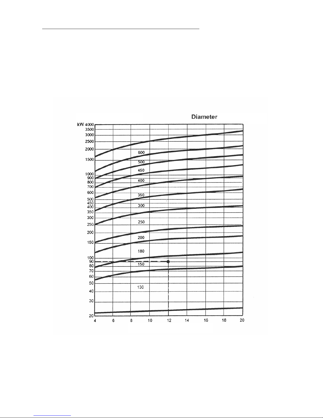
The chimney will be det ermined (height and section) in function of the boiler used, it will be capable of discharging the
combustion gases, maintaining a vacuum in the furnace (see "draught losses" in the table page 3).
If it is impossible to provide sufficient vacuum, it is possible to use a flue gas extract or, the characteristics of this one will
be given in function of the boiler to connect.
TEMPERATURE OF SMOKE : 160° C
OUTPUT
(mm)
HEIGHT (m)
Page 7
Page 7 / 36
Hartley and Sugden
- A base must be built according to good engineering practice, considering the dimensions and the weight of the
heating boiler
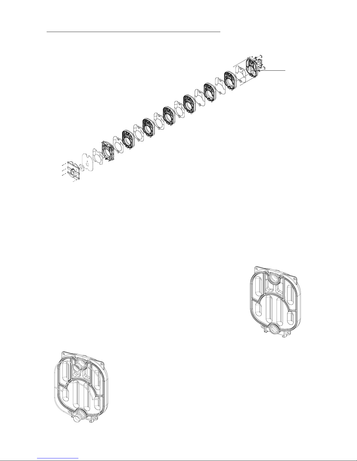
- Start the installation with the rear boiler section ( A1)
3. Assembly of the boiler
3.1. Cast iron body installation
A
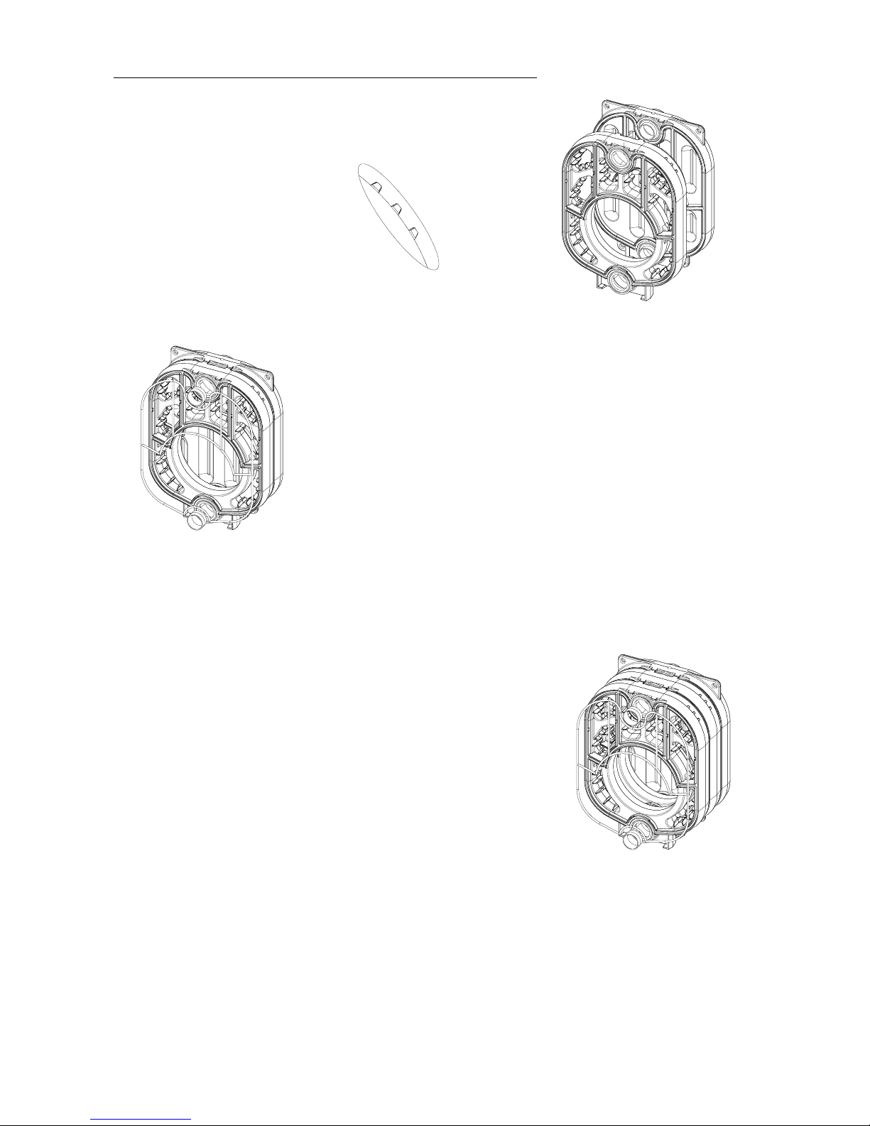
1. Position the rear boiler section verticallyat thechosen place, also determined
by the overall dimensions of the boiler (jacket included).
2. Coat the section ribs with adhesive (supplied with the installation accessories)
and attach the lengths of sealing cord ( code n° 1-30-240-60410 / Ø 10mm ) in the
section ribs. Carefully degrease the double-taper nipples and bores. Coat t he
nipples with compound ( supplied with the i nstallation accessories ). Drive the
double-taper nipples into the bores using a mallet or a ha mmer. It is extremely
important that the nipples should be driven in smoothly and exactly in t he centre
line of the bore.
Page 8
Page 8 / 36
Hartley and Sugden
3. Insert the rear intermediate section ( attention with the visual code on the
section ).
4. Coat the section ribs with adhesive (supplied with the installation accessories)
and attach the lengths of sealing cord ( code n° 1-30-240-60410 / Ø 10mm ) in the
section ribs. Carefully degrease the double-taper nipples and bores. Coat t he
nipples with compound ( supplied with the i nstallation accessories ). Drive the
double-taper nipples into the bores using a mallet or a ha mmer. It is extremely
important that the nipples should be driven in smoothly and exactly in t he centre
line of the bore.
5. Repeat the operation according to the number of rear inter, see table
page 3 in our exampleof illustration : 2 x.
Page 9
Page 9 / 36
Hartley and Sugden
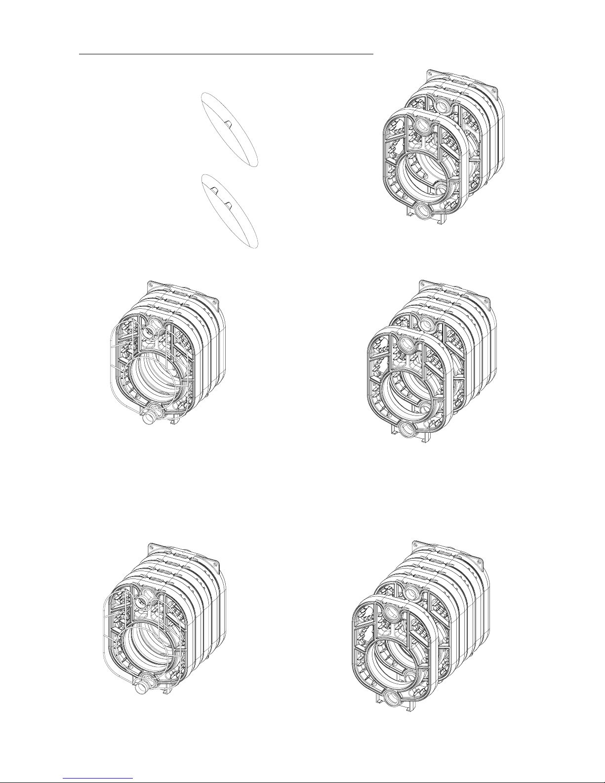
6. Follow the same procedure as for the points 3 to 5 for the inter middle sectio ns
and front inter by taking care to check well the visual code on the cast-iron section:
- front inter section
-middleintersection
7.
8.
9.
10.
Page 10
Page 10 / 36
Hartley and Sugden
11.
12.
13.
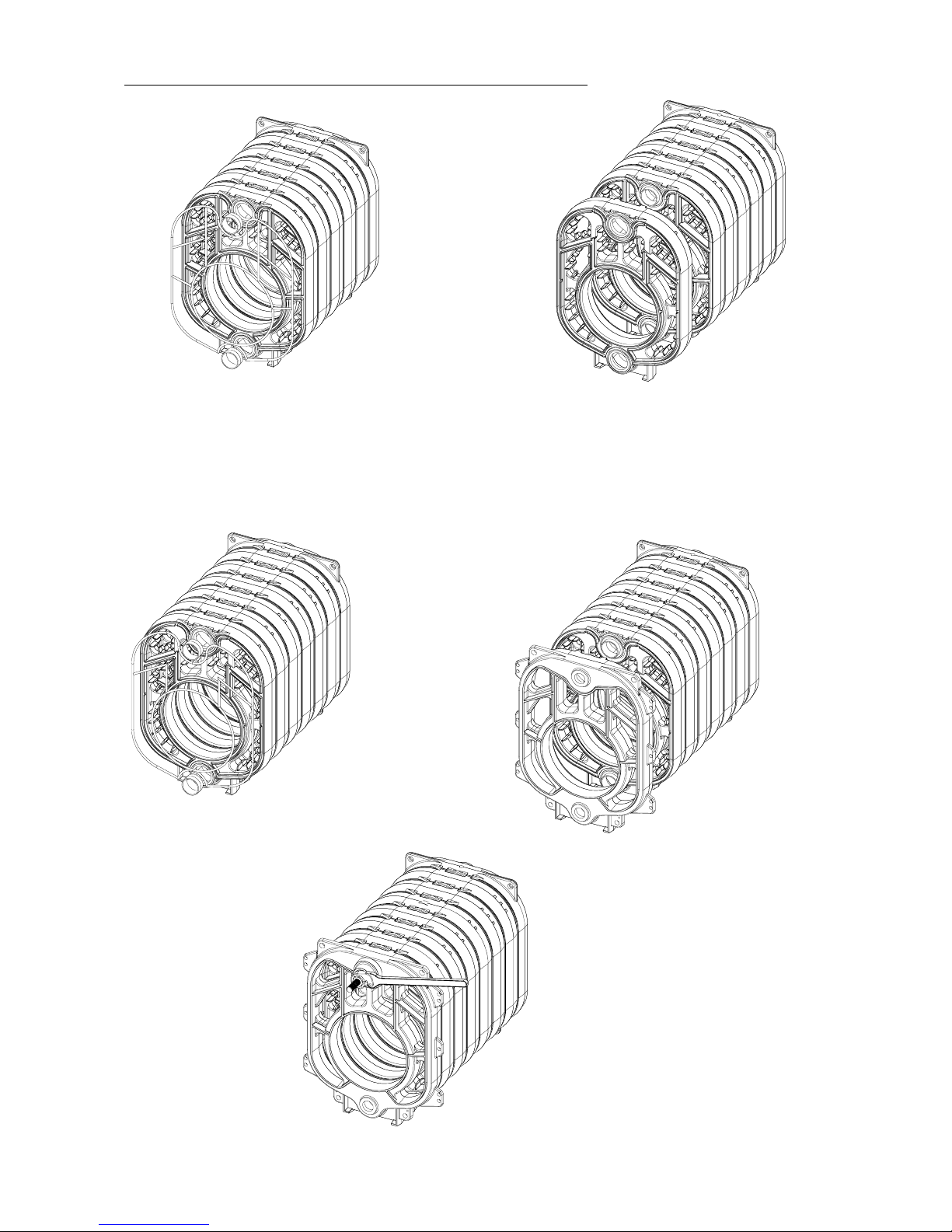
14. Insert the front section. Install theassembly equipment according
to the drawing hereafter and tighten the nuts of both mounting
bars at the same time.
Page 11
Page 11 / 36
Hartley and Sugden
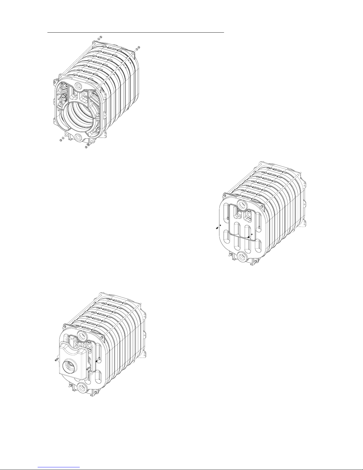
15. Installation of the tie rods for assembly of the cast iron body. Insert the
4 tie rods in the lugs of the front and rear sections.
On the front face : 4 plain washers M16.
4 nuts DIN934 M16.
On the rear face : 4 plain washers M16.
4 nuts DIN934 M16.
Once the tie rods have been installed, unscrew the nut of the mounting
bar and remove the front plate. Remove the mounting bars.
16. Flue gas box installation.
Screwthe 2 studs DIN 939 12x90 ( code n° 1-80-300-12090 ) into the
tapped holes in the rear section, the end with the shortest thread
in the section.
17. Place thesiliconed rope Ø14mm (code 1-30-240-60114) inthe throat of
the flue gas box and fix this one with help of 2 washers M12 and 2 nuts
DIN934 M12.
Page 12
Page 12 / 36
Hartley and Sugden
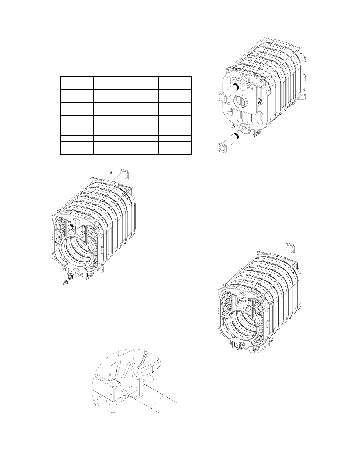
18. Place the tube of 3s with its flange on the boiler outlet. According
to the configurations, there might be an inlet water injecto r, this
one is always placed on the boiler inlet. If no inlet water injector
in the configuration, place the second t ube of 3s with its flange on
the boiler inlet.
19. Place the plunger in the foreseen opening on the rear section, place a
plug with hexagon head of 2s on the front sect ion in upper part and a
fittingreduction from 2s to 3/4s aswellas a draincock 3/4s in lower part.
20. Screw the 2 hinges into the tapped holes in the front section ( left
or right side according to the direction opening selected). Respect
the distance of 60mm as showed on fig 21b. then place the washer
M16 and the nut M16 to block la r otation of the hinge.
20b.
60
Type
Pipe i n jectors
L= 70mm
Pipe injectors
L= 140 mm
Pipe i n jectors
L=190 mm
122
132
241
242 X
234 X
244 X
335 X
345 X
355 X
455 X
Page 13
Page 13 / 36
Hartley and Sugden
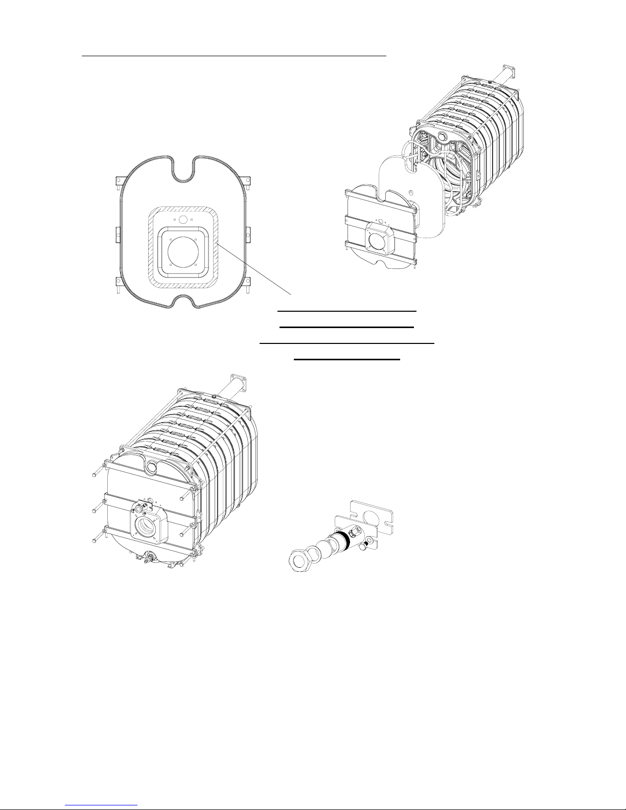
21. Place 2 i nsulations in the burner fixing flange then come to place
the door insulation by sticking it on the do or, see fig. 21A. Place
therope Ø 20mm(code 1-30-240-60120)in the grooveof thedoor
insulation. Position the door on the hinges.
22. Tighten the door against the front section with help of screws
M16x120 and washers M16. Then place the sightflame according
to fig. 22A.
3.2. Hydraulic test
- After having assembled the cast iron block, the boiler must be subjected to an hydraulic pressure test higher than 30%of
the maximuminstallation pressure i.e. 1,3 x 4 = 5,2 bar , this before assembly of the insulation and the mantle. During this
operation, no defect of leaks must appear.
ZONE TO AFFIX THE
GLUE IN ORDER TO
AVOID THE COMBUSTION
GAS LEAKAGES
21A.
22A.
Page 14
Page 14 / 36
Hartley and Sugden
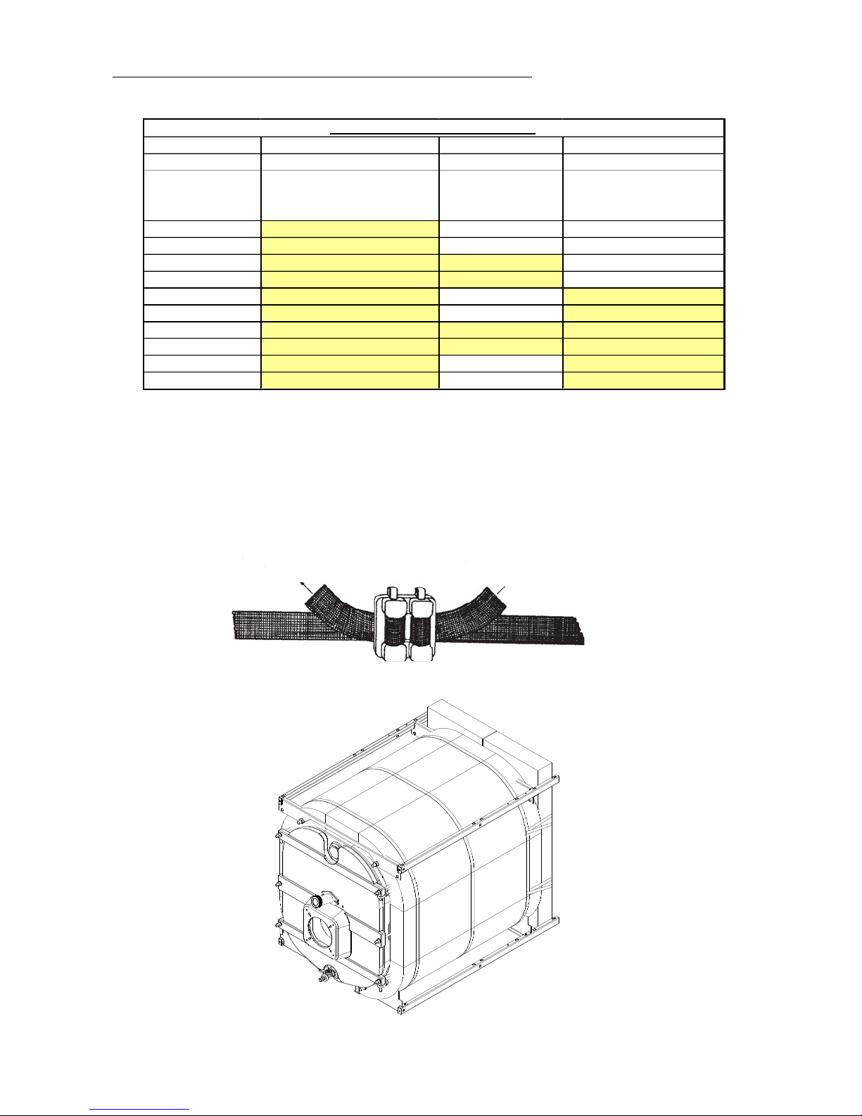
3.3. Jacket installation
DO NOT TIGHTEN TOO MUCH TO OBTAIN OPTIMAL INSULATION
3.3.1. Insulation installation (mantle)
1. Place the insulation around the heating body while taking care t o engage this o ne below the heating body.
2. Bind it with 3 (6) ta pes (see schema here under).
Caution the first(s) tape(s) A, must be at +/- 5 cm of the edge of the insulation.
3. Place the rear insulation on the rear section
4. Place the 2 rear tapes (see schema here under : example for a 132 (6) model).
Pull Pull
Assembly hoopingand buckles reinforced: tightening
Basic parcel = casing (122-132) Extens ion Lg: 260mm Extension Lg: 520mm
Commodore Plus 4-15-000-10006 4-15-000-10026 4-15-000-10052
Number of
intermed ia t e s ec t ion s
n° 5
(12 2) 1 - -
n° 6
(13 2) 1 - -
n° 7
(24 1) 1 1 -
n° 8
(24 2) 1 1 -
n° 9
(23 4) 1 - 1
n° 10
(244) 1 - 1
n° 11
(335) 1 1 1
n° 12
(345) 1 1 1
n° 13
(355) 1 - 2
n° 14
(455) 1 - 2
Casing composition Commodore Plus
Page 15
Page 15 / 36
Hartley and Sugden
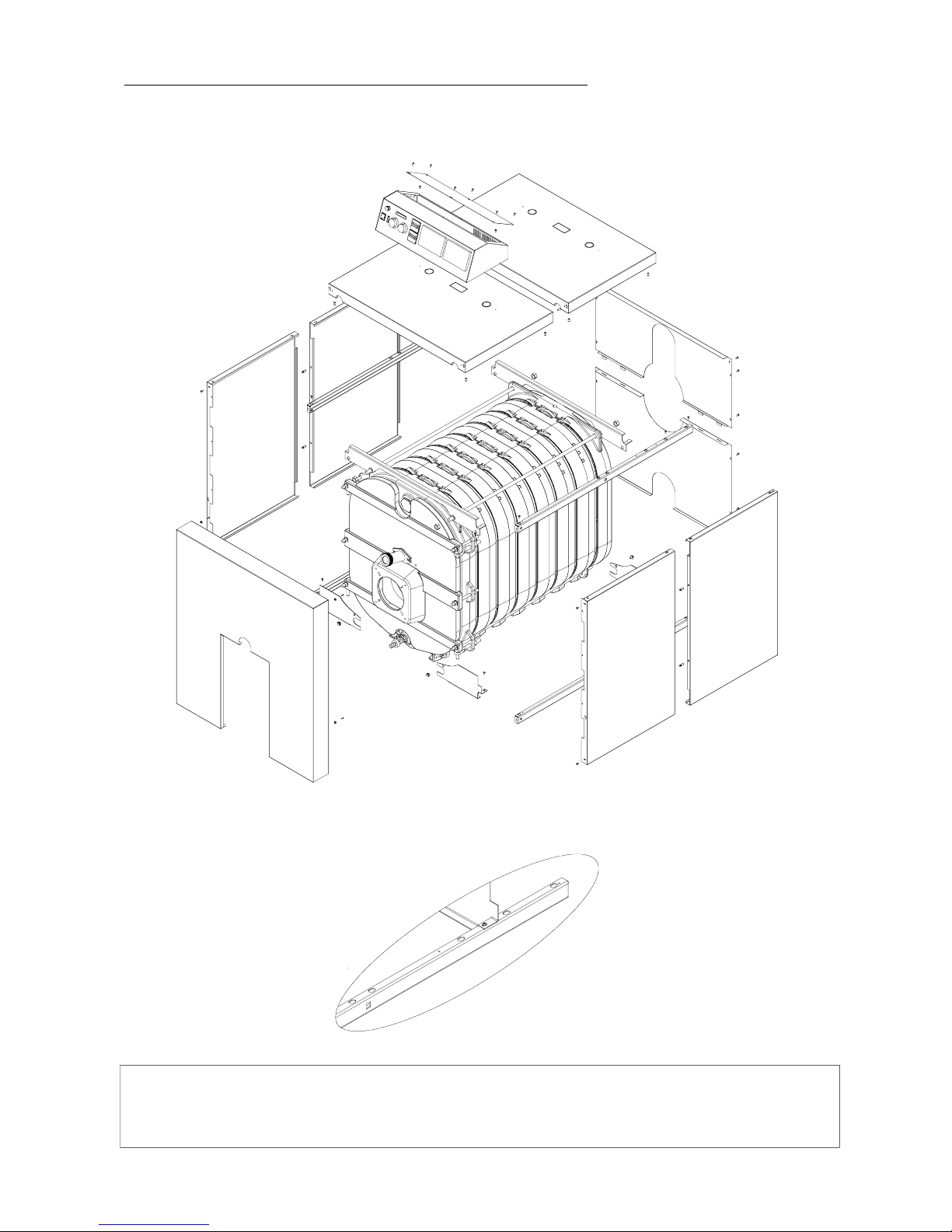
3.3.2. Sectional drawing for the Commodore Plus 5 & 6 (122 - 132)
Nb: The right and left lower and upper guides are locatable thanks to the square
cutting of 10 x 10 in the middle of the guide and on the upper edge of the panels.
A
DÉTAIL F
ECHELLE 1 : 4
Page 16
Page 16 / 36
Hartley and Sugden
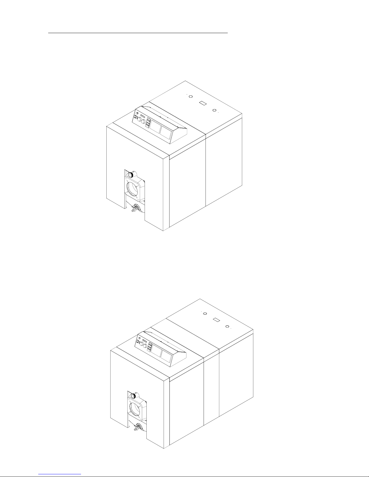
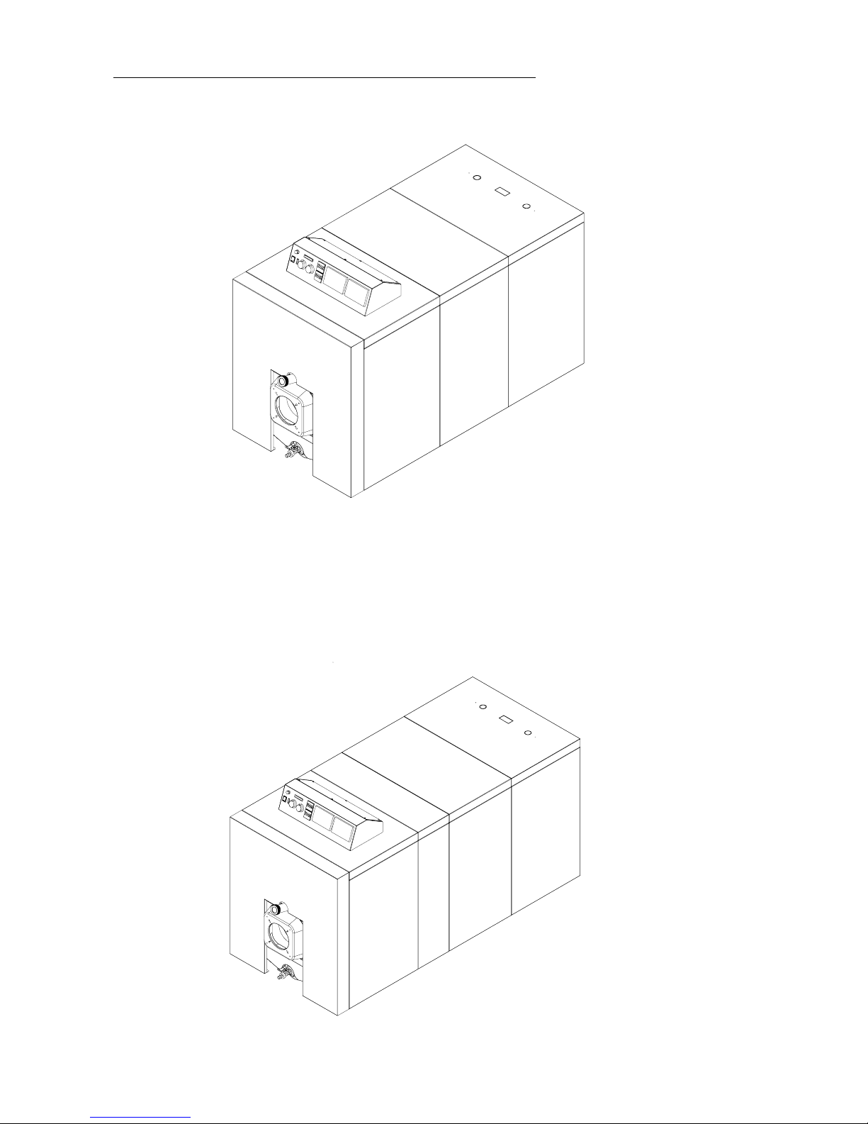
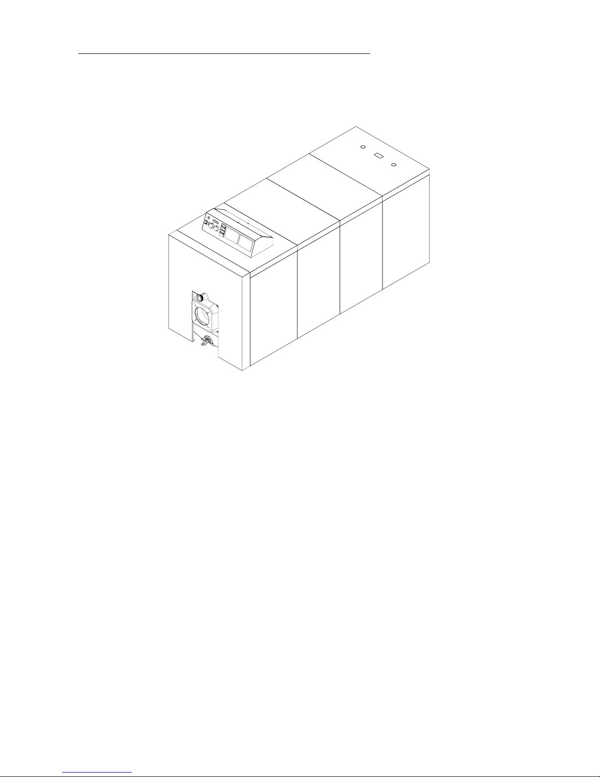
3.3.3. Assembled view
Commodore n° 5 & 6 (122 - 132)
Commodore n° 7 & 8 (241 - 242)
Page 17
Page 17 / 36
Hartley and Sugden
Commodore n° 9 & 10 (234 - 244)
Commodore n° 11 & 12 (335 - 345)
Page 18
Page 18 / 36
Hartley and Sugden
Commodore n° 13 & 14 (355 - 455)
Page 19
Page 19 / 36
Hartley and Sugden
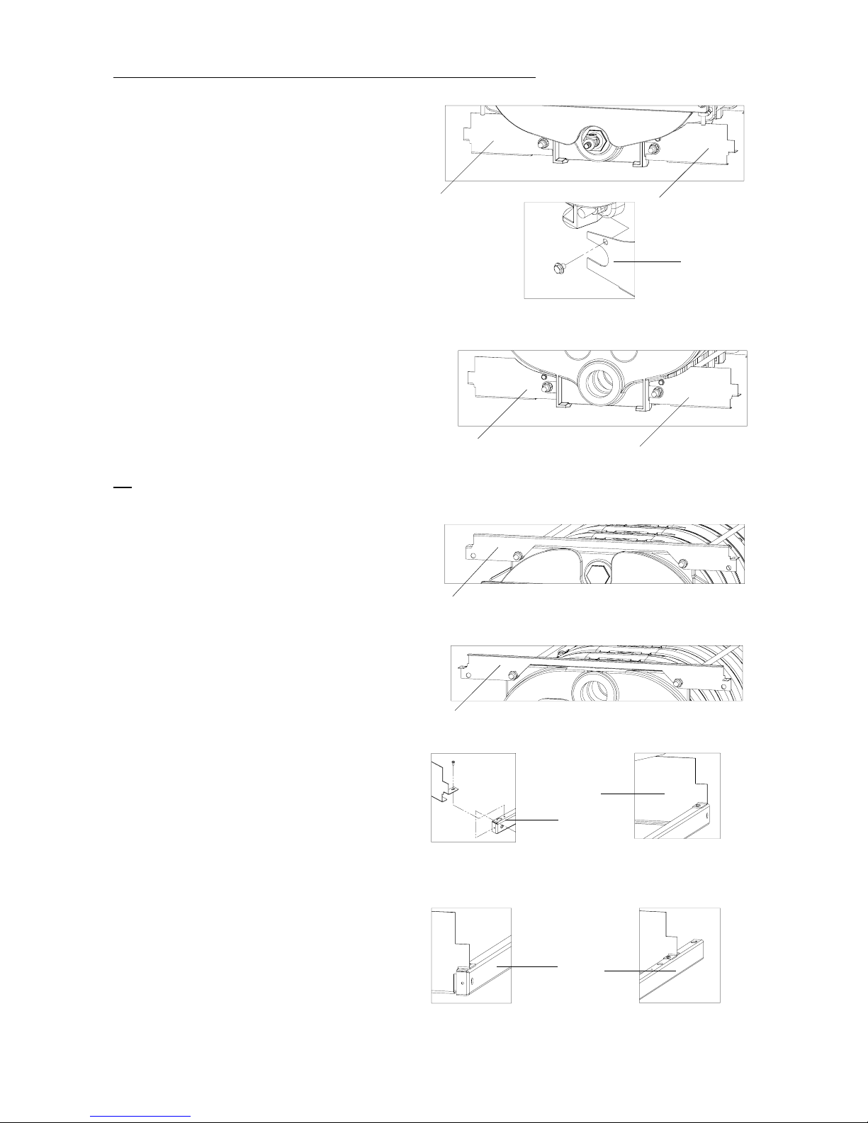
3.3.4. Assembly of the panels and plates
1. Fixing of the frontrightlower guide support onthe front cast-
iron section (fold backwards).
- 1 Tensilock screw M8X12
2
1
2. Fixing of the front left lower guide support on the fro nt
cast-iron section (fold backwards).
- 1 Tensilock screw M8X12
1
3. F ixing of the rear left lower guide support on therear cast-
iron sectio n (fold inside).
-1TensilockscrewM8X12
43
4. Fixing of the rear right lower guide support on the rear
cast-iron section (fold inside).
- 1 Tensilock screw M8X12
5
5. Fixing of the upper guide support o n the front cast-iron
section (fold backwards).
- 2 nuts M 16
-2washersM16
6. Fixing of the upper guide support on the rear cast-iron
section (fold backwards).
- 2 nuts M 16
-2washersM16
6
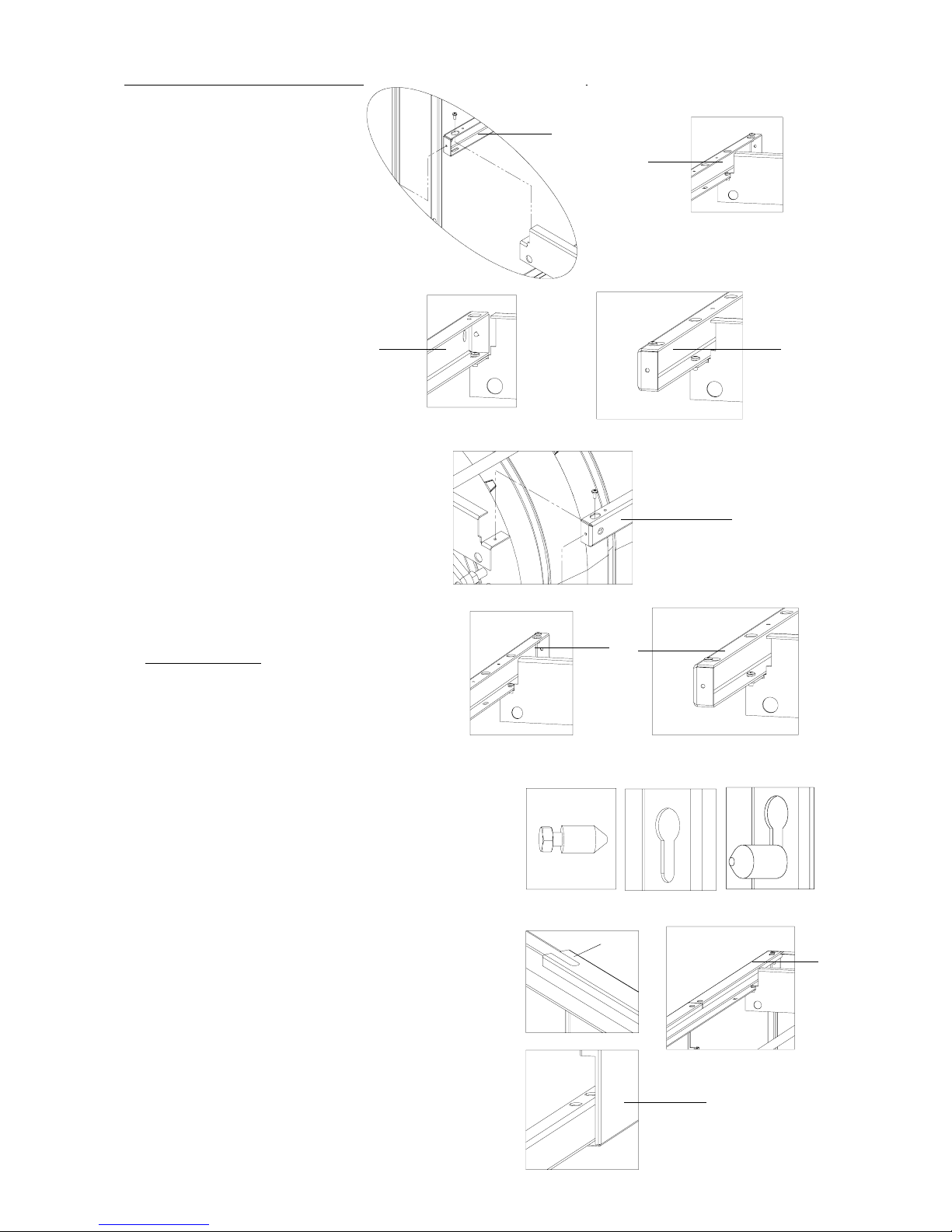
7. Fixing of the left lower guide.
- 2 Parker screws 4.2X10
8. Fixing of the right lower guide.
- 2 Parker screws 4.2X10
NB
: the front right lower guide supports are the same as the rear left.
the front left lower guide supports are the same as the rear right.
7
7
8
8
rear part
front part
rear part
front part
Page 20
Page 20 / 36
Hartley and Sugden
9. Fixing of the left upper guide.
- 2 Parker screws 4.2X10
10. Fixing of the right upper guide.
- 2 Parker screws 4.2X10
10 10
10
11. Placing of the set screw at the bottom of the
2 upper guides.
Screw only 2 times
- 2 Parker screws 4.2X10
12. Placing of the centering studs on the panels.
12.1.Screw the M4 screw on the centeri ng stud
(drawing A)(donotblock).
12.2. Insert the unit (stud external side) in the
oblong hole (drawing B),
Slip the unit in the back of the oblong and
tighten the thrust screw M4 (drawing C).
- from 4 to 12 centering studs Ø8X16 (M4)
according to model. 4 centering studs for the
Commodore Plus 5 & 6, 8 centering studs for the
Commodore Plus 7, 8, 9 & 10, 12 centering studs
for the Commodore Plus 11, 12, 13 & 14.
- from 4 to 12 thrust screws M4X6 according to
model. 4 thrust screws for the Commodore Pl us 5
& 6, 8 thrust screws for the Commodore Plus 7, 8,
9 & 10, 12 thrust screws for the Commodore Plus
11, 1 2, 13 & 14.
AB C
13. Encase the upper and lower slide from t he right rear panel
on the right lower and upper g uides and make slip this
one against the Parker screw 4 .2x10 fixed at the end of the
right guide.
(rear panel locatable thanks to the oblong hole on upper
edge detail A).
A
13
13
9
9
rear part
front part
front part
rear part
11
Page 21
Page 21 / 36
Hartley and Sugden
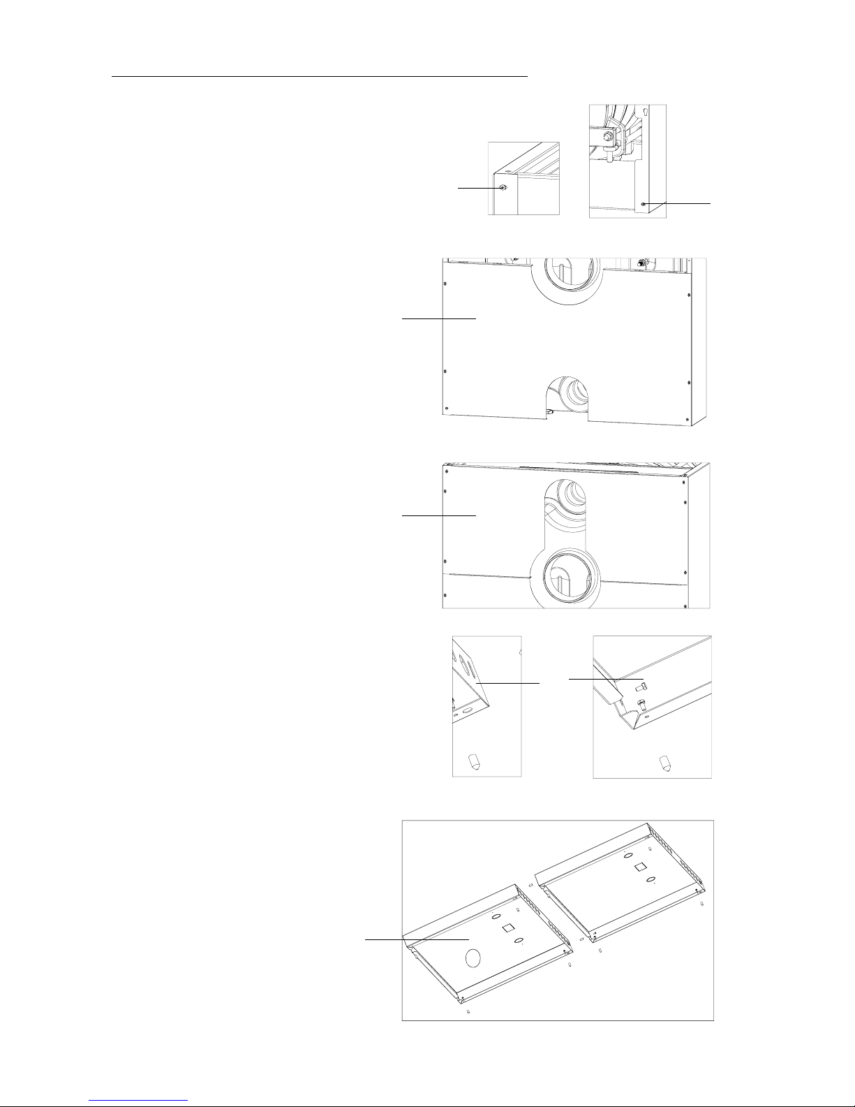
14. Proceed in the same way for the intermediate panel(s).
15. Proceed in the same way for the front panel.
16. Tighten the right front panel ahead on the lower and
upper guide
- 2 Parker screws 4.2X10
16
16
17. Place and screw the rear lower plate.
- 6 Parker screws 4.2X10
17
18. P lace and screw the rear upper plate.
- 6 Parker screws 4.2X10
18
19. Assembly of the centering studs on the covers.
- from 10 to 22 c enter ing studs Ø8X16 (M4) according
to model. 10 centering studs for the Commodore Plus
5 & 6, 16 centering studs for the Commodore Plus 7 ,
8, 9 & 10, 22 centering studs for the Commodore Plus
11, 12, 13 & 14.
- from10 to 22 thrustscrewsM4X6 accordingto model
10 thrust screws for the Commodore Plus 5 & 6,
16 thrust screws for the Commodore Plus 7, 8, 9 & 10,
22 thrust scr ews for the Commodore P lus 11, 12, 13 &
14.
19
20. Place the front cover (A).
20
front door rear door
A
Examplefor n° 122 (5 inter) - 132 (6)
Page 22
Page 22 / 36
Hartley and Sugden
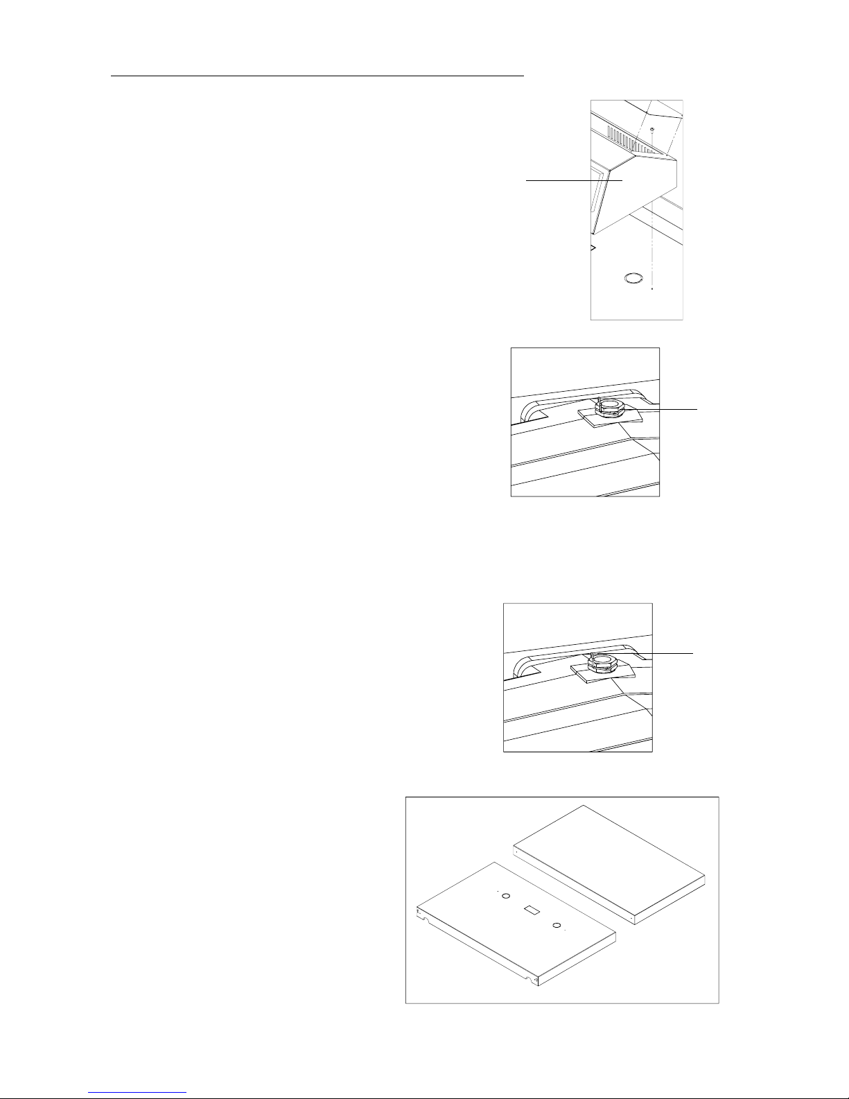
21. Fix the control panel on the front cover.
- 2 Parker screws 4.2X10
21
22. Placing of the sensors of the control panel in the p lunger
placed in the higher part of the rear element.
22
23. Placing of the rectangular panel for the sensors in the
plunger.
Rectangular panel for plunger 3/4"
24. Placing of the clips for plunger.
1 copper clips for plunger 3/4"
24
25. Placing of the intermediate covers and rear cover
according to model.
Page 23

Page 23 / 36
Hartley and Sugden
4. Hydraulic installation of the boiler
General points
The installer must provide a safety valve in the flow outlet prior to any valve or connection to any hydraulic appliance.
The installation must be designed in such a way that the filling and addition of water to the system takes place as infrequently
as possible and must always be strictly c ontrolled. Any uncontrolled automatic filling of the system is prohibited.
Should the boiler be connected to an existing heating installation, it is necessary to carry out a careful flushing of the system
in order to eliminateall impuritiesand sludgedeposit whichmaybe present. Such deposits, if allowed to remain could accumulate
in the boiler and cause overheating, corrosion and noises.
In order to avoid the complete emptying of the system (in the eventof problemsoccurring with the boiler or the heatingcircuit),
We recommend:
- the installation of isolating valves o n the boiler flow and return connectio ns.
- hydraulic insulation of one of several circulating pumps.
All necessary precautions must be taken to prevent :
- Gases accumulation in the top part of the boiler
- Deposits of sludge in the bottom part of the boiler.
Filling oftheinstallation
Prior to the final filling of the installation we recommend on both existing and new installations that the system is completely
flushed out and at the same time the water tightness of the system and hydraulic components verified.
The maximum hydraulic operating pressure is (4 bar ( 4kg/cm
2
). However, it may prove necessary to adapt the operating
pressure according to the characteristics of the installatio n, ci rculating pump an d pressure of the expansion tan k. With
nitrogen the cold installation pressure must ALWAYS be higher than the nitrogen pressure of the expansion tank.
During filling and when water is added to the system it will always be necessary to ve nt the air from the installation.
Significantadditions ofwater to the installatio n maybring about premature deterioration of the boiler witha deposit of mineral
substances present in the water. These depo sits lead to t hermal and mechanical constraints, which may go as far as resulting
in the cracking of the cast iron sections of the boiler.
Characteristics of the water in the heating circuit
In order to avoid all harmful furring-up and corrosion, one must take into account the characteristics of the water used in
the heating circuit.
The normal characteristics of the heating must be such that :
- the THF (calcium carbonate or fur-content of the water) is less than 25° THF (2,5 mol/m³)
- the resistivity is over 2,000 Ohm/cm.
Should the THF-value be over 25° THF, a softening treatment for the water of the heating circuit is necessary.
If the pH is lower than 7.2 and the resistivity is below 2,000 Ohm/cm and the THF-value is below 25° THF (either naturally or after softening), a treatment enabling these values to obtain or a treatment forming a film on the insides of the
heating installation should be used.
Furring-up and corrosion water side
In order to avoid all furring-up and corrosion water side, one must take into account the characteristics of the water used.
The installation will be designed in way that the fillings and additions of water be limited as possible and always controlable
(water meter recommended). Any system not controlled of automatic water filling is prohibited
. In all cases, a control of the
addition of water must be envisaged. The expansion vessels overflows must be perfectly visible.
If the conditions here above are not met, the frequent filling of the installation may involve deposits (scale deposits,
mud, ...) in the boiler a nd compromise its life duration.
Page 24
Page 24 / 36
Hartley and Sugden
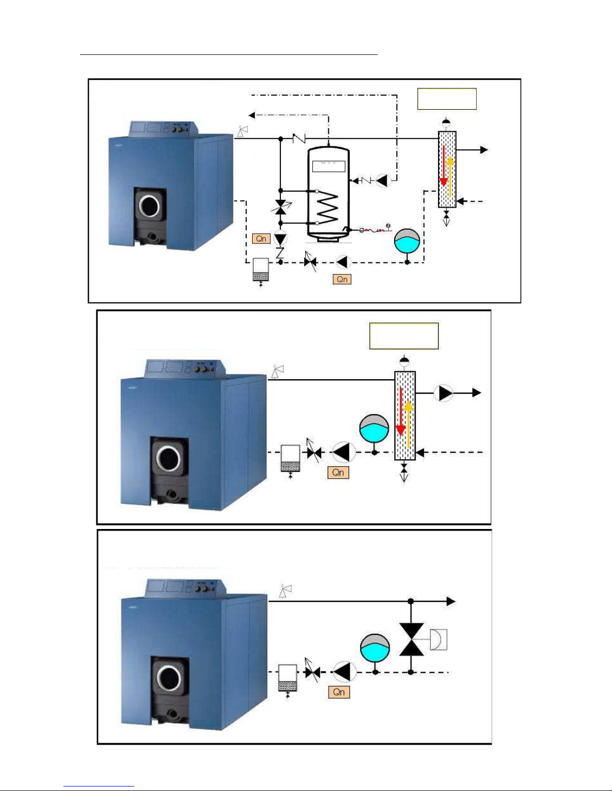
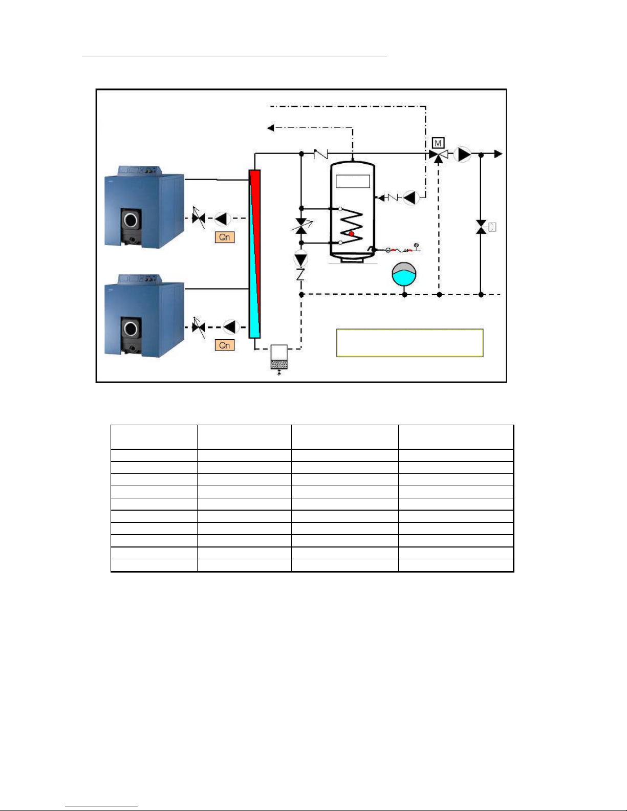
A. Example of individual boiler
common pipe
SWW
common pipe
Page 25
Page 25 / 36
Hartley and Sugden
Type
Nominal
outp ut (kW)
Flowǻ20 k (m³/h)
Recommended
c ommon pi pe
Commodore Plus 122 162 6,966 1-60-390-69952
Commodore Plus 132 204 8,772 1-60-390-69952
Commodore Plus 241 224 9,632 1-60-390-69952
Commodore Plus 242 253 10,879 1-60-390-69952
Commodore Plus 234 283 12,169 1-60-390-69952
Commodore Plus 244 310 13,33 1-60-390-69952
Commodore Plus 335 339 14,577 1-60-390-69952
Commodore Plus 345 371 15,953 1-60-390-69952
Commodore Plus 355 394,5 16,9635 1-60-390-69952
Commodore Plus 455 432 18,576 1-60-390-69952
B.Exampleof Ecogroup boiler application
Substantial savings can be made with Ecoset . These savings are obtained by splitting up the necessary output by regulating
to optimize the operation o f the e q uipment.
ECOSET presents following advantages :
- High p erformance
-Safeoperation
- Startup savings
- All-round installation p ossible
- Efficient and appropriate r e gulation
- Independant oper ation of each boiler in the s et
- Output adjusted to power demand
- Possibility of supplying different circuits at different tempe ratures by means of a loop at constant o r variable
temperature depending o n the outside temperat ur e.
SWW
ECOGROUP
Page 26

Page 26 / 36
Hartley and Sugden
5. Protection of chimneys agains internal condensations
The increase of boiler efficiency, the placing of an economy flap on the burners (stopping the admission of air when the
burner is stopped and hence the draft into the chimney), the oversize capacity of the chimneys in relation to the reduction
of the installed boiler yields, the influence of more powerful regulation de vices on the functioning time of the burners,
these are all parameters that necessitate the taking of certain precautions with a view to maximally reducing the risk of
condensation inside the chimney with the connection of high performance boiler to chimneys, in particular when this
involves existing chimneys.
Precautions to be taken :
1. Setting burner output acc ording t o the nominal yield of the furnace.
2. Provide a draught stabilizer of a size acc ording to the section of the chimney, that will:
a) during the periods when the burner is working, stabilize the draught, reduce the dew point temperature of the water
vapour by mixing of the combustion gases with ambient air.
b)during the period when t he burner is not working, ensure the ventilation of the chimney by ambient air (b y setting
the stabilizer t o be not completely closed when the bur ner is stopped ), which enables the remaining condensation
to be removed).
3. Avoid the application of heightening tubes on chimneys which cause excessive cooling of the combustion ga ses.
4. In thecase ofa markedlyoversized or particularly "cool" chimney (e.g. one situated nextto anexterior wall), youare advised
to prov ide an internal flue duct that must be placed according to the relevant technical prescriptions.
Page 27
Page 27 / 36
Hartley and Sugden
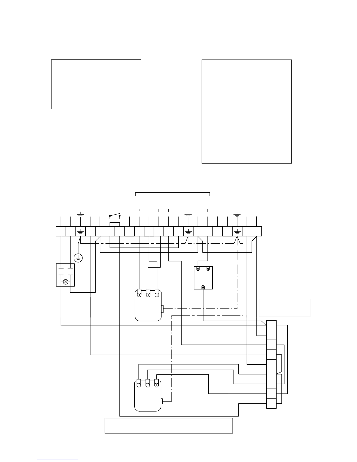
6. Electrical connections
Wiringdiagram :
The setting of the temperature on the
high/lowthermostat(f.i. 65°C) has to be
inferiorto that of the first step thermos-
tat(f.i. 80°C). Inthisway,if the boiler is
cold and if there is a heat demand, the
burner will start with its whole power
and once the 65°C reached, it will con-
tinue to burn with reduced power until
the water temperature of the flow rises
to 80°C. If the heat demand is to impor-
tant that the water temperature falls
down instead of reaching 80°C, than
the whole power will engage again.
Remark:
As far as Ecosets are concerned are the
electrical connections of the circulation
pump of the heating circuit made in the
control box outisde the boiler control
panel.
T6
T7
T8
T2 T1
N
L1
L
N
21P
21P
4
1
5
2
P
1
2
23456789
1
12 4567891011 15 2021
L
N
L
N
1612
B4
B5
17
S3
13 18
To burner
Safety limit
SP-051 HE
(110°C)
230V ca-50Hz
NT 174 HE/2
2
nd
step
thermostat
(30 - 90°C)
Power supply
switch
with phial
Circula tion pump
heating circuit
(not supplied)
Remote
thermostat
(not supplied)
Standard plug
with 3 poles
(not supplied)
Standard plug
with 7 poles
(not supplied)
Circula tion pump
water tank
(not supplied)
Remove the 4 bridges
when you connect a digital
regulator E9.0631
If you connect a regulator E9.0631, remove the bridge
between terminals 5 and 6 of the main connector block.
(*)
NT 174 HE/2
1
st
step
thermostat
(30 - 90°C)
Page 28
Page 28 / 36
Hartley and Sugden
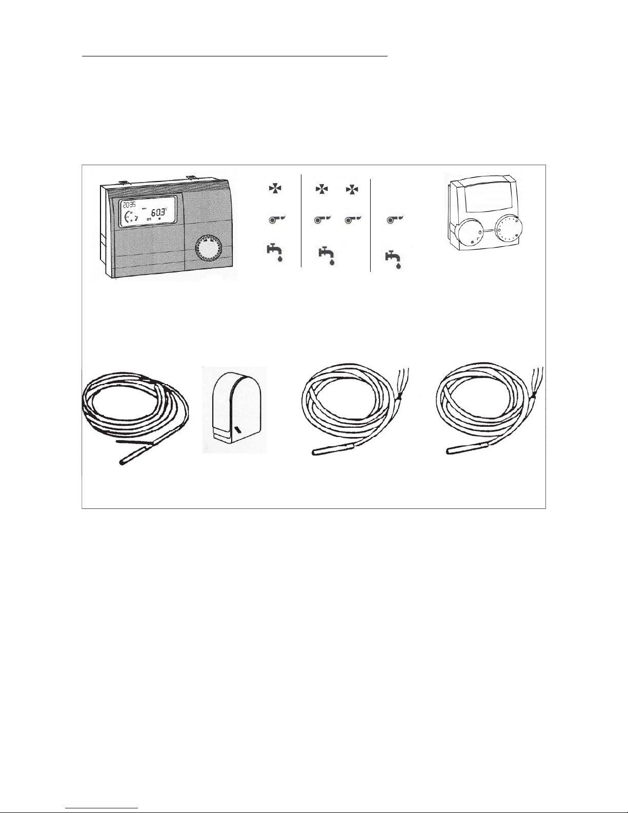
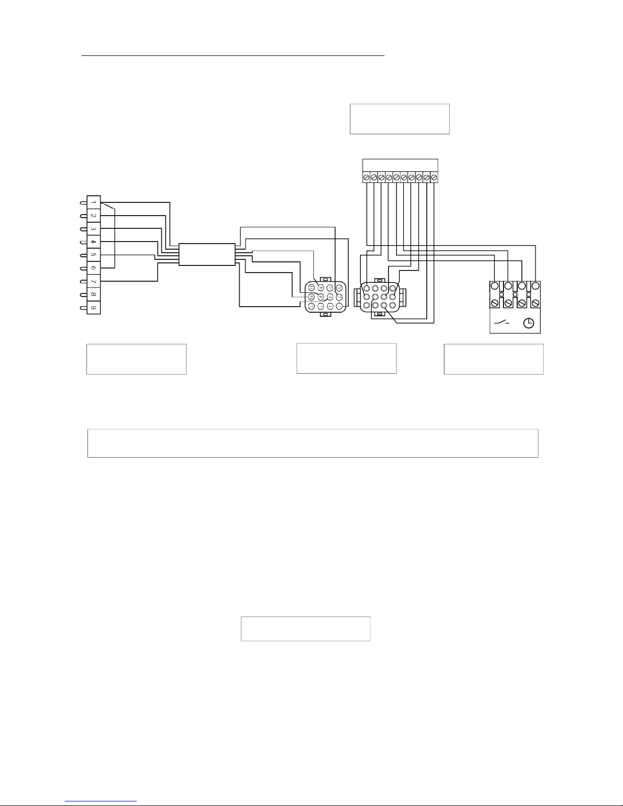
6.1. CONNECTION OF THE SAINT ROCH CLI MATIC REGULATOR
6.3.1. Components of climatic regulator HARTLEY & SUGDEN
E9.0300 E9.0631
GTCO
The control panel of theCommodore Plus boilersis prewiredto receiveone ofthe optionalclimatic regulators E9.0300, E9.0631,
GTC0 in place of the control panel precuts.
Climatic regulator
delivered in option
Remotecontrol FBR2
delivered in option
Tank probe SPFS
delivered with the
regulator
Boiler probe KFS
delivered with the
regulator
Departure probe VFAS
delivered with the
regulator
Externalprobe AFS
delivered with the
regulator
In order to install this regulation, it is necessary to interpose between the boiler connector block and the regulator, a
connection kitwired (9 poles) delivered with the r egulator accessories. The E9.0300 and E9.0631 climatic regulators maybe
associated in option to a remote control with an ambient thermoresistor type FBR 2 connected on the regulator using 3 wires.
Moreover, in the event of heating floor circuit, the regulator requires a valve servomotor SM 40 also available in option and
connected with 4 wires.
All components of the Hartley & Sugden control are easily accessible and the connections easy allowing a saving of time
appreciable fort the fitter.
Page 29
Page 29 / 36
Hartley and Sugden
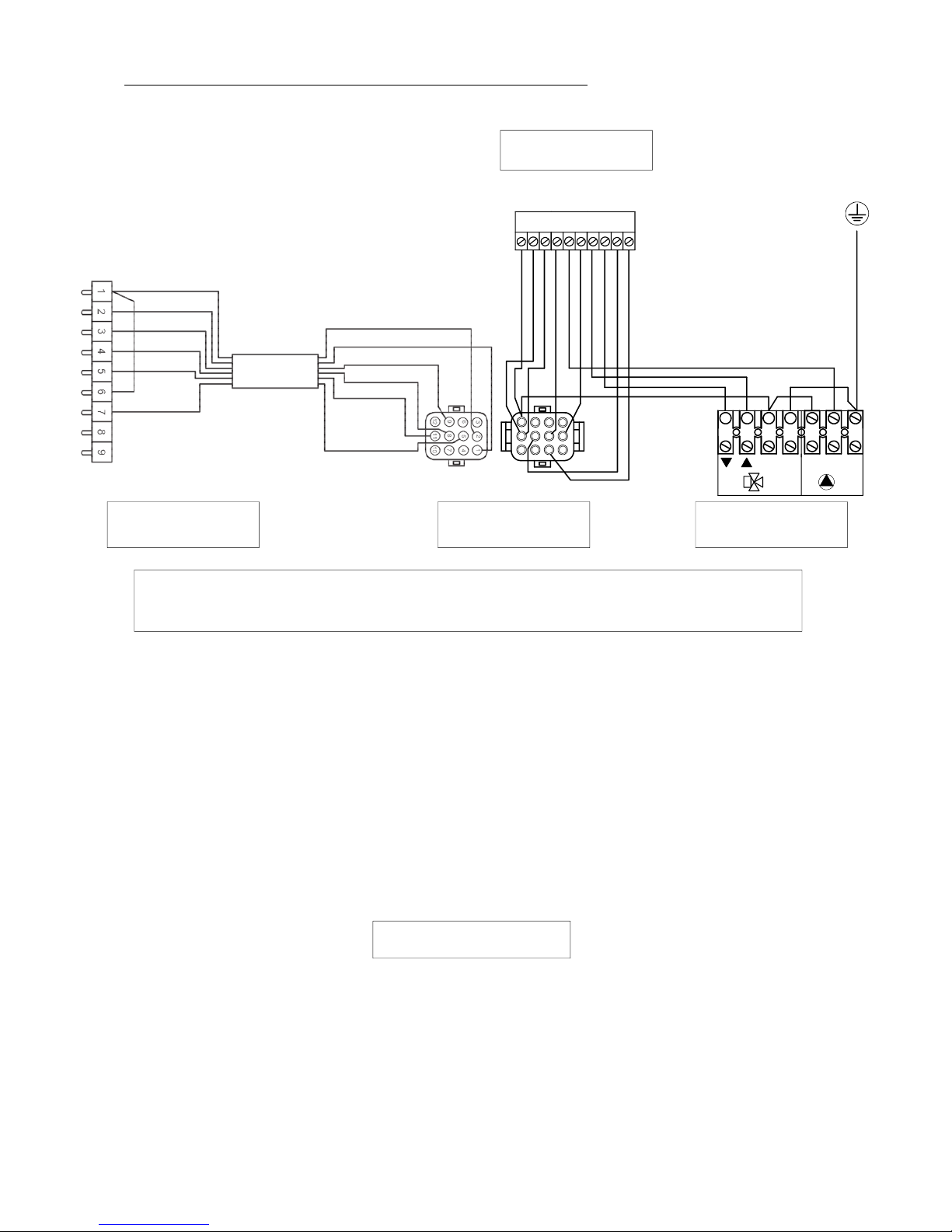
6.1 .2. Connectionkit of the regulator E9
II
1234
5678910
N
PENL1
PE
147
10
258
369
1112
ST 2
E9.0300 / E9.0631
GTC 2 / GTC 3
10-poles connector
regulator side
9-poles connector (A)
boiler side
AMP connector
12-poles (B)
circuit connector
2 controlled valve
CONNECTION OF THE E9.0300 / E9.0631 REGULATOR ON THE COMMODORE PLUS
BOILERS RANGE
1. Remove the right cap on the control panel and engage the regulator in this housing.
2. Remove the 9 poles male connector with its 4 bridges on the back of the control panel, or remove the S.W.W. priority
Ventec module already connected.
3. Connect the 9 poles connector (A) boiler side delivered with the regulator in the 9 poles female connector block
of the boiler and tighten the screws.
Connect the AMP 12 poles connector (B) delivered with the regulator in the AMP 12 poles plug of connector (A).
4. Connect the 10 poles white connector on the connector block II of the regulator.
5. Connect directly the following probes on the connector block I of the regulator.
-AFS :externalprobe
- KFS : boiler probe
- SPFS : S.W.W. probe
- VFAS : departure probe
6. Connect the heating circulator to terminals 8 and 9 and if necessary the S.W.W. circulator to terminals 11 and 12
on the boiler 12 poles connector block ( back of the control panel ).
GENERAL REMARKS
- do not connect the summer/ winter switch anymore, neither the S.W.W. tank thermostat, these functions being ensured
directlybythe E9.0300 / E9.0631 climaticregulator.
- place the boiler thermostat instruction at 80°C approximately.
Page 30
Page 30 / 36
Hartley and Sugden
6.1.3 . Connection kitGTCO regulator
II
1234
5678910
NL1
147
10
258
369
1112
ST 2
GTC 0
CONNECTION OF THE GTC0 REGULATOR ON THE COMMODORE PLUS BOILERS RANGE
1. Remove the right cap on the control panel and engage the regulator in this housing.
2. Remove the 9 poles male connector with its 4 bridges on the back of the control panel, or remove the S.W.W. priority
Ventec module already connected.
3. Connect the 9 poles connector (A) boiler side delivered with the regulator in the 9 poles female connector block
of the boiler and tighten the screws.
Connect the AMP 12 poles connector (B) delivered with the regulator in the AMP 12 poles plug of connector (A).
4. Connect the 10 poles white connector on the connector block II of the regulator.
5. Connect directly the following probes on the connector block I of the regulator.
- KFS : boiler probe
- SPFS : S.W.W. probe
6. Connect the heating circulator to terminals 8 and 9 and if necessary the S.W.W. circulator to terminals 11 and 12
on the boiler 12 poles connector block ( back of the control panel ).
GENERAL REMARKS
- do not connect the summer / winter switch anymore, neither the S.W. W. tank thermostat, these functions being ensured
directly by the GTC0 climatic regulator.
- place the boiler thermostat instruction at 80°C approximately.
Room
thermost at
10-poles connector
regulator side
9-poles connector (A)
boiler side
AMP connector
12-poles (B)
Page 31
Page 31 / 36
Hartley and Sugden
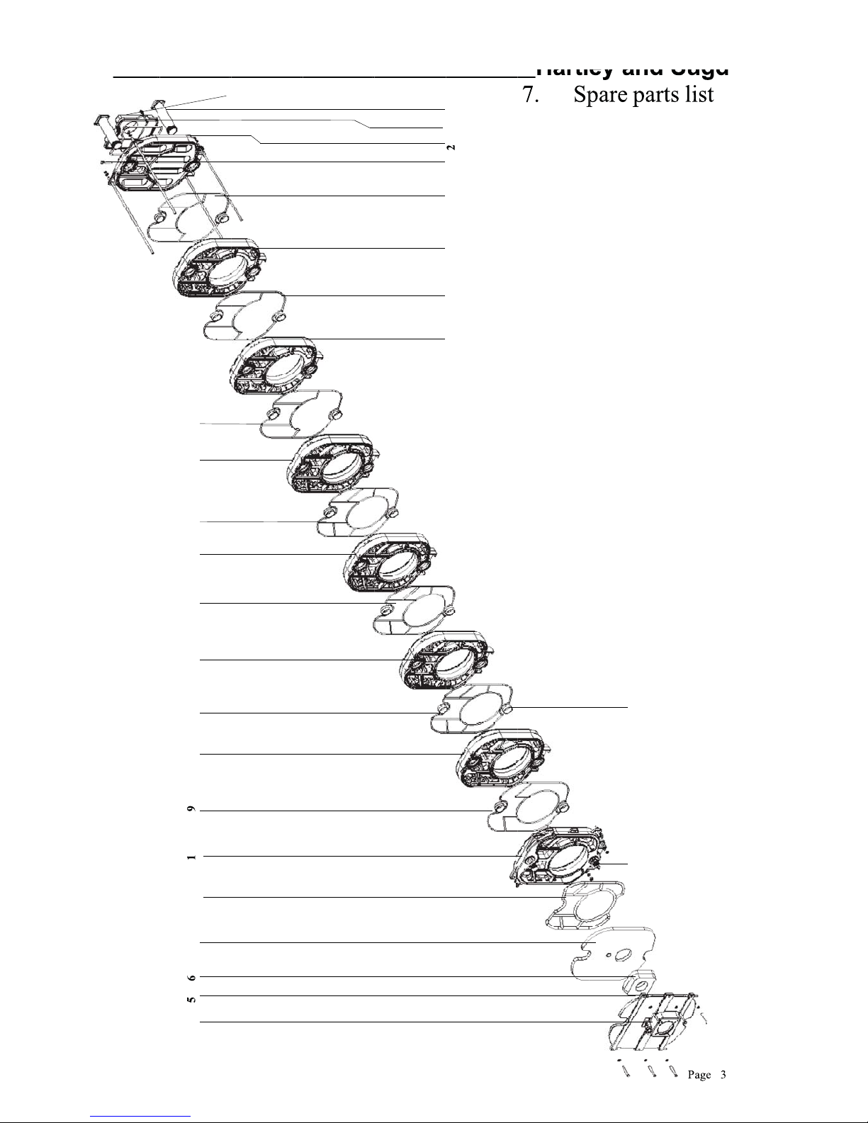
7. Spare parts list
2
9156
78 310 11
12
15
99119119
912 9
17
4
16
14
13
Page 32
Page 32 / 36
Hartley and Sugden
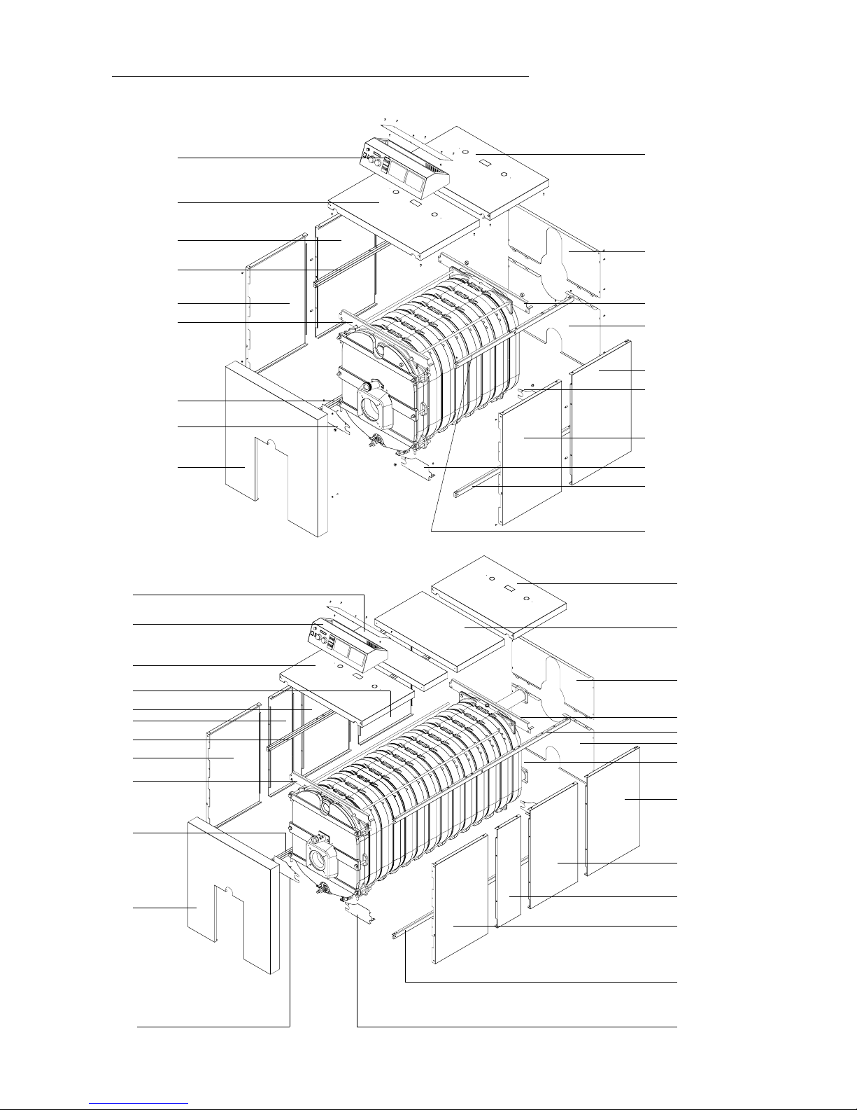
Casing Commodore Plus 5 - 6 (122 -132)
8
10
14
3
15
1
5
9
2
5
1
13
12
6
18
7
3behindthe
block
2
20
17
19
16
6
11
4
8
11
14
1
4
13
12
6
10
4
7
3
1
5
9
2
5
2
6
CasingCommodore Plus 11 - 12 (335 - 345)
Page 33
Page 33 / 36
Hartley and Sugden
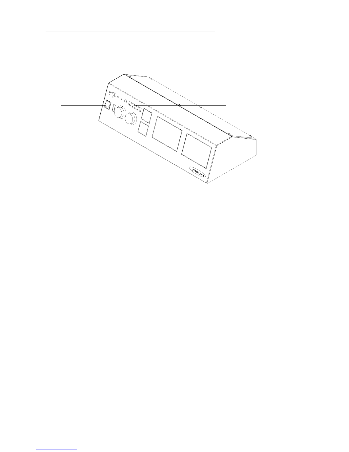
Controlpanel Commodore Plus
31 32
30
34
33 33
Page 34
Page 34 / 36
Hartley and Sugden
0-15-000-10005 1 boiler Commodore Plus 122 (5 inter)
0-15-000-10006 1 boiler Commodore Plus 132 (6 inter)
0-15-000-10007 1 boiler Commodore Plus 241 (7 inter)
0-15-000-10008 1 boiler Commodore Plus 242 (8 inter)
0-15-000-10009 1 boiler Commodore Plus 234 (9 inter)
0-15-000-10010 1 boiler Commodore Plus 244 (10 inter)
0-15-000-10011 1 boiler Commodore Plus 335 (11 inter)
0-15-000-10012 1 boiler Commodore Plus 345 (12 inter)
0-15-000-10013 1 boiler Commodore Plus 355 (13 inter)
0-15-000-10014 1 boiler Commodore Plus 455 (14 inter)
2-15-000-00000 1 Front element 1
2-15-000-01000 1 Rearelement 2
2-15 - 00 0 - 0 21 0 0 1 Front intermediate section Commodore Plus 122 -132 3
2-15-000-0 2100 2 Frontinterm. section Commodore Plus 241 - 242 - 234 - 244 3
2-15-000-0 2100 3 Frontinterm. sectionCommodorePlus 335 - 345- 355 3
2-15 - 00 0 -02100 4 Front interm. section Commodore Plus455 3
2-15-000-03000 1 Fluegas box 4
2-15-000-08100 1 Fuel naked door 5
1-30-310-00042 2 Front insulation furnace 6
1-30-310-20020 1 Door insulation 7
1-30-240-60120 1 Ceramic fibre rope Ø 20 mm siliconed 8
1-30-240-60410 acc.nr. Cord GPE Ø 10 mm 9
4-15-000-73000 1 Viewflame kit 10
1-30-380-90044 1 Pyrex view flame
2-15 - 000-022 00 2 Inter media temiddlesectionCommodorePlus 122 11
2-15 - 00 0 - 0 22 0 0 3 Intermediate middle section Commodore Plus 132 - 234 - 335 11
2-15-000-02200 4 Inte rm.middle section Commodore Plus 241 -242- 244 - 345 11
2-15 - 00 0 - 0 2200 5 Interm. middlesection Commodore Plus 355 - 455 11
2-15-000-02300 1 Intermediate rear section Commodore Plus 241 12
2-15 -0 0 0- 0 2 3 00 2 Intermediate rear section Commodore Plus 122 - 132- 242 12
2-15 - 00 0 - 0 23 0 0 4 Intermediaterear section Commodore Plus 234 -244 12
2-15-000-0 2300 5 Interm.rear section Commodore Plus 335 - 345- 355 - 455 12
1-60-700-10006 1 Drain cock 3/4" 1 3
1-70 - 64 0 - 3 41 0 1 1 Plunger3/4" - 100 14
3-99-000-02000 suiv. nr. Nipple 15
1-60 - 20 0 - 5 00 1 5 1 Pipe injector3" 70 mm Commodore Plus 242 16
1-60-200-5 0016 1 Pipeinjector3" 140 mmCommodore Plus 234 -244 - 335 1 6
1-60-200-5 0017 1 Pipeinjector3" 190 mmCommodore Plus 345 -355 - 455 1 6
1-30-240-60114 1 Ceramic fibre rope Ø 14 mm siliconed 17
Casing Commodore Plus
3-15-000-02000 2 Rear & front cover 1
3-15-000-08001 2 Upper rear & front fixation 2
3-15-000-08100 2 Right front & left rear fixation (lower) 3
3-15-000-08110 2 Left front & right rear fixation (lower) 4
3-15-000-30006 2 Stiffeningplate left upper and lower panel 122 - 132 5
3-15-000-30008 2 Stiffeningplate left upper and lower panel 241 - 242 5
3-15-000-30010 2 Stiffeningplate left upper and lower panel 234 - 244 5
3-15-000-30012 2 Stiffeningplate left upper and lower panel 335 - 345 5
3-15-000-30014 2 Stiffeningplate left upper and lower panel 355 - 455 5
3-15-000-31006 2 Stiffeningplate rightupper and lower panel122 - 132 6
3-15-000-31008 2 Stiffeningplate rightupper and lower panel241 - 242 6
3-15-000-31010 2 Stiffeningplate rightupper and lower panel234 - 244 6
3-15-000-31012 2 Stiffeningplate rightupper and lower panel335 - 345 6
3-15-000-31014 2 Stiffeningplate rightupper and lower panel355 - 455 6
3-15-000-01001 1 Right rear panel 7
3-15-000-00001 1 Left rear panel 8
3-15-000-00000 1 Left front panel 9
3-15-000-01000 1 Right front panel 10
3-15-000-03100 1 Front plate 11
3-15-000-04000 1 Rear lower plate 12
3-15-000-05000 1 Rear upper plate 13
5-15-000-11000 1 Control panel plate 14
Code article Quantity Description of parts Ref.
Page 35

Page 35 / 36
Hartley and Sugden
3-15 - 00 0 - 0 10 5 2 1 Rightinterm. panel 520mmCommodore Plus 335 - 345 1 8
3-15 - 00 0 - 0 00 5 2 1 Leftinterm. panel520mm Commodore Plus 335- 345 19
3-15 - 00 0 - 0 20 5 2 1 Interm.cover 520mm Commodore Plus 335 - 345 2 0
5-15- 00 0- 11 0 00 1 Wired control panel Commodore Plus 30
1-70-380-20122 1 Main switch On / Off 31
1-70-880-10120 1 Boilerthermometer 32
1-70-050-02120 1 Thermostat 1° an d 2° ste p NT 174 HE /2 33
1-70-050-01320 1 Safety limit with manual reset SP-051 HE 34
3-15-000-0 0026 1 Leftinterm. panel 260mm Comm. Plus 241 - 242 - 335 - 345 15
3-15-000-0 0052 1 Leftinterm. panel 520mm Comm. Plus 234 - 244 - 355 - 455 15
3-15-000-0 1026 1 Rightinterm. panel260mm Comm. Plus241 - 242-335 - 345 16
3-15-000-0 1052 1 Rightinterm. panel520mm Comm. Plus234 - 244-355 - 455 16
3-15-000-02026 1 Int erm.cover 260mmComm. Plus 241 - 242 - 335- 345 1 7
3-15-000-02052 1 Interm.cover 520mmComm. Plus 234- 244 - 355 455 17
Code article Quantity Description of parts Ref.
Page 36

Page 36 / 36
Hartley and Sugden
8. Maintenance
Maintenance must be carried out on the boiler once or twice a year, including an inspecti on of the cleanliness of the flue s.
Removecleaning cover (code n° 1-30-310-20010) andinsulation and thefurnace plate (code n° 4-20-020-44000) and insulation
(code n° 1-30-310-20010). Also remove the dividers (small and/or large models) and the stoppers, if fitted.
First, clean the horizontal flues then the vertical channels and finally the combustion chamber. The flue gas box has an
inspection cover (code n° 2-20-000-03100), allowing removal and collection of the soot during cleaning of the interior flues.
Abnormal fouling of the boiler may be caused by:
- incorrect burner setting
- obstruction of chimney
We recommend having the burner setting, the combustion characteristics and the good working order of the regulation
equipment verified every year by the installer.
If necessary, replace the insulation.
During re-assembly, replace the dividers and the stoppers (If necessary).
9. G uarantee conditions on the boilers
1. Our products are guaranteed against all manufacturing d efects insofar as they have been used in normal conditions and
have been installed and maintained in an approved manner, according to prevailing regulations and in accordance with
the requirements of our technical services.
Our technical instructions must be adhered to and annual maintenance be undertaken by a qualified person.
Our guarantee does not cover damage to boilers which have been used with polluted air including corrosive elements
such as chlorine, fluorine, sulphur etc. The use of water which is found to be unsuitable would also invalidate our
guarantee.
2. Our guarantee specified below commences on the date of delivery. Its duration being as follows :
- Cast iron block (i.e. the whole of the apparatus composing the block of the appliance) of the cast-iron
boilers : 2 years.
- All other accessories and pieces of equipment supplied with our boilers are subject to individual
manufacturers guarantee.
3. The guarantee is restricted to either the repairing or the simple replacement - at our discretion - of any component sent
to our registered office free of charge and which we recognize to be defective, with the exclusion of any labour costs,
transport or travelling expenses and any damages or compensation whatsoever.
4. T he replacement or repair of a component in the course of the period of guarantee will not result in the extension of this
period.
5. We will not accept any costs o n account of the installation, which is entirely the responsibility of the installer. Any visit
to site for any of the above reasons may be construed only as technical assistance and no way binding.
6. HARTLEY & SUGDEN reserves the right to modify the technical and aesthetic characteristics of its products without
notice.
7. The g uarantee is effective only if the guarantee card which accompanies the boilers is sent back by the user to
HARTLEYAND SUGDEN
ATLASWORKS,GIBBET STREET,
H
ALIFAX,WEST YORKSHIRE,
HX1 4DB
 Loading...