


Spectrum Scanner
User manual
No. UM0972150 R1-0
03/2014
English

User manual
UM0972150 R1-0
2
User Manual
Spectrum Scanner
Manual No. IM0972150, R1-0
Contents Page
1. Service menu 3
2. Spectrum Scanner menu 3
2. 1. Language 3
2. 2. RF settings 4
2. 2. 1. Video channel 4
2. 2. 2. Zigbee xmit power 4
2. 2. 3. Zigbee channel 4
2. 2. 4. Video RF band 4
2. 3. Power settings 4
2. 3. 1. Power mode 4
2. 3. 2. Heating setpoint 5
2. 4. OSD Settings 5
2. 4. 1. OSD Menu help 5
2. 4. 2. OSD Mode 5
2. 4. 3. OSD horizontal position 5
2. 4. 4. OSD vertical position 5
2. 4. 5. Debug mode on/off 5
2. 5. Setup Transmitter 5
3. Overview of menus 6
4. Version details 7
Introduction
Check with Orlaco which language versions are available. This
manual contains user instructions. Used photographs and
illustrations give general information and may differ from the
products you use.
Contact your Orlaco dealer if you have questions, additional
information, or want to make changes that are not described in this
manual.
The camera/display systems from Orlaco comply with the latest
CE, ADR, EMC and mirror-directive regulations. All products are
manufactured in accordance with the ISO 9001 quality management
system, ISO/TS16949 quality automotive and ISO 14001 environmental management systems.
For installation see Installation Manual IM0004060.
User manual
UM0972150 R1-0
3
Buttons 1 2 3 4 5 6 7 8
objects in
monitor are
closer than
they appear
C3
C2
C1
Figure 2
Figure 1
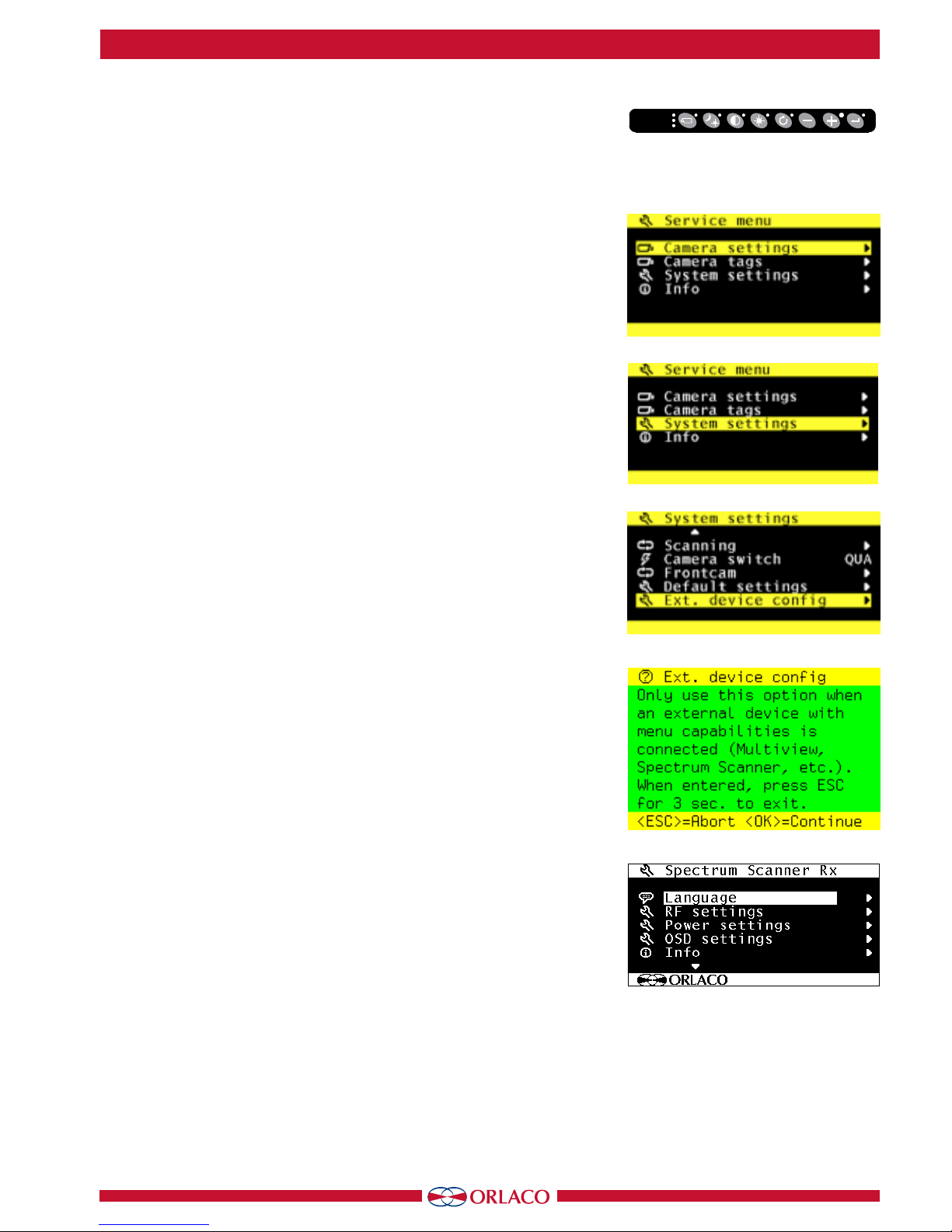
1. Service menu
Adjustment of the Spectrum scanner settings is done via the service
menu when an Orlaco Serial monitor is connected. To open the
service menu, simultaneously press the camera selection button
(1), the minus button (6) and the plus button (7) (see Figure 1).
The Monitor service menu (see Figure 2) will appear. The following
buttons are used to navigate through the menus:
5 - Option/previous menu: Return to the previous menu
6 - Minus: Go to the next menu option
7 - Plus: Go to the previous menu option
8 - Enter: Select or enable the chosen option
2. Spectrum Scanner Menu
There are settings in the Spectrum Scanner that can be adjusted.
We strongly advise not to change settings before consulting a
Orlaco service technician.
Open the service menu and go to system settings (see figure 3).
Select the Ext. Device Config (see figure 4).
A warning is shown in the monitor (see figure 5). Press enter to
continue.
The Spectrum Scanner Rx (Receiver) menu is shown (See figure 6).
The changes made here are done in the receiver of the Spectrum
Scanner.
If changes will be made, we advise to make the changes in the
transmitter first, see chapter 2. 5.
2.1. Language (see figure 6).
The OSD menu language is set as English by default. If you would
like to operate the OSD menu in a different language you can
change it. The OSD menu is available in English, Dutch, German,
French, Chech, Hungarian, Italian, Polish, Portuguese, Spanish,
Turkish, Swedish, Finnish, Danish and Norwegian.
Figure 3
Figure 4
Figure 5
Figure 6

User manual
UM0972150 R1-0
4
2. 2. RF settings (see figure 7)
In this menu the Receiver settings can be changed.
2. 2. 1. Video channel
With “video channel” the active video channel can be selected,
choice can be made from CH0 to CH7 and Auto. When a channel
is set, the spectrum scanner does not switch between channels. When “Auto” mode is selected the spectrum scanner will
switch to another channel when the quality of the connection is
no longer good enough. Make sure settings in the receiver and
transmitter are the same. Default setting is “Auto”.
2. 2. 2. Zigbee xmit power
This is the setting of the transmitting power of the data connection. Possible settings are 10, 12, 14, 16, 18 dB.
10dB ( 20mWatt) is the minimum and 18dB(60mWatt) the
maximum. Make sure settings in the receiver and transmitter are
the same. Default setting is 18dB.
2. 2. 3. Zigbee channel
The used channel for the data connection is in the 2,45Ghz bandwidth. Default setting is C19. If the channel is changed, make
sure to change the setting in the transmitter first (connection will
be lost) and after that the receiver.
2. 2. 4. Video RF band
Do not change this. Setting must be B-B.
2. 3. Power settings (see figure 9)
2. 3. 1. Power mode
The power mode is only used in the transmitter. There are three
setting possible (see figure 10):
AON = Always on.
SAV = Power save mode
30m = Switch of after 30 minutes when data connection is lost.
In AON mode the transmitter is always on and is powering the
camera at all time, even when there is no data connection.
This setting can be applied when the transmitter is powered with a
normal power connection.
In SAV mode the transmitter and power to the camera are switched
of when there has not been a data connection for 20 seconds.
In 30m mode the transmitter and power to the camera are switched
of when there has not been a data connection for 30 minutes.
This setting can be applied when a battery pack is connected. 30
minutes after the receiver is switched off, the transmitter is also
switching power off to the camera. Only data connection remains
active. As soon as data is received, the transmitter will start up.
Figure 7
Figure 8
Figure 9
Figure 10

User manual
UM0972150 R1-0
5
2. 3. 2. Heating setpoint (see figure 10)
With the build in heating the spectrum scanner will maintain the
internal temperature in the set value. Value to be set: OFF; -20°C;
-10°C; 0°C; +10°C; +20°C; +30°C; +40°C. Default setting is +10 °C.
2. 4. OSD Settings
In this menu the settings of the OSD of the Spectrum Scanner can
be adjusted. (See figure 11 and 12).
2. 4. 1. OSD Menu help
Activation of the pop up help information after 10 seconds.
2. 4. 2. OSD Mode
In this menu the selection of the shown information from the
transmitter in the monitor.
OFF
B+C: battery indicator and channel indicator are shown.
C+C: charge indicator and channel indicator are shown.
CHA: only channel indicator is shown.
Default setting is B+C, battery indicator and channel indicator
are shown.
2. 4. 3. OSD horizontal position
With this the position of the OSD can be horizontally adjusted to
place is in the middle of the screen.
2. 4. 4. OSD vertical position
Please do not change.
2. 4. 5. Debug mode on/off
This is a function that is used only when an Orlaco service technician is on site and test the equipment. Standard mode is OFF.
When in OSD mode the channel indicator is activated to be shown
in the monitor, the shown info gives info about the status of the
connections:
Capital letter “C” means the channel is set to a value.
Small letter “c” means the channel is set to auto.
Capital letter “H” means data communication is ok.
Small letter “h” means that there is no data connection.
cHx: automatic channel mode, data communication ok.
Chx: set channel, no data communication.
2. 5. Setup Transmitter
Now the Spectrum Scanner Tx (Transmitter) menu is shown (See
figure 13).
The changes made here are done in the transmitter of the Spectrum Scanner. The menu options are the same as described for the
Receiver
Figure 11
Figure 12
Figure 13

User manual
UM0972150 R1-0
6
Service menu
Camera- + Minus- and Plus buttons
Service menu
Camera settings
Camera tags
System settings
Info
System settings
Language
On screen display
Keyboard
Power settings
CAN-bus
LCD-Backlight
Scanning
Camera switch
Frontcam
Default settings
Ext. device config
CH0 to CH7, Aut
10d, 12d, 14d, 16d, 18d,
Default C19
Default B-B
Ext. device config
Language
RF settings
Power settings
OSD settings
Info
Setup transmitter
RF settings
Video channel
Zigbee xmit power
Zigbee channel
Video RF band
AON, SAV, 30m
OFFOFF; -20°C; -10°C; 0°C;
+10°C; +20°C; +30°C; +40°C
Power settings
Power mode
Heating setpoint
English, Dutch, German, French,
Chech, Hungarian, Italian, Polish, Portuguese, Spanish,
Turkish, Swedish, Finnish, Danish and Norwegian.
ON/OFF
OFF, B+C, C+C, CHA
Do NOT Touch
Default OFF
OSD settings
OSD menu help
OSD mode
OSD horizontal pos.
Debug mode on/off
3. Overview of menus

User manual
UM0972150 R1-0
7
4. Version details
1-0 First issue, March 2014

ORLACO
Orlaco is a Manufacturing company that specializes in making cameras and
monitor systems for commercial vehicles, fork-lift trucks, cranes, off shore
and maritime.
Our objective is to design and produce camera systems for the professional
market that improve the drivers’ view and increase operating efficiency.
A
t our facility in Barneveld we locate our design, manufacturing, warehousing
and service department.
Vision is our mission. Orlaco therefore deploys the development, manufacture,
supply and service of camera and display systems that will improve safety
and efficiency of all vehicles, machinery and vessels. Our systems give the
end user a view on each blind spot and will create comfort and improved
working conditions. Our active approach will support market demands and
innovations and will lead to enthusiastic ambassadors in the market; our
customers.
 Loading...