


ORLACO
Orlaco is a Manufacturing company that specializes in making cameras and
monitor systems for commercial vehicles, fork-lift trucks, cranes, off shore
and maritime.
Our objective is to design and produce camera systems for the professional
market that improve the drivers view and increase operating efficiency.
At our factory in Barneveld, we have a production department, warehouse,
design department, service department and showroom.
Vision is our mission®, and Orlaco therefore deploys the development,
manufacture, supply and service of camera and display systems that will
improve safety and efficiency of all vehicles, machinery and vessels. Our
systems give the end user a view on each blind spot and create comfort
and improved working conditions. Our active approach will support market
demands and innovations and will lead to enthusiastic ambassadors in the
market; our Customers.
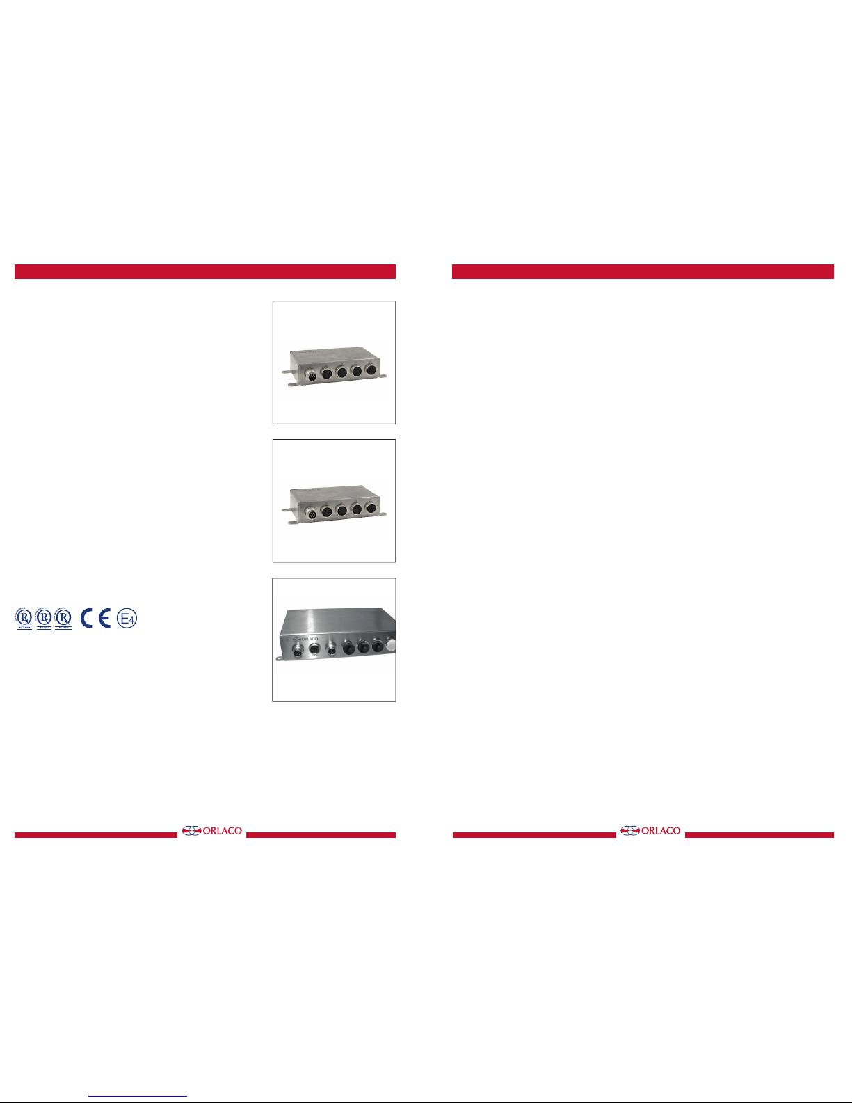
Multiview box II
Art no. 0405100
Multiview box II Serial
Art no. 0405110
Quad box II 4cam in 1 mon out
Art no. 0405300
Quad box II 1+3cam in 1 mon out
Art no. 0405310
User Manual
No. UM0972191 A 02
08/2016
English
Art no. 0405100
Art no. 0405110
Art no. 0405300/0405310
2
UM0972191 A 02
Multiview box II
Art no. 0405100
Multiview box II Serial
Art no. 0405110
Quad box II 4cam in 1 mon out
Art no. 0405300
Quad box II 1+3cam in 1 mon out
Art no. 0405310
Manual no. UM0972191 A 02
Introduction
Check with Orlaco which language versions are available. This manual
contains user instructions. Used photographs and illustrations give general
information and may differ from the products you use.
Contact your Orlaco dealer if you have questions, additional information, or
want to make changes that are not described in this manual.
All data subject to change without notice. All dimensions are for commercial
purpose only. The camera/display systems from Orlaco comply with the
latest CE, ADR, EMC and mirror-directive regulations, where applicable.
All products are manufactured in accordance with the ISO 9001 quality
management system, ISO/TS 16949 quality automotive, ISO 14001
environmental management systems, where applicable.
Contents page
1. Introducing 3
2. Quad Servive Menu 3
3. Channel mode 3
4. Camera settings 4
5. Startup mode 5
6. Camera tags 5
7. Advanced settings 6
8. Info 8
9. Channel mode overview 9
10. Version details 10
For speci cations see Data sheets
DS0963010-0405100 Multiview box II
DS0963020-0405110 Multiview box II Serial
DS0963080-0405300 Quad box II 4cam in 1 mon out
DS0963081-0405310 Quad box II 1+3cam in 1 mon out
User manual
Art no. 0405100
Art no. 0405110
Art no. 0405300/0405310
1111
UM0972191 A 02
User manual

10
UM0972191 A 02
10. Version details
Version R1-0. First issue, 8/2016.
Version A 01. Art. no. 0405310 added, 4/2017.
Version A 02. Figure 3, page 3 changed, 8/2017.
User manual
33
UM0972191 A 02
Choose how the camera views should be shown.
See figure 3.
NOR-mode: full view
ALL-mode: all view
DUA-mode: dual view
TRI-mode: 1-2 top view
REA-mode: 3-1 bottom view
D+R-mode: dual inset top view
SU 1 mode: surround view 1
SU 2 mode: surround view 2
1. Introducing
This user manual describes the Orlaco Multiview box II
and Quadbox II. Those are video view systems for up to
4 cameras PAL or NTSC.
Note: Use only PAL or NTSC cameras. You can not
connect both PAL
and
NTSC cameras in one system
together.
There are many possibilities of different split views in
5 selectable video channels. After the easy installations
you’ve got an advanced video viewing image for various
camera-system configurations.
2. Quad Service menu
Please first refer to the Orlaco Monitor User Manual for
operating using and the external device configuration
(Ext. device config) selection.
When the Ext. device config is selected you will see the
Quad Service menu, see figure 1.
Note: To exit the Quad Service menu, press de Option
button for 3 seconds.
The ‘Quad Service’ menu offers the following possibilities: Channel mode, Camera settings, Camera
tags, Startup mode, Advanced settings and Info. The
following chapters will explain these possibilities.
3. Channel mode
The Orlaco Quad has five camera channels. For the first
four channels you can select a default image layout or
a customer image (chapter 6) layout. Channel five is
always the quad layout, see figure 3.
Refer to chapter 9 for a complete overview
Showing the channels: Press the camera button to
switch between the channels.
User manual
Options for channel 1-4:
Default channel 5:
NOR ALL DUA
TRI
QUAD
REA D+R
1112
12
1122
2
3
3
3
SU1 SU2
14212
4
33
12
4
3
4
Figure 1
Figure 2
Figure 3
Please refer to chapter 7 ‘Advanced settings’ for customize your channel mode.
4
UM0972191 A 02
4. Camera settings
This section describes image, tag and marker options.
Note: The camera settings that have already been
set from the monitor will be mixed by the camera
settings which are set in the Multiview box II.
The ‘Camera settings’ menu offers the following possibilities for each camera (C1-C4), see figure 4.
Mirror
Enable this option to mirror the image (left/right)
Upside down
This option reverses the image (flips it upside down)
Tag hor. pos
Adjust the horizontal position of the tag.
(adjustable between 0-100)
Tag ver. pos
Adjust the vertical position of the tag.
(adjustable between 0-100)
Tag color
Select the color in which the tag should be shown;
(Black, Blue, White, Yellow, Magenta, Red, Cyan and
Green).
Hor. marker1
Enable this option to switch the marker on. The
marker is displayed as a horizontal default green (color
adjustable) line.
Marker pos.
Adjust the horizontal position of the marker. 0 is the
top of the screen, 100 is the bottom of the screen.
Marker col.
Adjust the color of the marker. Adjustable options:
GRN: Green BLU: Blue
MAG: Magenta BLA: Black
RED: Red WHI: White
YEL: Yellow CYA: Cyaan
Marker mix
Adjust the transparancy of the marker.
(adjustable options: 0-, 25-, 50- or 100%)
Hor. marker2
Enable this option to switch a second marker on. The
marker is displayed as a horizontal default green (color
adjustable) line.
The marker options are the same as the Hor. marker1.
Marker pos.
Adjust the horizontal position of the marker. 0 is the
top of the screen, 100 is the bottom of the screen.
Marker col.
Adjust the color of the marker. Adjustable options:
GRN: Green BLU: Blue
MAG: Magenta BLA: Black
RED: Red WHI: White
YEL: Yellow CYA: Cyaan
User manual
Figure 4
Figure 5
Figure 6
Figure 6a
99
UM0972191 A 02
9. Channel mode overview
12
2
3
34
4
1
1243
Channel 1
Channel 2 Channel 3
Channel 4 Channel 5
(quad-mode)
>>
>
OR
ode
ALL
mode
DUA
mode
TRI
mode
REA
mode
D+R
mode
SU1
mode
SU2
mode
1 2 3 4
1
2
4
3
12
4
3
12
4
3
12
4
3
12
4
3
12
4
3
12
4
3
12
4
3
1
1
1
2
3
4
2
3
4
3
2
4
4
2
3
12323434141
2
12 23 34 4
1
123
234 341
41
2
1
4
23
2314
2
1
34
3421
3
2
41
4132
4
3
12
>>
User manual

8
UM0972191 A 02
7.8. Boundary settings
See figure 24
Boundary on/off;
Turn boundary around video channel on or off.
Boundary color;
Adjust the color of the boundary. Adjustable options:
GRN: Green BLU: Blue
MAG: Magenta BLA: Black
RED: Red WHI: White
YEL: Yellow CYA: Cyaan
Boundary blink;
Choose wether the boundary should blink or not.
Boundary blink color;
Adjust the color of the boundary blink. Adjustable
options:
GRN: Green BLU: Blue
MAG: Magenta BLA: Black
RED: Red WHI: White
YEL: Yellow CYA: Cyaan
8. Info
See figure 25. This option shows Orlaco Multiview box II
information. Check in this screen your software version
which is described in this manual.
User manual
Sequencer power up; Select wether the sequencer
starts in auto or manual mode after power-up.
Manual mode is only function in other (special)
products from Orlaco and can not be selected in this
con guration.
7.6. Comm. settings
See figure 22
These settings are for internal Orlaco use only and
have no function with the orlaco Serial monitor.
Please do not change the settings.
7.7. OSD settings
See figure 23
Menu horizontal pos
Adjust the horizontal position of the menu. 1 is left up
and 16 is right up.
Menu vertical pos
Adjust the vertical position of the menu. 1 is top of
screen and 8 is bottom.
Figure 24
Figure 25
Figure 22
Figure 23
Figure 21
55
UM0972191 A 02
Marker mix
Adjust the transparancy of the marker.
(adjustable options: 0-, 25-, 50- or 100%)
Ver. marker1
Enable this option to switch the marker on. The marker
is displayed as a vertical green (color adjustable) line.
The marker options are the same as the Hor. marker1.
Ver. marker2
Enable this option to switch a second vertical marker
on. The marker is displayed as a green (color adjustable) line.
The marker options are the same as the Hor. marker2.
Brightness
Adjust the brightness of the image
(adjustable between 0-100)
Contrast
Adjust the contrast of the image.
(adjustable between 0-100)
Saturation
Adjust the saturation (color intensity) of the image.
(adjustable between 0-100)
5. Startup mode
Choose the default output video mode (PAL, NTSC)
when no camera is attached. See figure 8.
6. Camera tags
This section describes how to define the camera textlabels, see figure 9.
In this menu the text-labels for the camera inputs can
be defined.
The number of the tags is depending on the camera
switch option. (For more info please refer to the Orlaco
Monitor User Manual.)
Select a camera and the option opens the camera tag
editor menu. You can define each camera a name. (max.
6 characters), see figure 10
User manual
Figure 9
Figure 10
Figure 7
Figure 8

6
UM0972191 A 02
7. Advanced settings
Note: This option shows a menu of settings that
rarely need adjustment and are better left to quali ed
technicians.
This chapter describes the advanced settings of language
selection, factory default resetting, channel settings,
Switchwire settings, Communication settings, Sequencer
settings, Communications settings, OSD settings and
boundary settings, see figures 11 and 12.
7.1. Language
This option opens the language selection menu. See
figure 13. The selected language will be used for all OSD
menus. The OSD menu is available in English, Dutch,
German, French, Czech, Hungarian, Italian, Polish,
Portuguese, Spanish, Turkish, Swedish, Finnish, Danish
and Norwegian.
7.2. Default settings
Select defaults
See figure 14. This option opens the factory defaults
menu. Choose the number of the desired factory settings (11 default settings, 1 = standard Orlaco).
Restore defaults
See figure 14. If the option ‘restore defaults’ is selected, the factory settings will be reset. Warning: All user
settings will be lost when factory defaults are reset.
7.3. Channel settings
The channel settings can be modified. Per channel (CH1CH9) you can choose a window (W1-W4 and define per
window which camera (C1-C4) is shown, see figures
15, 16.
W1 on/off
When enabled the window is displayed.
W1 Camera
Select here which camera (C1-C4) should be shown in
this window.
W1 priority
Select the window priority, see figure 17.
LOW: lower window
NOR: middle window
HI: upper window
Note: There’s only one priority high- and one priority
low possible. Make sure that the priority normals do
not overlap each other.
User manual
Figure 14
Figure 15
Figure 16
Figure 13
Figure 11
Figure 12
77
UM0972191 A 02
W1 hor. pos.
Determine the window top left horizontal position.
(adjustable between 0-100)
W1 ver. pos.
Determine the window top left vertical position.
(adjustable between 0-100)
7.4. Switchwire settings
See figure 19.
These settings are used in other (special) products
from Orlaco and have no function in this con guration. Please do not change the settings.
7.5. Sequencer settings
See figures 20, 21.
Auto seqeuncer mode; select how the sequencer will
step through the channels when running in automatic
mode. OFF/FWDforward)/BWD(backward).
Set sequencer timer; Set the sequencer interval time
from 0,5 to 5 seconds
Auto sequence range; Set the range of channels that
the sequencer will use when in automatic mode. 1-2
to 1-9.
Sequence skip blank; When checked, the automatic
sequencer will skip channels where the window 1 has
no video signal.
Man sequence range; Set the range of channels that
the sequencer will use when in manual mode. 1-2 to
1-9.
Sequence skip blank; when checked, the manual controlled sequencer will skip channels where the window
1 has no video signal
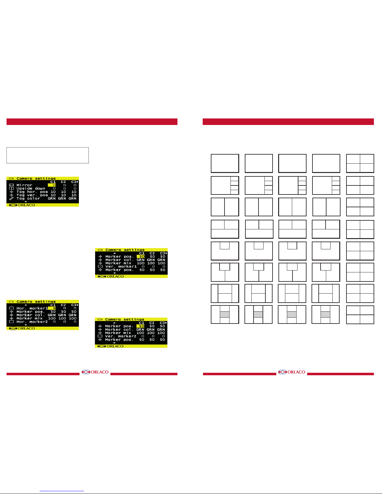
W1 size
Select the size of the window, see figure 18.
Adjustable options:
Fig. A. 1/1, 3/4, 2/3, 1/2, 1/3, 1/4, 1/5, 1/6, 3/4, 2/3, 1/2.
Fig. B. 34W, 23W, 12W, 13W, 14W, 15W, 16W.
Fig. C. 34H, 12H, 13H, 14H, 15H, 16H.
User manual
Figure 17
Figure 19
Figure 20
Figure 18A
Figure 18B
Figure 18C
1/6
1/5
1/4
1/3
1/2
2/3
3/4
1/1
16W
15W
14W
13W
12W
23W
34W
1/1
16H
15H
14H
13H
23H
12H
34H
1/1
 Loading...