

Orlaco 0506911, 0516911, 0506952, 0516951, 0516961 Installation Manual
...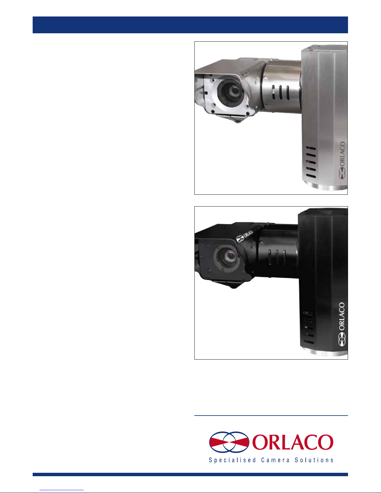
Camera PTZ
PAL/NTSC Alu/SSt
Installation Manual
Manual No. IM0973142, R1-4
Article no. 0506911, 0516911
0506952, 0516951
0506961, 0516961
09/2014
English
Article no. 0506952; Camera PTZ PAL Alu
0516951; Camera PTZ PAL Alu RS485
0506961; Camera PTZ NTSC Alu
0516961; Camera PTZ NTSC Alu RS485
Article no. 0506911; Camera PTZ PAL Sst
0516911; Camera PTZ PAL Sst RS485
2 IM0973142 R1-4 IM0973142 R1-4 3
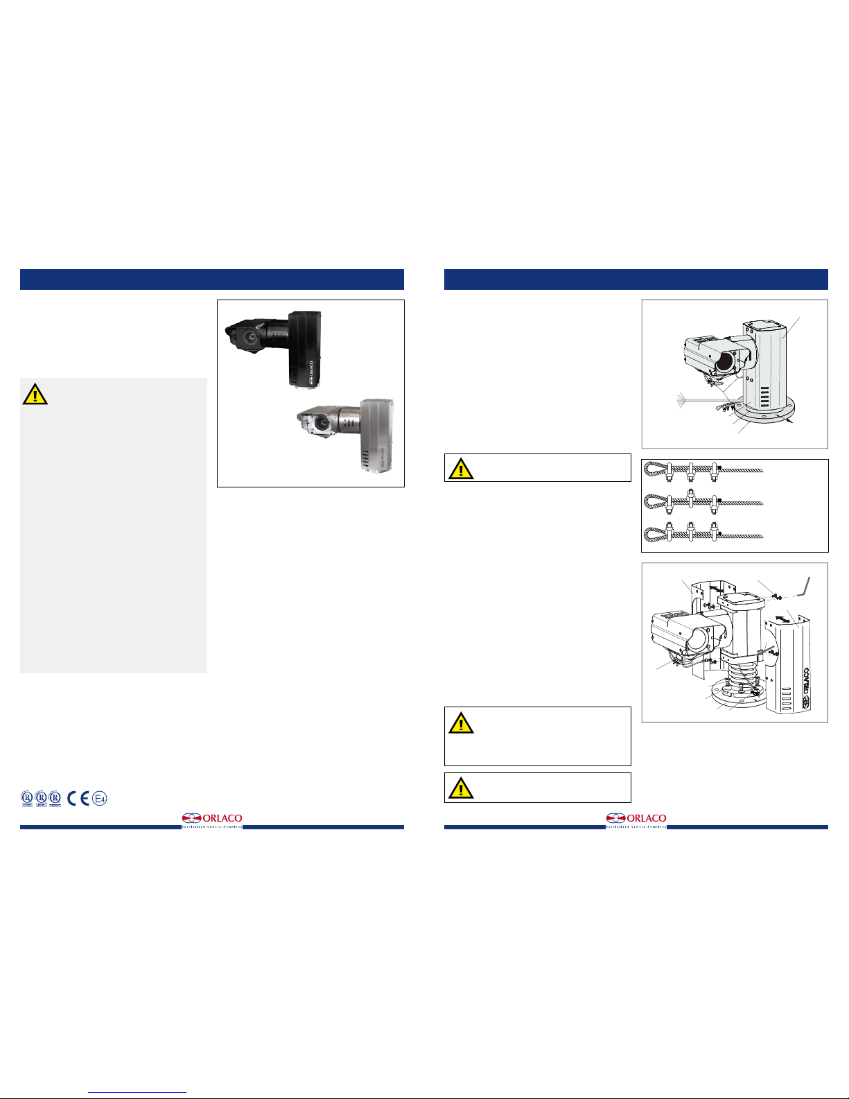
CORRECT
INCORRECT
INCORRECT
U-Bolt of all clips on
dead end of rope
Staggered clips
U-Bolt of all clips on
live end of rope
Installation Manual
Camera PTZ PAL/NTSC Alu/SSt
Article no. 0506911; Camera PTZ PAL Sst
Article no. 0516911; Camera PTZ PAL Sst RS485
Article no. 0506952; Camera PTZ PAL Alu
Article no. 0516951; Camera PTZ PAL Alu RS485
Article no. 0506961; Camera PTZ NTSC Alu
Article no. 0516961; Camera PTZ NTSC Alu RS485
Safety
In order to guarantee safe operation, these safety instructions must be read before you start using this equipment.
• Do not open the enclosure. The camera and the P&T enclosure are
pressurised. This can cause damage, short-circuiting or electrical
shocks.
• Do not expose the equipment to extreme temperatures. This can cause
deformation of the enclosure or damage to internal components.
• Repairs or adjustments to the equipment may only be undertaken by
Orlaco.
• The equipment must be assembled as shown in this manual.
• If there have been alterations or changes to this equipment that have
not been specifically approved by Orlaco, use of this equipment is not
permitted.
Statement related to Machine-directive 2006/42/EC:
Orlaco, under it’s role as manufacturers product-responsibility has
studied the impact of the Machine Directive onto the design of this
Pan/Tilt unit. We can make the following statement:
There is no risk that we aware of in the PTZ that is in conflict with the
Machine Directive and this device is safe to use under 2006/42/EC
machinery directive. :
2 safety measurements are in place to comply to the rules set out in the
directive:
1. Holes that are big enough to allow bodyparts in (see directive
for definition) are designed in a way that they cannot and will not
pinch the body-parts in normal operation of the PTZ as described
in this manual.
2. In the rare occasion that the device is hitting or pinching a
mechanical part or bodypart the electronics and integrated
sensors makes sure the stepping motors are stopped
automatically to prevent any damage similar to the way car
windows are functioning.
Before you start using this equipment, please read this manual carefully
and follow all instructions. This installation manual describes the functions of the equipment, outlines the connection options and explains how
to put the equipment into operation. We recommend that you keep this
manual in a safe place for reference purposes.
If you have any questions or issues concerning the operation of this
equipment, consult the relevant section in the manual or contact the
Orlaco Products BV Service department.
The camera and monitor systems from Orlaco comply with the latest CE,
ADR, EMC and mirror-directive regulations. All products are manufactured in accordance with the ISO 9001 quality management, ISO/TS16949
quality automotive and ISO 14001 environmental management.
Installation Manual
1. Introduction
PTZ (Pan Tilt Zoomcamera) unit.
Pan & Tilt unit including camera. The PTZ unit functions via two stepper
motors. These stepper motors are controlled by the integrated microcontroller and input commands RS232 RS485/Visca-, Pelco D protocol/P
9600 Baud rate. Commands for the PTZ unit are sent via, amongst other
things, the Monitor 7” RLED Serial or Monitor 12” Serial. Weather-,
shock-, vibration-, corrosionproof.
2. Configuration
The space required for panning and tilting is:
Panning: 315mm.
Tilting: 370mm.
See also figure 10, page 7. When positioning the PTZ unit, account must
be taken of the space required for panning and tilting. There must be no
obstacles in this space.
3. Mounting
The PTZ unit has a base. Mount the PTZ unit upright.
The PTZ unit may not be mounted hanging or at a right
angle! This would put too much pressure on the base
and mechanical components.
First demount two coverplates of the PTZ unit, see figure 3.
To affix the PTZ unit, use a pole bracket or a wall bracket. Or mount the
PTZ unit directly to a metal surface.
Note the starting position of the camera; this is indicated as the zero position in figure 1.
Use a Allen key to secure the PTZ unit with three M8 x 20mm Stainless
steel bolts(included). The base of the PTZ unit has three recessed holes.
Mount the bolts (Hexagon socket countersunk head screws) from the upper side of the base. For details of the size of the attachment points, see
figures 5 and 6. Mount the two cover plates back to the PTZ unit.
3.1. Mounting safety cables
Mount the fall protection to a fixed point. Use three cable clamps for
attachment. These cable clamps must to be installed correctly; see figure
2. Mount the safety cable from the camera to a fixed mounting point on
the same surface and height as the Base plate, see figure 4.
4. Operation
4.1 Overpressure in the enclosure
The enclosure of the Camera and PTZ unit has a 1,4-bar overpressure.
4.2 Switching on and off
First of all, position the PTZ unit in the zero position as indicated in
figure 1.
The PTZ unit configuration is switched on by connecting the connector
cables to the power supply. It is switched off by disconnecting the connecting cable from the power supply. See figure 7.
Ensure that the PTZ unit and other components of
the installation are closed so that it is not possible to
come into contact with moving parts.
Ensure that all parts are firmly fixed, stable and
secure.
Check that the power and connector cables are suitable for the system power supply.
Do not get too close to the PTZ unit when the system
is switched on. There is a risk of injury.
Contens page
1. Introduction 3
2. Configuration 3
3. Mounting 3
3.1. Mounting safety cables 3
4. Operation 3
4.1 Overpressure in the enclosure 3
4.2 Switching on and off 3
5. Electrical installation 4
5.1. Pan & Tilt (PTZ) cable specifications 4
5.2. Example configuration 4
6. Instructions for use 5
7. Troubleshooting 5
8. Maintenance and cleaning 6
9. Technical specifications 6
9.1 Camera PAL 6
9.2 PTZ PAL 6
9.3 General PAL 6
9.4 Camera NTSC 7
9.5 PTZ NTSC 7
9.6 General NTSC 7
10. Dimensions 7
11. Visca protocols 8
10.1 Orlaco Pan/Tilt command set 8
10.2 Old Pan/Tilt commands 8
10.3 New pan/Tilt commands 8
12. Generic Serial commands 8
13. Pan/Tilt serial commands 8
12.1 Old Pan/Tilt commands 9
12.2 New pan/Tilt commands 9
14. Additional serial commands 10
15. Disposal 11
16. General terms and conditions 11
17. Release notes 11
Available documentation
DS0506910 Camera PTZ SSt (0516910)
DS0506951 Camera PTZ Alu (0516950
DS0506960 Camera PTZ NTSC Alu (0516960)
UM0972080 Monitor 7" RLED/LEDD
Figure 1
Figure 3
Horizontal zero position
view direction
Cover plate
Cable Base
art. no 1221300
length 5,5m
Open
wired
Cable
fall protection
Base
Base plate
Cover plate
Cover plate
3 Bolts M8 x 20mm
Base
Base plate
Socket head wrench
Socket head wrench
M5 Socket head screw
Fall protection
Fall protection
Figure 2

4 IM0973142 R1-4 IM0973142 R1-4 5
Installation Manual
5. Electrical installation
The PTZ unit must be connected by trained electricians. Under no circumstances should you make
connections that are not described in this manual.
5.1 PTZ Cable specifications. Cable Base, Art no 1221300
1 = Coax core Video
2 = Coax shielding Video GND
3 = Red Camera power, 18...30V/DC (fuse 315mA)
4 = Black Camera 0V
5 = Red/White Pan/Tilt power (fuse 500mA)
6 = Black/White Pan/Tilt 0V
7 = Green Serial 1 RS-232 TX
8 = Grey Serial 2 RS-232 RX
9 = Black/Gray Serial 0V
1 = Red/blue N.C.
2 = Black/blue N.C.
3 = Blue N.C.
4 = Brown N.C.
5 = Shield N.C.
5.2 Example configuration
The following products are required for basic operation of the
PTZ unit,
see figure 7.:
PTZ unit Art Nr 0506910.
Monitor RLED 7", Art no 0208632.
Installation Manual
6. Instructions for use
Using the Monitor: See User Manual IM0972080 Monitor 7" RLED/LEDD
for detailed instructions about how to use the Monitor
To set the PTZ unit and the autofocus function, go to the camera settings
area via the service menu; then select ‘Pan/tilt’ to operate the PTZ unit
from the keyboard and select ‘AFZ’ for the zoom camera functions. See
figure 8.
7. Troubleshooting
power
power
display RLED 7” serial
0208632
handheld control serial
0506950
interface control panel serial
05029**
multi cable
40m
1220150
Junctionbox
0504791
Camera PTZ Sst
0506910
optional
Cable Base
Art.No. 1221300
Lenght 3,6m
Figure 7
R = 50,0
M8 x 1,25 (3x)
horizontal zero position
Cable
120°
90°
30°
120°
Base
back side
Base plate
Top side
150
120° (3x)
M8 (3x)
R = 50,0
∅12 (4x)
Figure 6
Problem
1. Monitor does not work.
2. Monitor has no picture.
3. Camera does not work.
5. PTZ does not work.
Possible cause
System is not switched on.
System is not connected or the supplied voltage
of the vehicle to which the system is connected
is too low (flashing LED on camera).
Fuse of the vehicle’s supply voltage is defective.
Other cause.
Monitor is not or incorrectly connected to the
control box.
Camera is not functioning.
Other cause.
Camera is not or incorrectly connected.
The camera is defective.
Other cause.
PTZ not or incorrectly connected to the camera.
Other cause.
Solution
Connect the Power cable to the right power
supply.
Connect the system and measure the vehicle’s
supplied voltage when the system is switched
on.
Replace the fuse.
Contact your Orlaco dealer.
Check the connection of the Monitor
See problem 3.
Contact your Orlaco dealer.
Check the connection of the PTZ to the operating panel and make sure the red LED on the
camera is lit.
Contact your Orlaco dealer.
Contact your Orlaco dealer.
Check the connection of the Monitor to the
camera.
Contact your Orlaco dealer.
Figure 8
R = 50,0
M8 x 1,25 (3x)
horizontal zero position
Cable
120°
90°
30°
120°
Base
back side
Figure 5
Camera cable
Top view
Base Plate
∅2 safety cable
from the camera
length 360-370
between camera
and wire rope
clamp
60 ±10
wire rope clamps (3x)
fixed mounting point
Camera cable
Top view
Base Plate
∅2 safety cable
from the camera
length 360-370
between camera
and wire rope
clamp
60 ±10
wire rope clamps (3x)
Mount the safety cable from
the camera on a fixed
mounting point on the same
surface and height as
the Base plate
Base plate
fixed mounting point
Base
Figure 4
 Loading...