

Orlaco 0103742, 0103732 Installation Manual
Camera TIC
320 9hz connector type
Camera TIC SSt
Installation Manual
Manual no. IM0973120, A 02
Article no. 0103732, 0103742
10/2014
English
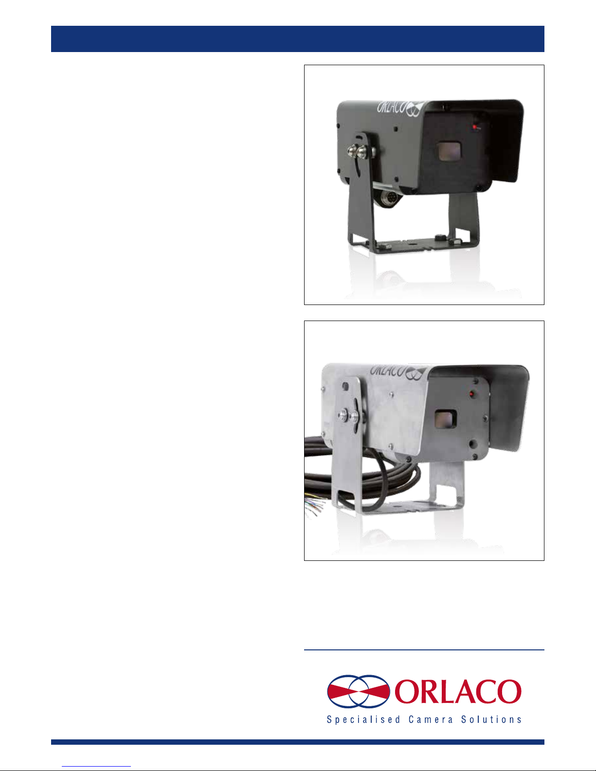
Art. no. 0103732 Camera TIC 320 9hz connector type
Art. no. 0103742 Camera TIC SSt
2 IM0973120 A 01
Installation Manual
Camera TIC Alu/SSt
Art. no. 0103742; Camera TIC SSt
Art. no. 0103732; Camera TIC 320 9hz connector type
Safety
In order to guarantee safe operation, these safety instructions must be read before you start using this equipment.
• Do not open the enclosure. The camera is pressurised. This can cause
damage, short-circuiting or electrical shocks.
• Do not expose the equipment to extreme temperatures. This can cause
deformation of the enclosure or damage to internal components.
• Repairs or adjustments to the equipment may only be undertaken by
Orlaco.
• The equipment must be assembled as shown in this manual.
• If there have been alterations or changes to this equipment that have
not been specifically approved by Orlaco, use of this equipment is not
permitted.
Before you start using this equipment, please read this manual carefully
and follow all instructions. This installation manual describes the functions of the equipment, outlines the connection options and explains how
to put the equipment into operation. We recommend that you keep this
manual in a safe place for reference purposes.
If you have any questions or issues concerning the operation of this
equipment, consult the relevant section in the manual or contact the
Orlaco Products BV Service department.
The camera and monitor systems from Orlaco comply with the latest CE,
ADR, EMC and mirror-directive regulations. All products are manufactured in accordance with the ISO 9001 quality management, ISO/TS16949
quality automotive and ISO 14001 environmental management.
Contents Page
1. Introduction 3
2. Mounting 3
3. Operation 3
3.1. Overpressure in the enclosure 3
3.2. Valve 3
3.3. Switching on and off 3
4. Electrical installation 4
4.1. Camera 4
4.2. Supplied cable 4
5. Instructions for use 5
6. Trouble shooting 5
7. Technical specifications 6
8. Dimensions 6
9. Pelco-D commands 7
10. Maintenance and cleaning 9
11. Disposal 9
12. General terms and conditions 9
11. Release notes 9
Available documentation
DS0103742 Camera TIC SSt
DS0103732 Camera TIC 320 9hz connector type
Art. no. 0103732 Camera TIC 320 9hz connector type
With Art. no. 0304410 Cable 6,0m m7M m7F
Art. no. 0103742 Camera TIC SSt
0113740 Camera TIC SSt
IM0973120 A 01 3
122,0
141,5
260,0
109,0
140,2
141,5
Installation Manual
1. Introduction
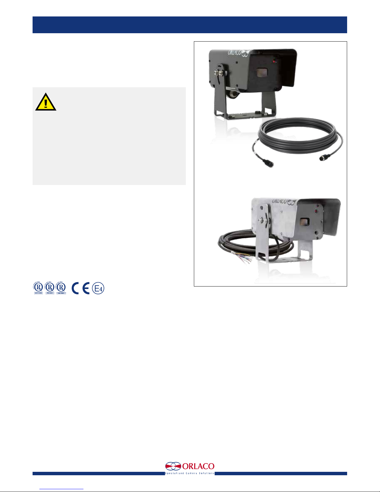
The Thermal Image Camera TIC gives in all weather, day or night, in fog
or smoke a clear picture of the situation.
The Camera TIC can be operated with the Orlaco Monitor 7" RLED/LEDD
and the Orlaco Monitor 12" RLED.
2. Mounting
A camera bracket is supplied with the Camera TIC Alu/Sst; the package
includes the necessary nuts, bolts and washers.
Use of a different type of bracket or bracket made by a different
manufacturer is not permitted.
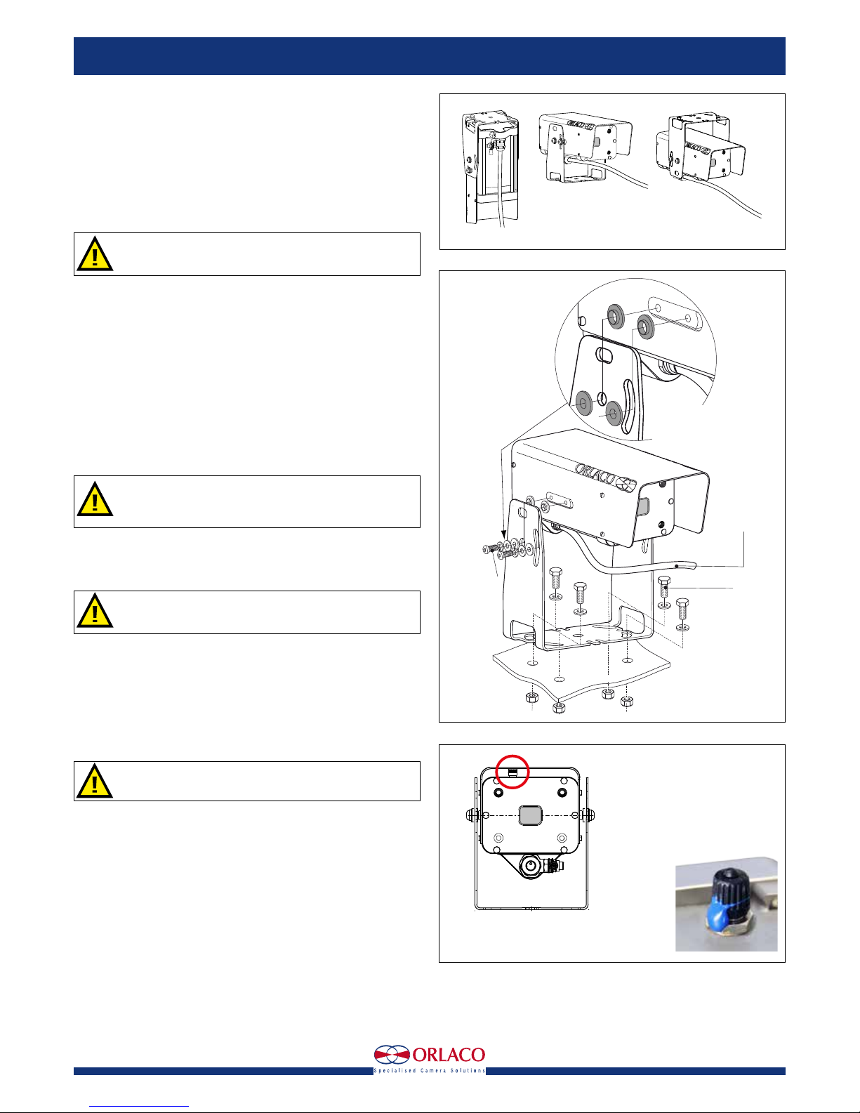
This bracket is suitable for mounting the camera in hanging, standing and
overhead positions, see figure 1. Use a Allen key to adjust the bracket to
the camera with M6 socket head cap screws. Use a 13-mm open-ended
spanner to secure the camera bracket with four M8 bolts, nuts and washers. See figure 2.
3. Operation
3.1. Overpressure in the enclosure
The enclosure of the Camera TIC is with dry-nitrogen filled and has a 1,4
Bar overpressure, therefore IP68 according to IEC 60529 (25 m under
water).
3.2. Valve
WARNING: Do not open the enclosure.
The enclosure is protected by static pressurisation (Nitrogen).
The enclosure shall be filled only by the manufacturer.
The filling valve, may ONLY be used by the manufacturer. Do not remove
the blue seal. See figure 3 A. The warranty expires when the blue seal
is broken!
The warranty expires when the user does not act according the
instructions.
If the pressure is lost send the device back to the manufacturer for investigation, repair and testing.
3.3. Switching on and off
The Camera TIC Alu/SSt is switched on by connecting the connector
cables to the power supply. It is switched off by disconnecting the Power
cable from the power supply. Under normal circumstances, the system
starts once the power is 24V/DC+/-10%.
Ensure that all parts are firmly fixed, stable and secure.
Figure 2
Figure 3
Figure 1
Filling valve
with blue seal
A
A
Bracket overhead
Bracket standing
Bracket hanging
Camera TIC Sst; Art. no. 0103740
M8
M6
1221300
5m cable
Attention:
Always use the
Isolation manchets
Camera TIC Sst
Art. no. 0103740
4 IM0973120 A 01
4. Electrical installation
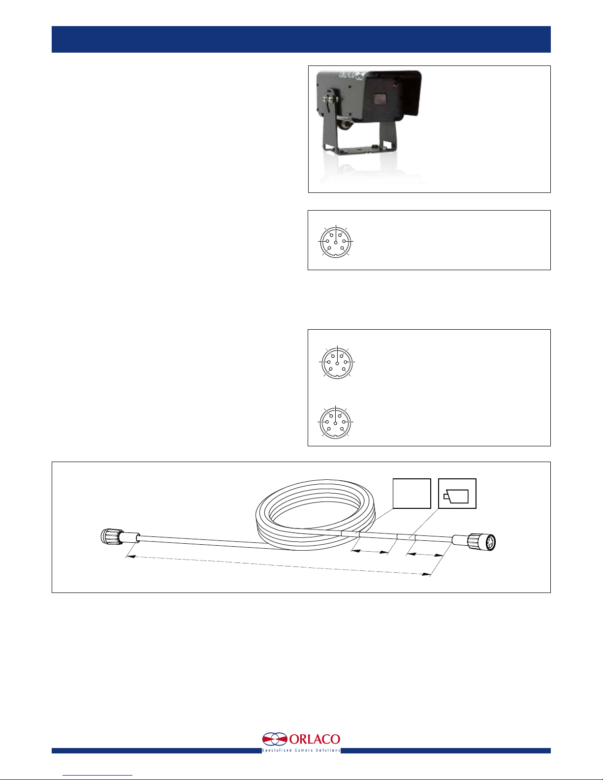
4.1. Camera TIC 9hz connector type
Art. no. 0103732
Electrical connections, see figure 4
Solder side of 7p male socket.
1 = Coax core Video
2 = Coax shielding Video GND
3 = Red Camera power, 12...30V/DC
4 = Black Camera 0V
5 = Yellow Serial 1 TX
6 = Orange Serial 2 RX
7 = Grey N.C.
Shielding GND
4.2. Supplied cable
Art. no. 0304410 Cable 6,0m m7M m7F, see figure 6.
Electrical connections, see figure 5
Front side of 7p molded connector.
1 = Coax Core Video
2 = Coax Shield Video GND
3 = Red Power input
4 = Black 0V
5 = Orange Rx
6 = Yellow Tx
7 = Grey N.C.
For specifications; see Data sheet DS0304410
2
5
7
4
3
6
1
Solder side
7p male socket
Figure 4
2
5
7
4
3
6
1
2
5
7
4
3
6
1
Front side molded
7P Male connector
Front side molded
7P Female connector
Cable length
100
100
0304***
YM
Label 1
Label 2
CAMERA-END
Molded connector 7pin male
Molded connector
7pin female
Figure 5
Figure 6
Art. no. 0103732 Camera TIC 320 9hz connector type
Installation Manual
 Loading...