

Page 1

Camera AFZ PAL Serial
Camera AFZ NTSC Serial
Camera AFZ Sst
Camera AFZ PAL HW
Installation Manual
Manual No. IM0973112, A 03
Article no. 0103481, 0113481
0103512
0103531, 0113531
0103561, 0113561
01/2016
English
Page 2
2 IM0973112 A 03 IM0973112 A 03 3
Installation Manual
Camera AFZ Sst; Art. no. 0103481
Camera AFZ Sst RS485; Art. no. 0113481
Camera AFZ PAL HW; Art. no. 0103512
Camera AFZ PAL Serial; Art. no. 0103531
Camera AFZ PAL Serial RS485; Art. no. 0113531
Camera AFZ NTSC Serial; Art. no. 0103561
Camera AFZ NTSC Serial RS485; Art. no. 0113561
Safety
In order to guarantee safe operation, these safety instructions must be read before you start using this equipment.
• Do not open the enclosure. The camera is pressurised. This can cause
damage, short-circuiting or electrical shocks.
• Do not expose the equipment to extreme temperatures. This can cause
deformation of the enclosure or damage to internal components.
• Repairs or adjustments to the equipment may only be undertaken by
Orlaco.
• The equipment must be assembled as shown in this manual.
• If there have been alterations or changes to this equipment that have
not been specifically approved by Orlaco, use of this equipment is not
permitted.
Before you start using this equipment, please read this manual carefully
and follow all instructions. This installation manual describes the functions of the equipment, outlines the connection options and explains how
to put the equipment into operation. We recommend that you keep this
manual in a safe place for reference purposes.
If you have any questions or issues concerning the operation of this
equipment, consult the relevant section in the manual or contact the
Orlaco Products BV Service department.
The camera and monitor systems from Orlaco comply with the latest CE,
ADR, EMC and mirror-directive regulations. All products are manufactured in accordance with the ISO 9001 quality management, ISO/TS16949
quality automotive and ISO 14001 environmental management.
Contents Page
1. Introduction 3
2. Mounting 3
3. Operation 3
3.1. Overpressure in the enclosure 3
3.2. Valve 3
3.3. Switching on and off 3
4. Electrical installation 4
4.1. Camera 4
4.2. Supplied cable 4
4.3. Camera 5
5 Technical specifications 6
6. Dimensions 7
7. Pelco-D commands 8
8. Jittter 10
9. Maintenance and cleaning 10
10. Disposal 10
11. General terms and conditions 11
12. Release notes 11
Installation Manual
Available documentation
DS0103481 Camera AFZ Sst (0113481)
DS0961301-0103512 Camera AFZ PAL HW
DS0103531 Camera AFZ PAL Serial (0113531)
DS0103561 Camera AFZ NTSC Serial (0113561)
Art. no.
0103531/0113531/0103561/0113561
Art. no. 0103481/0113481
Art. no. 0103512
1. Introduction
These Auto Focus Zoom (AFZ) cameras have excellent specification
properties for maximum performance on the different workstations, such
as cranes, emergency vehicles, vessels and military vehicles.
2. Mounting
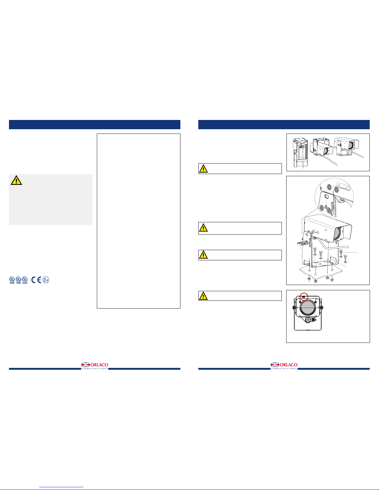
A camera bracket is supplied with the Camera AFZ Alu/Sst; the package
includes the necessary nuts, bolts and washers.
Use of a different type of bracket or bracket made by a different
manufacturer is not permitted.
This bracket is suitable for mounting the camera in hanging, standing and
overhead positions, see figure 1. Use a Allen key to adjust the bracket to
the camera with M6 socket head cap screws. Use a 13-mm open-ended
spanner to secure the camera bracket with four M8 bolts, nuts and washers. See figure 2.
3. Operation
3.1. Overpressure in the enclosure
The enclosure of the Camera AFZ is with dry-nitrogen filled and has a 1,4
Bar overpressure, therefore IP68 according to IEC 60529 (25 m under
water).
3.2. Valve
WARNING: Do not open the enclosure.
The enclosure is protected by static pressurisation (Nitrogen).
The enclosure shall be filled only by the manu-facturer.
The filling valve, may ONLY be used by the manufacturer. Do not remove
the blue seal. See figure 3 A. The warranty expires when the blue seal
is broken!
The warranty expires when the user does not act according the
instructions.
If the pressure is lost send the device back to the manufacturer for investigation, repair and testing.
3.3. Switching on and off
The Camera AFZ Alu/SSt is switched on by connecting the connector
cables to the power supply. It is switched off by disconnecting the Power
cable from the power supply. Under normal circumstances, the system
starts once the power is 24V/DC+/-10%.
Ensure that all parts are firmly fixed, stable and secure.
Figure 2
Figure 3
M8
M6
Attention:
Always use the
Isolation manchets
Figure 1
Filling valve
with blue seal
Indicatie light
(red)
Camera ON
122,0
141,5
109,0
140,2
260,0
141,5
A
A
Bracket overhead
Bracket standing
Bracket hanging
Page 3
4 IM0973112 A 03 IM0973112 A 03 5
4. Electrical installation
4.1. Cameras:
Art. no. 0103531 Camera AFZ PAL Serial
Art. no. 0113531 Camera AFZ PAL Serial RS485
Art. no. 0103561 Camera AFZ NTSC Serial
Art. no. 0113561 Camera AFZ NTSC Serial RS485
Art. no. 0103481 Camera AFZ Sst
Art. no. 0113481 Camera AFZ Sst RS485
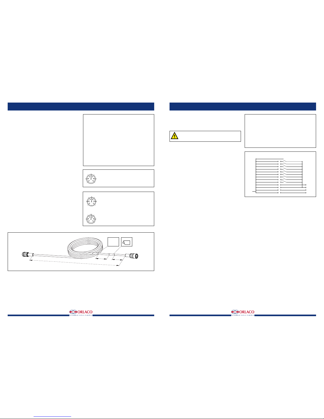
Camera connector 7p male, see figure 4.
Electrical connections:
1 = Coax core (Video signal)
2 = Coax shielding (Video GND)
3 = Red (12...24V/DC)
4 = Black (0V)
5 = Orange (Serial TX)
6 = Yellow (Serial RX)
7 = Grey (Not connected)
Shielding GND
4.2. Supplied cable
Art. no 0304410 Cable 6,0m m7M m7F, see figure 6.
Electrical connections, see figure 5.
1 = Coax Core
2 = Coax Shield
3 = Red (Power input)
4 = Black (0V)
5 = Orange (Rx)
6 = Yellow (Tx)
7 = Grey (Aux)
For specifications; see Data sheet DS0304410
4.3. Camera
Art. no. 0103512 Camera AFZ PAL Hard wired.
Cable Art. no 1220250. Length 10m.
Cable connections, see figure 7.
The Camera AFZ Alu/Sst must be connected by qualified
electricians. Under no circumstances you should make
connections that are not described in this manual.
2
5
7
4
3
6
1
Solder side
7p male connector
Figure 4
2
5
7
4
3
6
1
2
5
7
4
3
6
1
Front side molded
7P Male connector
Front side molded
7P Female connector
Cable length
100
100
0304***
YM
Label 1
Label 2
CAMERA-END
Molded connector 7pin male
Molded connector
7pin female
Figure 5
Figure 6
Art. no. 0103531, 0103561
Art. no. 0103481
1220250
5 m Multi cable
14 White/black; not connected
13 Green Brightness on/off
12 Purple Autofocus on/off
11 White 0-Lux on/off
10 Red/Black Zoom in slow
9 Blue Zoom out slow
8 Grey Zoom in fast
7 Brown Zoom out fast
6 Yellow Focus
5 Pink Focus
4 Black 0V
3 Red Power input
2 Coax shielding Video GND
1 Coax core Video signal
+
12-24V/DC
Figure 7
Art. no. 0103511
Installation Manual Installation Manual
Page 4
6 IM0973112 A 03 IM0973112 A 03 7
UNITS IN MM
Indicatie light
(red)
Camera ON
Indicatie light
(green)
Heating ON
(Demister 2 heater)
122,0
96,0
13,0
80,0
74,9
7,7
40,0
14,7
R4,5 +0,5 -0,0
∅10,0
122,0
141,5
109,0
140,2
260,0
122,0
141,5
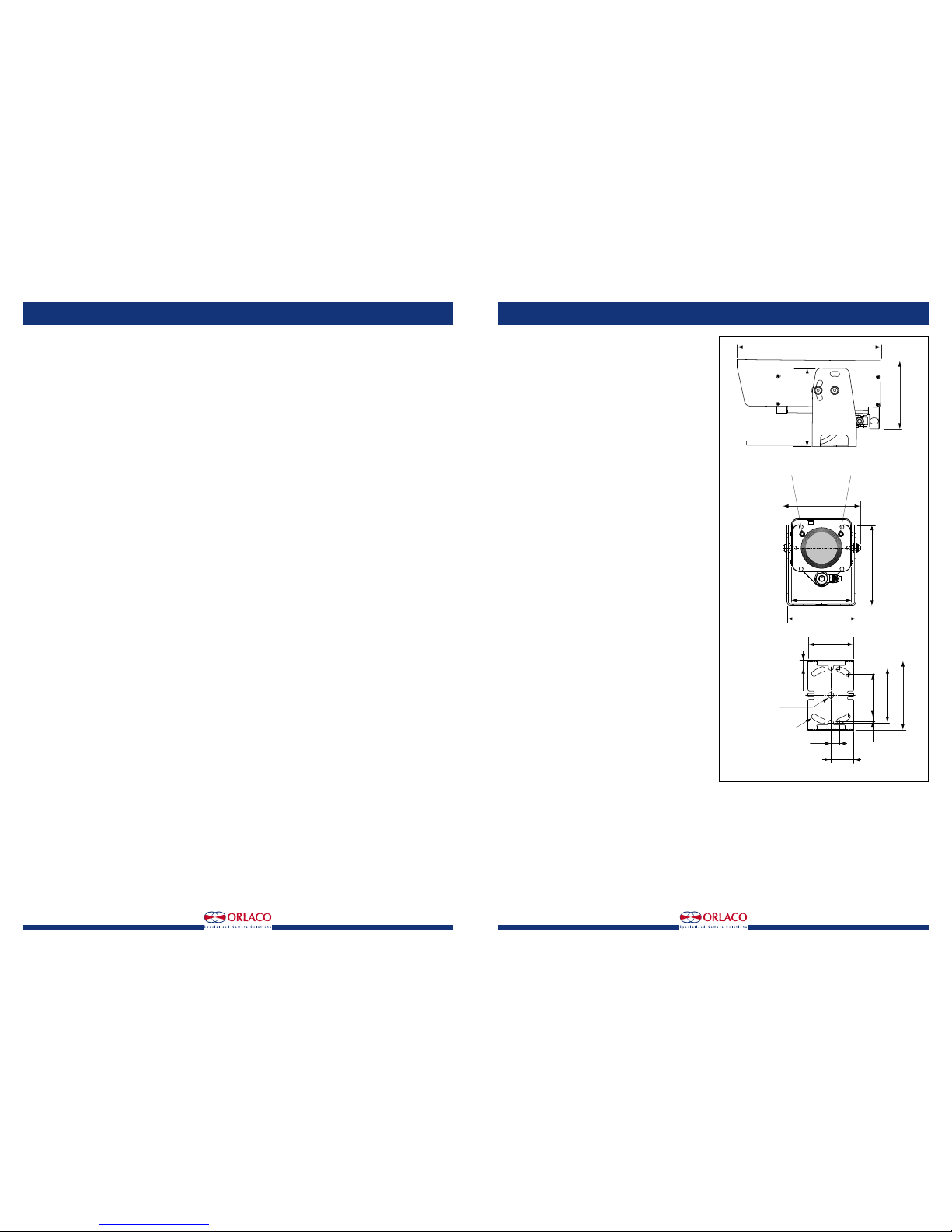
6. Dimensions
Installation Manual Installation Manual
5. Technical specications
5.1. Cameras:
Art. no. 0103531 Camera AFZ PAL Serial
Art. no. 0113531 Camera AFZ PAL Serial RS485
Art. no. 0103561 Camera AFZ NTSC Serial
Art. no. 0113561 Camera AFZ NTSC Serial RS485
Art. no. 0103481 Camera AFZ Sst
Art. no. 0113481 Camera AFZ Sst RS485
CCD sensor: 1/4” type Super HAD CCD II.
Effective pixels: ± 570000 pixels (PAL).
Hor. resolution: 670 TV lines.
Lens: 40x optical zoom f = 3.06 mm to 122.4 mm (WIDE), F1.6 to F4.6
(TELE), 12x digital.
Lens speed: From wide optical to tele optical 3,5 sec.
Angle of view (H): 60° (wide) 1,6° (tele).
Min. working distance: 10 mm (WIDE end), 1500 mm (TELE end).
Min. illumination: 0,6lux (1/60sec), 0,04lux (1/3sec). 0 lux mode.
S/N ratio: 50 dB or more.
TV system: PAL, CVBS, Output: 1 Vtt composite video into 75 ohm.
Presets: 128 presets Visca and 255 presets Pelco-D.
Construction Alu: Stainless steel QS304, mounting parts and sun cover,
anodised Aluminium housing, suitable for mobile applications with
shocks and vibrations. Corrosion proof housing according to IEC 600682-52 salt mist, cyclic.
Construction Sst: Housing, mounting parts and sun cover; stainless
steel QS304, suitable for mobile applications with shocks and vibrations.
Corrosion proof housing according to IEC 60068-2-52 salt mist, cyclic.
Ingress protection: IP 68 according to IEC 60529 (25 m under water),
dry-nitrogen filled, 1,4 Bar overpressure.
Bracket Alu: Standard Alu bracket, including bolts, nuts and washers.
Suitable for mounting overhead and standing.
Bracket Sst: Stainless steel bracket, including bolts, nuts and washers.
Suitable for mounting overhead and standing.
Operating temperature: -40°C to +85°C.
Glass: Chemically hardened lens glass, 7x stronger than ordinary glass,
scratchproof surface, following “VII Flachgläser”(German std.).
Weight Alu: 2,6 kg.
Weight Sst: 5,1 kg.
Power input: Cable between camera and power supply < 50 m 12-24V/
DC, > 50 m 18-24V/DC.
Power consumption: Temperature <0°C (heating on): 7,2 W & >0°C
(heating off): 3,6 W.
Communication: Communication via serial interface, Visca-, Pelco-D
protocol (RS232 or RS485) 9,6 Kbps. (For Art.no 0103511; through pin
nr. 5 and 6 on the 7 poles connector).
Green Passport: All materials are compliant to Green Passport
requirements according IMO resolution MEPC.197(62) as adopted on
15 July 2011 (Maritime sector: International Maritime Organization
concerning the functions of the Marine Environment Protection
Committee).
5.2. Cameras:
Art. no. 0103512 Camera AFZ PAL Hard wired.
CCD sensor: 1/4” type Super HAD CCD II.
Effective pixels: ± 570000 pixels (PAL).
Hor. resolution: 670 TV lines.
Lens: 40x optical zoom f = 3.06 mm to 122.4 mm (WIDE), F1.6 to F4.6
(TELE), 12x digital.
Lens speed: From wide optical to tele optical 3,5 sec.
Angle of view (H): 60° (wide) 1,6° (tele).
Min. working distance: 10 mm (WIDE end), 1500 mm (TELE end).
Min. illumination: 0,6lux (1/60sec), 0,04lux (1/3sec). 0 lux mode.
S/N ratio: 50 dB or more.
TV system: PAL, CVBS, Output: 1 Vtt composite video into 75 ohm.
Presets: 128 presets Visca and 255 presets Pelco-D.
Construction Alu: Stainless steel QS304, mounting parts and sun cover,
anodised Aluminium housing, suitable for mobile applications with
shocks and vibrations. Corrosion proof housing according to IEC 600682-52 salt mist, cyclic.
Ingress protection: IP 68 according to IEC 60529 (25 m under water),
dry-nitrogen filled, 1,4 Bar overpressure.
Bracket Alu: Standard Alu bracket, including bolts, nuts and washers.
Suitable for mounting overhead and standing.
Operating temperature: -40°C to +85°C.
Glass: Chemically hardened lens glass, 7x stronger than ordinary glass,
scratchproof surface, following “VII Flachgläser”(German std.).
Weight Alu: 2,6 kg.
Power input: Cable between camera and power supply < 50 m 12-24V/
DC, > 50 m 18-24V/DC.
Power consumption: Temperature <0°C (heating on): 7,2 W & >0°C
(heating off): 3,6 W.
Communication: Hard wired input
Green Passport: All materials are compliant to Green Passport
requirements according IMO resolution MEPC.197(62) as adopted on
15 July 2011 (Maritime sector: International Maritime Organization
concerning the functions of the Marine Environment Protection
Committee).
Page 5
8 IM0973112 A 03 IM0973112 A 03 9
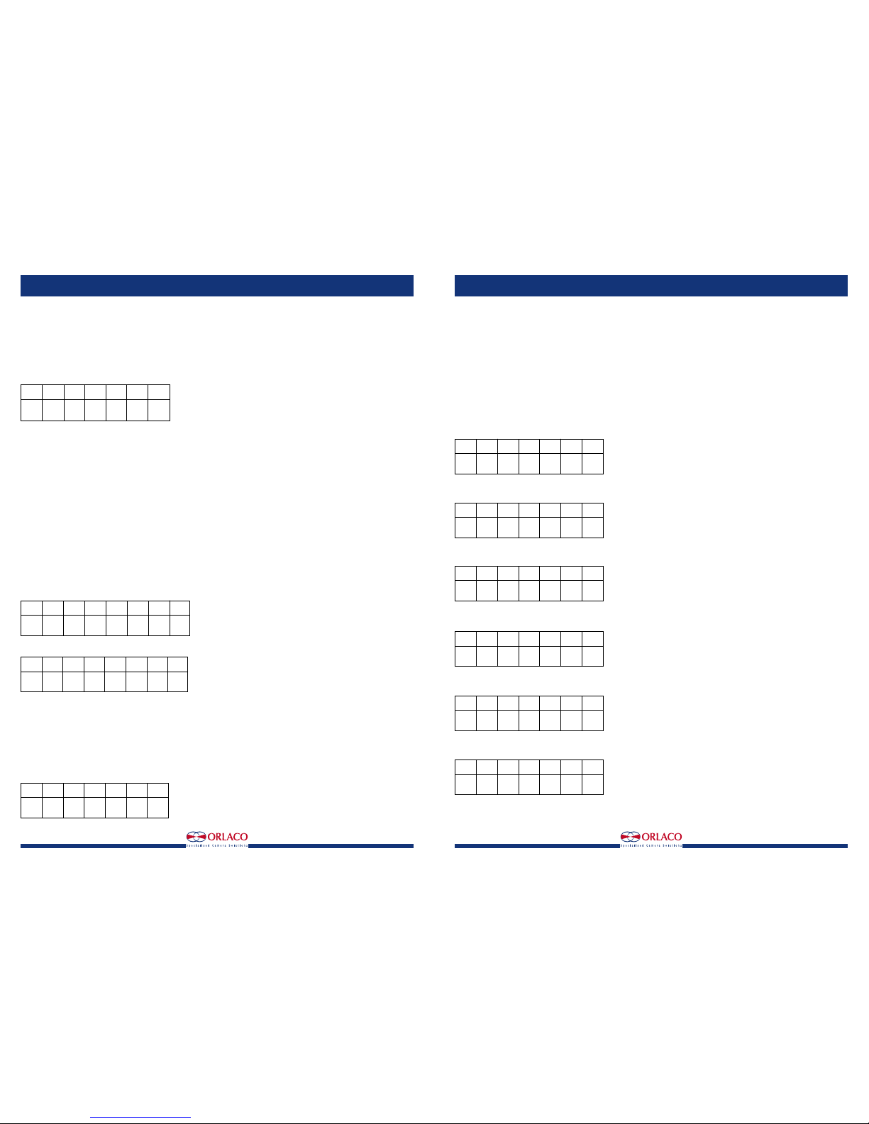
Set preset is also used for some special function by using a special Preset ID.
Pan/Tilt unit:
Preset ID 0x56 Start wipe/wash cycle, this blocks white hot LUT selection in pan/tilt/TIC combination.
Autofocus camera:
Preset ID 0x58 and 0x15 will switch the IR block filter into the optical path.
Preset ID 0x59 and 0x16 will switch the IR block filter out of the optical path.
TIC camera:
Preset ID 0x55 Switch to the Black hot color LUT.
Preset ID 0x56 Switch to the White hot color LUT (not available when combined with pan/tilt unit).
Preset ID 0x57 Switch to the Ice&fire color LUT.
Preset ID 0x58 and 0x15 Switch to the Rainbow color LUT.
Preset ID 0x59 and 0x16 Will force a flat field calibration cycle.
Clear Preset:
Byte Byte 2 Byte 3 Byte 4 Byte 5 Byte 6 Byte 7
Sync addr. 0x00 0x05 0x00 Preset chksm
0xff ID
Preset ID valid range = 0-5.
Go To Preset (not for TIC camera):
Byte 1 Byte 2 Byte 3 Byte 4 Byte 5 Byte 6 Byte 7
Sync addr. 0x00 0x07 0x00 Preset chksm
0xff ID
Preset ID valid range = 0-5.
Set Zoom Speed:
Byte 1 Byte 2 Byte 3 Byte 4 Byte 5 Byte 6 Byte 7
Sync addr. 0x00 0x25 0x00 Zoom chksm
0xff Speed
Remarks: Zoom speed valid values 0-3.
Set Focus Speed:
Byte 1 Byte 2 Byte 3 Byte 4 Byte 5 Byte 6 Byte 7
Sync addr. 0x00 0x27 0x00 Focus chksm
0xff Speed
Remarks: Focus speed valid values 0-3.
Auto-focus auto/on/off:
Byte 1 Byte 2 Byte 3 Byte 4 Byte 5 Byte 6 Byte 7
Sync addr. 0x00 0x2B 0x00 Focus chksm
0xff ctrl
Remarks: Focus ctrl 0,1 = Auto, 2 = off.
Backlight compensation on/off:
Byte 1 Byte 2 Byte 3 Byte 4 Byte 5 Byte 6 Byte 7
Sync addr. 0x00 0x31 0x00 BLC chksm
0xff ctrl
Remarks: BLC ctrl 1 = off, 2 = on.
Installation Manual Installation Manual
7. Pelco-D commands
Pelco-D protocol as implemented in Orlaco Zoom camera or PTZ unit.
Commands detailed below are accepted, no responses are sent.
Bron:Pelco PTZ protocols, D Protocol, Version 5.0.1 1 april 2008 by Eric Hamilton (C) Pelco.
Command format:
All commands are seven (D Protocol)bytes long.
D Protocol Command Format/Names:
Byte 1 Byte 2 Byte 3 Byte 4 Byte 5 Byte 6 Byte 7
Sync addr. cmnd1 cmnd2 data1 data2 chksm
0xff
Bytes D Protocol:
1 sync : Always 0xFF to indicate the start of a command.
2 addr : Camera address. Range is 1 ! 255 (0x01 ! 0xFF). 0x01 is for camera #1, etc.
3 cmnd1 : Extension of the basic command. The basic command is in the cmnd2 position.
4 cmnd2 : The basic command. For extended commands, all of these are odd numbers.
5 data1 : Usually is the Pan speed index.
6 data2 : Usually is the Tilt speed index.
7 cksm : This is the arithmetic sum of all bytes except for the sync byte and itself.
Command Sets
There are two sets/types of commands:
1 “Motion” commands, i.e. pan, tilt, iris, zoom and focus; are “bit encoded” commands that always have bit 0 in cmnd2 set to 0.
Any number of non-exclusive bits may be set in the cmnd1 and cmnd2 bytes for this format of command, data1 and data2 are pan and tilt speed index.
2 “Non-motion” commands, i.e. call preset, set pan angular position; are “numerically encoded”.
These commands always have bit 0 in cmnd2 set to a 1.
Implemented “Motion” commands:
cmnd1 and cmnd2 are represented as follows:
Byte 3, cmnd1
Bit 7 Bit 6 Bit 4 Bit 4 Bit 3 Bit 2 Bit 1 Bit 0
0 0 0 0 0 0 0 Focus
Near
Byte 4, cmnd2
Bit 7 Bit 6 Bit 5 Bit 4 Bit 3 Bit 2 Bit 1 Bit 0
Focus Zoom Zoom Down Up Left Right 0
Far Wide Tele
Data1, Data2 (Pan/Tilt speed), Byte 5,6 contain the speed.
Speed is in the range of `0x00’ to `0x3F’ (high speed) and `0x40’ for “turbo” speed.
Turbo speed is the maximum speed the device can obtain.
A pan speed value of `0x00’ results in very slow motion, not cessation of motion.
To stop pan motion both the Left and Right direction bits must be turned off, set to `0’,
regardless of the value set in the pan speed byte.
Implemented “Non-motion” commands.
Set Preset (TIC has only special presets):
Byte 1 Byte 2 Byte 3 Byte 4 Byte 5 Byte 6 Byte 7
Sync addr. 0x00 0x03 0x00 Preset chksm
0xff ID
Preset ID valid range = 0-5.
Page 6
10 IM0973112 A 03 IM0973112 A 03 11
Installation Manual Installation Manual
8. Jitter (e.g. wobbling image during zoom).
Some viewing equipment are more sensitive to horizontal jitter (e.g. wobbling image during zoom). When this horizontal jitter occurs, below visca
commands can be send sequentially to lower the jitter.
1 8x 01 7F 01 7F FF
2 8x 01 7F 7F 02 00 00 01 08 00 FF
3 8x 01 7F 7F 02 0F 02 05 00 01 FF
4 Cycle power off/on of the camera
To reset camera to Factory default setting (PLL), send following commands:
1 8x 01 7F 01 7F FF
2 8x 01 7F 7F 02 00 00 01 08 00 FF
3 8x 01 7F 7F 02 0F 02 05 00 00 FF
4 Cycle power off/on of the camera
Only use this commands in combination with a PAL
Camera.
Only send this commands once as it is stored in the
EEPROM.
9. Maintenance and cleaning
Use a soft cloth to remove dirt etc. from the lens.
Do not clean this product with aggressive
chemicals or abrasive cleaning agents.
10. Disposal
Disassembly, removal and disposal. Local regulations for dealing with
waste must be followed when disposing of disassembled components or
entire units.
11. General terms and conditions
Orlaco Products BV is not liable for damage resulting from inadequate
servicing, incorrect usage or alterations made to the equipment without
informing the manufacturer in writing.
This installation manual has been made available by Orlaco Products
BV. All rights reserved. No part of this manual may be reproduced and/
or made public in printed form, in photocopy form or on microfilm, or in
any other way, without the prior written permission of Orlaco. This also
applies to the associated drawings and figures.
Orlaco reserves the right to make changes to components at any time
without informing customers beforehand or directly. All dimensions given
are for commercial purposes.
For information regarding repairs that is not covered in this manual,
please contact the Orlaco Products BV service department.
This manual has been prepared with all due care and attention. However,
Orlaco Products BV cannot be held responsible for any errors in this
manual or any consequences thereof.
FCC compliance statement:
The camera comes under section for commodity codes for electronic
equipment. This is known as “Harmonize code: 8525.30.9060” and the
importer can check off Block 2 on FCC form which states: “An FCC grant
of equipment authorization and an FCC ID are not required, but the equipment complies with FCC technical requirements.”
Caution: Any changes or modifications in the construction of this device
which are not expressly approved by the party responsible for compliance
could void the user’s authority to operate the equipment. Camera/Display
sets are visual aids and objects visible in camera/Display systems are
smaller or bigger than they appear on screen.
12. Release Notes
R1-0. New edition, Januari 2016.
A 01. Cable length added at Camera AFZ HW, October 2016.
A 02. Specs: 0 lux mode added, November 2016.
A 03. Specs Hard wired camera changed, December 2016.
Page 7

Orlaco is a Manufacturing company that specializes in making cameras
and monitor systems for commercial vehicles, fork-lift trucks, cranes, off
shore and maritime.
Our objective is to design and produce camera systems for the professional market that improve the drivers view and increase operating
efficiency.
At our factory in Barneveld, we have a production department, warehouse, design department, service department and showroom.
Vision is our mission®, and Orlaco therefore deploys the development,
manufacture, supply and service of camera and display systems that will
improve safety and efficiency of all vehicles, machinery and vessels. Our
systems give the end user a view on each blind spot and create comfort
and improved working conditions. Our active approach will support market demands and innovations and will lead to enthusiastic ambassadors
in the market; our Customers.
For more information: www.orlaco.com
ORLACO
 Loading...