

Page 1
HF-3004-8
© Copyright ORIENTAL MOTOR CO.,LTD. 2000
Thank you for purchasing ORIENTAL MOTOR products.
Please read this operating manual thoroughly before
installing and operating the fan, and always keep the
manual where it is readily accessible.
AC Axial Flow Fans MRS Series
MRW18 Type
OPERATING MANUAL
1. Precautions
1.1 Precautions for Installation
●Do not use in a place where there is flammable gas and/or corrosive gas.
●Fans for use only in equipment of protection class Ⅰ.
Lüfter zur Verwendung in Geräten der Schutzklasse Ⅰ.
●Connect the ground wire to the ground terminal inside the terminal box.
Das Erdungskabel wird an dem als Erde gekennzeichneten Pol im Anschluβkasten angeklemmt.
●When installing the fan into your equipment, ensure that the motor lead wires are fixed and do not move.
In addition, do not apply any pressure to these lead wires.
●Installation must be performed by a qualified installer.
1.2 Precautions for Operation
●Always turn off power to thermally protected fan before conducting checks or performing work on the fan.
These types of fans will restart automatically when fan temperature falls below a certain level.
●The enclosure temperature of this fan can exceed 70 (depending on operation conditions).
In case fan is accessible during operation, please attach the following warning label so that it is clearly visible. Warning label
●Do not touch the fan blades when the fan is in operation.
The use of the optional fingerguard is recommended to ensure protection.
Wegen der Verletzungsgefahr dürfen die Lüfterflügel bei Ventilatorbetrieb nicht berührt werden.
Der Gebrauch des als Sonderzubehör erhältlichen Fingerschutzes ist empfehlenswert, um erhöhte Sicherheit zu gewährleisten.
〈Table of Contents〉
1. Precautions・・・・・・・・・・・・・・・・・・・・・・・・Page 1 4. Installation ・・・・・・・・・・・・・・・・・・・・・・・ Page 3
2. Checking the package contents
・・・・・・・Page 1 5. Alarm Function ・・・・・・・・・・・・・・・・・・・ Page 4
3. Connection
・・・・・・・・・・・・・・・・・・・・・・・・・Page 2 6. Overheat Protection ・・・・・・・・・・・・・・・Page 4
2. Checking the package contents
2.1 Checking the contents
Please make sure that the package contains all of the items listed below.
Contact your nearest ORIENTAL MOTOR office if any of these items are not included or are defective.
・Fan・・・・・・・・・・・・・・・・・・・・・・・・・・・・・・ 1 piece
・Capacitor・・・・・・・・・・・・・・・・・・・・・・・・・1 piece
・Capacitor cap・・・・・・・・・・・・・・・・・・・・・ 1 piece
(Capacitor and Capacitor cap come only with MRS20 single-phase models and MRS18/MRS16 and MRW18 single-phase models with alarm circuits.)
・Operating manual (this manual)・・・・・ 1 piece
2.2 Checking the model name
This manual covers the products specified below.
Please make sure that the model, voltage, current as you ordered by the nameplate.
[Standard type]
MRS20-BUL, MRS20-DUL, MRS20-E, MRS20-TUL, MRS18-BUL, MRS18-DUL, MRS18-E, MRS18-TUL,
MRS16-BUL, MRS16-DUL, MRS16-E, MRS16-TUL, MRS14-TUL
[with electronic type Alarm circuit]
MRS20-BM, MRS20-DM, MRS20-EM, MRS20-TM, MRS18-BTM, MRS18-DTM, MRS18-ETM, MRS18-TTM,
MRS16-BTM, MRS16-DTM, MRS16-ETM, MRS16-TTM, MRS14-TTM
[with contact type Alarm circuit]
MRS16-BTA, MRS16-DTA, MRS16-TTA, MRW18-BTA*, MRW18-DTA*, MRW18-TTA*
C
1
Page 2
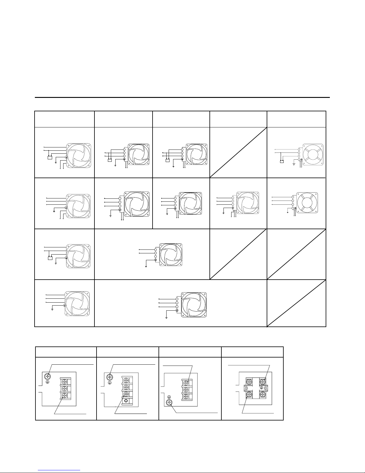
3.Connection
3.1ConnectionDiagrams
MRS20
MRS18,MRS16
MRW18
MRS14
MRS16
single-phase models
with electronic type alarm circuit
Black
Gray
White
Black
Ground
Capacitor
Line
Orange
Alarm lead wires
Black
Gray
White
Black
Ground
Orange
Alarm lead wires
U
V
W
Black
Gray
White
Ground
Capacitor
Line
Black
Gray
White
Ground
U
V
W
1
2
3
Line
Capacitor
Ground
Orange
Black
Alarm lead wires
1
2
3
Line
Capacitor
Ground
White
Black
Alarm lead wires
1
2
3
Ground
Orange
Black
Alarm lead wires
U
V
W
1
2
3
Ground
White
Black
Alarm lead wires
U
V
W
1
2
3
Line
Ground
1
2
3
Ground
U
V
W
1
2
3
Ground
Orange
Black
Red
Alarm lead wires
U
V
W
Alarm lead wires
White
Black
Ground
Capacitor
Line
1
2
3
4
Alarm lead wires
White
Black
Ground
1
2
3
4
U
V
W
MRS18
MRS16
MRW18
3.2Inside the terminal box
MRS14
1
2
3
123
Ground terminal (green)
M4×8
Terminal screws
3-M4×12
1
2
3
1234
Terminal screws
3-M4×12
Ground terminal (green)
M4×8
1
2
3
132
Terminal screws
Ground terminal (green)
M4×8
3-M4×12
Ground terminal (green)
1
2
3
1
2
4
3
4
Terminal screws
4-M4
The recommended tightening torque for the terminal screws is 1.4N・m(198.26oz-in).
single-phase models
with electronic type alarm circuit
single-phase models
with contact type alarm circuit
single-phase models
with contact type alarm circuit
three-phase models
with contact type alarm circuit
three-phase models
with electronic type alarm circuit
three-phase models
with electronic type alarm circuit
three-phase models
with electronic type alarm circuit
three-phase models
with contact type alarm circuit
Fans are recognized by UL and certified by CSA and VDE.
・Standards UL507, CSA C22.2 No.113, EN60950
・Approval Conditions for EN Standards Overvoltage categoryⅡ, Pollution degree 2, Class Ⅰ equipment
*The certificate of the MRW18 types by VDE is valid only for the fan assembly itself. The capacitor is not included in the certificate.
However, both the fan assembly and capacitor combined have been tested against and have passed EN60950 Annex B.8.
The
MRW18 types are recognized by UL under CSA standard (C-UL).
three-phase models standard type
three-phase models standard type
single-phase models standard type
single-phase models standard type
2
Page 3

4.1 Mounting the fan
To mount the fan, drill holes in the machinery in which it will be installed
referring to Panel-Cut-Out ( see General Catalog ) and then fasten the
fan with screw.
The direction of airflow is indicated by the AIRFLOW mark on the side
of the fan frame. The arrow points in the direction of the outlet.
The rotation arrow indicates the direction of rotation. Screws for attaching are not provided.
Please use the proper screws.
4.2 Mounting the capacitor
(MRS20 Single-phase models and MRS18/MRS16 and MRW18 single-phase models with alarm circuits.)
Before mounting the capacitor, check to see that the capacitance of the capacitor provided,
matches the capacitance indicated on the fan's nameplate.
Use M4 screw (not provided) to mount the capacitor.
Note : Tighten the capacitor mounting screw with a torque of 1 N
・m(141.61oz-in)
or less in order to prevent damaging the mounting leg.
4.3 Mounting the capacitor cap
(MRS20 Single-phase models and MRS18/MRS16 and MRW18 single-phase models with alarm circuits.)
Use the capacitor cap provided for insulation of the capacitor terminal connections.
① Pass the lead wires through the capacitor cap as shown in figure.
② Connect the lead wires to the terminals or use terminal ends.
③ Cap the capacitor with the capacitor cap.
4.4 Capacitor Connection (case of 4-terminal type : MRW18 type)
The capacitor internal wiring is as follows:
Capacitor terminals are internally electrically connected in twos;
A-B and C-D for easy connection.
For easy to install terminals use #187 series AMP terminals.
For lead wire connection, use one lead wire for each individual terminal.
φ4.3(.17DIA.)
4. Installation
Install the fan and capacitor in locations that meet following conditions.
・Indoors (the product is designed and manufactured to be mounted in a machine.)
・Ambient temperature −10 (14ºF)〜+60 (140ºF) (Non-freezing)
(
−10 (14ºF)〜+50 (122ºF) for MRW18 type)
・Ambient humidity 0〜85% (Non-condensing)
・No explosive, flammable, and/or corrosive gas.
・No exposure to direct sunlight.
・No splashing of water, or exposure to dust or debris.
・No oil or grease, organic solvents, acid or alkaline chemicals.
・No continuous vibration or excessive shock.
・Overvoltage categoryⅡ, Pollution degree 2, ClassⅠequipment (EN standard).
Model
Screw
Dimensions
Tightening
torque
MRS14 type
Other MRS series
MRW18 type
M4
M5
0.6N・m(84.97oz-in)
1.2N・m(169.93oz-in)
(case of 2-terminal type)
2
1
3
Capacitor cap
Capacitor
(case of 2-terminal type)
A
B
C
D
AMP #187
<Crimp style terminals that can be used> Unit=mm(inch)
●Round terminal type with insulation ●U-shaped terminal type with insulation
V1.25-4 AV1.25YS4A
(JAPAN SOLDERLESS TERMINAL MFG. CO., LTD.) (JAPAN SOLDERLESS TERMINAL MFG. CO., LTD.)
or other equivalent product or other equivalent product
3
Unit=mm(inch)
φ
4.3(.17DIA.)min.
9(.35)min.
9(.35)min.
4.3(.17)min.
8(.31)max.
8(.31)max.
Page 4

5. Alarm Function
■with electronic type alarm circuit
An alarm (high-level) signal is output when the fan's rotation speed falls below 1800±300 r/min.
Maximum voltage : Vout max.
=30V DC
Leakage current : I
=250μA max.
Maximum current : lout max.
=15mA
Output saturated voltage : Vout(sat)
=0.4V max.
■with contact type alarm circuit
Contact to be made when the fan's rotation speed falls below 1800±300 r/min.
Output rating : resistance load 10VA max. (100V max. and 0.5A max. )
Alarm Wiring
with electronic type alarm circuit with contact type alarm circuit
except for the
MRS14-TTM MRS14-TTM
Note :Except for the MRS14-TTM, the alarm circuits do not have a delay function.
Avoiding detection, when starting the fan, for example, requires an external delay function.
Set the delay time to 10 seconds (min.)
6. Overheat Protection
To prevent burning out the windings as a result of overheating, MRS series and MRW18 type fans have been designed with a
protector explained below.
Thermal protector ; Automatic return type
Operating temperature of thermal protectors
Open : 120
± 5 (248ºF±9ºF)
Close : 77
±15
(170ºF
± 27ºF)
Black
White
Alarm output
Black
Red
Orange
Alarm output
GND
5VDC
Black
Orange
Alarm output
GND
4
●Characteristics, specifications and dimensions are subject to change without notice.
●Please contact your nearest ORIENTAL MOTOR office for further information.
TAIWAN ORIENTAL MOTOR CO.,LTD.
Tel:(02)2299-9360 Fax:(02)2299-4173
SINGAPORE ORIENTAL MOTOR PTE LTD.
Tel:(745)7344 Fax:(745)9405
ORIENTAL MOTOR KOREA CO.,LTD.
Tel:(02)632-9122 Fax:(02)679-4588
ORIENTAL MOTOR CO.,LTD.
Headquarters
Tel:(03)3835-0684 Fax:(03)3835-1890
ORIENTAL MOTOR (EUROPA) GmbH
Headquarters and Düsseldorf Office
Tel:02131-95280 Fax:02131-952899
Munich Office
Tel:08131-59880 Fax:08131-598888
Hamburg Office
Tel:04076-910443 Fax:04076-910445
ORIENTAL MOTOR (UK) LTD.
Tel:01252-519809 Fax:01252-547086
ORIENTAL MOTOR (FRANCE) SARL
Tel:01 47 86 97 50 Fax:01 47 82 45 16
ORIENTAL MOTOR ITALIA s.r.l
Tel:02-3390541 Fax:02-33910033
ORIENTAL MOTOR U.S.A. CORP.
Los Angeles Office Tel:(310)784-8200 Fax:(310)325-1076
San Jose Office Tel:(408)358-6900 Fax:(408)358-8200
Chicago Office Tel:(847)240-2649 Fax:(847)240-2753
Cincinnati Office Tel:(513)563-2722 Fax:(513)956-3183
Austin Office Tel:(512)918-9438 Fax:(512)335-5983
New York Office Tel:(973)359-1100 Fax:(973)359-1090
Boston Office Tel:(781)848-2426 Fax:(781)848-2617
Atlanta Office Tel:(770)716-2800 Fax:(770)719-8515
Canada Office Tel:(905)502-5333 Fax:(905)502-5444
Technical Support Line:(800)468-3982
Available from 8:30 AM to 8:00 PM, Eastern Time
 Loading...