

ORIX MRW-18, MRS20-BUL, MRS20-E, MRS20-DUL, MRS20-TUL Operating Manual
...
HF-3004-8
© Copyright ORIENTAL MOTOR CO.,LTD. 2000
Thank you for purchasing ORIENTAL MOTOR products.
Please read this operating manual thoroughly before
installing and operating the fan, and always keep the
manual where it is readily accessible.
AC Axial Flow Fans MRS Series
MRW18 Type
OPERATING MANUAL
1. Precautions
1.1 Precautions for Installation
●Do not use in a place where there is flammable gas and/or corrosive gas.
●Fans for use only in equipment of protection class Ⅰ.
Lüfter zur Verwendung in Geräten der Schutzklasse Ⅰ.
●Connect the ground wire to the ground terminal inside the terminal box.
Das Erdungskabel wird an dem als Erde gekennzeichneten Pol im Anschluβkasten angeklemmt.
●When installing the fan into your equipment, ensure that the motor lead wires are fixed and do not move.
In addition, do not apply any pressure to these lead wires.
●Installation must be performed by a qualified installer.
1.2 Precautions for Operation
●Always turn off power to thermally protected fan before conducting checks or performing work on the fan.
These types of fans will restart automatically when fan temperature falls below a certain level.
●The enclosure temperature of this fan can exceed 70 (depending on operation conditions).
In case fan is accessible during operation, please attach the following warning label so that it is clearly visible. Warning label
●Do not touch the fan blades when the fan is in operation.
The use of the optional fingerguard is recommended to ensure protection.
Wegen der Verletzungsgefahr dürfen die Lüfterflügel bei Ventilatorbetrieb nicht berührt werden.
Der Gebrauch des als Sonderzubehör erhältlichen Fingerschutzes ist empfehlenswert, um erhöhte Sicherheit zu gewährleisten.
〈Table of Contents〉
1. Precautions・・・・・・・・・・・・・・・・・・・・・・・・Page 1 4. Installation ・・・・・・・・・・・・・・・・・・・・・・・ Page 3
2. Checking the package contents
・・・・・・・Page 1 5. Alarm Function ・・・・・・・・・・・・・・・・・・・ Page 4
3. Connection
・・・・・・・・・・・・・・・・・・・・・・・・・Page 2 6. Overheat Protection ・・・・・・・・・・・・・・・Page 4
2. Checking the package contents
2.1 Checking the contents
Please make sure that the package contains all of the items listed below.
Contact your nearest ORIENTAL MOTOR office if any of these items are not included or are defective.
・Fan・・・・・・・・・・・・・・・・・・・・・・・・・・・・・・ 1 piece
・Capacitor・・・・・・・・・・・・・・・・・・・・・・・・・1 piece
・Capacitor cap・・・・・・・・・・・・・・・・・・・・・ 1 piece
(Capacitor and Capacitor cap come only with MRS20 single-phase models and MRS18/MRS16 and MRW18 single-phase models with alarm circuits.)
・Operating manual (this manual)・・・・・ 1 piece
2.2 Checking the model name
This manual covers the products specified below.
Please make sure that the model, voltage, current as you ordered by the nameplate.
[Standard type]
MRS20-BUL, MRS20-DUL, MRS20-E, MRS20-TUL, MRS18-BUL, MRS18-DUL, MRS18-E, MRS18-TUL,
MRS16-BUL, MRS16-DUL, MRS16-E, MRS16-TUL, MRS14-TUL
[with electronic type Alarm circuit]
MRS20-BM, MRS20-DM, MRS20-EM, MRS20-TM, MRS18-BTM, MRS18-DTM, MRS18-ETM, MRS18-TTM,
MRS16-BTM, MRS16-DTM, MRS16-ETM, MRS16-TTM, MRS14-TTM
[with contact type Alarm circuit]
MRS16-BTA, MRS16-DTA, MRS16-TTA, MRW18-BTA*, MRW18-DTA*, MRW18-TTA*
C
1
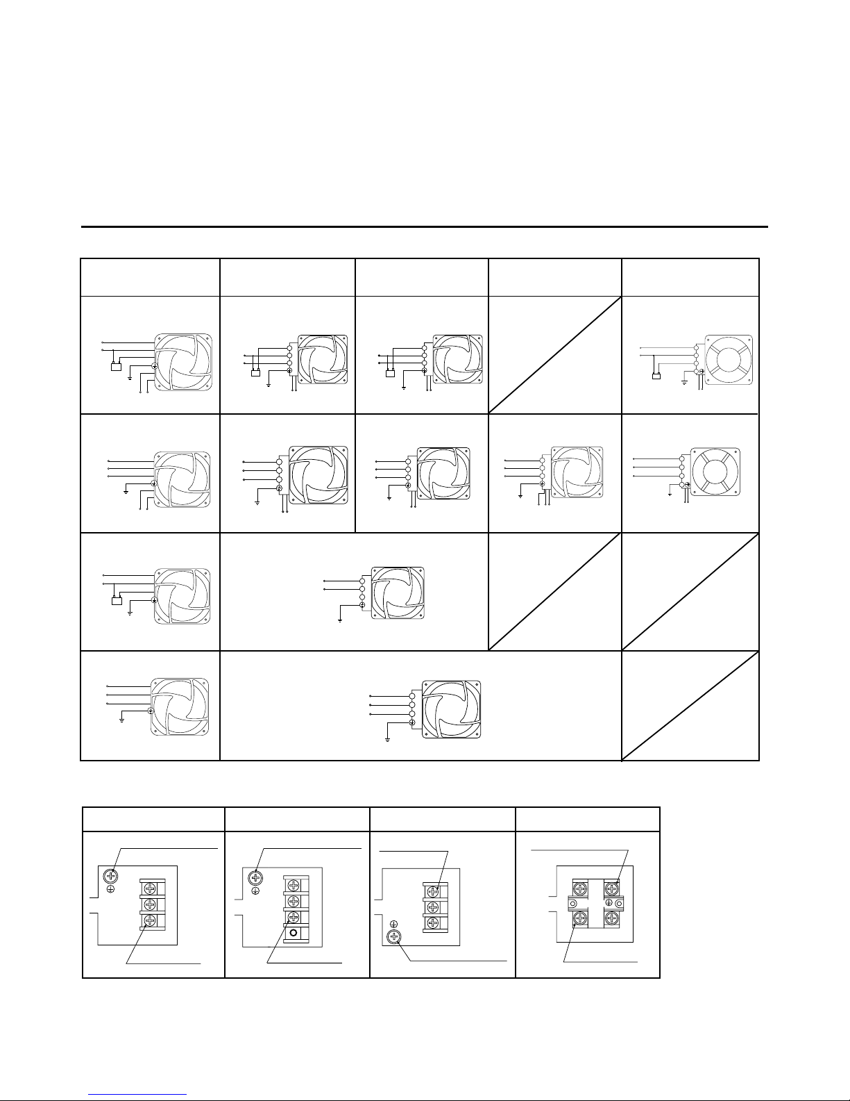
3.Connection
3.1ConnectionDiagrams
MRS20
MRS18,MRS16
MRW18
MRS14
MRS16
single-phase models
with electronic type alarm circuit
Black
Gray
White
Black
Ground
Capacitor
Line
Orange
Alarm lead wires
Black
Gray
White
Black
Ground
Orange
Alarm lead wires
U
V
W
Black
Gray
White
Ground
Capacitor
Line
Black
Gray
White
Ground
U
V
W
1
2
3
Line
Capacitor
Ground
Orange
Black
Alarm lead wires
1
2
3
Line
Capacitor
Ground
White
Black
Alarm lead wires
1
2
3
Ground
Orange
Black
Alarm lead wires
U
V
W
1
2
3
Ground
White
Black
Alarm lead wires
U
V
W
1
2
3
Line
Ground
1
2
3
Ground
U
V
W
1
2
3
Ground
Orange
Black
Red
Alarm lead wires
U
V
W
Alarm lead wires
White
Black
Ground
Capacitor
Line
1
2
3
4
Alarm lead wires
White
Black
Ground
1
2
3
4
U
V
W
MRS18
MRS16
MRW18
3.2Inside the terminal box
MRS14
1
2
3
123
Ground terminal (green)
M4×8
Terminal screws
3-M4×12
1
2
3
1234
Terminal screws
3-M4×12
Ground terminal (green)
M4×8
1
2
3
132
Terminal screws
Ground terminal (green)
M4×8
3-M4×12
Ground terminal (green)
1
2
3
1
2
4
3
4
Terminal screws
4-M4
The recommended tightening torque for the terminal screws is 1.4N・m(198.26oz-in).
single-phase models
with electronic type alarm circuit
single-phase models
with contact type alarm circuit
single-phase models
with contact type alarm circuit
three-phase models
with contact type alarm circuit
three-phase models
with electronic type alarm circuit
three-phase models
with electronic type alarm circuit
three-phase models
with electronic type alarm circuit
three-phase models
with contact type alarm circuit
Fans are recognized by UL and certified by CSA and VDE.
・Standards UL507, CSA C22.2 No.113, EN60950
・Approval Conditions for EN Standards Overvoltage categoryⅡ, Pollution degree 2, Class Ⅰ equipment
*The certificate of the MRW18 types by VDE is valid only for the fan assembly itself. The capacitor is not included in the certificate.
However, both the fan assembly and capacitor combined have been tested against and have passed EN60950 Annex B.8.
The
MRW18 types are recognized by UL under CSA standard (C-UL).
three-phase models standard type
three-phase models standard type
single-phase models standard type
single-phase models standard type
2
 Loading...