

Page 1

ICS-2100 Ion Chromatography System
Operator’s Manual
Document No. 065291
Revision 01
March 2009
Page 2

©2009 by Dionex Corporation
All rights reserved worldwide.
Printed in the United States of America.
This publication is protected by federal copyright law. No part of this publication
may be copied or distributed, transmitte d, tr anscribed, stored in a retrieval system, or
transmitted into any human or computer language, in any form or by any means,
electronic, mechanical, magnetic, manual, or otherwise, or disclosed to third parties
without the express written permission of Dione x Corporation , 1228 Titan Way,
Sunnyvale, California 94088-3603 U.S.A.
DISCLAIMER OF WARRANTY AND LIMITED WARRANTY
THIS PUBLICATION IS PROVIDED “AS IS” WITHOUT WARRANTY OF
ANY KIND. DIONEX CORPORATION DOES NOT WARRANT,
GUARANTEE, OR MAKE ANY EXPRESS OR IMPLIED
REPRESENTATIONS REGARDING THE USE, OR THE RESULTS OF T HE
USE, OF THIS PUBLICA TION IN TERMS OF CORRECTNESS, ACCURACY,
RELIABILITY, CURRENTNESS, OR OTHERWISE. FURTHER, DIONEX
CORPORATION RESERVES THE RIGHT TO REVISE THIS PUBLICATION
AND TO MAKE CHANGES FROM TIME TO TIME IN THE CONTENT
HEREINOF WITHOUT OBLIGATION OF DIONEX CORPORATION TO
NOTIFY ANY PERSON OR ORGANIZATION OF SUCH REVISION OR
CHANGES.
TRADEMARKS
AES, AMMS ICE, ASRS, Chromeleon, EluGen, IonPac, OnGuard, and SRS are
registered trademarks of Dionex Corporation. AutoNeutraliz ation, MicroMembran e,
MMS, and MonoDisk are trademarks of Dionex Corporation.
Acrobat, Adobe, and Adobe Reader are registered trademarks of Adobe Systems,
Incorporated.
Microsoft and Windows Vista are registered trademarks of Microsoft Corporation.
PEEK is a trademark of Victrex PLC.
Teflon is a registered trademark of E.I. duPont de Nemours & Company.
PRINTING HISTORY
Revision 01, March 2009
Page 3

Contents
1 • Introduction. . . . . . . . . . . . . . . . . . . . . . . . . . . . . . . . . . . . . . . . . . . . . . 1
1.1 Introduction to Ion Chromatography (IC) . . . . . . . . . . . . . . . . . . . . . . . . 1
1.2 Overview of the ICS-2100 . . . . . . . . . . . . . . . . . . . . . . . . . . . . . . . . . . . . 4
1.3 About This Manual . . . . . . . . . . . . . . . . . . . . . . . . . . . . . . . . . . . . . . . . . 5
1.3.1 Safety Messages and Notes . . . . . . . . . . . . . . . . . . . . . . . . . . . . 6
1.4 Safety and Regulatory Information . . . . . . . . . . . . . . . . . . . . . . . . . . . . . 8
1.4.1 Safety Labels . . . . . . . . . . . . . . . . . . . . . . . . . . . . . . . . . . . . . . . 8
2 • Features. . . . . . . . . . . . . . . . . . . . . . . . . . . . . . . . . . . . . . . . . . . . . . . . . . 11
2.1 Operating Features . . . . . . . . . . . . . . . . . . . . . . . . . . . . . . . . . . . . . . . . . 11
2.1.1 Front Panel . . . . . . . . . . . . . . . . . . . . . . . . . . . . . . . . . . . . . . . . 11
2.1.2 Top Cover . . . . . . . . . . . . . . . . . . . . . . . . . . . . . . . . . . . . . . . . . 16
2.1.3 Component Panel . . . . . . . . . . . . . . . . . . . . . . . . . . . . . . . . . . . 18
2.1.4 Rear Panel . . . . . . . . . . . . . . . . . . . . . . . . . . . . . . . . . . . . . . . . . 21
2.2 Flow Schematics . . . . . . . . . . . . . . . . . . . . . . . . . . . . . . . . . . . . . . . . . . 23
2.3 Chromeleon and Chromeleon Xpress . . . . . . . . . . . . . . . . . . . . . . . . . . 30
2.3.1 The Panel Tabset . . . . . . . . . . . . . . . . . . . . . . . . . . . . . . . . . . . 30
2.3.2 Software Control Modes . . . . . . . . . . . . . . . . . . . . . . . . . . . . . 31
2.3.3 System Wellness . . . . . . . . . . . . . . . . . . . . . . . . . . . . . . . . . . . . 31
2.4 System Component Details . . . . . . . . . . . . . . . . . . . . . . . . . . . . . . . . . . 32
2.4.1 Vacuum Degas Assembly (Optional) . . . . . . . . . . . . . . . . . . . . 32
Doc. 065291-01 3/09 i
Page 4

ICS-2100 Ion Chromatography System
2.4.2 Eluent Valve . . . . . . . . . . . . . . . . . . . . . . . . . . . . . . . . . . . . . . .34
2.4.3 Pump . . . . . . . . . . . . . . . . . . . . . . . . . . . . . . . . . . . . . . . . . . . . .34
2.4.4 Eluent Generator . . . . . . . . . . . . . . . . . . . . . . . . . . . . . . . . . . . .37
2.4.5 Auxiliary Power Supply (Optional) . . . . . . . . . . . . . . . . . . . . . .42
2.4.6 Injection Valve . . . . . . . . . . . . . . . . . . . . . . . . . . . . . . . . . . . . .42
2.4.7 Auxiliary Valve (Optional) . . . . . . . . . . . . . . . . . . . . . . . . . . . .44
2.4.8 Column Heater . . . . . . . . . . . . . . . . . . . . . . . . . . . . . . . . . . . . . .45
2.4.9 Suppressor . . . . . . . . . . . . . . . . . . . . . . . . . . . . . . . . . . . . . . . . .46
2.4.10 DS6 Heated Conductivity Cell . . . . . . . . . . . . . . . . . . . . . . . . . 46
3 • Operation and Maintenance . . . . . . . . . . . . . . . . . . . . . . . .49
3.1 Operation Overview . . . . . . . . . . . . . . . . . . . . . . . . . . . . . . . . . . . . . . . . 49
3.2 Turning On the System Power . . . . . . . . . . . . . . . . . . . . . . . . . . . . . . . .51
3.3 Connecting to Chromeleon . . . . . . . . . . . . . . . . . . . . . . . . . . . . . . . . . . .52
3.4 Set Up the Eluent Reservoir . . . . . . . . . . . . . . . . . . . . . . . . . . . . . . . . . .54
3.4.1 Filter the Deionized Water . . . . . . . . . . . . . . . . . . . . . . . . . . . .54
3.4.2 Fill the Reservoir . . . . . . . . . . . . . . . . . . . . . . . . . . . . . . . . . . . .54
3.4.3 Set the Eluent Level . . . . . . . . . . . . . . . . . . . . . . . . . . . . . . . . . .54
3.4.4 Connect the Reservoir . . . . . . . . . . . . . . . . . . . . . . . . . . . . . . . .56
3.5 Check All Connections . . . . . . . . . . . . . . . . . . . . . . . . . . . . . . . . . . . . . .57
3.6 Prime the Pump . . . . . . . . . . . . . . . . . . . . . . . . . . . . . . . . . . . . . . . . . . .57
3.7 Set System Operating Conditions . . . . . . . . . . . . . . . . . . . . . . . . . . . . . .58
3.8 Equilibrate the System and Verify Operational Status . . . . . . . . . . . . .59
ii Doc. 065291-01 3/09
Page 5

Contents
3.9 Prepare Samples . . . . . . . . . . . . . . . . . . . . . . . . . . . . . . . . . . . . . . . . . . 60
3.9.1 Collecting and Storing Samples . . . . . . . . . . . . . . . . . . . . . . . . 60
3.9.2 Pretreating Samples . . . . . . . . . . . . . . . . . . . . . . . . . . . . . . . . . 61
3.9.3 Diluting Samples . . . . . . . . . . . . . . . . . . . . . . . . . . . . . . . . . . . 61
3.10 Loading and Injecting Samples . . . . . . . . . . . . . . . . . . . . . . . . . . . . . . . 62
3.10.1 Loading Samples with a Syringe . . . . . . . . . . . . . . . . . . . . . . . 63
3.10.2 Loading Samples with a Vacuum Syringe . . . . . . . . . . . . . . . . 64
3.10.3 Loading Samples with an Autosampler . . . . . . . . . . . . . . . . . . 64
3.10.4 Injecting Samples . . . . . . . . . . . . . . . . . . . . . . . . . . . . . . . . . . . 65
3.11 Processing Samples . . . . . . . . . . . . . . . . . . . . . . . . . . . . . . . . . . . . . . . . 65
3.11.1 Manual Sample Processing . . . . . . . . . . . . . . . . . . . . . . . . . . . 65
3.11.2 Automatic (Batch) Sample Processing . . . . . . . . . . . . . . . . . . . 66
3.12 Maintenance . . . . . . . . . . . . . . . . . . . . . . . . . . . . . . . . . . . . . . . . . . . . . 68
4 • Troubleshooting. . . . . . . . . . . . . . . . . . . . . . . . . . . . . . . . . . . . . . . 71
4.1 Error Messages . . . . . . . . . . . . . . . . . . . . . . . . . . . . . . . . . . . . . . . . . . . 71
4.2 Troubleshooting Error Messages . . . . . . . . . . . . . . . . . . . . . . . . . . . . . . 74
4.3 Liquid Leaks . . . . . . . . . . . . . . . . . . . . . . . . . . . . . . . . . . . . . . . . . . . . . 86
4.4 Pump Difficult to Prime or Loses Prime . . . . . . . . . . . . . . . . . . . . . . . . 88
4.5 Pump Does Not Start . . . . . . . . . . . . . . . . . . . . . . . . . . . . . . . . . . . . . . . 90
4.6 No Flow . . . . . . . . . . . . . . . . . . . . . . . . . . . . . . . . . . . . . . . . . . . . . . . . . 90
4.7 Erratic Flow/Pressure Reading . . . . . . . . . . . . . . . . . . . . . . . . . . . . . . . 91
4.8 Excessive System Backpressure . . . . . . . . . . . . . . . . . . . . . . . . . . . . . . 92
4.9 Peak “Ghosting” . . . . . . . . . . . . . . . . . . . . . . . . . . . . . . . . . . . . . . . . . . 93
Doc. 065291-01 3/09 iii
Page 6

ICS-2100 Ion Chromatography System
4.10 Nonreproducible Peak Height or Retention Time . . . . . . . . . . . . . . . . .94
4.11 Abnormal Retention Time or Selectivity . . . . . . . . . . . . . . . . . . . . . . . .94
4.12 No Cell Response . . . . . . . . . . . . . . . . . . . . . . . . . . . . . . . . . . . . . . . . . .94
4.13 High Cell Output . . . . . . . . . . . . . . . . . . . . . . . . . . . . . . . . . . . . . . . . . .95
4.14 Baseline Noise or Drift . . . . . . . . . . . . . . . . . . . . . . . . . . . . . . . . . . . . . .96
4.15 Vacuum Degas Assembly Does Not Run . . . . . . . . . . . . . . . . . . . . . . . .97
5•Service . . . . . . . . . . . . . . . . . . . . . . . . . . . . . . . . . . . . . . . . . . . . . . . . . . . .99
5.1 Diagnostic and Calibration Procedures . . . . . . . . . . . . . . . . . . . . . . . . .99
5.1.1 Chromeleon Wellness Panel Overview . . . . . . . . . . . . . . . . . .100
5.1.2 Diagnostic and Calibration Touch Screen Overview . . . . . . .102
5.1.3 Calibrating the Conductivity Cell . . . . . . . . . . . . . . . . . . . . . .103
5.1.4 Calibrating the Flow Rate . . . . . . . . . . . . . . . . . . . . . . . . . . . .106
5.1.5 Calibrating the Vacuum Degas Assembly . . . . . . . . . . . . . . . .108
5.2 Isolating a Restriction in the Liquid Lines . . . . . . . . . . . . . . . . . . . . . .109
5.3 Replacing Tubing and Fittings . . . . . . . . . . . . . . . . . . . . . . . . . . . . . . .113
5.4 Rebuilding the Injection Valve or Auxiliary Valve . . . . . . . . . . . . . . .114
5.5 Replacing an Auxiliary Valve Pod . . . . . . . . . . . . . . . . . . . . . . . . . . . .116
5.6 Cleaning and Replacing the Pump Check Valves . . . . . . . . . . . . . . . .118
5.7 Replacing a Pump Piston Seal and Piston Rinse Seal . . . . . . . . . . . . .120
5.8 Replacing a Pump Piston . . . . . . . . . . . . . . . . . . . . . . . . . . . . . . . . . . .124
5.9 Replacing the Waste Valve or Priming Valve O-Ring . . . . . . . . . . . . .125
5.10 Replacing the Conductivity Cell . . . . . . . . . . . . . . . . . . . . . . . . . . . . . .127
5.11 Replacing the Suppressor . . . . . . . . . . . . . . . . . . . . . . . . . . . . . . . . . . .130
iv Doc. 065291-01 3/09
Page 7

Contents
5.12 Replacing the Column Heater . . . . . . . . . . . . . . . . . . . . . . . . . . . . . . . 131
5.13 Replacing the Column Heater Heat Exchanger . . . . . . . . . . . . . . . . . . 134
5.14 Replacing the Eluent Valve . . . . . . . . . . . . . . . . . . . . . . . . . . . . . . . . . 135
5.15 Replacing the Leak Sensor . . . . . . . . . . . . . . . . . . . . . . . . . . . . . . . . . 137
5.16 Priming the Pump . . . . . . . . . . . . . . . . . . . . . . . . . . . . . . . . . . . . . . . . 138
5.16.1 Priming the Eluent Lines with a Syringe . . . . . . . . . . . . . . . . 138
5.16.2 Priming with the Prime Button . . . . . . . . . . . . . . . . . . . . . . . . 140
5.17 Priming the Pump with Isopropyl Alcohol . . . . . . . . . . . . . . . . . . . . . 141
5.18 Changing Main Power Fuses . . . . . . . . . . . . . . . . . . . . . . . . . . . . . . . . 142
5.19 Replacing an EluGen Cartridge . . . . . . . . . . . . . . . . . . . . . . . . . . . . . . 143
5.19.1 Replacing a KOH, LiOH, MSA, or NaOH
EluGen Cartridge . . . . . . . . . . . . . . . . . . . . . . . . . . . . . . . . . . . . . . . 143
5.19.2 Replacing a K2CO3 Cartridge . . . . . . . . . . . . . . . . . . . . . . . . 151
5.20 Replacing the CR-TC . . . . . . . . . . . . . . . . . . . . . . . . . . . . . . . . . . . . . 165
5.21 Replacing the EPM Electrolytic pH Modifier . . . . . . . . . . . . . . . . . . . 169
5.21.1 Recording the EPM Serial Number in Chromeleon . . . . . . . . 170
5.21.2 Plumbing the EPM for Hydrating and Conditioning . . . . . . . 171
5.21.3 Hydrating and Conditioning the EPM . . . . . . . . . . . . . . . . . . 173
5.22 Replacing the EGC CO3 Mixer . . . . . . . . . . . . . . . . . . . . . . . . . . . . . . 174
5.22.1 Installing the New EGC CO3 Mixer . . . . . . . . . . . . . . . . . . . 174
5.22.2 Filling the EGC CO3 Mixer with Deionized Water . . . . . . . . 175
5.22.3 Filling the EGC CO3 Mixer with Eluent . . . . . . . . . . . . . . . . 178
5.23 Replacing the EGC Holder and Degas Assembly . . . . . . . . . . . . . . . . 185
5.23.1 Disconnecting and Removing the EluGen Cartridge . . . . . . . 185
Doc. 065291-01 3/09 v
Page 8

ICS-2100 Ion Chromatography System
5.23.2 Removing the CR-TC and Reinstalling it
in the New EGC Holder . . . . . . . . . . . . . . . . . . . . . . . . . . . . .188
5.23.3 Removing the EPM and Reinstalling it
in the New EGC Holder . . . . . . . . . . . . . . . . . . . . . . . . . . . . .190
5.23.4 Installing the New EGC Holder Without a CR-TC
or EPM . . . . . . . . . . . . . . . . . . . . . . . . . . . . . . . . . . . . . . . . . . .192
5.23.5 Reinstalling the EluGen Cartridge . . . . . . . . . . . . . . . . . . . . . .193
A • Specifications . . . . . . . . . . . . . . . . . . . . . . . . . . . . . . . . . . . . . . . . .195
A.1 Electrical . . . . . . . . . . . . . . . . . . . . . . . . . . . . . . . . . . . . . . . . . . . . . . . .195
A.2 Physical . . . . . . . . . . . . . . . . . . . . . . . . . . . . . . . . . . . . . . . . . . . . . . . . .195
A.3 Environmental . . . . . . . . . . . . . . . . . . . . . . . . . . . . . . . . . . . . . . . . . . .196
A.4 Front Panel . . . . . . . . . . . . . . . . . . . . . . . . . . . . . . . . . . . . . . . . . . . . . .196
A.5 Analytical Pump and Fluidics . . . . . . . . . . . . . . . . . . . . . . . . . . . . . . . .196
A.6 Eluent Generation . . . . . . . . . . . . . . . . . . . . . . . . . . . . . . . . . . . . . . . . .198
A.7 Detector Electronics . . . . . . . . . . . . . . . . . . . . . . . . . . . . . . . . . . . . . . .200
A.8 Conductivity Cell with Heat Exchanger . . . . . . . . . . . . . . . . . . . . . . . .200
A.9 Injection Valve . . . . . . . . . . . . . . . . . . . . . . . . . . . . . . . . . . . . . . . . . . .202
A.10 Auxiliary Valve (Optional) . . . . . . . . . . . . . . . . . . . . . . . . . . . . . . . . . .202
A.11 Vacuum Degas Assembly . . . . . . . . . . . . . . . . . . . . . . . . . . . . . . . . . . .202
A.12 Column Heater . . . . . . . . . . . . . . . . . . . . . . . . . . . . . . . . . . . . . . . . . . .202
A.13 Auxiliary Power Supply (Optional) . . . . . . . . . . . . . . . . . . . . . . . . . . .202
A.14 Suppressors . . . . . . . . . . . . . . . . . . . . . . . . . . . . . . . . . . . . . . . . . . . . . .203
A.15 Autosampler . . . . . . . . . . . . . . . . . . . . . . . . . . . . . . . . . . . . . . . . . . . . .204
A.16 System Software . . . . . . . . . . . . . . . . . . . . . . . . . . . . . . . . . . . . . . . . . .204
vi Doc. 065291-01 3/09
Page 9

Contents
B • Touch Screen Operation. . . . . . . . . . . . . . . . . . . . . . . . . . . 207
B.1 Using the Touch Screen . . . . . . . . . . . . . . . . . . . . . . . . . . . . . . . . . . . . 207
B.2 Using the Touch Screen with Chromeleon . . . . . . . . . . . . . . . . . . . . . 210
B.3 Overview of ICS-2100 Touch Screen Pages . . . . . . . . . . . . . . . . . . . . 211
B.4 Home Page . . . . . . . . . . . . . . . . . . . . . . . . . . . . . . . . . . . . . . . . . . . . . . 212
B.4.1 Home Page Pump Controls . . . . . . . . . . . . . . . . . . . . . . . . . . 212
B.4.2 Home Page EGC Controls . . . . . . . . . . . . . . . . . . . . . . . . . . . 214
B.4.3 Home Page Column Heater . . . . . . . . . . . . . . . . . . . . . . . . . . 214
B.4.4 Home Page Injection Valve Controls . . . . . . . . . . . . . . . . . . . 215
B.4.5 Home Page Detector Controls . . . . . . . . . . . . . . . . . . . . . . . . 215
B.4.6 Other Home Page Controls . . . . . . . . . . . . . . . . . . . . . . . . . . . 216
B.5 Plot Page . . . . . . . . . . . . . . . . . . . . . . . . . . . . . . . . . . . . . . . . . . . . . . . 217
B.6 Status Page . . . . . . . . . . . . . . . . . . . . . . . . . . . . . . . . . . . . . . . . . . . . . . 218
B.6.1 Viewing Other Status Parameters . . . . . . . . . . . . . . . . . . . . . . 220
B.6.2 Status Parameter Details . . . . . . . . . . . . . . . . . . . . . . . . . . . . . 221
B.7 Pump Page . . . . . . . . . . . . . . . . . . . . . . . . . . . . . . . . . . . . . . . . . . . . . . 223
B.7.1 Setting Pump Pressure Limits and Selecting
the Pressure Unit 223
B.7.2 Setting Degas Operating Parameters (Optional) . . . . . . . . . . 224
B.7.3 Controlling the Eluent Valve . . . . . . . . . . . . . . . . . . . . . . . . . 225
B.8 Eluent Generator Page . . . . . . . . . . . . . . . . . . . . . . . . . . . . . . . . . . . . . 226
B.8.1 EGC Serial Number . . . . . . . . . . . . . . . . . . . . . . . . . . . . . . . . 226
B.8.2 Setting the Eluent Concentration . . . . . . . . . . . . . . . . . . . . . . 227
B.8.3 Controlling the Eluent Generator Power . . . . . . . . . . . . . . . . 228
Doc. 065291-01 3/09 vii
Page 10

ICS-2100 Ion Chromatography System
B.8.4 Monitoring the EluGen Cartridge Life . . . . . . . . . . . . . . . . . .228
B.8.5 Controlling the CR-TC Power . . . . . . . . . . . . . . . . . . . . . . . . .229
B.9 Suppressor Page . . . . . . . . . . . . . . . . . . . . . . . . . . . . . . . . . . . . . . . . . .230
B.10 Detector Page . . . . . . . . . . . . . . . . . . . . . . . . . . . . . . . . . . . . . . . . . . . .231
B.10.1 Setting the Data Rise Time . . . . . . . . . . . . . . . . . . . . . . . . . . .232
B.10.2 Selecting the Conductivity Polarity . . . . . . . . . . . . . . . . . . . . .232
B.10.3 Setting Analog Out Options . . . . . . . . . . . . . . . . . . . . . . . . . .233
B.11 Information Page . . . . . . . . . . . . . . . . . . . . . . . . . . . . . . . . . . . . . . . . .234
B.12 Module Setup Page . . . . . . . . . . . . . . . . . . . . . . . . . . . . . . . . . . . . . . . .235
B.13 Input/Output Page . . . . . . . . . . . . . . . . . . . . . . . . . . . . . . . . . . . . . . . . .236
B.14 Diagnostic and Calibration Pages . . . . . . . . . . . . . . . . . . . . . . . . . . . . .236
C • TTL and Relay Control. . . . . . . . . . . . . . . . . . . . . . . . . . . . . .239
C.1 TTL and Relay Connections . . . . . . . . . . . . . . . . . . . . . . . . . . . . . . . . .239
C.1.1 Selecting TTL Input Functions and Control Types . . . . . . . . .242
C.2 Controlling TTL and Relay Outputs . . . . . . . . . . . . . . . . . . . . . . . . . . .245
C.3 Example Setup for Stand-Alone Operation . . . . . . . . . . . . . . . . . . . . .246
D • Reordering Information. . . . . . . . . . . . . . . . . . . . . . . . . . . . .251
E•FAQ. . . . . . . . . . . . . . . . . . . . . . . . . . . . . . . . . . . . . . . . . . . . . . . . . . . . . . .255
E.1 How do I hook up an autosampler? . . . . . . . . . . . . . . . . . . . . . . . . . . .255
E.2 How do I print? . . . . . . . . . . . . . . . . . . . . . . . . . . . . . . . . . . . . . . . . . . .255
E.3 Why are the retention times moving? . . . . . . . . . . . . . . . . . . . . . . . . . .255
viii Doc. 065291-01 3/09
Page 11

Contents
E.4 How do I adjust retention times? . . . . . . . . . . . . . . . . . . . . . . . . . . . . . 255
E.5 When should I remake standards? . . . . . . . . . . . . . . . . . . . . . . . . . . . . 255
E.6 When should I replace the eluent generator cartridge? . . . . . . . . . . . 256
E.7 How do I start Chromeleon? . . . . . . . . . . . . . . . . . . . . . . . . . . . . . . . . 256
E.8 How do I delete data? . . . . . . . . . . . . . . . . . . . . . . . . . . . . . . . . . . . . . 256
E.9 How do I back up data? . . . . . . . . . . . . . . . . . . . . . . . . . . . . . . . . . . . . 256
E.10 How do I shut off the system? . . . . . . . . . . . . . . . . . . . . . . . . . . . . . . . 256
E.11 How do I store columns? . . . . . . . . . . . . . . . . . . . . . . . . . . . . . . . . . . . 256
E.12 How do I know when a column is dirty? . . . . . . . . . . . . . . . . . . . . . . . 257
E.13 How do I clean a column? . . . . . . . . . . . . . . . . . . . . . . . . . . . . . . . . . . 257
E.14 Why is the conductivity high? . . . . . . . . . . . . . . . . . . . . . . . . . . . . . . . 257
E.15 How do I configure and operate the auxiliary valve? . . . . . . . . . . . . . 257
F • Glossary . . . . . . . . . . . . . . . . . . . . . . . . . . . . . . . . . . . . . . . . . . . . . . . . 259
Index
Doc. 065291-01 3/09 ix
Page 12

ICS-2100 Ion Chromatography System
x Doc. 065291-01 3/09
Page 13

1 • Introduction
1.1 Introduction to Ion Chromatography (IC)
The Dionex ICS-2100 Ion Chromatography System (ICS-2100) performs ion
analyses using suppressed or non-suppressed conductivity detection. An ion
chromatography system typically consists of a liquid eluent, a high-pressure
pump, a sample injector, a guard and separator column, a chemical suppressor, a
conductivity cell, and a data collection system.
Before running a sample, the ion chromatography system is calibrated using a
standard solution. By comparing the data obtained from a sample to that obtained
from the known standard, sample ions can be identified and quantitated. The data
collection system, typically a computer running chromatography software,
produces a chromatogram (a plot of the detector output vs. time). The
chromatography software converts each peak in the chromatogram to a sample
concentration and produces a printout of the results.
Doc. 065291-01 3/09 1
Page 14
ICS-2100 Ion Chromatography System
n
6
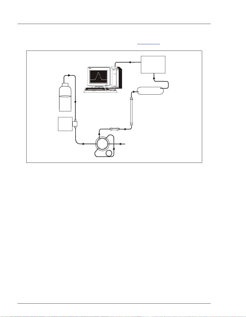
A typical IC analysis consists of six stages (see Figure 1-1).
. Data Analysis
Conductivity
Cell
Suppressor
5. Detectio
1. Eluent
Eluent
Delivery
Pump
2. Sample
Injection
1. Eluent Delivery
• Eluent, a liquid that helps to separate the sample ions, carries the
sample through the ion chromatography system. The ICS-2100
includes an eluent generator, which generates eluent online from
deionized water.
• When the ICS-2100 is controlled from the front panel, only isocratic
eluent delivery is possible. This means that the eluent composition
and concentration remain constant throughout the run. Gradient
delivery (a change in concentration over time) is possible when the
ICS-2100 is controlled by Chromeleon
Management System (the data collection system for the ICS-2100).
4. Suppression
Separator
Column
3. Separation
Guard Column
Injection
Valve
Sample Loop
Sample
Figure 1-1. Ion Analysis Process
®
Chromatography
2. Sample Injection
• The liquid sample is loaded into a sample loop either manually or
automatically (if an automated sampler is installed). When triggered,
the ICS-2100 injects the sample into the eluent stream.
2 Doc. 065291-01 3/09
Page 15

• The pump pushes the eluent and sample through the guard and
separator columns (chemically-inert tubes packed with a polymeric
resin). The guard column removes contaminants that might poison the
separator column.
3. Separation
• As the eluent and sample are pumped through the separator column,
the sample ions are separated. In the ICS-2100, the mode of
separation is called ion exchange. This is based on the premise that
different sample ions migrate through the IC column at different rates,
depending upon their interactions with the ion exchange sites.
4. Suppression
• After the eluent and sample ions leave the column, they flow through
a suppressor that selectively enhances detection of the sample ions
while suppressing the conductivity of the eluent.
5. Detection
• A conductivity cell measures the electrical conductance of the sample
ions as they emerge from the suppressor and produces a signal based
on a chemical or physical property of the analyte.
1 • Introduction
6. Data Analysis
• The conductivity cell transmits the signal to a data collection system.
• The data collection system (for the ICS-2100, this is the
Chromeleon
ions based on retention time, and quantifies each analyte by
integrating the peak area or peak height. The data is quantitated by
comparing the sample peaks in a chromatogram to those produced
from a standard solution. The results are displayed as a chromatogram
and the concentrations of ionic analytes can be automatically
determined and tabulated.
Doc. 065291-01 3/09 3
®
Chromatography Management System) identifies the
Page 16

ICS-2100 Ion Chromatography System
1.2 Overview of the ICS-2100
The ICS-2100 is an integrated ion chromatography system containing an eluent
generator, pump, injection valve, column heater, and conductivity detector. Other
system components, including a guard column, separator column, and suppressor
vary, depending on the analyses to be performed.
The ICS-2100 can be configured with a vacuum degas assembly for online eluent
degassing. If desired, the second eluent generator power supply can be configured
to power an auxiliary electrolytic device, such as a water purifier.
An optional second high-pressure valve (6-port or 10-port) can be installed for
sample preparation applications.
ICS-2100 operation can be controlled in one of two ways:
• Remotely, with a personal computer running Microsoft
Windows XP and Chromeleon software (version 6.80 SR6a or later).
Chromeleon also provides data acquisition and data processing functions.
• Locally, with the front panel LCD touch screen. The touch screen is used for
instrument control only. It does not provide data acquisition or data
processing functions. An analog output on the rear panel can be connected to
a separate data acquisition device.
®
Windows®Vista or
For communication between the ICS-2100 and Chromeleon, the ICS-2100 is
connected to a USB (Universal Serial Bus) port on the computer or a USB hub.
For details, see the ICS-2100 installation instructions. Also refer to Installing the
Chromeleon Chromatography Management System with a Dionex Ion
Chromatograph (IC) (Document No. 031883).
4 Doc. 065291-01 3/09
Page 17

1.3 About This Manual
The electronic version (i.e., PDF file) of this operator’s manual contains numerous
hypertext links that can take you to other locations within the file. These links
include:
• Table of contents entries
• Index entries
• Cross-references (underlined in blue) to sections, figures, tables, etc.
1 • Introduction
If you are not familiar with how to navigate PDF files, refer to the Help system for
Adob
e® Acrobat® or Adobe Reader
Chapter 1
Introduction
Introduces ion analysis and the ICS-2100; explains the
conventions used in this manual, including safety-related
®
for assistance
information.
Chapter 2
Features
Provides an overview of ICS-2100 operating features and
system components; introduces the Chromeleon user
interface.
Chapter 3
Operation and
Maintenance
Chapter 4
Troubleshooting
Chapter 5
Service
Appendix A
Specifications
Appendix B
Touch Screen
Operation
Appendix C
TTL and Relay
Control
Appendix D
Reordering
Information
Provides operating instructions and describes routine
preventive maintenance procedures.
Lists problems, and presents step-by-step procedures for
how to isolate and eliminate the cause of each problem.
Provides step-by-step instructions for routine service and
parts replacement procedures that the user can perform.
Lists the ICS-2100 specifications and installation site
requirements.
Describes the operating features available from the front
panel touch screen.
Describes the ICS-2100 TTL and relay control features.
Lists spare parts for the ICS-2100.
Doc. 065291-01 3/09 5
Page 18
ICS-2100 Ion Chromatography System
Appendix E
FAQ
Appendix F
Provides answers to frequently asked questions about ICS2100 operation.
Defines terms commonly used in ion analysis.
Glossary
1.3.1 Safety Messages and Notes
This manual contains warnings and precautionary statements that, when
properly followed, can prevent personal injury and/or damage to the
instrument. Safety messages appear in bold type and are accompanied by
icons, as shown below.
Indicates an imminently hazardous situation which, if not avoided, will
result in death or serious injury.
Indicates a potentially hazardous situation which, if not avoided,
could result in death or serious injury.
Indicates a potentially hazardous situation which, if not avoided, may
result in minor or moderate injury. Also used to identify a situation or
practice that may seriously damage the instrument, bu t will not c ause
injury.
Indicates that the function or process of the instrument may be
impaired. Operation does not constitute a hazard.
Messages d'avertissement en français
Signale une situation de danger immédiat qui, si elle n'est pas évitée,
entraînera des blessures graves à mortelles.
Signale une situation de danger potentiel qui, si elle n'est pas évitée,
pourrait entraîner des blessures graves à mortelles.
Signale une situation de danger potentiel qui, si elle n'est pas évitée,
pourrait entraîner des blessures mineures à modérées. Également
utilisé pour signaler une situation ou une pratique qui pourrait
gravement endommager l'instrument mais qui n'entraînera pas de
blessures.
6 Doc. 065291-01 3/09
Page 19
1 • Introduction
Warnhinweise in Deutsch
Bedeutet unmittelbare Gefahr. Mißachtung kann zum Tod oder
schwerwiegenden Verletzungen führen.
Bedeutet eine mögliche Gefährdung. Mißachtung kann zum Tod oder
schwerwiegenden Verletzungen führen.
Bedeutet eine mögliche Gefährdung. Mißachtung kann zu kleineren
oder mittelschweren Verletzungen führen. Wird auch verwendet, wenn
eine Situation zu schweren Schäden am Gerät führen kann, jedoch
keine Verletzungsgefahr besteht.
Notes
Informational messages also appear throughout this manual. These are
labeled NOTE and are in bold type:
NOTE NOTES call attention to certain information. They
alert you to an unexpected result of an action,
suggest how to optimize instrument performance,
etc.
Doc. 065291-01 3/09 7
Page 20

ICS-2100 Ion Chromatography System
1.4 Safety and Regulatory Information
The ICS-2100 was manufactured by Dionex Corporation at the following
location: 527 Lakeside Drive, Sunnyvale, CA 94088-3603 U.S.A. The ICS-2100
is designed for IC (ion chromatography) applications and should not be used for
any other purpose. If there is a question regarding appropriate usage, contact
Dionex at 1-800-346-6390 before proceeding. Outside the United States, call the
nearest Dionex office.
1.4.1 Safety Labels
The TUV T-Mark and cTUVus Mark safety labels and the CE Mark label
on the system indicate that it is in compliance with the following
standards:
EMC Susceptibility and Emissions
• EN 61326-1:2006
Safety
• CAN/CSA-C22.2 61010-1:2004
• UL 61010-1:2004
• EN 61010-1:2001
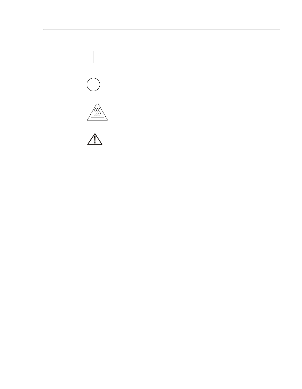
The symbols below appear on the ICS-2100 or on labels affixed to the
ICS-2100.
Alternating current
Primary protective conductor terminal
Secondary protective conductor terminal
8 Doc. 065291-01 3/09
Page 21
1 • Introduction
Power supply is on
Power supply is off
Hot surface
Indicates a potential hazard. Refer to the operator’s manual for
an explanation of the hazard and how to proceed.
Doc. 065291-01 3/09 9
Page 22

ICS-2100 Ion Chromatography System
10 Doc. 065291-01 3/09
Page 23
This chapter describes key ICS-2100 features and introduces the Chromeleon user
interface.
2.1 Operating Features
2.1.1 Front Panel
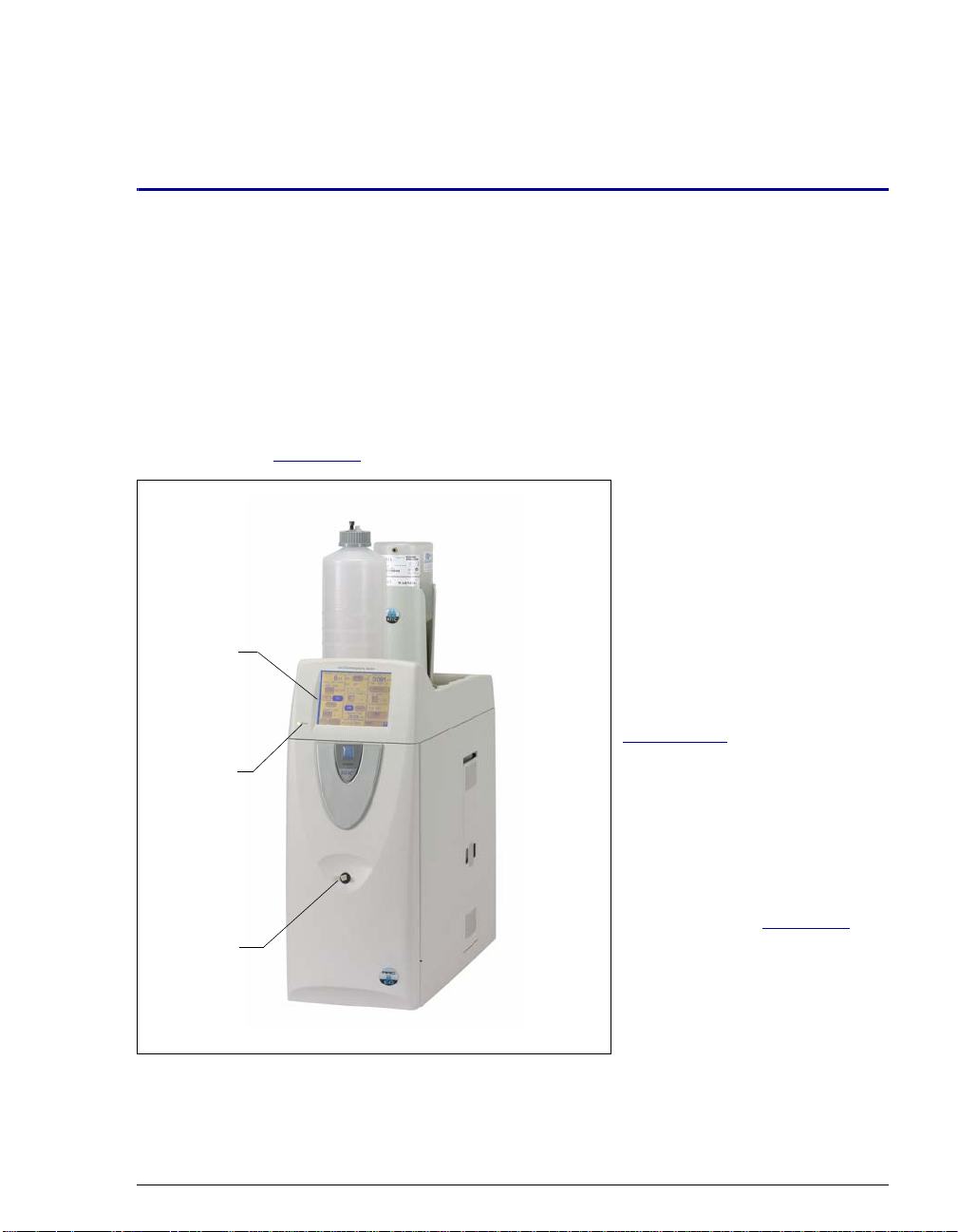
Figure 2-1 illustrates the front panel of the ICS-2100.
Touch
Screen
Power
LED
Injection
Port
2•Features
Injection Port
The sample to be analyzed can
be injected manually into the
injection port, using a syringe.
For automated sample
injection, the ICS-2100 must be
connected to an autosampler.
For more information about
sample injection, see
Section 3.10
Touch Screen
The LCD touch screen provides
local control of most ICS-2100
functions. Yo u can control
many of these functions
directly on the touch screen’s
HOME page (see Figure 2-2).
From the
also go to a series of pages that
provide access to all other
locally controlled ICS-2100
operating functions.
.
HOME page, you can
Figure 2-1. ICS-2100 Front Panel
Doc. 065291-01 3/09 11
Page 24
ICS-2100 Ion Chromatography System
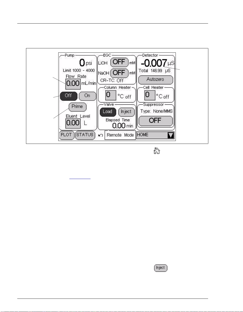
Summary of Touch Screen Operation
Edit Field
Command
Button
(selected)
Command
Button
(unselected)
Figure 2-2. ICS-2100 Touch Screen Home Page
Status Field
NOTE To adjust the screen contrast, open the front door and
adjust the knurled knob under the screen (see
Figure 2-8
).
• Edit fields and command buttons have blue text on a shaded
background. Fields that display status information are not shaded.
• Edit fields have square corners, while command buttons are rounded.
• To select a command button or edit a field, touch and release the
command button or edit field with your fingertip.
NOTE When you touch a button or edit field, the action is
taken when you lift your finger. If you unintentionally
touch a button or field, you can cancel the action by
sliding your finger away from the button or field before
lifting.
• Touching a command button (for example, ) executes the
command immediately.
12 Doc. 065291-01 3/09
Page 25
2 • Features
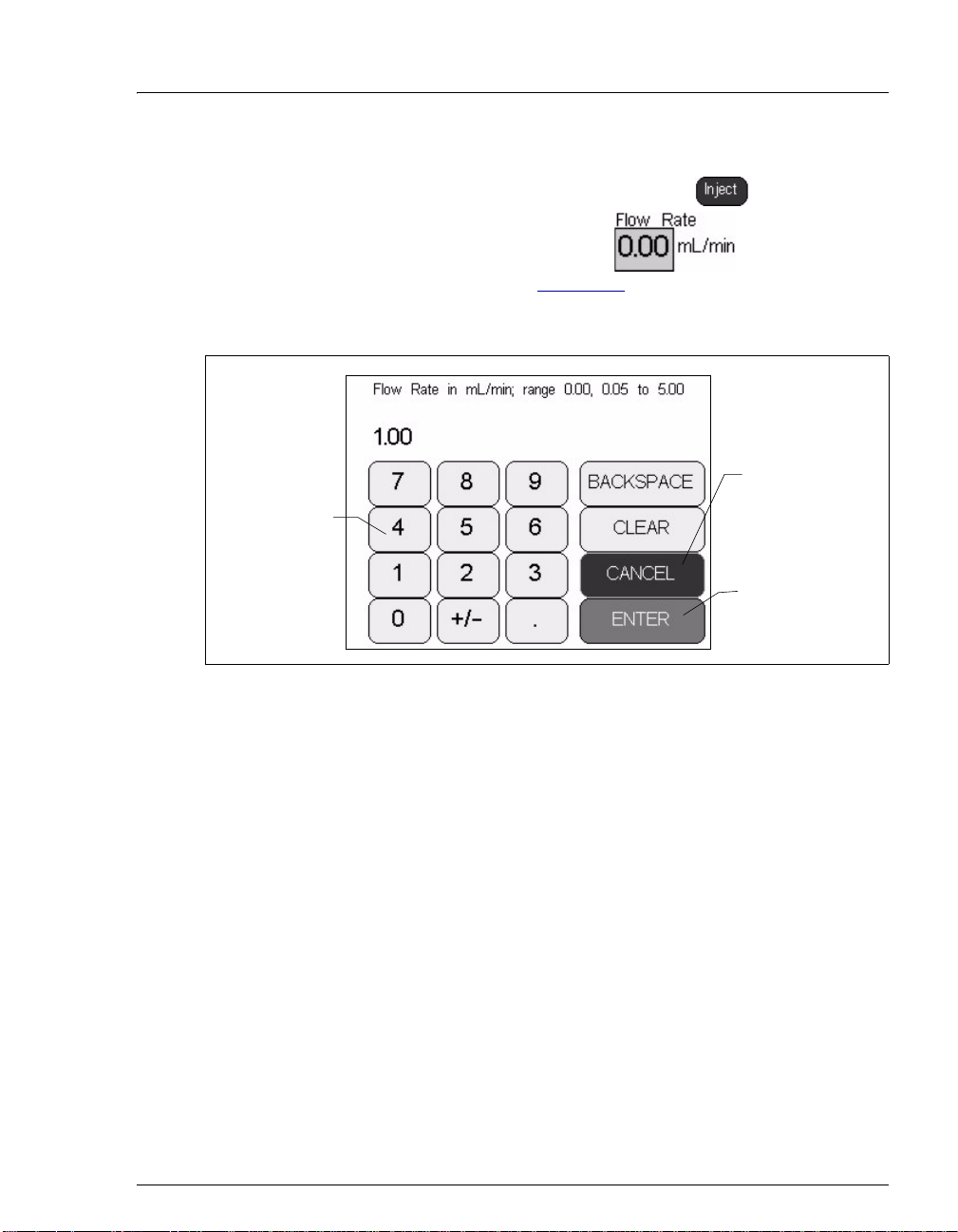
• Selecting a command button changes the button’s appearance to
white text on a dark backgound (for example, ).
• Touching an edit field (for example, ) opens a page
with a number keypad (see Figure 2-3
desired numerical value for the field and then touch the
button.
Touch a
number to
enter the
value.
). Use the keypad to enter the
ENTER
Touch CANCEL
to cancel the
entry and return
to the previous
page.
Touch ENTER to
confirm the
entry and return
to the previous
page.
Figure 2-3. Number Keypad
Doc. 065291-01 3/09 13
Page 26
ICS-2100 Ion Chromatography System
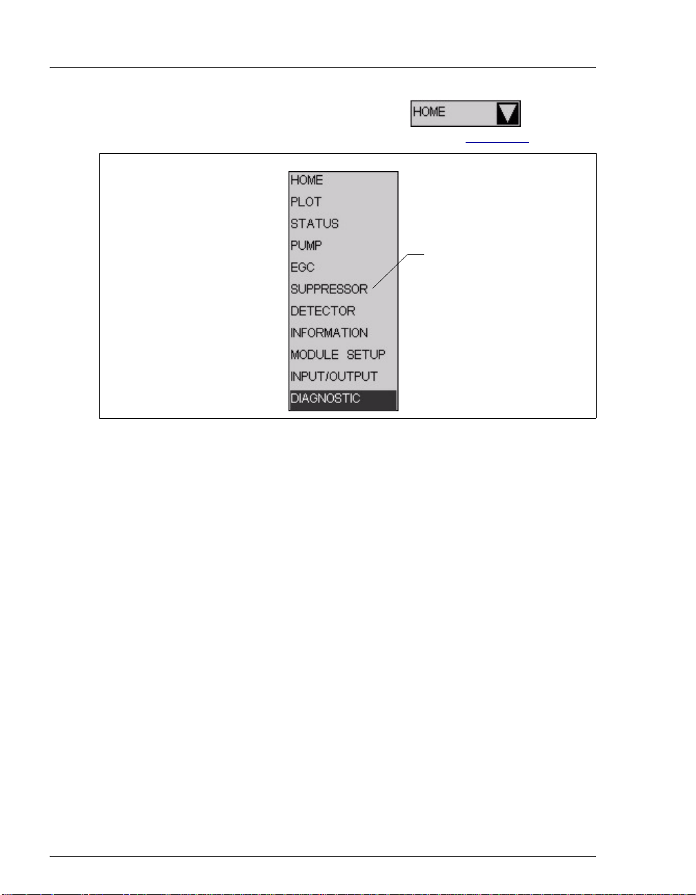
• Touching the page name (for example, ) in the
bottom right corner opens a menu of pages (see Figure 2-4
Figure 2-4. ICS-2100 Touch Screen Menu of Pages
).
Touch a page
name to display
the page.
• Touching a page name on the menu of p ages displays the selected
page. For example, touching
SUPPRESSOR displays the
14 Doc. 065291-01 3/09
Page 27
Touch to
return to the
Home page.
2 • Features
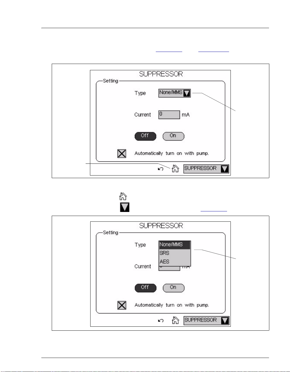
SUPPRESSOR page (see Figure 2-5). See Appendix B for details
about each touch screen page.
Touch to
select a
different
option.
Figure 2-5. Suppressor Page
• Touching returns you to the HOME page.
• Touching opens a list of options (see Figure 2-6).
Figure 2-6. Suppressor Page: Selecting an Option
Touch an
option to
select it.
Doc. 065291-01 3/09 15
Page 28
ICS-2100 Ion Chromatography System
2.1.2 Top Cover
Figure 2-7 illustrates the top cover of the ICS-2100.
EGC, EPM,
CR-TC, and
Auxiliary
Power
Supply
Connectors
Tubing
Chase
(under
connectors)
EGC Service
Area
Figure 2-7. ICS-2100 (Top View)
EluGen
Cartridge
and Holder
Second
EluGen
Cartridge or
Reservoir
Area
Deionized
Water
4 L
Reservoir
Area
EluGen Cartridge and Reservoir
Storage
The top cover holds one or two
®
EluGen
cartridges and up to
two 2-L plastic reservoirs
(P/N 044129) or one 4-L plastic
reservoir (P/N 039164).
EluGen Cartridges
The EluGen cartridges are
installed in holders that fit into
the two back reservoir areas.
See Section 2.4.4
for details
about the eluent generator.
Tubing Chase
The tubing chase under the
EGC and CR-TC connectors
routes tubing from the eluent
reservoir and EGC holder to the
front of the ICS-2100.
EGC, EPM, CR-TC, and Auxiliary Power Supply Connectors
The cable from the EluGen cartridge (EGC) connects to the EGC-1
connector. The cable from the Continuously Regenerated Trap Column
(CR-TC) connects to the
installed, it connects to the
CR-TC connector. If a second EluGen cartridge is
EGC-2 connector. If the second eluent
generator power supply is configured to power an auxiliary electrolytic
device, it connects to the
EGC-2 connector. For details, refer to the ICS-
2100 installation instructions.
When operating with an EGC II K
EluGen Cartridge and the EPM
2CO3
Electrolytic pH Modifier, the EluGen cartridge is typically connected to
the
EGC-1 connector. The pH modifier, which mounts on the side of the
16 Doc. 065291-01 3/09
Page 29

2 • Features
EluGen cartridge holder, is connected to the EGC-2 connector. However,
the connections can be reversed, if desired.
EGC Service Area
The EGC service area holds the cartridge during installation and
replacement. For details, refer to the ICS-2100 installation instructions.
Doc. 065291-01 3/09 17
Page 30
ICS-2100 Ion Chromatography System
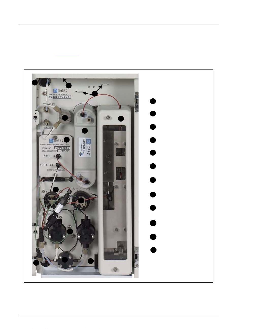
2.1.3 Component Panel
Figure 2-8 shows the use r-accessible components installed on the
component panel behind the ICS-2100 front door.
12
11
10
8
9
6
7
8
7
6
4
5
5
3
3
Pressure Transducer
1
Leak Sensor
2
Pump Heads
3
Injection Valve
4
Auxiliary Valve
5
(Optional)
DS6 Conductivity Cell
6
Suppressor
7
Column Heater and
8
Columns
Eluent Valve
9
Mounting Brackets for
10
Second Suppressor
Screen Adjustment
11
Knob (under display)
Tubing Chase (2)
12
12
1
1
2
2
Figure 2-8. ICS-2100 Component Panel
18 Doc. 065291-01 3/09
Page 31

2 • Features
Pressure Transducer
The pressure transducer measures the system backpressure.
Leak Sensor
The leak sensor is installed in the drip tray at the bottom of the component
panel. If liquid accumulates in the tray, an error message is logged in the
Chromeleon Audit Trail and displayed on the LCD touch screen.
Pump Heads
The ICS-2100 includes a dual-piston serial pump. The flow rate can be set
to 0.00 mL/min or to between 0.05 and 5.00 mL/min. However, for
optimum performance, set the flow rate to between 0.40 and
2.00 mL/min. Setting the flow rate to 0.00 mL/min turns off the pump.
See Section 2.4.3
Injection Valve
The injection valve is a six-port, electrically-activated Rheodyne valve. A
25-μL sample loop (P/N 042857) is installed on the valve at the factory.
See Section 2.4.6
for details about the pump.
for details about valve operation.
Auxiliary Valve (Optional)
The auxiliary valve is a two-position, electrically-activated Rheodyne
valve (6-Port Valve Kit, P/N 069472; 10-Port Valve Kit, P/N 069473).
See Section 2.4.6
DS6 Heated Conductivity Cell
for details about valve operation.
The flow-through conductivity cell measures the electrical conductance
of analyte ions as they pass through the cell. A heat exchanger inside the
cell regulates the temperature, which can be set to between 30 and 55 °C.
For optimum performance, set the temperature to at least 7 °C above the
ambient temperature and 5 °C above the column oven temperature. See
Section 2.4.10
Doc. 065291-01 3/09 19
for details about the cell.
Page 32

ICS-2100 Ion Chromatography System
Suppressor
The suppressor reduces the eluent conductivity and enhances the
conductivity of the sample ions, thereby increasing detection sensitivity.
®
Either an AES
Suppressor, or MMS
the ICS-2100. See Section 2.4.9
Separator and Guard Columns
Both the separator and guard columns are packed with resin and perform
the separation of the sample ions. The main function of the guard column
is to trap contaminants and remove particulates that might damage the
separator column.
Column Heater
The column heater controls the temperature of the separator and guard
columns. The temperature can be set to between 30 and 60 °C; howev er,
it must be set to at least 5 °C above the ambient temperature. See
Section 2.4.8
Atlas Electrolytic Suppressor, SRS® Self-Regenerating
™
MicroMembrane™ Suppressor can be used with
for details about the column heater.
for details about the suppressor.
Eluent Valve
The eluent valve controls the flow from the eluent reservoir. The eluent
valve opens automatically when the pump is started and closes when the
pump is turned off.
Screen Adjustment Knob
Use this knob to change the LCD touch screen contrast.
Tubing Chases
The upper tubing chase routes tubing from the top cover to the component
panel. The lower tubing chase routes tubing from the component panel,
through the interior of the ICS-2100, to the rear panel.
20 Doc. 065291-01 3/09
Page 33

12
2 • Features
2.1.4 Rear Panel
Figure 2-9 illustrates the ICS-2100 rear panel.
Tubing Clips
Analog Output
Connector
Power Switch
USB
Connectors
Main Power
Receptacle
TTL and Relay
Connector Strip
Waste Lines
Figure 2-9. ICS-2100 Rear Panel
Analog Output Connector
The analog output connector outputs conductivity data (as a 0 to 1 V
signal) to an integrator or recording device. For connection and setup
information, refer to the ICS-2100 installation instructions.
USB Connectors
A USB receptacle is provided to allow connection to the Chromeleon
computer. Two USB ports are provided for connecting to other USB
devices. For connection instructions, refer to the ICS-2100 installation
instructions.
Doc. 065291-01 3/09 21
Page 34

ICS-2100 Ion Chromatography System
TTL and Relay Connector
The TTL and Relay connector strip provides two TTL outputs, two relay
outputs, and four TTL inputs. The outputs can be used to control
functions in other TTL- or relay-controllable devices. The inputs can be
used to switch the injection valve position, turn on the pump, perform an
autozero command, and send an event mark to the analog output. See
Section C.1
Tubing Chases
The lower chase routes tubing from the rear panel to the component
panel.
Tubing Clips
The tubing clips hold tubing routed from the top cover in place.
Power Switch
The power switch provides on/off control of power to the ICS-2100.
for connection instructions.
Main Power Receptacle
The power supply cord plugs into the AC power receptacle.
The power supply cord is used as the main disconnec t device. Make
sure the socket-outlet is located near the ICS-2100 and is easily
accessible.
Le cordon d'alimentation principal est utilisé comme dispositif
principal de débranchement. Veillez à ce que la prise de base soit
située/installée près du module et facilement accessible.
Das Netzkabel ist das wichtigste Mittel zur Stromunterbrechung.
Stellen Sie sicher, daß sich die Steckdose nahe am Gerät befindet und
leicht zugänglich ist.
22 Doc. 065291-01 3/09
Page 35

2.2 Flow Schematics
• Figure 2-10 illustrates the liquid flow path when the components required for
producing KOH, LiOH, MSA, or NaOH eluent are installed. The required
components include the corresponding type of EluGen cartridge and a CRTC.
• Figure 2-11 illustrates the liquid flow path when the components required for
producing carbonate/bicarbonate eluent are installed. The required
components include an EGC II K
Electrolytic pH Modifier, and an EGC CO
• Figure 2-12 illustrates the liquid flow path when the components required for
producing carbonate eluent are installed. The required components include an
EGC II K
EluGen Cartridge and an EGC CO3 Mixer.
2CO3
EluGen Cartridge, an EPM
2CO3
Mixer.
3
2 • Features
Doc. 065291-01 3/09 23
Page 36

ICS-2100 Ion Chromatography System
To the pump Degas In
From the
pulse
damper
To the
inject valve
port P(2)
6
EGC II
KOH, LiOH,
MSA, or
NaOH
Inlet Outlet
8
EGC
Degas
17
Degas In
Degas Out
Conductivity
Cell
Cell In
14
Cell Out
EGC Vent
Eluent
Regen In
CR-TC
Suppressor
Regen In
1
Deionized
Water
7
16
Regen Out
Out
Eluent
Column
Heater
13
Heat Exchanger
Eluent Out
15
5
Back-
pressure
Coil
Sample in
Pulse Damper
Valve
S
W
L
9
To waste
L
10
C
P
Pump
Head
Press.
4
Xducer.
3
Pump
Head
2
Eluent
Valve
11
Separator
12
Guard
To waste
18
To Gas
Separator
Assembly
Figure 2-10. ICS-2100 Flow Schematic: KOH, LiOH, MSA, or NaOH Eluent Generation
24 Doc. 065291-01 3/09
Page 37

2 • Features
Flow Description for KOH, LiOH, MSA, or NaOH Eluent Generation
Refer to Figure 2-10 for the flow path number locations.
• Deionized water from the reservoirn flows first through the pump degas
assembly and then through the eluent valve
then pushed through the pressure transducer
pressure. From there, the water flows through a pulse damper
smooths minor pressure variations from the pump to minimize baseline noise.
o to the pumpp. The water is
q, which measures the system
r, which
• Water then flows into the EluGen cartridge (EGC)s, which generates the
programmed concentration of eluent. Eluent exits the cartridge and flows
through the CR-TC
degas tubing assembly
t(which traps ionic contaminants), through the EGC
u, and on to the injection valvev.
• After sample is loaded into the sample loopw and the injection valve is
toggled to the Inject position, eluent passes through the sample loop.
• Th e elu e nt/sa mp le mixture is pumped through the heat exchanger , which
11
heats the mixture to the column heater temperature. The mixture then goes to
the guard and separator columns and through the suppressor .
• From the suppressor, the mixture flows through the cell , where the analytes
12
14
13
are detected. A digital signal is sent to Chromeleon software. Analog output
can be collected simultaneously.
• The mixture flows out of the cell and is recycled back into the suppressor ,
15
where it is the water source for the regenerant chamber.
• Regenerant waste from the suppressor is directed back to the CR-TC , and
then to the EGC degas tubing , where any released hydrogen or oxygen gas
is removed before it is sent to the gas separator assembly and then to waste .
17
16
18
Doc. 065291-01 3/09 25
Page 38

ICS-2100 Ion Chromatography System
To the pump Degas In
6
EGC II
K
2CO3
Inlet Outlet
Eluent Out
1
Deionized
Water
EGC Vent
Sample in
5
Pulse Damper
Valve
S
W
L
10
To waste
8
EGC
Degas
18
Degas In
Degas Out
Conductivity
Cell
Cell In
15
Cell Out
L
11
C
P
Pump
Head
Eluent
Valve
Regen Out
Press.
Xducer.
2
Eluent In
17
Eluent In Regen In
14
Suppressor
16
4
Pump
Head
Back-
pressure
Coil
7
Regen In
Regen Out Eluent Out
3
EPM
Column
Heater
Heat Exchanger
12
13
Guard
9
EGC CO
Separator
3
Mixer
19
To waste
To Gas
Separator
Assembly
Figure 2-11. ICS-2100 Flow Schematic: Carbonate/Bicarbonate Eluent Generation
26 Doc. 065291-01 3/09
Page 39

2 • Features
Flow Description for Carbonate/Bicarbonate Eluent Generation
Refer to Figure 2-11 for the flow path number locations.
• Deionized water from the reservoirn flows first through the pump degas
assembly and then through the eluent valve
then pushed through the pressure transducer
pressure. From there, the water flows through a pulse damper
smooths minor pressure variations from the pump to minimize baseline noise.
o to the pumpp. The water is
q, which measures the system
r, which
• Water then flows into the EluGen cartridge (EGC)s, which generates the
programmed concentration of carbonate eluent. Eluent exits the cartridge and
flows through the EPM
t, which adjusts the eluent concentration to produce
the carbonate/bicarbonate mixture. The mixture flows through the EGC degas
tubing assembly
carbonate/bicarbonate mixture), and then on to the injection valve
u to the EGC CO
Mixerv (to ensure a homogenous
3
w.
• After sample is loaded into the sample loop and the injection valve is toggled
to the Inject position, eluent passes through the sample loop.
• The eluent/sample mixture is pumped through the heat exchanger , which
12
heats the mixture to the column heater temperature. The mixture then goes to
the guard and separator columns and through the suppressor .
• From the suppressor, the mixture flows through the cell , where the analytes
13
15
14
are detected. A digital signal is sent to Chromeleon software. Analog output
can be collected simultaneously.
• The mixture flows out of the cell and is recycled back into the suppressor ,
16
where it is the water source for the regenerant chamber.
• Regenerant waste from the suppressor is directed back to the EPM , and
then to the EGC degas tubing , where any released hydrogen or oxygen gas
is removed before it is sent to the gas separator assembly and then to waste .
18
17
19
Doc. 065291-01 3/09 27
Page 40

ICS-2100 Ion Chromatography System
To the pump Degas In
6
EGC II
K
2CO3
Inlet Outlet
7
EGC
Degas
16
1
Deionized
Water
EGC Vent
Degas In
Column
Heater
Heat Exchanger
8
Degas Out
Conductivity
Cell
Cell In
14
Eluent I n Regen In
13
Suppressor
15
Regen Out Eluent Out
Cell Out
3
EGC CO
Mixer
Separator
Assembly
Sample in
5
Pulse Damper
Valve
S
10
W
L
To waste
11
L
C
P
9
Pump
Head
Eluent
Valve
Press.
4
Xducer.
3
Pump
Head
2
Back-
pressure
Separator
12
Guard
Coil
Figure 2-12. ICS-2100 Flow Schematic: Carbonate Eluent Generation
To waste
17
To Gas
28 Doc. 065291-01 3/09
Page 41

2 • Features
Flow Description for Carbonate Eluent Generation
Refer to Figure 2-12 for the flow path number locations.
• Deionized water from the reservoirnflows first through the pump degas
assembly and then through the eluent valve
then pushed through the pressure transducer
pressure. From there, the water flows through a pulse damper
smooths minor pressure variations from the pump to minimize baseline noise.
o to the pumpp. The water is
q, which measures the system
r, which
• Water then flows into the EluGen cartridge (EGC)s, which generates the
programmed concentration of carbonate eluent. Eluent exits the cartridge and
flows through the EGC degas tubing assembly
EGC CO
on to the injection valve
Mixeru (to ensure a homogenous eluent concentration), and then
3
v.
t. Eluent then goes to the
• After sample is loaded into the sample loopw and the injection valve is
toggled to the Inject position, eluent passes through the sample loop.
• The eluent/sample mixture is pumped through the heat exchanger , which
11
heats the mixture to the column heater temperature. The mixture then goes to
the guard and separator columns and through the suppressor .
• From the suppressor, the mixture flows through the cell , where the analytes
12
14
13
are detected. A digital signal is sent to Chromeleon software. Analog output
can be collected simultaneously.
• The mixture flows out of the cell and is recycled back into the suppressor ,
15
where it is the water source for the regenerant chamber.
• Regenerant waste from the suppressor is directed back to the EGC degas
tubing , where any released hydrogen or oxygen gas is removed before it is
sent to the gas separator assembly and then to waste .
16
17
Doc. 065291-01 3/09 29
Page 42

ICS-2100 Ion Chromatography System
2.3 Chromeleon and Chromeleon Xpress
The ICS-2100 is controlled by a PC configured with Chromeleon
Chromatography Management System or Chromeleon Xpress. Chromeleon
Chromatography Management System provides complete instrument control, data
acquisition, and data management. Chromeleon Xpress provides real-time control
and monitoring of Dionex chromatography instruments, bu t does not inclu de data
management capabilities.
2.3.1 The Panel Tabset
The Chromeleon and Chromeleon Xpress panel tabset provides a
centralized location for controlling system functions. A panel tabset for
an ICS-2100 system typically includes the following Control panels:
• An ICS-2100 Control panel (see Figure 2-13) provides access to ICS-
2100 functions. The label on the tab for this panel is the name of the
timebase in which the ICS-2100 is configured.
Figure 2-13. ICS-2100 Control Panel on the Panel Tabset
30 Doc. 065291-01 3/09
Page 43

2 • Features
• A Sequence Control panel let s you define and run sequences (groups
of sample injections to be analyzed in the order in which they are
listed).
• A Status panel shows the overall system status.
• An Autosampler panel (included if the ICS-2100 is connected to an
AS, AS-DV, or AS-HV Autosampler) provides access to autosampler
functions.
To open the panel tabset, use one of the methods below:
• If Chromeleon is installed,
start Chromeleon and click
the Default Panel Tabset
toolbar button, or select
View > Default Panel
Tabset.
• If Chromeleon Xpress is
installed, start the application; this automatically displays the ICS2100 panel tabset.
2.3.2 Software Control Modes
Two modes of software control are available: direct control and
programmed control.
• With direct control, you select operating parameters and commands
from the Control panels. Direct control commands are executed as
soon as they are entered. See Section 3.11.2
control.
for details about direct
• With programmed control, you create a list of control commands to
be executed in chronological order. Programs can be created
automatically (with the help of a software wizard). See Section 3.11.3
for details about programmed control.
2.3.3 System Wellness
System Wellness monitors the overall “health” of a chromatographic
system. It provides built-in diagnostic and calibration features that help
prevent unscheduled system shutdowns and assure reliable operation of
system devices. For details about System Wellness, see Section 5.1
Doc. 065291-01 3/09 31
.
Page 44

ICS-2100 Ion Chromatography System
2.4 System Component Details
This section provides details about ICS-2100 system components, including the
vacuum degas assembly, pump, eluent generator, injection valve, column heater,
suppressor, auxiliary power supply, and conductivity cell.
2.4.1 Vacuum Degas Assembly (Optional)
The vacuum degas assembly provides online eluent degassing at the time
and duration specified by the user. The assembly, which must be installed
in the ICS-2100 at the factory, consists of:
• A single-channel degas chamber (with degas membranes) with
internal capacity of 17 mL
• A dual-stage diaphragm vacuum pump
• A solenoid valve
• An on-board vacuum sensor
• The electronics required to operate the vacuum pump
• Tubing, fittings, and other accessories
By default, the ICS-2100 monitors the degas pressure reading and turns
the degas pump on and off as needed. Different degas operating modes
can be selected from the touch screen
from Chromeleon.
To select the degas operating options, open the Chromeleon Server
Configuration program, right-click the ICS-2100 device in the timebase,
and select Properties.
PUMP page (see Section B.7) or
32 Doc. 065291-01 3/09
Page 45

2 • Features
Select the Options tab (see Figure 2-14).
.
Figure 2-14. Server Configuration Properties: Degas Options
Degas Options
• Always Off: The degas pump is always off.
• Always On: The degas pump is always on. This setting is for test
purposes by a Dionex Service Representative. Do not use this setting
for routine operation.
• Cycle: The degas pump cycles on and off according to the times
specified in the
long the degas pump runs during a cycle.
between cycles.
Cycle On and Off fields. Cycle On specifies for how
Cycle Off specifies the time
• Monitor: (default mode) The ICS-2100 monitors the degas pressure
reading and turns the degas pump on and off as required.
Doc. 065291-01 3/09 33
Page 46

ICS-2100 Ion Chromatography System
2.4.2 Eluent V alve
Figure 2-15. Eluent Valve
2.4.3 Pump
The eluent valve controls the flow from
the eluent reservoir. The valve opens
automatically when the pump is started
and closes when the pump is turned off.
The valve can also be opened and closed
manually from the Chromeleon Control
panel (see Section 2.3.1
screen
PUMP page (see Section B.7).
) or the touch
This lets you perform service
procedures on pump components
without eluent leaks occurring.
The ICS-2100 pump is a microprocessor-based isocratic eluent delivery
system. Its variable speed, dual-piston series design ensures pulse-free
pumping for the most demanding applications.
Primary Pump Head
The primary pump head pumps eluent into the secondary head (see
Figure 2-16
). The check valves, which prevent reverse flow through the
pump, are located on the bottom (inlet) and top (outlet) of the primary
pump head. The priming valve is on the front of the pump head.
To open the priming valve, turn the knob one-quarter to one-half turn
counterclockwise. When the priming valve is open, liquid can flow into
and out of the primary pump head via the port in the front of the valve.
NOTE The priming valve must be open when the pump is
being primed with a syringe or with isopropyl
alcohol. For detailed priming instructions, see
Section 5.16
.
34 Doc. 065291-01 3/09
Page 47

Secondary
Pump Head
2 • Features
Outlet Check
Valve
Primary
Pump Head
Waste Valve
Pressure
Transducer
Priming
Valve
Inlet Check
Valve
Figure 2-16. ICS-2100 Pump Components
Secondary Pump Head
The secondary pump head delivers eluent to the remainder of the
chromatography system (the injection valve, column, and detector). The
waste valve is located on the front of the secondary pump head (see
Figure 2-16
).
To open the waste valve, turn the knob one-quarter to one-half turn
counterclockwise. When the waste valve is in the open position, all pump
flow is directed to waste.
NOTE The waste valve must be open when the pump is
being primed using the Prime button. For detailed
priming instructions, see Section 5.16
.
Doc. 065291-01 3/09 35
Page 48

ICS-2100 Ion Chromatography System
Pressure Transducer
Flow exiting the secondary pump head is directed to the pressure
transducer (see Figure 2-16
Pressure readings indicate that the pumping system is delivering smooth,
accurate flow. Pressure readings can be monitored from the Chromeleon
Control panel or the touch screen
The system pressure should remain consistent (no more than a 3%
difference from one pressure reading to the next). High and low pressure
limits can be used to stop the pump flow if a limit is exceeded. The
pressure limits can be set from Chromeleon (in the Server Configuration
or in the control program) or from the touch screen
Section B.7
). See Section 4.2 for troubleshooting information if a
pressure limit is exceeded.
Pulse Damper
Flow output from the pressure transducer continues to the pulse damper,
which smooths minor pressure variations. From there, flow is directed to
the injection valve and then to the remainder of the chromatography
system.
), which measures the system pressure.
HOME page.
PUMP page (see
Piston Seal Wash
The pump includes a piston seal wash assembly that can be set up to
continuously rinse the back of the piston seals to remove salt crystals and
prolong the life of the seals. To use this feature, an external water source
must be connected. For connection instructions, refer to the ICS-2100
installation instructions.
For continued protection of the pump, replace the piston rinse seals (see
Section 5.7
) and O-rings in the seal wash assembly every 6 months, or
whenever you replace the main piston seals for the ICS-2100 pump.
36 Doc. 065291-01 3/09
Page 49

2.4.4 Eluent Generator
The eluent generator produces high-purity eluents online, using only
deionized water as the carrier. The eluent generator consists of an eluent
generator cartridge (EGC) that generates the eluent, and a high-pressure
degas tubing assembly that removes electrolysis gases created during
eluent generation.
NOTE A gas separator waste tube (P/ N 0 45460) should
be connected to the system waste line during
installation (see Section B.10.1
Several types of EluGen cartridges are available for use with the ICS2100 (see Table 2-1)
electrolyte concentrate solution for eluent generation.
EluGen Cartridge Part Number Function
EGC II K2CO3
EluGen Cartridge
EGC II KOH
EluGen Cartridge
EGC II LiOH
EluGen Cartridge
EGC II MSA
EluGen Cartridge
EGC II NaOH
EluGen Cartridge
2 • Features
).
. Each cartridge contains 900 mL of the appropriate
058904 Generates carbonate eluent for
anion exchange separations. Note:
Produces a carbonate/bicarbonate
mixture when installed with the
EPM Electrolytic pH Modifier
(P/N 063175) and EGC CO
Mixer (P/N 061686).
058900 Generates hydroxide eluent for
anion exchange separations.
058906 Generates lithium hydroxide
eluent for anion exchange
separations.
058902 Generates methanesulfonic acid
eluent for cation exchange
separations.
058908 Generates sodium hydroxide
eluent for anion exchange
separations.
3
Table 2-1. EluGen Cartridge Types for the ICS-2100
For more information, refer to the EluGen cartridge manual. The manual
is included on the Dionex Reference Library CD-ROM (P/N 053891).
Doc. 065291-01 3/09 37
Page 50

ICS-2100 Ion Chromatography System
You can select the concentration of eluent to be generated from either the
Chromeleon Control panel or from the touch screen
Section B.4
The allowable eluent concentration depends on several factors: the flow
rate, suppressor type, EluGen cartridge type, and cartridge configuration.
For details, refer to Table 2-2
Single-Cartridge Configuration
In the single-cartridge configuration, the ICS-2100 contains one EluGen
cartridge.
EluGen Cartridge Eluent Concentration Range
K2CO
KOH 0.1 to 100 mM at 0.1 to 1.0 mL/min flow
LiOH 0.1 to 80 mM at 0.1 to 1.0 mL/min flow
MSA 0.1 to 100 mM at 0.1 to 1.0 mL/min flow
NaOH 0.1 to 100 mM at 0.1 to 1.0 mL/min flow
).
and Table 2-3.
3
0.1 to 15 mM at 0.1 to 1.0 mL/min flow
0.1 to X mM at 1.0 to 2.0 mL/min flow
where X = 15/flow in mL/min
0.1 to X mM at 1.0 to 3.0 mL/min flow
where X = 100/flow in mL/min
0.1 to X mM at 1.0 to 3.0 mL/min flow
where X = 80/flow in mL/min
0.1 to X mM at 1.0 to 3.0 mL/min flow
where X = 100/flow in mL/min
0.1 to X mM at 1.0 to 3.0 mL/min flow
where X = 100/flow mL/min
HOME page (see
Table 2-2. Eluent Concentration Ranges for Single-Cartridge
Configurations
Linked Dual-Cartridge Configuration
In the linked dual-cartridge configuration, the ICS-2100 contains two
EluGen cartridges (or one EluGen cartridge and an EPM) that perform as
one cartridge. Note that the allowable eluent concentration for a linked
cartridge is less than when the cartridge is defined as independent. For
38 Doc. 065291-01 3/09
Page 51

2 • Features
details, refer to the EluGen cartridge manual. Cartridge manuals are
included on the Dionex Reference Library CD-ROM (P/N 053891).
EluGen
Cartridges
K2CO3/EPM
Electrolytic
pH Modifier
KOH/KOH
KOH/MSA
KOH/NaOH
MSA/MSA
MSA/NaOH
NaOH/NaOH
LiOH/LiOH 0.1 to 40 mM at 0.1 to 1.0 m L/ mi n
Eluent Concentration Range Comment
0.1 to 15 mM at 0.1 to 1.0 mL/min
flow
0.1 to X mM at 1.0 to 2.0 mL/min
flow
X = 15/flow
0.1 to 50 mM at 0.1 to 1.0 mL/min
flow
0.1 to X mM at 1.0 to 3.0 mL/min
flow
X = 50/flow
flow
0.1 to X mM at 1.0 to 3.0 mL/min
flow
X = 40/flow
The total of the eluent
concentrations from
both the EluGen
cartridge and the EPM
must not exceed the
specified range. The
EPM concentration
must not exceed
10 mM. See
“
Generating
Carbonate/Bicarbonate
Eluent” on page 41 for
details.
The eluent
concentration range for
each cartridge is cut by
50%.
The eluent
concentration range for
each cartridge is cut by
50%.
Table 2-3. Eluent Concentration Ranges for Linked
Dual-Cartridge Configurations
EluGen Cartridge Holder
The EluGen cartridge is installed in a cartridge holder, which mounts on
the ICS-2100 top cover (see Figure 2-7
). The cartridge holder also houses
the high-pressure degas tubing assembly.
The ICS-2100 can control up to two EluGen cartridges. However, when
operating with an EGC II K
EluGen Cartridge and the pH Modifier,
2CO3
only one cartridge can be installed, because the pH Modifier must be
connected to the other EGC power supply (
Doc. 065291-01 3/09 39
EGC-1 or EGC-2).
Page 52

ICS-2100 Ion Chromatography System
Tubing and fittings for plumbing the cartridge, degas assembly, CR-TC,
and EPM are included with the holder. For connection instructions, refer
to the ICS-2100 installation instructions.
Backpressure Coil (Optional)
The EluGen cartridge requires at least 14 MPa (2000 psi) of system
backpressure for removal of electrolysis gas from the eluent produced by
the cartridge. A system backpressure of 16 MPa (2300 psi) is ideal.
If necessary, increase the system backpressure by installing a
backpressure coil between the injection valve and the EluGen cartridge
OUTLET port. For details, refer to the ICS-2100 installation instructions.
Continuously Regenerated Trap Column (CR-TC)
The CR-TC is a high pressure electrolytically-regenerated trap column.
The CR-TC is designed to remove anio nic or cationic contaminants in the
eluent or deionized water and to reduce drift during gradient separations.
Two versions of the CR-TC can be used with the ICS-2100:
• CR-ATC (Continuously Regenerated Anion Trap Column,
P/N 060477)
• CR-CTC (Continuously Regenerated Cation Trap Column,
P/N 060478)
For more information, refer to the CR-TC manual. The manual is
included on the Dionex Reference Library CD-ROM (P/N 053891).
NOTE The IonPac® ATC-HC Trap Column (P/N 059604)
or IonPac CTC-1 Trap Column (P/N 040192) can be
used with the ICS-2100. However, both IonPac trap
columns require off-line chemical regeneration.
Contact Dionex for more information.
40 Doc. 065291-01 3/09
Page 53

2 • Features
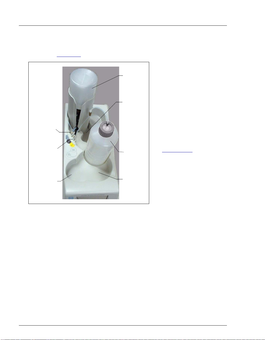
EPM Electrolytic pH Modifier and EGC CO
Mixer
3
The EGC II K2CO3 EluGen
Cartridge can be used with an
EPM Electrolytic pH Modifier
(P/N 063175) (see Figure 2-17
and an EGC CO
Mixer
3
)
EluGen
Cartridge
EPM
(P/N 061686 ) to produce a
carbonate/ bicarbonate mixture.
The carbonate/bicarbonate
mixture is used with carbonatebased IonPac columns for
anion exchange separations.
Figure 2-17. ICS-2100 with an EluGen Cartridge and EPM Installed
After the cartridge generates carbonate eluent, the pH Modifier adjusts
the eluent concentration to produce the carbonate/bicarbonate mixture.
The EGC CO
solution of electrolytically-generated K
Mixer provides enough mixing to produce a homogenous
3
and KHCO3 eluent.
2CO3
For more information about these products, refer to the EluGen cartridge
manual. Cartridge manuals are included on the Dionex Re ference Libra ry
CD-ROM (P/N 053891).
Generating Carbonate/Bicarbonate Eluent
If a K2CO3 EluGen cartridge and an EPM Electrolytic pH Modifier are
installed (connected to EGC-1 and EGC-2, respectively), set EGC-1 to
the concentration of K
to the concentration of KHCO
K
/KHCO3 eluent mixture, the K2CO3 cartridge must generate the
2CO3
required for your application and set EGC-2
2CO3
required. In order to achieve the desired
3
total of the two setpoint concentrations.
For example, for a 3.50 mM K
/1.00 mM KHCO3 eluent, set EGC-1
2CO3
to 3.50 mM and EGC-2 to 1.00 mM. When the eluent is generated, the
K
Doc. 065291-01 3/09 41
cartridge generates 4.50 mM K2CO3, which is then modified by
2CO3
Page 54

ICS-2100 Ion Chromatography System
p
p
n
the EPM to achieve the desired 3.50 mM K2CO3/1.00 mM KHCO
mixture.
2.4.5 Auxiliary Power Supply (Optional)
The EGC-2 power supply can be configured as an auxiliary power supply
for the operation of an electrolytic device such as a water purifier. The
power supply operates in constant current mode and can be configured
from 0 to 200 mA, with a maximum voltage of 35 V.
2.4.6 Injection Va lve
The injection valve (P/N 057968) is a six-port, electrically-activated
valve. A 25-μL sample loop (P/N 042857) is installed on the valve at the
factory.
The valve has two operating positions: Load and Inject (see Figure 2-18
Sample In
Sample
Loop
LOAD POSITION
To Column
Sample In
Sample
Loop
3
).
INJECT POSITION
To Colum
To Waste
From Pum
To Waste
From Pum
Figure 2-18. Injection Valve Flow Schematics
Eluent flows through either the Load or Inject path, depending on the
valve position.
• In the Load position, sample is loaded into the sample loop, where it
is held until injection. Eluent flows from the pump, through the valve,
and to the column, bypassing the sample loop. Sample flows from the
42 Doc. 065291-01 3/09
Page 55

2 • Features
syringe or automated sampler line (if installed), through the valve,
and into the sample loop. Excess sample flows out to waste.
• In the Inject position, sample is swept to the column for analysis.
Eluent flows from the pump, through the sample loop, and on to the
column, carrying the contents of the sample loop with it. Section 3.10
describes how to inject samples.
Figure 2-19
shows the injection valve connections. The injection valve is
plumbed at the factory with all tubing and fittings for connection to the
™
pump, injection port, column, and waste. A 25-μL PEEK
sample loop
(P/N 042857) is installed between ports L (1) and L (4). Dionex offers
sample loops in various sizes. If necessary, the pre-installed 25-μL loop
can be replaced with a loop that has a different sample injection volume.
Figure 2-19. Injection Valve Plumbing
NOTE The EluGen cartridge requires at least 14 MPa
(2000 psi) of system backpressure for removal of
electrolysis gas from the eluent produced by the
cartridge. A system backpressure of 16 MPa (2300 psi) is
ideal.
If the system backpressure is too low, install a
backpressure coil. Connect one end of the backpressure
coil to port P (2) on the injection valve; connect the other
end to the
for details.
Doc. 065291-01 3/09 43
TO INJ VALVE IN - P line. See Section B.17.1
Page 56

ICS-2100 Ion Chromatography System
2.4.7 Auxiliary Valve (Optional)
The auxiliary valve is a high-pressure Rheodyne valve. The electricallyactivated, 2-position PEEK valve is offered in both 6-port and 10-port
models (6-Port Valve Kit, P/N 069472; 10-Port Valve Kit, P/N 069473).
The auxiliary valve enables a variety of sample preparation activities,
including:
• Online filtration
• Matrix elimination (for example, the removal of high backgrounds of
chloride or organic material)
• Concentrator-based techniques
• Conditional injections (large loop/small loop applications where the
data system monitors sample concentration and reinjects the sample,
using the smaller loop, if the concentration is too high)
• AutoNeutralization
™
• Matrix diversion prior to MS (mass spectrometry) detection
For more information, refer to Installing the ICS-1100/ICS-1600/ICS2100 Auxiliary Valve (Document No. 065288). The manual is provided in
the Auxiliary Valve Kit.
44 Doc. 065291-01 3/09
Page 57

2.4.8 Column Heater
2 • Features
The column heater provides temperature
control for the separator and guard column.
The heater temperature can be set to between
30 °C and 60 °C. However, the set
temperature must be at least 5 °C above the
ambient temperature. A thermistor mounted
in the heater block monitors the temperature.
Setting the temperature to 0 °C turns off the
column heater.
If the temperature exceeds 65 °C, the
column heater is shut off and the error
message “Column heater exceeds safe
temperature.” is displayed on the touch
screen and in the Chromeleon Audit Trail.
See Section 4.2
information.
for troubleshooting
For best results with 2-mm columns, a
microbore heat exchanger (P/N 060943)
should be installed in the column heater (see
Section 5.13
). The tubing connections
between the injection valve and column heat
exchanger, guard column and separator
column, and separator column to detector
cell should all use red 0.125-mm, 0.005-in
ID PEEK tubing (P/N 044221), rather than
the standard black tubing.
Figure 2-20. Column Heater
Doc. 065291-01 3/09 45
Page 58

ICS-2100 Ion Chromatography System
2.4.9 Suppressor
The suppressor reduces the eluent conductivity and enhances the
conductivity of the sample ions, thereby increasing detection sensitivity.
Either an Atlas Electrolytic Suppressor, Self-Regenerating Suppressor, or
MicroMembrane Suppressor can be used with the ICS-2100.
For details about any of the suppressors or for information about selecting
a suppressor for your application, refer to the suppressor manuals. The
manuals are on the Dionex Reference Library CD-ROM (P/N 053891).
2.4.10 DS6 Heated Conductivity Cell
The flow-through conductivity cell measures the electrical conductance
of analyte ions as they pass through the cell. Two passivated 316 stainless
steel electrodes are permanently sealed into the PEEK cell body. The cell
design provides efficient sweep-out, low volume (1
dispersion. Temperature control and compensation help ensure good peak
reproducibility and baseline stability.
Temperature Control
μL), and low
Temperature directly affects the conductivity of a solution. For example,
laboratory heating and air conditioning systems can cause a regular slow
cycling in the baseline. This, in turn, can affect the reproducibility of an
analysis. The higher the conductivity, the more pronounced the effect.
In ion analysis, the effect of temperature variation is minimized by
suppressing eluent conductivity. To further reduce the effect of
temperature variation, a heater inside the cell regulates the temperature.
The cell heater can be set to between 30 °C and 55 °C. The set
temperature must be at least 7 °C above the ambient temperature. Setting
the cell temperature to 0 °C turns off the cell heater.
Temperature Compensation
Built-in preset temperature compensation of 1.7% per °C helps minimize
changes in the baseline or in peak heights when the operating temperature
is different from the temperature at which the cell was calibrated.
46 Doc. 065291-01 3/09
Page 59

2 • Features
DS6 Heated Conductivity Cell Components
The cell front cover provides CELL IN and CELL OUT fittings for
connecting the cell to the suppressor (see Figure 2-8
components are mounted behind the component panel. To replace, the cell
remove the screws on the cell front cover and pull the entire cell assembly
out through the component panel. See Section 5.10
instructions.
). The remaining cell
for cell replacement
Doc. 065291-01 3/09 47
Page 60

ICS-2100 Ion Chromatography System
48 Doc. 065291-01 3/09
Page 61

3 • Operation and Maintenance
This chapter describes routine operating and maintenance procedures for the ICS-
2100.
The ICS-2100 is designed for IC (ion chromatography) applications and should
not be used for any other purpose. Operation of the ICS-2100 in a manner not
specified by Dionex may result in personal injury.
3.1 Operation Overview
Figure 3-1 illustrates the basic steps for routine operation of the ICS-2100.
Power up the system
Start Chromeleon
Set up the reservoir
(or RFIC-ER system )
Check all
connections
Prime the pump
Set operating
conditio n s
Equilibrate the
system
Prepare samples
Verify operating
status
Process samples
Figure 3-1. Operation Flow Chart
Doc. 065291-01 3/09 49
Page 62

ICS-2100 Ion Chromatography System
Sample Processing Overview
Samples can be run manually (one at a time), or they can be grouped and run
automatically in batches. Figure 3-2
sample processing.
shows the typical steps for manual and batch
Manual Sample
Processing
Using the Front Panel
Load the sample Load the sample
Autozero
Inject the sample
(Optional)
Record data from
the analog output*
*A third-party recording
device must be connected
to the analog output.
Manual Sample
Processing
Using Chromeleon
Start data
acquisition
Autozero
Inject the sample
Stop data
acquisition
(Optional)
Save the manual
sequence data
Batch Sample
Processing
Using Chromeleon
Create a sequence
(Sequence Wizard)
Add the sequence
to the batch
Start the batch
Figure 3-2. Sample Processing Overview
50 Doc. 065291-01 3/09
Page 63

3 • Operation and Maintenance
3.2 Turning On the System Power
Power
Switch
Press the power switch on the ICS2100 rear panel (see Figure 3-3
) to
turn on the system power. Table 3-4
shows the ICS-2100 conditions at
power-up.
Also turn on the power to the
computer and the autosampler (if
used).
Figure 3-3. ICS-2100 Rear Panel
Feature Power-Up Condition
Pump Off
Injection valve Load position
Cell Reading current value
Suppressor Off*
Cell heater Set to the last value used. The default when the ICS-2100
is turned on for the first time is 35 °C.
Column oven temperature Set to the last value used. The default when the ICS-2100
is turned on for the first time is 30 °C.
Eluent generator Off*
CR-TC Off
EPM
* When you start the suppressor, eluent generator, or EPM, the value used last is restored.
Table 3-4. ICS-2100 Power-Up Conditions
Doc. 065291-01 3/09 51
Off
*
Page 64

ICS-2100 Ion Chromatography System
3.3 Connecting to Chromeleon
NOTE If you are beginning operation of an ICS-2100 that has
not been configured in a timebase, refer to the ICS-2100
installation instructions for Chromeleon setup
instructions.
1. Turn on the PC.
2. Start the Chromeleon Server, if it is not already running.
a. Check the Chromeleon Server Monitor icon on the Windows taskbar.
• When the server is running, the icon is gray .
• When the Server is not running, the icon is crossed out in red ).
To start the server, right-click the icon and select Start Server.
b. If the Server Monitor icon is not on the Windows taskbar, click Start >
All Programs > Chromeleon > Server Monitor. The Server Monitor
opens. Click Start to start the server.
3. To start the Chromeleon client, click Start and select All Programs >
Chromeleon > Chromeleon.
4. If Chromeleon is installed, the main
window and Browser appear.
Display the panel tabset by
selecting View > Default Panel
Tabset or by clicking the Default
Panel Tabset toolbar button.
If Chromeleon Xpress is installed,
starting the application automatically displays the panel tabset.
5. To display the ICS-2100 Control panel, click the tab labeled with the ICS2100 timebase name (see Figure 3-4
52 Doc. 065291-01 3/09
).
Page 65

3 • Operation and Maintenance
Figure 3-4. ICS-2100 Control Panel on the Chromeleon Panel Tabset
Doc. 065291-01 3/09 53
Page 66

ICS-2100 Ion Chromatography System
3.4 Set Up the Eluent Reservoir
The ICS-2100 does not require pressurized reservoirs. However, if eluent is
manually degassed or is sensitive to contamination, Dionex recommends
pressurizing the reservoir with helium or nitrogen.
The air regulator accessory bracket and other items needed for pre ssurizing the
eluent reservoir must be ordered separately (P/N 060054). For more information,
refer to the ICS-2100 installation instructions.
3.4.1 Filter the Deionized Water
Filtering removes small particulates in the deionized water that may
contaminate the pump check valves and cause erratic flow rates or loss of
prime. An end-line filter (P/N 045987) is provided in the ICS-2100 Ship
Kit (P/N 064375) for this purpose.
Install the end-line filter on the end of the deionized water line, inside the
reservoir. Verify that the end of the filter extends to the bottom of the
reservoir and that the filter is submerged in deionized water . This preven ts
air from being drawn through the lines.
3.4.2 Fill the Reservoir
Fill the reservoir with ASTM filtered, Type I (18-megohm) deionized
water.
3.4.3 Set the Eluent Level
After filling the reservoir, enter the volume of liquid in the reservoir in
one of the following locations:
• On the HOME page in the Eluent Level field (see Figure 3-5)
• In the Eluent Bottle field in the Pump Settings window (accessed
from the ICS-2100
Figure 3-4
The ICS-2100 determines the eluent usage by monitoring the flow rate
and the length of time the pump is on, and updates the Eluent Bottle
volume as the eluent is depleted. A warning appears if the level falls
below 200 mL. Warnings are repeated at 100 mL and 0 mL.
54 Doc. 065291-01 3/09
)
Control panel on the Chromeleon panel tabset (see
Page 67

3 • Operation and Maintenance
In order for the level displayed in the Eluent Bottle box and gauge to
be accurate, you must enter the level when the reservoir is fil led. The
ICS-2100 does not automatically detect when the reservoir is filled,
nor when it is empty.
Enter the volume of
liquid in the reservoir
Enter the volume
of liquid in the
reservoir (in liters)
Note: The Eluent Level
field is updated as the
liquid is depleted.
Figure 3-5. Home Page: Setting the Eluent Level
Note: The Eluent
Bottle field and slider
gauge are updated as
the liquid is depleted.
Figure 3-6. Pump Settings Windows: Setting the Eluent Level
The STATUS page (see Figure 3-7) also displays the amount of liquid
remaining in the reservoir and an estimate of how many hours remain
before the eluent reservoir is empty.
Doc. 065291-01 3/09 55
Page 68

ICS-2100 Ion Chromatography System
See Section B.6 for details about the STATUS PAGE.
Figure 3-7. Status Page
3.4.4 Connect the Reservoir
If it is not already connected,
connect the
OUT
line from the reservoir
cap to the
which extends from the
plumbing and cable chase on
the top of the ICS-2100 (see
Figure 3-8
ELUENT BOTTLE
ELUENT IN line,
).
ELUENT
BOTTLE
OUT
ELUENT
IN
Figure 3-8. Reservoir Connections
56 Doc. 065291-01 3/09
Page 69

3.5 Check All Connections
d
(
)
1. Make sure the eluent reservoir is filled and the tubing connecting the reservoir
to the ICS-2100 tubing is securely connected (see Figure 3-8
2. Make sure the eluent generator electrical cable (blue) is connected to the
EGC-1 connector.
3 • Operation and Maintenance
).
3. Make sure the CR-TC electrical cable (black) is connected to the
connector.
3.6 Prime the Pump
If you changed eluent or if the eluent lines are dry, prime the lines first
with a syringe before following the procedure below to prime the
pump. See Section 5.16.1
syringe.
1. Verify that the priming valve on the primary pump head (see Figure 3-9) is
closed (turned all the way clockwise).
2. Open the waste valve on the secondary pump head by turning the knob one-
quarter to one-half turn counterclockwise. Opening the valve directs the
eluent flow path to waste and eliminates backpressure.
Secondary
Pump Head
Waste Valve
(open)
CR-TC
for instructions on priming the lines with a
Primary
Priming Valve
close
Pump Hea
Figure 3-9. Priming the Pump
3. Press
Doc. 065291-01 3/09 57
Prime on the Chromeleon Control panel or the ICS-2100 touch screen
HOME page. Confirm that the waste valve is open by pressing OK when the
Page 70

ICS-2100 Ion Chromatography System
reminder message appears. The pump will begin pumping at approximately
3mL/min.
4. Continue priming the ICS-2100 until all air and previous eluent are purged
and no air bubbles are exiting the waste line.
5. Press
Pump Off.
6. Close the waste valve. Do not overtighten. The pump is now ready for
operation.
3.7 Set System Operating Conditions
NOTE This section is an overview of the steps needed to start
up the system and begin running samples. Actual
operating parameters (flow rate, cell heater
temperature, suppressor current, etc.) depend on the
application to be run. Refer to the column manual for
the required parameters for your application.
Set or verify system operating parameters from either the Chromeleon Control
panel or from the touch screen
automatically by loading a Chromeleon sequence.
NOTE Clicki ng the System Startup button on the Chromeleon
Control panel starts the pump and suppressor. The flow
rate and suppressor current settings that were in effect
when the system was shut down are restored.
HOME page. Operating parameters can also be set
NOTE Clicki ng the System Startup button on the Chromeleon
Control panel starts the pump, suppressor, eluent
generator, and CR-TC. The flow rate, suppressor
current, and eluent concentration settings that were in
effect when the system was shut down are restored.
1. Verify that the pump is on and set to the correct flow rate.
2. Verify that the suppressor current is on and that the setting is correct.
3. Verify that the eluent generator is turned on and the correct concentration is
set. Verify that the CR-TC is turned on.
4. Verify that the cell heater is set to the correct value.
58 Doc. 065291-01 3/09
Page 71

3 • Operation and Maintenance
5. Verify that the column heater is set to the correct value.
Automatically Turning on the Suppressor and Eluent Generator
You can set up the ICS-2100 to turn on the suppressor, eluent generator, and
CR-TC automatically when the pump is turned on. To do this:
• For the suppressor, select the Automatically turn on with pump option from
SUPPRESSOR page.
the
• For the eluent generator and CR-TC, select the option from the ELUENT
GENERATOR
NOTE The suppressor, eluent generator, and CR-TC are
page.
always turned off automatically when the pump is
turned off.
3.8 Equilibrate the System and Verify Operational Status
NOTE You can monitor system functions (conductivity,
pressure, cell temperature, etc.) from the Chromeleon
Control panel or from the touch screen
HOME page.
1. Allow the system to equilibrate. During equilibration, the Chromeleon
Control panel displays the background conductivity (the conductivity of the
eluent before sample injection) and the system backpressure.
2. Monitor the background conductivity. Refer to the column manual for the
appropriate background conductivity for your applicat ion.
3. Offset the background and zero the reading by clicking the Autozero
on the Chromeleon Control panel (see Figure 3-4
).
button
4. Monitor the system pressure from the Control panel to make sure it is at the
expected pressure for the installed column (refer to the column manual for
details) and is stable.
• If the pressure is less than the expected amount, gas may be trapped in the
system. T o release the gas, remove the pump fitting on the injection valve
port, labeled
P (2). Allow the air to escape and then reconnect the fitting.
• If the pressure fluctuates by more than about 0.13 MPa (20 psi), prime the
pump. See Section 4.3
Doc. 065291-01 3/09 59
for additional troubleshooting information.
Page 72

ICS-2100 Ion Chromatography System
• If the pressure is too high, there may be a restriction in the system
plumbing. See Section 4.7
5. Verify that the baseline conductivity is at the expected reading for your
application and is stable. In general, it should be <30
for anion analyses and <2
Section 4.12
See Section 4.13
for troubleshooting information if the conductivity is too high.
if the baseline is drifting or has excessive “noise” (large
fluctuations in readings).
6. Verify that the cell heater is at the set point and is stable. The temperature is at
equilibrium when the Set Temperature and the Current Temperature
readings on the Control panel are the same, or when the “
displayed next to the
Column Heater temperature on the HOME page.
7. Verify that the column heater temperature is at the se t point and stable. The
temperature is at equilibrium when the Set Temperature and the Current
Temperature readings on the Control panel are the same, or when the “
symbol is displayed next to the Column Heater temperature on the HOME
page.
The system is now ready for sample processing.
for troubleshooting information.
μS for a system set up for cation analyses. See
μS for a system set up
=” symbol is
=”
3.9 Prepare Samples
NOTE Sample preparation can be performed while the system
is equilibrating.
3.9.1 Collecting and Storing Samples
Collect samples in high density polyethylene containers that have been
thoroughly cleaned with deionized (DI) water. Do not clean containers
with strong acids or detergents because these can leave traces of ions on
the container walls. The ions may interfere with the analysis.
If samples will not be analyzed on the day they are collected, filter them
through clean 0.45 μm filters immediately after collection; otherwise,
bacteria in the samples may cause the ionic concentrations to change over
time. Refrigerating the samples at 4
eliminate, bacterial growth.
60 Doc. 065291-01 3/09
° C (39° F) will reduce, but not
Page 73

Analyze samples containing nitrite or sulfite as soon as possible. Nitrite
oxidizes to nitrate, and sulfite to sulfate, thus increasing the measured
concentrations of these ions in the sample. In general, samples that do not
contain nitrite or sulfite can be refrigerated for at least one week with no
significant changes in anion concentrations.
3.9.2 Pretreating Samples
Analyze rainwater, drinking water, and air particulate leach solutions
directly with no sample preparation (other than filtering and possibly
diluting).
Filter groundwater and wastewater samples through 0.45 μm filters
before injection, unless samples were filtered after collection.
Before injection, pretreat samples that may contain high concentrations of
interfering substances by putting them through Dionex OnGuard
cartridges. Refer to Installation and Troubleshooting Guide for OnGuard
Cartridges (Document No. 032943) for instructions.
3 • Operation and Maintenance
®
3.9.3 Diluting Samples
Because the concentrations of ionic species in different samples can vary
widely from sample to sample, no single dilution factor can be
recommended for all samples of one type. In some cases (for example,
many water samples), concentrations are so low that dilution is not
necessary.
Use eluent or ASTM filtered, Type I (18-megohm) deionized water to
dilute the sample. When using carbonate eluents, diluting with eluent
minimizes the effect of the water dip at the beginning of the
chromatogram. If you dilute the sample with eluent, also use eluent from
the same lot to prepare the calibration standards. This is most important
for fluoride and chloride, which elute near the water dip.
To improve the accuracy of early eluting peak determinations, such as
fluoride, at concentrations below 50 ppb, dilute standards in eluent or
spike the samples with concentrated eluent to minimize the water dip. For
example, spike a 100 mL sample with 1.0 mL of a 100 X eluent
concentrate.
Doc. 065291-01 3/09 61
Page 74

ICS-2100 Ion Chromatography System
3.10 Loading and Injecting Samples
NOTE Samples can be injected using either the standard
injection valve or the optional auxiliary valve, if
installed. For more information, see the Chromeleon
Help or user’s manual.
The two techniques for loading samples into the sample loop are: (1) with an
autosampler or (2) with a syringe or vacuum syringe through the injection port on
the ICS-2100 front door.
For autosampler injections, the injection port tubing is disconnected from the ICS2100 injection valve and replaced by the autosampler outlet tubing. Other setup
requirements depend upon the model of autosampler.
Setup for an AS Autosampler
To use an AS Autosampler with the ICS-2100, the following requirements must
be met:
• The ICS-2100 injection valve (or the auxiliary valve, if installed) must be
specified as the injection valve and must be linked to the AS in the
Chromeleon timebase.
• An injection valve should not be installed in the AS.
See the ICS-2100 installation instructions for AS connection instructions.
NOTE The ICS-2100 and the AS ca n be set up for stand-alone
(front panel) operation. This requires a TTL cable
connection between the ICS-2100 and the AS. See
Section D.3
Setup for an AS-DV Autosampler
for stand-alone setup instructions.
To use an AS-DV Autosampler with the ICS-2100, the following requirements
must be met:
• The ICS-2100 injection valve must be linked to the AS-DV in the
Chromeleon timebase.
62 Doc. 065291-01 3/09
Page 75

3 • Operation and Maintenance
Setup for an AS-HV Autosampler
For setup information for the AS-HV Autosampler, see the AS-HV Autosampler
Operator’s Manual (Document No. 065125). The manual is provided on the
Dionex Reference Library CD-ROM (P/N 053891).
3.10.1 Loading Samples with a Syringe
1. Make sure the injection port on the ICS-2100 front door (see
Figure 2-1
(see Figure 3-10
) is connected to sample port S (5) on the injection valve
).
Figure 3-10. Injection Valve Connections
2. Fill the 1 cc syringe (P/N 016388) provided in the ICS-2100 Ship Kit
(P/N 064375) with a calibration standard or sample.
3. Insert the syringe into the injection port on the ICS-2 10 0 front door
(see Figure 2-1
).
4. Verify that the injection valve is in the Load position.
5. Overfill the sample loop with several sample loop volumes. Excess
sample will exit through the injection valve waste line.
6. Leave the syringe in the port.
7. Switch the injection valve to the Inject position (see Section 3.10.4
Doc. 065291-01 3/09 63
).
Page 76

ICS-2100 Ion Chromatography System
3.10.2 Loading Samples with a Vacuum Syringe
1. Disconnect the waste line from port W (6) of the injection valve (see
Figure 3-10
PEEK or Teflon
2. Place the free end of the line into the sample.
3. Verify that the injection valve is in the Load position.
4. Insert the 1 cc syringe (P/N 016388) provided in the ICS-2100 Ship
Kit (P/N 064375) into the injection port on the ICS-2100 front door
(see Figure 2-1
injection valve.
) and attach a shorter line: 25 to 30 cm (10 to 12 inches) of
®
tubing.
) and pull out the plunger to draw the sample into the
5. Switch the injection valve to the Inject position (see Section 3.10.4
3.10.3 Loading Samples with an Autosampler
1. V erify that the autosampler output line is connected to port S (5) of the
ICS-2100 injection valve.
2. Prepare and fill the sample vials and place them in the autosampler
tray or cassette. Refer to the autosampler manual for detailed
instructions.
3. The sample loading process depends on the autosampler. Refer to the
autosampler manual for detailed instructions. In general, use one of
the following methods:
• Include the commands for controlling sample loading in a
Chromeleon program. (If necessary, refer to the Chromeleon
Help or user manual for assistance.)
• Enter the commands for loading the sample on the autosampler
front panel.
4. Switch the injection valve to the Inject position (see Section 3.10.4
).
).
64 Doc. 065291-01 3/09
Page 77

3.10.4 Injecting Samples
After loading the sample in the sample loop, use one of the following
methods to switch the injection valve to the Inject position:
• Manually: Click the Inject button on the Chromeleon Control panel
(see Figure 3-4
) or touch the Inject button on the HOME page.
• Automatically: Include the Inject command in a Chromeleon
program. (If necessary, refer to the Chromeleon Help or user manual
for assistance.)
3.11 Processing Samples
Samples can be run manually (one at a time) or else they can be grouped and run
automatically in batches.
3.11.1 Manual Sample Processing
T o process samples manually, select operating parameters and commands
from the touch screen pages, or from the Chromeleon menu bar , too lbars,
and Control panel. Commands are executed as soon as they are entered.
3 • Operation and Maintenance
NOTE When you run samples manually from the front
panel (without using
only temporarily in the ICS-2100 memory. For a
permanent record of the data, connect a recording
device (chart recorder, integrator, etc.) to the analog
output. See Section B.21
connection instructions.
Chromeleon), the data is saved
for analog output
1. Complete the instructions in Section 3.2 through Section 3.8 to
prepare the ICS-2100 for operation and to prepare the sample for
processing.
2. Load the sample, using a syringe, vacuum syringe, or autosampler
(see Section 3.10
).
3. In Chromeleon, select Control > Acquisition On. Chromeleon
records the signal supplied by the detector and displays the signal plot
on the Control panel.
Doc. 065291-01 3/09 65
Page 78

ICS-2100 Ion Chromatography System
4. Click the Autozero button on the Control panel or the touch screen
HOME page.
5. Inject the sample (see Section 3.10.4
).
6. In Chromeleon, monitor the chromatogram on the Control panel and
select Control > Acquisition Off when sample data is collected.
NOTE Data from Chromeleon manual processing is
saved in the MANUAL sequence folder under
the local datasource. This data is overwritten
each time a new manual sample is processed. To
save the data from a manual run, select the
MANUAL folder, select File > Save As, and
enter a new name for the sequence.
7. If you are controlling the ICS-2100 from the touch screens, select the
PLOT button on the HOME page to view a plot of the conductivity
data.
3.11.2 Automatic (Batch) Sample Processing
You can use Chromeleon or Chromeleon Xpress to create a list of samples
(a sequence) to be processed automatically. For each sample, the
sequence includes the following:
• A program with commands and parameters for controlling the ICS-
2100 and autosampler (if used), and for acquiring sample data.
• A quantification method for peak identification and area
determination.
• Additional sample processing parameters (sample name, sample type,
injection volume, etc.).
After creating the sequence, you can start batch processing.
66 Doc. 065291-01 3/09
Page 79

3 • Operation and Maintenance
Summary of Automatic Sample Processing
1. Complete the instructions in Section 3.2 through Section 3.8 to
prepare the ICS-2100 for operation and to prepare the sample for
processing.
2. If an autosampler is installed, prepare and fill the sample vials and
place them in the autosampler tray or cassette. Refer to the
autosampler manual for detailed instructions. Autosampler manuals
are provided on the Dionex Reference Library CD-ROM
(P/N 053891).
3. If an autosampler is not installed, load the sample into the injection
valve sample loop through the sample port on the ICS-2100 front
door (see Section 3.10.1
4. Use the Application Wizard to specify a program and quantitation
method, and create a sequence:
a. On the Sequence Control panel, click Application Wizard.
).
b. Select an application template from the list (see Figure 3-11
Figure 3-11. Application Wizard
).
Doc. 065291-01 3/09 67
Page 80

ICS-2100 Ion Chromatography System
c. Click Next > and select the in a new sequence via Sequence
Wizard option.
d. Click Next > to go to the Sequence Wizard.
e. Complete the steps in the Sequence Wizard, adding the desired
number of samples and standards to the list. For help, click the
Help button on the Sequence Wizard page.
After you click Finish, a sequence is created and a program
appropriate for the selected application is copied to the sequence. If
you are using Chromeleon, a quantification method is also copied to
the sequence
5. Load the sequence and start batch processing:
a. On the Sequence Control panel, click Load Sequence.
.
b. Select the sequence created in Step 4
c. Click Start Batch.
3.12 Maintenance
This section describes routine maintenance procedures that users may perform.
All other maintenance procedures must be performed by Dionex personnel.
As Needed
• Regularly check the eluent reservoir and refill when needed.
Daily
• Check the ICS-2100 component panel (see Figure 2-8) for leaks or spills.
Wipe up spills. Isolate and repair leaks (see Section 4.3
eluent with deionized water.
• Check the waste container daily and empty when needed.
Weekly
• Once a week, check fluid lines for crimping or discoloration. Replace any
pinched lines. Replace damaged lines.
• Check the junctions between the pump heads and the pump casting for
evidence of liquid leaks. If the piston seal wash tubing is not connected, check
the drain tubes at the rear of the pump heads for evidence of moisture. Normal
and click Open.
). Rinse off any dried
68 Doc. 065291-01 3/09
Page 81

3 • Operation and Maintenance
friction and wear may gradually result in small liquid leaks around the piston
seal. If unchecked, these leaks can gradually contaminate the piston housing,
causing the pump to operate poorly. If leaks occur, replace the piston seals
(see Section 5.7
).
• Check the end-line filter (P/N 045987) and change if needed. When new, end-
line filters are pure white. If the system is in continuous operation, change the
end-line filter weekly, or whenever it becomes discolored. Replace the filter
more often if bacterial buildup is visible or if the eluent does not contain
solvent.
NOTE It is especially important to regularly replace end-line
filters when using aqueous eluents, which may
contaminate the filter with bacteria or algae. The
bacterial buildup may not be visible.
Every Six Months
• Calibrate the cell (see Section 5.1.3).
• Calibrate the vacuum degas assembly (see Section 5.1.5).
• Replace the pump piston rinse seals and piston seals (see Section 5.7).
Yearly
• Dionex recommends performing preventive maintenance annually, as well as
before scheduled Performance Qualification tests. An ICS-2100 Preventive
Maintenance Kit (P/N 057954) is available for this purpose.
• Rebuild the auxiliary valve, if installed (see Section 5.4).
• If an AS Autosampler is installed, perform the preventive maintenance
procedure. The AS Preventive Maintenance Kit (P/N 060581) is available for
this purpose.
• If an AS-DV Autosampler is installed, replace the tip and tubing. The AS-DV
Preventive Maintenance Kit (P/N 055647) contains all of the components
required to replace the sampling tip and the tubing between the tip and the
injection valve. Instructions are included with the kit.
Doc. 065291-01 3/09 69
Page 82

ICS-2100 Ion Chromatography System
70 Doc. 065291-01 3/09
Page 83

This chapter is a guide to troubleshooting minor issues that may arise during
operation of the ICS-2100. Turn to the section of this chapter that best describes
the operating problem or symptom that has been observed. Each section lists
possible causes of the problem or symptom in order of probability. A systematic
troubleshooting approach is the most effective way to determine the root cause.
If you are unable to resolve a problem by following the instructions here, contact
Dionex Technical Support. In the U.S., call 1-800-346-6390. Outside the U.S.,
call the nearest Dionex office. Please have this chapter at hand when talking with
Technical Support personnel.
4.1 Error Messages
The Moduleware (the instrument control firmware installed in each ICS-2100
module) periodically checks the status of certain parameters. If a problem is
detected, it is displayed on the touch screen.
Error messages are also reported to Chromeleon and logged in the Audit Trail.
Each error message is preceded by an icon that identifies the seriousness of the
underlying problem (see the table below). You can change the severity level
assigned to a problem whenever appropriate.
4 • Troubleshooting
Icon Severity Level Description
Warning A message is displayed in the Audit Trail, but the
current run is not interrupted.
Error A message is displayed in the Audit Trail, and the
system attempts to correct the problem (sometimes
by using an alternative parameter). An Error never
interrupts the current analysis; however, if it occurs
during the Ready Check, the analysis will not be
started.
Abort A message is displayed in the Audit Trail, and the
running batch is aborted.
Doc. 065291-01 3/09 71
Page 84

ICS-2100 Ion Chromatography System
The table below lists the most frequently observed ICS-2100 error messages. For
troubleshooting assistance, refer to the page indicated in the table.
Alarms and Error Conditions See
Auxiliary power supply disconnected
Auxiliary power supply over current
Auxiliary power supply over voltage
Auxiliary power supply stopped for zero flow
Column heater exceeds safe temperature
Column heater open circuit
Column heater short circuit
CR-TC over current
CR-TC stopped for zero flow rate
Degas calibration failed
EGC board not present
EGC-1 calibration error
EGC-1 disconnected error
EGC-1 invalid concentration
EGC-1 invalid concentration vs. flow rate
EGC-1 invalid flow rate
EGC-1 over current
EGC-1 over voltage
EGC-2 calibration error
EGC-2 disconnected error
EGC-2 invalid concentration
EGC-2 invalid concentration vs. flow rate
EGC-2 invalid flow rate
EGC-2 over current
EGC-2 over voltage
Hardware not present
Leak sensor wet
Load/Inject valve error
page 74
page 74
page 75
page 75
page 75
page 76
page 76
page 76
page 77
page 77
page 77
page 78
page 78
page 78
page 78
page 79
page 79
page 79
page 78
page 78
page 78
page 79
page 79
page 79
page 80
page 80
page 80
Table 4-5. Alarms and Error Messages Summary
72 Doc. 065291-01 3/09
Page 85

4 • Troubleshooting
Alarms and Error Conditions See
Option not installed
Pressure slope calibration error
Pump motor lost control
Pump over pressure
Pump pressure hardware error
Pump stopped due to lost USB communication error
Pump under pressure
Second valve error
Suppressor not connected
Suppressor over current
Suppressor over power
Suppressor over voltage
Suppressor stopped for zero flow rate
Table 4-5. Alarms and Error Messages Summary (Continued)
page 81
page 81
page 81
page 82
page 82
page 82
page 83
page 83
page 84
page 84
page 85
page 85
page 85
Doc. 065291-01 3/09 73
Page 86

ICS-2100 Ion Chromatography System
4.2 Troubleshooting Error Messages
AUXILIARY POWER SUPPLY DISCONNECTED
This error occurs when the auxiliary power supply is configured as active, but
no device is connected.
To troubleshoot:
1. Connect the cable for the auxiliary device to the
connector.
2. If there is no auxiliary device, open the Chromeleon Server Configuration
program and remove this option from the ICS-2100 timebase.
AUXILIARY POWER SUPPLY OVER CURRENT
This error occurs when the device connected to the auxiliary power supply is
attempting to draw more current than is allowed (200 mA) or is 20% higher
than the set current.
To troubleshoot:
1. Check the cable connecting the device to the power supply for damage or
a faulty connection.
2. If the error persists, refer to the manual provided by the device vendor for
assistance.
EGC-2 power supply
74 Doc. 065291-01 3/09
Page 87

4 • Troubleshooting
AUXILIARY POWER SUPPLY OVER VOLTAGE
This error occurs when the device connected to the auxiliary power supply is
attempting to operate at a higher voltage than is allowed (35 V).
To troubleshoot:
1. Check the cable connecting the device to the power supply for damage or
a faulty connection.
2. If the error persists, refer to the manual provided by the device vendor for
assistance.
AUXILIARY POWER SUPPLY STOPPED FOR ZERO FLOW
RATE ERROR
When the pump flow stops, the auxiliary power supply automatically turns off
(to prevent damage to the electrolytic device) and this error occurs.
To troubleshoot:
If the pump stopped unexpectedly, see Section 4.6
for pump troubleshooting
information.
COLUMN HEATER EXCEEDS SAFE TEMPERAT URE
This error occurs when the column heater temperature is higher than the
maximum allowed. This error may occur if the ICS-2100 is operating in an
extreme environment (greater than 40 °C (104 °F)).
To troubleshoot:
Refer to Section A.3
for environmental specifications.
Doc. 065291-01 3/09 75
Page 88

ICS-2100 Ion Chromatography System
COLUMN HEATER OPEN CIRCUIT
This error occurs when the column heater is unplugged from the component
panel.
To troubleshoot:
1. Check that the column heater is plugged into the component panel.
2. If the error persists, the column heater may be faulty. Replace the column
heater (see Section 5.12
COLUMN HEATER SHORT CIRCUIT
This error occurs when there is a short circuit on the thermistor input used to
measure the column heater temperature. This error indicates a faulty column
heater.
To troubleshoot:
).
Replace the column heater (see Section 5.12
CR-TC OVER CURRENT ERROR
This error occurs when the current applied to the CR-TC exceeds the
maximum current allowed.
To troubleshoot:
1. Check the CR-TC cable connection.
2. If the error persists, contact Dionex for assistance. There may be a
malfunction in the CR-TC control electronics
76 Doc. 065291-01 3/09
).
.
Page 89

4 • Troubleshooting
CR-TC STOPPED FOR ZERO FLOW RATE
This message appears when you click the Shutdown button on the
Chromeleon Control panel. The message also appears when you turn off the
pump flow while the EGC current (and CR-TC) are on. The CR-TC is
automatically turned off.
To troubleshoot:
If the pump stopped unexpectedly, see Section 4.6
for pump troubleshooting
information.
DEGAS CALIBRATION FAILED
This error occurs when the degas vacuum does not reach the expected level
during calibration.
To troubleshoot:
1. Retry the calibration.
2. If calibration still fails, the vacuum degas assembly may need to be
replaced. Contact Dionex for assistance.
EGC BOARD NOT PRESENT
This error occurs if Chromeleon sends a command to the IC related to the
eluent generator, but the eluent generator controller board is either not
installed or the ICS-2100 does not recognize the installed board.
To troubleshoot:
Contact Dionex for assistance. The electronics components cannot be
serviced by the user.
Doc. 065291-01 3/09 77
Page 90

ICS-2100 Ion Chromatography System
EGC-1 CALIBRATION ERROR
EGC-2 CALIBRATION ERROR
This error occurs if the measured current is outside the expected range when
running the eluent generator calibration procedure.
To troubleshoot:
1. Review the procedure to verify that you set up the ICS-2100 correctly and
then rerun the calibration.
2. If the error message reappears, contact Dionex for assistance.
EGC-1 DISCONNECTED ERROR
EGC-2 DISCONNECTED ERROR
This error occurs when Chromeleon sends a command to set an eluent
generator parameter when the EGC is disconnected. The error also can occur
if you attempt to run the EGC verification test when the EGC is disconnected.
To troubleshoot:
1. Verify that the EluGen cartridge cable is connec ted to the
EGC-1
connector on the ICS-2100 top cover (see Figure 2-7).
2. If the error persists, contact Dionex for assistance. There may be a
malfunction in the EGC control electronics.
EGC-1 INVALID CONCENTRATION VS. FLOW RATE ERROR
EGC-2 INVALID CONCENTRATION VS. FLOW RATE ERROR
The maximum eluent concentration that can be set for a particular application
depends on the suppressor type, the EGC type, and the flow rate. This error
occurs when the selected concentration is too high for the current flow rate.
To troubleshoot:
Refer to the column manual, which is included on the Dionex Reference
Library CD-ROM (P/N 053891), for the concentration of eluent to use with
78 Doc. 065291-01 3/09
Page 91

4 • Troubleshooting
your application. Reset the eluent concentration and/or the flow rate to the
recommended values.
EGC-1 INVALID FLOW RATE ERROR
EGC-2 INVALID FLOW RATE ERROR
This error occurs if the flow rate is set to a value not supported by the eluent
generator. The ICS-2100 allows a flow rate range of 0.00 to 5.00 mL/min
without an eluent generator. With an eluent generator, the allowed range is
0.10 to 3.00 mL/min.The recommended operating range is 0.40 to
2.00 mL/min.
To troubleshoot:
Set the flow rate to a value within the allowed range.
EGC-1 OVER CURRENT
EGC-2 OVER CURRENT
This error occurs when the current applied to the EluGen cartridge exceeds
the maximum current allowed. Under these conditions, the EGC current is
turned off to prevent damage to the EGC. This error may occur if the liquid
flow to the cartridge is interrupted.
To troubleshoot:
See Section 4.6
for troubleshooting when there is no flow from the pump.
EGC-1 OVER VOLTAGE
EGC-2 OVER VOLTAGE
This error occurs when the current applied to the EluGen cartridge exceeds
the maximum current allowed. The EGC current is turned off to prevent
damage to the EGC. This error may occur if the liquid flow to the cartridge is
interrupted.
To troubleshoot:
See Section 4.6
Doc. 065291-01 3/09 79
for troubleshooting when there is no flow from the pump.
Page 92

ICS-2100 Ion Chromatography System
HARDWARE NOT PRESENT
This error indicates a problem in the ICS-2100 electronics.
To troubleshoot:
Contact Dionex for assistance. The ICS-2100 electronics components cannot
be serviced by the user.
LEAK SENSOR WET
The leak sensor is installed in the drip tray at the bottom of the component
panel (see Figure 2-8
problem and this error message appears.
To troubleshoot:
1. Locate the source of the leak by visually inspecting the tubing, fittings,
and components on the component panel. Refer to Section 4.3
). If liquid accumulates in the tray , the sensor signals the
.
2. Tighten fittings or replace tubing and fittings as required. Refer to
Section 4.3
for detailed troubleshooting of various types of leaks.
3. After fixing the leak, dry the drip tray thoroughly to prevent the leak
sensor from triggering additional error messages.
LOAD/INJECT VALVE ERROR
If the injection valve fails to switch position within 1 second of being toggled,
the ICS-2100 Moduleware reports an error to Chromeleon and this error
message appears.
To troubleshoot:
1. If a sequence is being executed, terminate the sequence by selecting
Batch > Stop in Chromeleon.
2. Try to toggle the valve from Load to Inject by clicking the Load
and
Inject buttons on the ICS-2100 Control panel in Chromeleon or on the
touch screen
80 Doc. 065291-01 3/09
HOME page.
Page 93
4 • Troubleshooting
3. Turn off the ICS-2100 power briefly and then restart.
4. If the problem persists, repeat Step 2
.
5. If the problem persists, contact Dionex for assistance.
OPTION NOT INSTALLED
This error occurs if a command is issued to control an option that is not
installed.
To troubleshoot:
Check the Chromeleon Server Configuration program to verify that the option
is enabled.
PRESSURE SLOPE CALIBRATION ERROR
This error occurs if you try to calibrate the pressure slope when the pressure is
less than 3 MPa (500 psi).
To troubleshoot:
Contact Dionex for assistance
.
PUMP MOTOR LOST CONTROL
This error indicates a problem in the pump controller electronics.
To troubleshoot:
Contact Dionex for assistance. The ICS-2100 electronics components cannot
be serviced by the user.
Doc. 065291-01 3/09 81
Page 94

ICS-2100 Ion Chromatography System
PUMP PRESSURE HARDWARE ERROR
This error indicates a problem in the pump controller electronics.
To troubleshoot:
Contact Dionex for assistance. The ICS-2100 electronics components cannot
be serviced by the user.
PUMP OVER PRESSURE
If the system pressure exceeds the set limit for at least 0.5 second, this error
message appears and the pump stops. Pressure limits can be set in the
Chromeleon Server Configuration or in the control program. The limits can
also be set on the touch screen
To troubleshoot:
1. Check for blockages in the liquid lines by working your way backward
from the cell to the pump. See Section 2.2
PUMP page (see Section B.7.1).
for the system flow schematics.
2. Check that the flow rate is set to the correct value.
3. Check that the high pressure limit is set to the correct value.
4. Restart the pump.
PUMP STOPPED DUE TO LOST USB COMMUNICATION
ERROR
This error occurs if the ICS-2100 loses communication with Chromeleon.
To troubleshoot:
Verify that the USB cable is connected correctly from the ICS-2100 rear panel
to the Chromeleon PC.
82 Doc. 065291-01 3/09
Page 95

4 • Troubleshooting
PUMP UNDER PRESSURE
If the system pressure falls below the low pressure limit, the pump stops and
this error message appears. Pressure limits can be set in the Chromeleon
Server Configuration or in the control program. The limits can also be set on
the touch screen
To troubleshoot:
1. Make sure the eluent reservoir is full.
PUMP page (see Section B.7.1).
2. Check for liquid leaks (see Section 4.3
).
3. Check that the waste valve is closed.
4. Prime the pump (see Section 5.16
).
5. Restart the pump.
SECOND VALVE ERROR
If the auxiliary valve fails to switch position within 1 second of being toggled,
the ICS-2100 Moduleware reports an error to Chromeleon and this error
message appears.
To troubleshoot:
1. If a sequence is being executed, terminate the sequence by selecting
Batch > Stop in Chromeleon.
2. Try to toggle the valve from position A to position B by clicking the
corresponding buttons on the ICS-2100 Control panel in Chromeleon (or
by clicking the Valve_2 commands under Pump_ECD in the Commands
dialog box).
3. Turn off the ICS-2100 power briefly and then restart.
4. If the problem persists, repeat Step 2
.
5. If the problem persists, contact Dionex for assistance.
Doc. 065291-01 3/09 83
Page 96

ICS-2100 Ion Chromatography System
SUPPRESSOR NOT CONNECTED
This error occurs if you turn on the suppressor and the ICS-2100 cannot
establish a connection with the suppressor.
To troubleshoot:
1. Check the suppressor cable connection (see Section 5.11
2. If the error persists, contact Dionex for assistance. There may be a
problem in the suppressor controller electronics. The ICS-2100
electronics components cannot be serviced by the user.
SUPPRESSOR OVER CURRENT
This error may be caused by an expended or dirty suppressor or by a
malfunction in the suppressor controller electronics.
To troubleshoot:
1. Follow the instructions in the suppressor manual to regenerate the
suppressor. Suppressor manuals are included on the Dionex Reference
Library CD-ROM (P/N 053891).
2. Follow the instructions in the suppressor manual to clean the suppressor.
3. If a malfunction in the suppressor controller is suspected, contact Dionex
for assistance. The ICS-2100 electronics components cannot be serviced
by the user.
).
84 Doc. 065291-01 3/09
Page 97

4 • Troubleshooting
SUPPRESSOR OVER POWER
This error occurs when, in order to maintain the selected current, the ICS2100 is required to apply a higher voltage than the suppressor can support.
To troubleshoot:
1. Reduce the flow rate.
2. Rehydrate the suppressor. Refer to the suppressor manual for instructions.
Suppressor manuals are included on the Dionex Reference Library CDROM (P/N 053891).
3. If the error persists, replace the suppressor (see Section 5.11
).
SUPPRESSOR OVER VOLTAGE
This error occurs if you turn on the suppressor but the ICS-2100 cannot
establish a connection with the suppressor.
To troubleshoot:
1. Check the suppressor cable connection (see Section 5.11
2. If the error persists, replace the suppressor (see Section 5.11
).
).
SUPPRESSOR STOPPED FOR ZERO FLOW RATE
This error message appears when you click the Shutdown button on the ICS2100 Control panel in Chromeleon. The message also appears anytime you
turn off the pump flow while the suppressor is on. The suppressor is
automatically turned off to prevent damage to the suppressor.
To troubleshoot:
• If the pump stopped unexpectedly, see Section 4.6 for pump
troubleshooting information.
Doc. 065291-01 3/09 85
Page 98

ICS-2100 Ion Chromatography System
4.3 Liquid Leaks
• Leaking fitting
Locate the source of the leak. Tighten or, if necessary, replace the liquid line
connection (see Section 5.3
Fittings (Document No. 031432) for tightening requirements. The manual is
included on the Dionex Reference Library CD-ROM (P/N 053891).
• Broken liquid line
Replace the line and fittings with the same length and internal diameter tubing
(see Section 5.3
).
• Blocked or improperly installed line
Make sure the lines are not crimped or otherwise blocked. Also, if the b locked
line is a waste line, make sure it is not elevated at any point after it exits the
ICS-2100. If a line is blocked, replace it (see Section 5.2
• Loose pump check valve
1. Make sure the check valves are firmly seated in the pump head. If they are
not, tighten them carefully with an open-end wrench just until the leak
stops.
). Refer to Installation of Dionex Liquid Line
).
2. If the leak persists, replace the check valve (see Section 5.6
).
• Leaking seal wash port
Leaking from the seal wash port indicates a leaking piston seal. Replace the
seal (see Section 5.7
).
• Damaged pump piston seal
1. Replace the piston seal (see Section 5.7
2. If the leak persists, replace the piston (see Section 5.8
).
).
• Pump head not tight against casting
Carefully tighten the pump head mounting nuts just until the leak stops. DO
NOT OVERTIGHTEN!
86 Doc. 065291-01 3/09
Page 99

4 • Troubleshooting
• Leaking pressure transducer
1. Make sure the liquid line connections into the pressure transducer are
tight. Refer to Installation of Dionex Liquid Line Fittings (Document No.
031432) for tightening requirements. The manual is included on the
Dionex Reference Library CD-ROM (P/N 053891). Replace any
damaged fittings.
2. If the pressure transducer continues to leak, contact Dionex for assistance.
The pressure transducer cannot be serviced by the user.
• Leaking pump head waste valve
Make sure the waste valve is closed. To close the valve, turn the knob
clockwise, and tighten fingertight. DO NOT OVERTIGHTEN!
Overtightening may damage the valve and the pump head.
If the leak persists, replace the waste valve O-ring (see Section 5.9
).
• Leaking suppressor
Refer to the suppressor manual for troubleshooting procedures. Suppressor
manuals are included on the Dionex Reference Library CD-ROM
(P/N 053891).
• Leaking injection valve or auxiliary valve
1. Make sure the liquid line connections to the transducer are tight. Refer to
Installation of Dionex Liquid Line Fittings (Document No. 031432) for
tightening requirements. The manual is included on the Dionex Reference
Library CD-ROM (P/N 053891). Replace any damaged fittings.
2. Liquid leaks from behind the valve stator may indicate a scratched rotor
seal. Rebuild the valve (see Section 5.4
).
• Leaking detector cell
1. Check the waste lines for blockage; trapped particles can plug the lines
and cause a restriction and/or leak. If necessary, clear the waste lines by
reversing the direction of flow.
2. Make sure the plumbing downstream from the cell is clear; a blockage
may overpressurize the cell, causing it to leak. If the problem continues,
contact Dionex for assistance.
Doc. 065291-01 3/09 87
Page 100

ICS-2100 Ion Chromatography System
4.4 Pump Difficult to Prime or Loses Prime
Excessive pressure fluctuations (more than 3% difference from one pressure
reading to the next) indicate that the pump is out of prime.
• Empty eluent reservoir and/or no eluent connected
Fill the reservoir. Make sure all connections are secure.
• Eluent improperly or insufficiently degassed
Check the vacuum degas settings:
1. Open the Chromeleon Server Configuration program. Right-click the
ICS-2100 device in the timebase and select Properties.
2. Select the Options tab (see Figure 4-1
.
).
Figure 4-1. ICS-2100 Server Configuration Properties: Options
3. Verify that the Degas check box is selected.
88 Doc. 065291-01 3/09
 Loading...