

ORION TELESCOPES & BINOCULARSinstruction Manual SkyQuest xx12g, SkyQuest xx14g, SkyQuest xx16g Instruction Manual
INSTRUCTION MANUAL
Orion® SkyQuest™ XXg
GoTo Truss Tube Dobsonians
#10148 XX12g, #8964 XX14g, #8968 XX16g
XX14g
Providing Exceptional Consumer Optical Products Since 1975
Customer Support:
www.OrionTelescopes.com/contactus
Corporate Offices:
89 Hangar Way, Watsonville CA 95076 - USA
IN 461 Rev. D 06/13
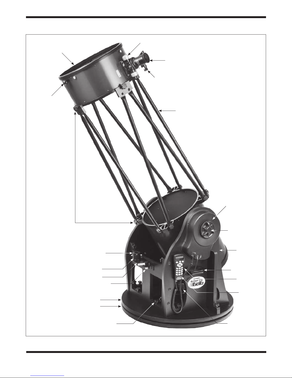
Upper optical
tube section
Navigation
knob
2" Dual-speed
Crayford focuser
2" DeepView eyepiece
EZ Finder II
Truss poles
Captive
clamping
knobs (x12)
1.25" eyepiece adapter
2" extension adapter
Eyepiece rack
12.5mm Illuminated Plössl
Top groundplate
Bottom groundplate
Captive base
connecting bolts (x12)
Figure 1. Overview of SkyQuest XXg Dobsonian (16" shown)
Altitude motor and
encoder housing
Altitude
clutch knob
Lower optical
tube section
Handle
Hand controller
bracket
GoTo hand
controller
Azimuth motor and
encoder housing
2

Congratulations on your purchase of an Orion SkyQuest XXg GoTo Dobsonian. These revolutionary Dobs
combine large-aperture optical performance with state-of-the-art computerized GoTo pointing capability. Moreover, these big telescopes were designed by Orion to be remarkably transportable – both their
base and optical tube break down into easily manageable components that can fit into any standard size
vehicle. Setup for an observing session takes just minutes, and the views are spectacular! We know you
will enjoy many years of rewarding observations with your SkyQuest XXg GoTo Truss Dobsonian.
Please read these instructions thoroughly before beginning assembly and subsequent use of the telescope.
1. Unpacking
Table of Contents
1. Unpacking . . . . . . . . . . . . . . . . . . . . . . . . . . . . . . 3
2. Assembly . . . . . . . . . . . . . . . . . . . . . . . . . . . . . . . 7
3. The GoTo Hand Controller . . . . . . . . . . . . . . . . . 15
4. Collimating the Optical System . . . . . . . . . . . . . 16
5. Using Your Telescope . . . . . . . . . . . . . . . . . . . . . 18
6. Specifications. . . . . . . . . . . . . . . . . . . . . . . . . . . 22
WARNING: Never look directly at the Sun through your
telescope or its finder scope – even for an instant – without a professionally made solar filter that completely covers the front of the instrument, or permanent eye damage
could result. Young children should use this telescope
only with adult supervision.
The SkyQuest XX12g is packed in three boxes, one containing the optical tube assembly (OTA), truss poles, and accessories; a second containing the unassembled Dobsonian
base; and third containing the primary mirror and mirror cell.
The XX14g ships in four boxes, with the truss poles and counterweights contained in a separate box. The XX16g is packaged in five boxes, with the base components divided into two
separate boxes to keep the weight and size of the individual
boxes more manageable.
Before beginning assembly, unpack each box and confirm
that all of the parts in the Parts List below are present. The
parts are listed by the box they should arrive in, but some of
the parts may be in different boxes than indicated below. Be
sure to check all boxes carefully, as some parts are small. If
anything appears to be missing or broken, immediately call
Orion Customer Support (800-676-1343) or email support@
telescope.com for assistance.
3
Parts List
Box #1: Optical Tube Assembly and Accessories
(Figure 2)
Qty. Description
1 Lower optical tube section
1 Upper optical tube section
2 Optical tube dust covers (one for each tube section)
4 Truss pole pairs (XX12g only)
1 DeepView 28mm eyepiece, 2"
1 Eyepiece extension adapter, 2" (not shown)
1 Illuminated 12.5mm Plössl eyepiece, 1.25"
1 EZ Finder (with bracket)
1 Collimation cap
1 Eyepiece rack
2 Eyepiece rack wood screws (20mm long, color black)
2 Hex keys (2mm, 2.5mm)
1 Tube connecting knob
1 SynScan AZ Hand controller
1 Hand controller cable (coiled)
1 Azimuth motor connection cable
1 RS-232 computer interface cable
1 Hand controller bracket (with 2 mounting screws)
3 Counterweight mounting bolts (XX14g, XX16g)
1 Cooling accelerator fan with battery holder
(XX12g only)
1 Instruction manual (not shown)
1 Starry Night CD-ROM
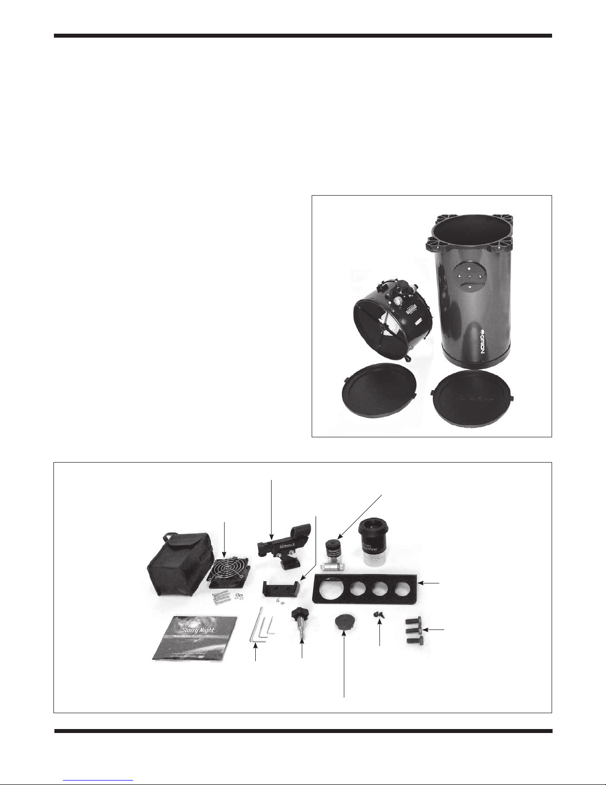
Lower
optical tube
section
Upper
optical tube
section
a.
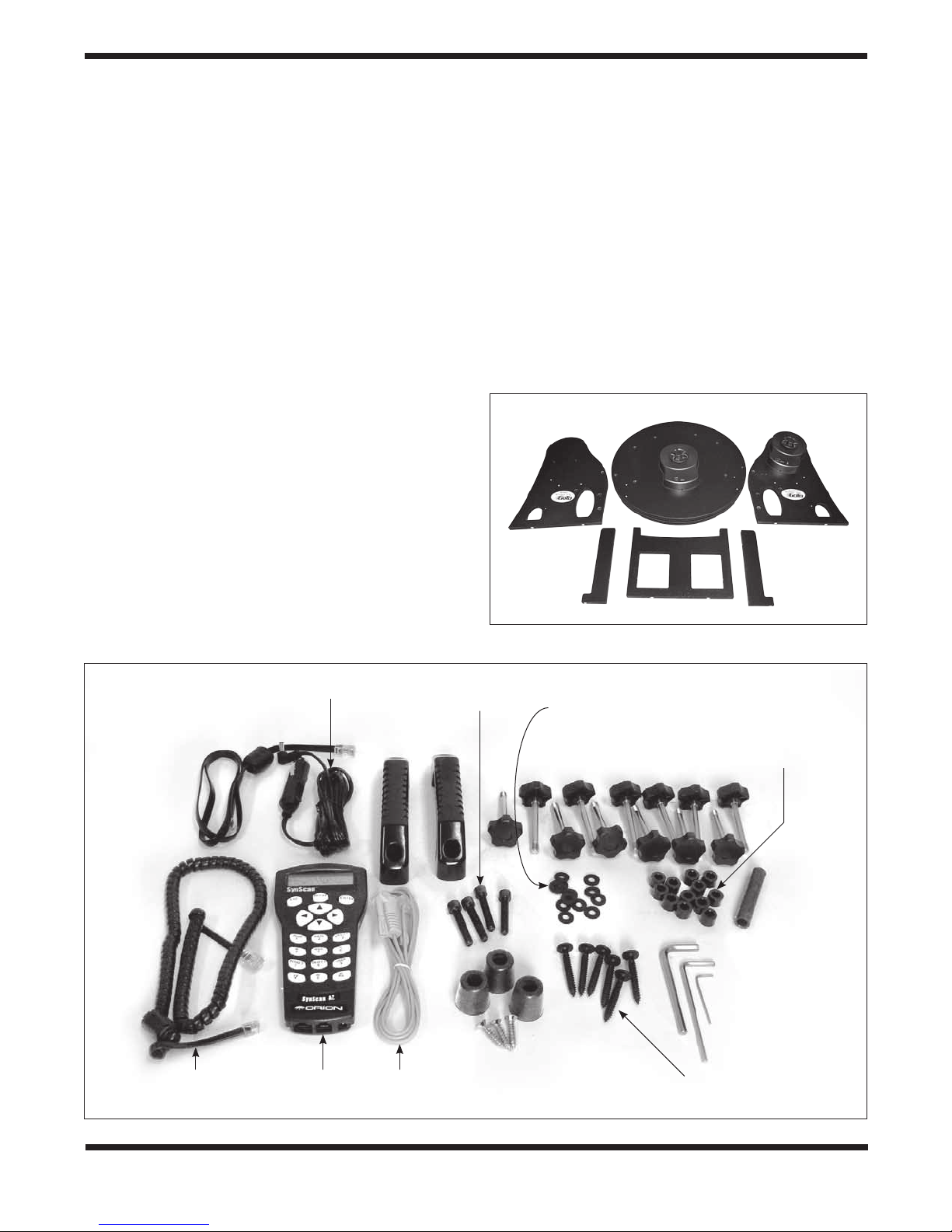
Figure 2. Contents of the optical tube box. a) The larger
components. b) Accessories and hardware.
b.
Cooling fan and
mounting screws
(XX12g only)
Battery pack
(XX12g only)
Starry Night
Special Edition
CD-ROM
EZ Finder II
Hex keys
Bracket for hand
controller and
mounting screws
Tube
connecting
bolt
Quick collimation cap
Dust covers
12.5mm Illuminated
Plössl eyepiece
with illuminator arm
DeepView 28mm
2" eyepiece
Eyepiece
rack
mounting
screws
Eyepiece rack
Counterweight
mounting bolts
(XX14g and
XX16g only)
4
Box #2: Primary Mirror and Cell (Figure 3)
Qty. Description
1 Parabolic primary mirror (XX12g, flat back; XX14g and
XX16g, convex back)
1 Mirror support cell
3 Collimation knobs
3 Nylon washers (3/4" outer diameter)
3 Springs
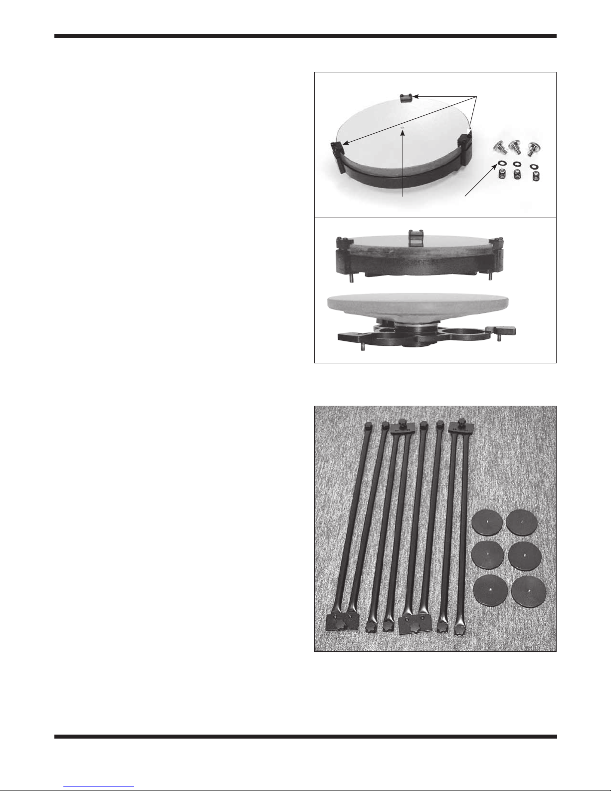
Box #3: Truss Pole Assemblies and
Counterweights (XX14g and XX16g) (Figure 4)
Qty. Description
4 Truss pole pairs
6 Counterweights, 2.2 lbs. each (XXX14g only)
9 Counterweights, 2.2 lbs. each (XXX16g only)
Primary mirror in
mirror support cell
(XX12g)
a.
b.
Mirror
retaining
clips
Collimation
knobs
Springs
WashersCenter mark
XX12g
XX14g
and
XX16g
Figure 3. Contents of the primary mirror box. a) The primary
mirror, mirror cell, and collimation hardware for the XX12g. b) The
primary mirrors and mirror support cells for the XX12g (top) and
XX14g/XX16g are quite different.
Figure 4. Contents of the truss pole and counterweight box.
(The XX16g contains nine counterweights.) For the XX12g, the
truss poles are included in the optical tube box, and there are no
counterweights.
5
Box #4: Dobsonian Base (Figure 5)
Qty. Description
1 Left side panel (with altitude motor and encoders pre-
installed)
1 Right side panel
1 Front panel
2 Side braces
1 Groundplate assembly (with azimuth motor and
encoders pre-installed) This is contained in a separate
box (Box #5) for the XX16g.
6 Base assembly wood screws (coarse thread, 47mm
long)
12 Base connecting bolts with hand knobs
12 Rubber retaining washers
12 Spacers for connecting bolts
1 Insertion tube for rubber retaining washers (~3" long)
2 Carrying handles
4 Handle mounting bolts (socket head cap screws,
25mm long)
3 Hex keys (size 2mm, 4mm, 6mm)
3 Plastic feet (XX12g only; feet are pre-installed on
XX14g and XX16g)
3 Feet wood screws (1" long; XX12g only)
Box #5: Dobsonian Base (XX16g only)
Qty. Description
1 Groundplate assembly (with azimuth motor and
encoders pre-installed)
Right side panel
Groundplate assembly
Left side panel
b.
Azimuth motor
connection cable
DC power cable
Handles
a.
Figure 5. Contents of the base box(es). a) The larger components,
b) Hand controller, cables, and other hardware.
Mounting bolts
for handles
Side brace Side brace
Front panel
Rubber retaining
washers
Base connecting
bolts (x12)
Spacers for
connecting
bolts (x12)
Insertion tube
Hex keys
Coil cable for
hand controller
Hand
controller
6
RS-232
cable
Feet (x3) and mounting screws
(Feet come pre-installed on
XX14g and XX16g)
Base assembly
wood screws (x6)
2. Assembly
Now that you have unpacked the boxes and familiarized yourself with all the parts, it is time to begin assembly.
Initial Assembly of the GoTo Dobsonian Base
The GoTo bases of the SkyQuest XXg Dobs are shipped partially assembled for your convenience. All the motors, optical
encoders, and gears are pre-installed at the factory. The two
round groundplates are preassembled and should not be
taken apart.
When fully assembled, the SkyQuest XXg GoTo Truss Tube
Dobsonians are big telescopes. But we designed them to
break down into easily manageable components, none of
which is too big or too heavy for a reasonably fit individual
to lift and carry (but for the XX16g a helper would be great!).
In fact, both the base and the optical tube can be quickly
disassembled into smaller components for transport and/
or storage, then reassembled – all without tools! We’ll get
to the tube later, but for the base you’ll see that it has four
main components: the groundplate assembly (top and bottom
groundplates and installed azimuth motor housing), the left
side panel with installed altitude motor housing, the right side
panel, and the front panel.
For the initial assembly of the base, you will need a Philips
screwdriver.
1. To install the feet (XX12g only; feet are pre-installed at
the factory on the XX14g and XX16g), turn the groundplate assembly upside-down and gently rest it on the azimuth motor housing on a clean, flat surface. Carpet is
good, or you may want to place a cloth under the azimuth
motor housing to avoid scratching it. Locate the three
starter holes on the perimeter of the bottom groundplate (Figure 6a). Insert the screws through the feet and
thread them into the predrilled starter holes (Figure 6b)
with a Phillips screwdriver until tight.
2. Connect the side braces to the side panels using three
base assembly screws for each panel (Figure 7). The
brace should be attached to the outside surface of the
side panel – the outside of the left side panel has the
altitude motor housing attached. The screws go through
the holes in the side panels and thread into the starter
holes in the side braces. Use the included 4mm hex key
to firmly tighten the screws, but be careful not to strip the
holes by over-tightening!
3. Now you will install the captive connecting bolts, each of
which is already fitted with a black hand knob. There are
12 connecting bolts altogether; refer to Figure 8 for locations. Start with the front panel, which has through holes
for six connecting bolts.
First, slide a spacer onto a collecting bolt. Then insert
the connecting bolt into the through hole, in the direction
indicated in Figure 8. Holding the knob with one hand,
use your other hand to press a rubber washer over the
threaded (protruding) end of the bolt. It will be a tight fit;
you may have to work the washer a bit to get it on. Push
the washer up on the bolt as far as you can with your
a.
b.
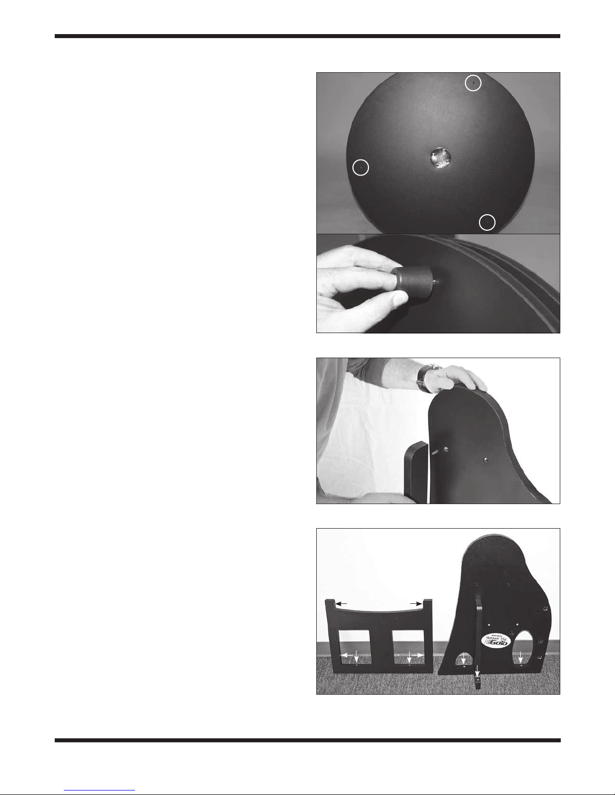
Figure 6. a) Starter holes for feet on bottom baseplate.
b) Attaching the base feet.
Side
panel
Side
brace
Figure 7. Attach a side brace to the outside of each side panel
using three base assembly wood screws and the 4mm hex key.
Figure 8. Locations for connecting bolts in the front and side panels
(one side panel not shown). Connecting bolts should be inserted in
the predrilled holes in the direction indicated by the arrows.
7
a.
Rubber
washer
Spacer (Don’t
forget this!)
b.
Insertion
tube
Figure 10. The completed side panel and front panel assembly.
Keyholes
c.
Figure 11. Place the large opening of the “keyhole” slots in the
eyepiece rack over the mounting screw heads, then push the rack
downward. To do this, leave the screw heads about 1/8" out from
the panel. After the rack is installed, you can tighten the screws to
secure it in place.
Hand controller
bracket
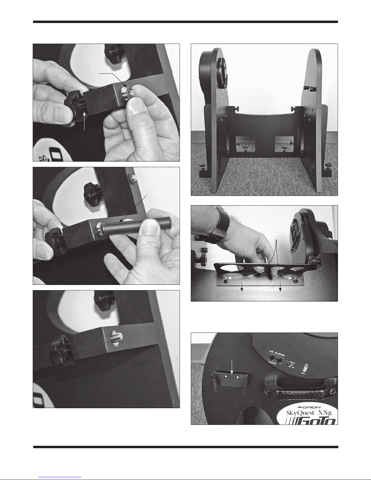
Figure 9. a) Place a rubber washer on the threaded end of the
connecting bolt and push it on as far as you can with your fingers.
b) Then use the included insertion tube to push the washer past
the threads and up into the counterbored hole in the wood. c) The
recessed washer will keep the bolt captive in the hole.
8
Figure 12. Find the two pilot holes and attach the hand controller
bracket – but don’t overtighten the screws!

Figure 13. The altitude motor housing has jacks for the hand
controller (HC) cable, azimuth motor connection cable, and power
cable as well as an ON/OFF switch.
fingers (Figure 9a). Then place the insertion tube on the
bolt (Figure 9b) and use it to push the washer farther
up on the bolt, into the counterbored hole in the wood
(Figure 9c). The washer will keep the bolt captive when
it is fully disengaged from the mating part of the base.
Repeat this procedure for the other five connecting bolts
to be installed in the front panel, and for the six additional connecting bolts that attach the side panels and side
braces to the top groundplate.
4. Now attach the front brace to the two side panels with the
four appropriate captive connecting bolts. Use the hand
knob to screw each bolt into the threaded metal receptacle recessed in the side panel. The side panels should
be oriented so the side braces are facing outward. The
front panel should be oriented so that the two pilot holes
for the eyepiece rack face outward. Do not completely
tighten the connecting bolts yet. The completed assembly should look like Figure 10.
5. Place the assembled side panel/front panel structure on
the top groundplate, aligning the protruding connecting
bolts with the threaded inserts in the groundplate. Turn
the connecting bolt hand knobs to fasten the side panel/
front panel structure to the groundplate. Firmly tighten all
12 connecting bolts installed in steps 3 and 4. To avoid
stripping the threads, do not overtighten.
6. Attach a handle on each of the two side panels. Insert
a large socket head cap screw through the holes in the
handle and into the predrilled hole in the side panel. The
hole has a flanged threaded metal insert in it. Use the
6mm hex key to thread the screw into the insert until tight.
Refer to Figure 1 for handle placement.
7. The aluminum eyepiece rack holds three 1.25" eyepieces
and one 2" eyepiece in a convenient place on the base,
within easy reach while you are observing. To attach the
eyepiece rack, locate the two small pilot holes on the
front panel. Thread the small Phillips-head screws into
the holes until the screw head is about 1/8" from the
panel’s surface. Now place the wide part of the “keyhole”
on the eyepiece rack over the screw heads and slide it
downward until it stops (Figure 11). Tighten the screws
to secure the rack in place.
8. The XXg base includes a bracket that holds the hand
controller when it’s not in use. The bracket mounts on
the left side panel adjacent to the altitude motor housing
(Figure 12). Locate the two small pilot holes and attach
the bracket using the small screws included with the
bracket until just barely tight. Do not over-tighten these
screws or you will strip the holes!
9. Now install the azimuth motor connection cable. It is a
flat cable that has an 8-pin RJ-45 plug on both ends.
Plug one end into the jack on the azimuth motor housing on the top groundplate; plug the other end into the
jack labeled AZ MOTOR on the altitude motor housing
(Figure 13).
10. Finally, connect the GoTo hand controller. Plug the wide
RJ-45 connector on the coiled hand controller cable into
the corresponding port on the hand controller. Plug the
smaller RJ-12 connector into the port labeled HC on the
altitude motor housing. Refer to the SynScan GoTo Hand
Controller manual.
Initial Assembly of the Optical Tube
The primary mirror is shipped in its metal support cell separately from the optical tube, to prevent possible damage to
both the mirror and the optical tube. Once the primary mirror
is installed, there will be no need to remove it except if cleaning is necessary (see “Care & Maintenance”). First, the mirror
will be installed in the lower tube section, then the truss poles
and upper tube section will be attached.
The primary mirror of the XX12g has the typical flat back side,
whereas the thinner primaries of the XX14g and XX16g have
a “conical,” or convex back with raised “ribs” radiating from the
center for added strength. The reduced-mass design of these
larger mirrors allows more-efficient equilibration to outdoor
ambient temperature. All the primary mirrors have a small
adhesive ring placed in the exact center (Figure 3a); it aids
in achieving a precise collimation, which will be covered later.
The ring, which has no effect on the image rendered by the
telescope, should NOT be removed.
9

Figure 14. To remove the rear end ring, unthread the screws that
connect it to the tube.
Figure 15. Thread the three hex-head counterweight mounting
bolts (XX14g and XX16g only) into the holes in the counterweight
support plates as shown. Tighten using an adjustable or 16mm
crescent wrench.
1. To install the mirror cell in the optical tube, the rear end
ring attached to the lower tube section must first be
removed. This is done by unthreading and removing the
Phillips-head screws that attach the end ring to the tube
(Figure 14), and then pulling the end ring off of the tube.
Warning: Once the rear end ring is removed from
the tube, the raw edge of the tube itself will be
exposed. Be careful not to cut or otherwise hurt
yourself on the tube’s edge. Also, be careful not
to pinch your fingers between cell and tube when
re-attaching the assembled mirror cell!
2. Next, for the XX14g and XX16g, thread the three counterweight mounting bolts into their respective holes in the
rear end ring, as shown in Figure 15. Use an adjustable
wrench or a 16mm crescent wrench to tighten the bolts.
Do not install the counterweights yet.
3. Next, assemble the telescope’s rear end ring to the primary mirror cell. Find a clean, flat surface, and turn the
mirror cell over so that the mirror is facing downward.
For the XX14g and XX16g, we recommend placing a
soft towel on a flat surface and placing the mirror face
down on the towel, because the aluminized outer edge
of the mirror will contact the surface. With the XX12g mirror on the other hand, the aluminized mirror itself will not
Spring
a.
b.
Collimation
knob
c.
Figure 16. Shown for XX12g. a) Place the three springs on the
exposed threaded shafts of the mirror cell. b) Lower the rear end
ring onto the mirror cell so that the threaded shafts pass through
the end ring, and the end ring rests on the springs. c) Thread the
collimation knobs, with nylon washers attached, through the rear end
ring and onto the threaded shafts. Make sure the knobs have at least
three full turns of engagement on the shafts.
Figure 17. Locate the area of tube that is bulging out and
preventing the end ring from fully seating. Press on this bulge to
allow the mirror cell to seat properly on the tube. Be careful not to
pinch fingers!
Shaft
Nylon
washer
10
a.
Altitude axis
trunnion
b.
a.
Altitude side
bearing (dovetail)
Altitude
clutch knob
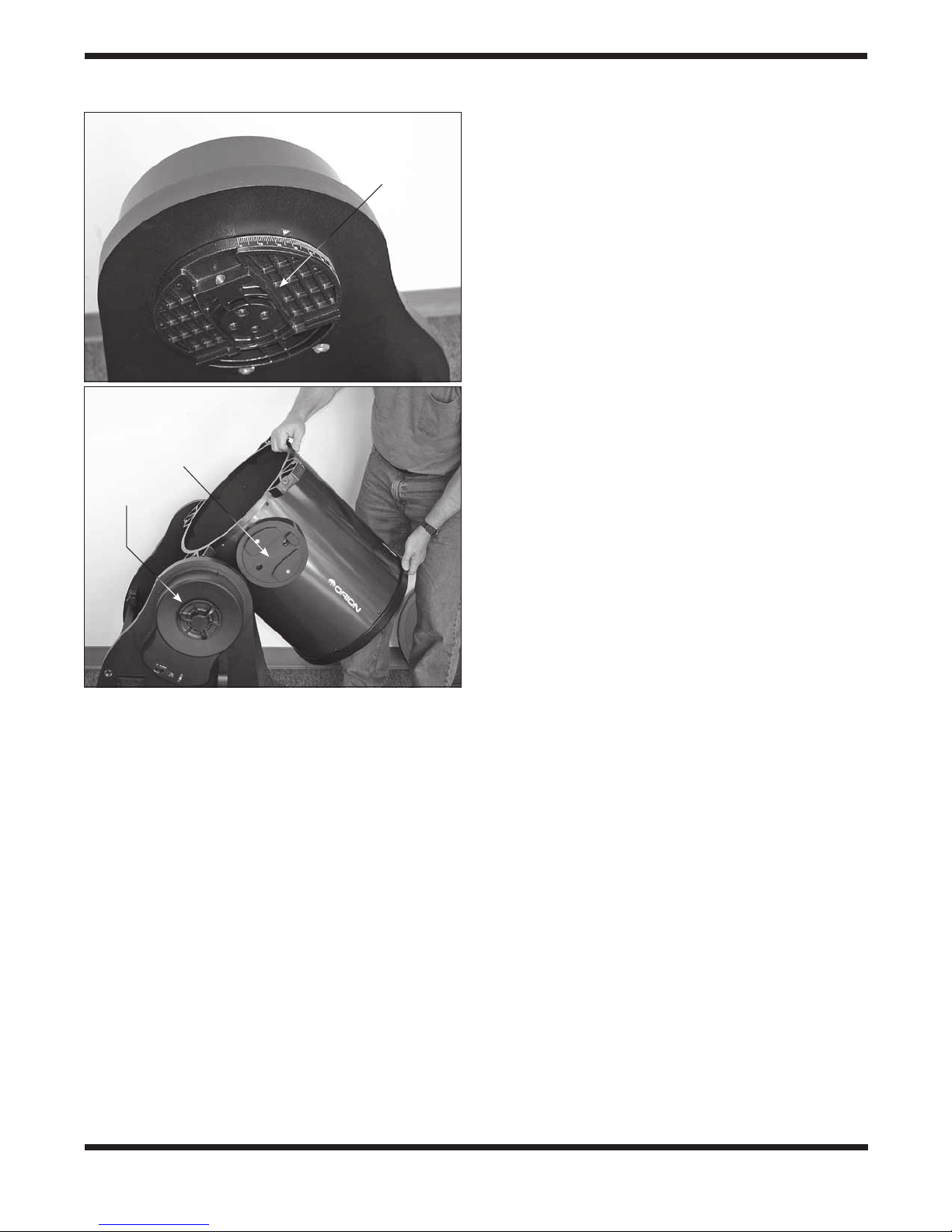
Figure 18. a) Altitude axis trunnion on left side panel. b) Grasp
both ends of the lower tube section to lift it, then lower it into the
base, sliding the dovetail slot in the tube’s left altitude bearing into
the mating part of the trunnion.
make contact with the surface; only the mirror retaining
clips will. Place the three springs onto the three exposed
threaded shafts (Figure 16a). (The XX12g mirror is
shown, but the procedure is similar for the XX14g and
XX16g.) Lower the end ring onto the mirror cell so the
threaded shafts pass through it, and the end ring rests on
the springs (16b). Add a nylon washer to each collimation knob and thread the collimation knobs through the
end ring and onto the threaded shafts (16c). Make sure
the knobs have at least three full turns of engagement
on the shafts. The mirror cell is now almost ready to be
installed onto the lower tube section.
4. Check to make sure that the three mirror retaining clips
are properly tensioned (XX12g only, Figure 3a). If they
are too tight, the pinching of the mirror’s edge will distort the images you see through the telescope. But if they
are too loose, the mirror could shift or even fall out if it is
tilted severely. With the mirror in its cell facing up, use a
Phillips screwdriver to loosen the two screws on one of
the clips until you can easily move the small metal plate
underneath the screw heads. Then gradually tighten both
screws just until the metal plate is no longer loose – no
tighter! Repeat this with the other two retaining clips. Now
the clips are properly tensioned.
5. Assembling the end ring (and mirror assembly) back onto
the tube can be a bit tricky. This is because the large
diameter and thin metal of the tube will cause the tube
to become somewhat out of round once the end ring is
removed. To assemble the rear end ring (with mirror and
mirror cell now connected) to the tube, stand the lower
section of the tube up vertically so the raw edge of the
tube is up. Line up the threaded holes in the edge of the
end ring with the holes in the end of the tube. Then, lower
the entire assembly onto the tube. (Be careful to avoid
finger pinching during this step!) There may be a bulge in
the perimeter of the tube that prevents the end ring from
fully seating onto the tube (Figure 17). Press against this
bulge, and the entire mirror cell assembly should seat
onto the tube. Now, replace the Phillips screws that fasten the rear end ring to the tube.
Before assembling the rest of the optical tube, you should consider how you want to mount the optical tube on the base. We
recommend mounting the lower tube section onto the base
first, THEN adding the counterweights, then the truss poles
and upper tube section. Alternatively, you could complete the
assembly of the entire optical tube first, then hoist the whole
thing onto the base. But for that we strongly recommend getting a second person to help with the lifting – at least for the
XX14g and XX16g. For these instructions, we will outline the
procedure for installing the lower tube section on the mount
first, then building the rest of the OTA from there.
Mounting the Lower Tube Section (Only) on
the Base
1. Loosen the altitude clutch knob slightly so the altitude
trunnion can rotate with relatively little resistance.
Note: To keep the bottom tube section as light as
possible for lifting during installation, do not install
the counterweights until after the tube is installed
on the base (see step 4 below).
2. The left altitude side bearing on the optical tube has a
dovetail slot that slides onto the altitude axis trunnion on
the inside of the left side panel (Figure 18a). We recommend orienting the trunnion such that the threaded
hole for the tube connecting knob is at about a 45-degree
angle from horizontal. If the altitude trunnion is oriented
differently, you’ll have to adjust the angle of the telescope
tube accordingly to mount it. Grasp the tube section as
shown in Figure 18b and lift it. Slide the tube’s dovetail
altitude bearing into the mating receptacle of the altitude
trunnion on the base. Once seated in the base, the tube
will freely rotate to a vertical position due to its bottomheavy imbalance. Maintain your grip on the tube and
gently guide it to the resting, vertical position.
11

Altitude
motor/encoder
housing
Tube
connecting
knob
Figure 19. Secure the tube to the base with the tube connecting
knob.
3. Now insert and tighten the tube connecting knob to
secure the tube in place (Figure 19).
4. For the XX14g and XX16g, before assembling the rest
of the optical tube, it is recommended that you install the
counterweights on the rear cell so that the tube, when
assembled, will be properly balanced rather than frontheavy. (The XX12g does not utilize counterweights.)
Without counterweights, the fully assembled tube could
swing forward rapidly, possibly damaging the tube and
mirrors.
There are six counterweight disks for the XX14g and nine
for the XX16g, each weighing 2.2 lbs. For the XX14g, two
counterweights are to be threaded onto each bolt, while
for the XX16g three counterweights should be installed on
each bolt (Figure 20). Tilt the lower tube section as needed to access the counterweight mounting bolts on the rear
cell, and thread the counterweights onto each of the three
mounting bolts. Spin them clockwise until they stop.
5. Now, attach the four truss pole assemblies to the lower
tube section. Connect the eight captive clamping knobs
on the ends of the pole assemblies to the lower truss sup-
Counterweight
Counterweight
mounting bolts
Figure 20. Installing counterweights (XX14g and XX16g only).
Thread two (for XX14g) or three (for XX16g) 2.2-lb. counterweights
onto each counterweight mounting bolt for proper tube balance.
Truss pole
assembly
Clamping
knobs
12
Lower
truss
Lower tube
section
Figure 21 The clamping knobs on the ends of the truss pole
assemblies thread into the holes in the lower truss support ring on
the lower tube section.
Focuser
support
ring

Focuser
Left side
bearing
Figure 22. The upper tube section should be oriented relative to
the lower tube section as shown. Note the orientation of the focuser
on the upper tube section relative to the side bearing on the lower
tube section.
port ring on the lower optical tube section (Figure 21).
This is done by simply threading the knobs into the holes
in the support ring. Do not completely tighten the knobs
just yet.
6. Attach the upper tube section to the four truss connectors at the top of the poles. Orient the upper tube section
as shown in Figure 22. Hold the upper tube section with
one hand while threading the knobs in the truss connectors into the holes in the upper truss support ring. If necessary, you can slightly adjust the position of the truss
connector with respect to the pole ends in order to have
Truss
connector
Truss
poles
a. b.
Figure 23. The position of the truss connectors relative to the pole
ends can be adjusted to register the truss connectors with the upper
truss support ring.
Registration
flats
Upper truss
support ring
Figure 24. When the truss clamping knob is tightened, it will clamp
the truss connector against the registration flats on the upper truss
support ring.
Button head cap screw
Truss connector knob
Truss
connector
the knobs and holes line up (Figure 23). When tightened,
the knob will clamp the truss connector against the registration flats on the upper truss support ring (Figure 24).
Repeat this for the other three truss connectors. Firmly
tighten the knobs.
7. Now go back and firmly tighten the eight clamping knobs
on the lower truss support ring.
If, after assembling, the truss poles are loose within the truss
connectors, use the supplied 4mm hex key to tighten the button head cap screws that connect the poles to the truss connectors (see Figure 23). This should rarely need to be done.
The telescope is now assembled.
13

Accessory Installation
Now that the base is assembled and the optical tube assembled and mounted, all that remains is to attach the EZ Finder
II reflex sight and pop an eyepiece into the focuser.
EZ Finder II
Using the included dovetail mounting bracket, the EZ Finder II
will slip neatly into the dovetail base pre-installed on the upper
tube section adjacent to the focuser. Just slide the dovetail
mounting bracket into the telescope’s dovetail mounting base
and tighten the thumbscrew on the base to secure the mounting bracket. Make sure the sight tube of the EZ Finder II is
forward (closest to front opening of telescope).
Operating the EZ Finder II
Before installing the EZ Finder II on the telescope, you’ll need
to insert the included 3-volt lithium battery.
1. Insert a small, flat-blade screwdriver into the notch in the
battery casing and gently pry it off (Figure 26).
2. Slide the CR2032 3V lithium battery under the retaining
clip with the positive (+) side facing down (touching the
clip).
3. Then press the battery casing back on.
Should the battery die, replacement CR2032 batteries are
available at many stores where small batteries are sold.
The EZ Finder II works by projecting a tiny red dot (it is not
a laser beam) onto a lens mounted in the front of the unit.
When you look through the EZ Finder II, the red dot will
appear to float in space, helping you to pinpoint your target
object (Figure 25). The red dot is produced by a light-emitting
diode (LED) near the rear of the sight. Turn the power knob
(see Figure 26) clockwise until you hear the “click” indicating
that power has been turned on. Look through the back of the
reflex sight with both eyes open to see the red dot. Position
your eye at a comfortable distance from the back of the sight.
In daylight you may need to cover the front of the sight with
your hand to be able to see the dot, which is purposefully
quite dim. The intensity of the dot is adjusted by turning the
power knob. For best results when stargazing, use the dimmest possible setting that allows you to see the dot without
difficulty. Typically a dimmer setting is used under dark skies
and a brighter setting is needed under light-polluted skies or
in daylight.
Figure 25. The EZ Finder II superimposes a tiny red dot on the
sky, showing right where the telescope is aimed.
Power knob
Altitude
adjustment
knob
Figure 26. The EZ Finder II reflex sight.
Thumbscrews
Sight
tube
Azimuth
adjustment
knob
Battery
casing
Dovetail
mounting
bracket
and altitude (up/down) adjustment knobs (see Figure 26)
to position the red dot on the object in the eyepiece. When
the red dot is centered on the distant object, check to make
sure that the object is still centered in the telescope’s field of
view. If not, re-center it and adjust the EZ Finder II’s alignment
again. When the object is centered in the eyepiece and on
the EZ Finder’s red dot, the EZ Finder II is properly aligned
with the telescope. Once aligned, the EZ Finder II will usually
hold its alignment even after being removed and remounted.
Otherwise, only minimal realignment will be needed. At the
end of your observing session, be sure to turn the power knob
to the Off position.
Aligning the EZ Finder II
When the EZ Finder II is properly aligned with the telescope,
an object that is centered on the EZ Finder II’s red dot should
also appear in the center of the field of view of the telescope’s
eyepiece. Alignment of the EZ Finder II is easiest during daylight, before observing at night. Aim the telescope at a distant
object such as a telephone pole or roof chimney and center it
in the telescope’s eyepiece. The object should be at least 1/4
mile away. Now, with the EZ Finder II turned on, look though it.
The object should appear in the field of view. Without moving
the main telescope, use the EZ Finder II’s azimuth (left/right)
14
Using Eyepieces
The final step in the assembly process is to insert an eyepiece into the telescope’s focuser. First, take the cover cap
off the focuser drawtube. To use the 2" DeepView eyepiece,
loosen the two thumbscrews on the 2" accessory collar (on
the end of the focuser drawtube) and remove the 1.25" adapter. Then place the 2" eyepiece directly into the 2" accessory
collar and secure it with the two thumbscrews loosened previously (Figure 27). If you cannot achieve focus, you may need
to install the included 2" extension adapter on the focuser,
then insert the eyepiece into it. The other eyepiece and 1.25"
1.25" adapter
thumbscrew
2" collar
thumbscrews
Coarse
focus
knob
Figure 27. Detail of the dual-speed focuser.
Focuser cap
Drawtube tension setscrew
1.25" adapter
2" accessory collar
Fine
focus
knob
Coarse
focus knob
Focus lock
thumbscrew
adapter can be placed in the eyepiece rack until they are
needed.
To install the 1.25" Illuminated Plössl eyepiece instead of the
2" DeepView eyepiece, keep the 1.25" adapter in the focuser,
and make sure the two thumbscrews on the 2" collar are tightened. Now, loosen the thumbscrew on the 1.25" adapter, do
not loosen the two thumbscrews on the 2" collar. Insert the
1.25" eyepiece into the 1.25" eyepiece adapter, and secure it
by retightening the thumbscrew on the 1.25" eyepiece adapter (Figure 27). The other eyepiece can be placed in the eye-
piece rack until it is needed.
The basic assembly of your SkyQuest XXg Dobsonian is now
complete. It should appear as shown in Figure 1. Keep the
dust cap in place on the bottom tube section when the telescope is not in use, to minimize the accumulation of dust on
the primary mirror. It is also a good idea to store eyepieces in
an eyepiece case and to replace the cover cap on the focuser
when the telescope is idle.
Tips for Transporting Your XXg
The SkyQuest XXg Dobsonians are big scopes, but they were
designed with portability in mind. For all three telescopes, the
optical tube and the GoTo base break down without tools into
manageable components for transporting to and from your
favorite observing site in a standard-sized vehicle, or for more
convenient storage in your home or garage.
A fit individual should have no trouble setting up, dismantling,
or carrying the individual components of an XXg Dobsonian
short distances without assistance. Of course, having a helper will facilitate these activities, but if or when you find yourself
on your own for an evening observing session, you should
be just fine! The larger XX16g could be more of a challenge
for one person, especially if you are of slight build. Its heaviest component, the groundplate assembly, weighs 61 lbs.,
so keep that in mind. The good news is that the groundplate
assembly can be rolled on its edge like a big wheel! But lifting
it to get it into and out of a car requires some muscle if you’re
doing it by yourself. With a helper, however, it should be no
problem.
For the XX16g, an optional transport solution is available
that allows the telescope to be rolled while fully assembled.
Featuring 10" pneumatic tires, this transport solution is particularly useful for moving the telescope from, say, a garage
out onto the driveway or into the backyard observing spot. It
obviates the need to disassemble the telescope just to move
it a short distance! Visit OrionTelescopes.com or call Orion
customer service at 800-676-1343 for details.
The optical tube disassembles into a small front tube section
including the secondary mirror and focuser, rear tube section housing the primary mirror cell, and four truss-pole pairs.
We recommend dismantling the optical tube in reverse order
from the way it was assembled. That is, remove the upper
tube section first, then the truss tube assemblies, then the
counterweights, and finally, remove the lower tube section
from the base.
The base disassembles into four separate components: the
groundplate assembly (top and bottom groundplates with azimuth motor and encoders installed), left side panel (with altitude motor and encoders installed), right side panel, and front
panel. All the hardware has hand knobs for tool-free manipulation and is captive so that nothing will drop off and get dirty
or lost in the dark.
Before transporting the telescope, remove the EZ Finder II
(with bracket) and any eyepiece from the focuser. The eyepiece rack can also be removed from the base, if you wish.
This will prevent these accessories from getting damaged
during transport. These items can be placed in an optional
accessory case.
If possible, transport the bottom tube section containing the
primary mirror in an upright position, i.e., with the rear end ring
resting on the ground. Doing so will reduce stress on the mirror
support system. We recommend transporting the tube assembly in the optional padded case set for proper protection.
Each time you assemble the optical tube for an observing
session, you should check the optical collimation. It may not
need any adjustment, but it could require a minor tweak to
dial it in precisely. See the section on collimation for details on
how to collimate the optics.
3. The GoTo
Hand Controller
SkyQuest XXg telescopes feature the SynScan hand controller, which contains an extensive database of stars, deep-sky
objects, and solar system denizens – nearly 43,000 in all. The
features and functionality of the SynScan controller are covered in detail in a separate manual entitled SynScan GoTo
Hand Controller. Please refer to that manual before beginning
your explorations with the SkyQuest XXg.
15

Primary mirror
center mark
(XX12g
only)
b.
c.
a.
d.
Figure 28. Collimating the optics. (a) When the mirrors are properly aligned, the view down the focuser drawtube should look like this. (b)
With the collimation cap in place, if the optics are out of alignment, the view might look something like this. (c) Here, the secondary mirror is
centered under the focuser, but it needs to be adjusted (tilted) so that the entire primary mirror is visible. (d) The secondary mirror is correctly
aligned, but the primary mirror still needs adjustment. When the primary mirror is correctly aligned, the “dot” will be centered, as in (e).
e.
4. Collimating the
Optical System
To get the sharpest images, your telescope’s optical system must be in precise alignment. The process of aligning
the primary and secondary mirrors with each other and with
the mechanical axis of the telescope is called collimating.
Collimating is relatively easy to do and can be done in daylight or at night.
Because the primary mirror is shipped separately from the
optical tube, the telescope’s optics must be collimated before
it can be used. Most of the adjustments will be to the tilt of the
primary mirror, as the secondary mirror has been pre-aligned
at the factory. It is also good idea to check the collimation
(optical alignment) of your telescope before each observing
session and make any necessary adjustments.
To check collimation, remove the eyepiece and look down the
focuser drawtube. You should see the secondary mirror centered in the drawtube, as well as the reflection of the primary
mirror centered in the secondary mirror, and the reflection of
the secondary mirror (and your eye) centered in the reflection
of the primary mirror, as depicted in Figure 28a. If anything
is off-center, as in Figure 28b, proceed with the following collimation procedure.
The Collimation Cap and Mirror Center Mark
Your XXg comes with a collimation cap. This is a simple cap
that fits on the focuser drawtube like a dust cap, but has a
hole in the center and a reflective inner surface. The cap
helps center your eye so that collimating is easier to perform.
Figures 28b-e assume you have the collimation cap in place.
As an additional aid in collimating, the primary mirror of
the XXg has a tiny adhesive ring marking its exact center
(Figure 3a). This center ring will not affect the images you
see when observing with the telescope in any way (since
it lies directly in the shadow of the secondary mirror), but it
will greatly facilitate collimating when using the supplied collimation cap or other, more sophisticated collimation devices,
such as the Orion LaserMate Deluxe II laser collimator.
Preparing the Telescope for Collimating
Once you get the hang of collimating, you will be able to do it
quickly even in the dark. For now, it is best to collimate in daylight, preferably in a brightly lit room and aimed at a white wall.
It is recommended that the telescope tube be oriented horizontally. This will prevent any parts from the secondary mirror
from falling down onto the primary mirror and causing damage if something comes loose when you are making adjustments. Place a sheet of white paper inside the optical tube
directly opposite the focuser. This will provide a bright “background” when viewing into the focuser. When properly set up
for collimation, your telescope should resemble Figure 29.
16
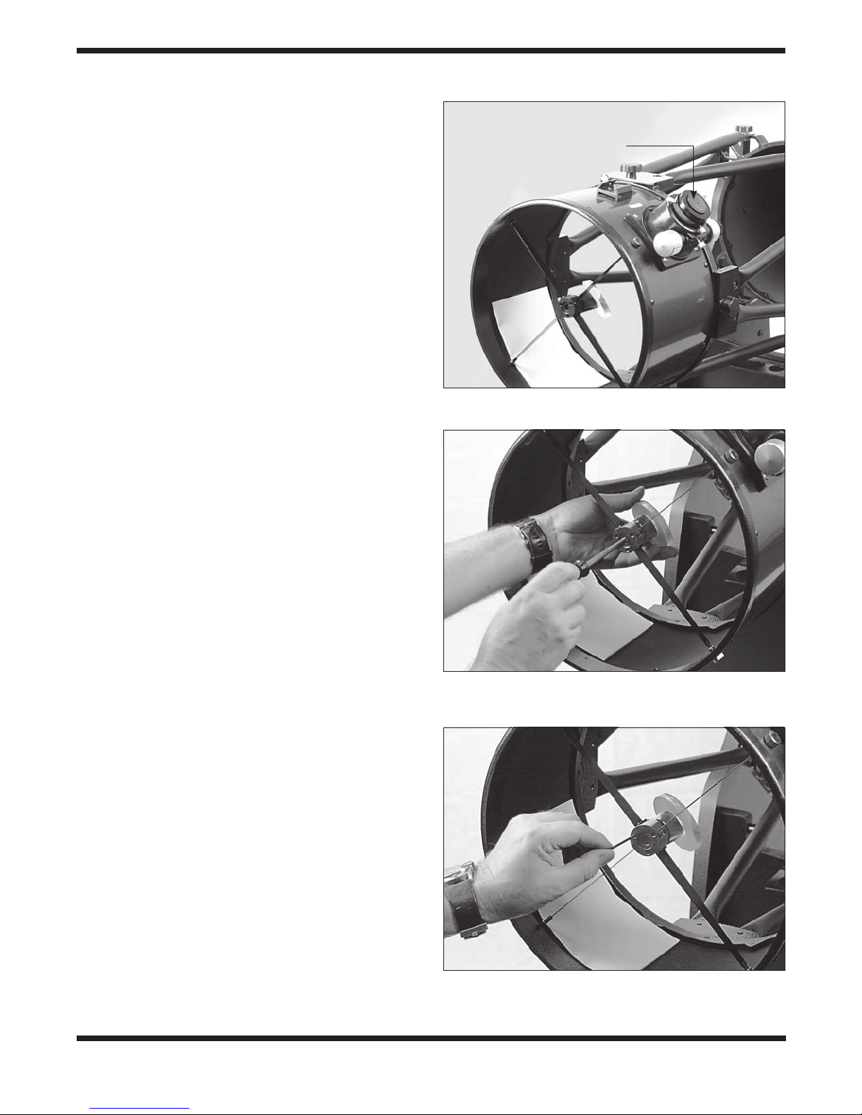
Aligning the Secondary Mirror
With the collimation cap in place, look through the hole in the
cap at the secondary (diagonal) mirror. Ignore the reflections
for the time being. The secondary mirror itself should be centered in the focuser drawtube. If it isn’t, as in Figure 28b, its
position must be adjusted. This positional adjustment of the
secondary mirror will rarely, if ever, need to be done.
To adjust the secondary mirror left-to-right in the focuser drawtube, use the included 2mm hex key to loosen the three small
alignment setscrews in the center hub of the 4-vaned spider
several turns. Now, grasp the mirror to prevent it from rotating
(be careful not to touch the surface of the mirror), while turning the center screw with a Phillips screwdriver (Figure 30).
Turning the screw clockwise will move the secondary mirror
toward the front opening of the optical tube, while turning
the screw counter-clockwise will move the secondary mirror
toward the primary mirror. When the secondary mirror is centered left-to-right in the focuser drawtube, rotate the secondary mirror holder until the reflection of the primary mirror is as
centered in the secondary mirror as possible. It may not be
perfectly centered, but that is OK for now. Tighten the three
small alignment setscrews equally to secure the secondary
mirror in that position.
Note: When making these adjustments, be careful not to
stress the spider vanes or they may bend.
Collimation cap
Figure 29. The SkyQuest optical tube properly set up for
collimation.
The secondary mirror should now be centered in the focuser
drawtube. Now we will shift our attention to the reflections
within the secondary mirror in order to properly adjust the tilt
of the secondary mirror. Adjusting the tilt of the secondary
mirror and the tilt of the primary mirror are the two collimation
adjustments that will be done most often.
If the entire primary mirror reflection is not visible in the secondary mirror, as in Figure 28c, you will need to adjust the tilt
of the secondary mirror. This is done by alternately loosening
one of the three secondary mirror alignment setscrews while
tightening the other two (Figure 31). Do not make excessive
turns of these setscrews or force them past their normal travel. A simple 1/2 turn of the screw can dramatically change the
tilt of the secondary mirror. The goal is to center the primary
mirror reflection in the secondary mirror, as in Figure 28d.
Don’t worry that the reflection of the secondary mirror (the
smallest circle, with the collimation cap “dot” in the center) is
off-center. You will fix that in the next step.
Aligning the Primary Mirror
The final adjustment is made to the tilt of the primary mirror.
It will need adjustment if, as in Figure 28d, the secondary
mirror is centered under the focuser and the reflection of the
primary mirror is centered in the secondary mirror, but the
small reflection of the secondary mirror (with the “dot” of the
collimation cap) is off-center.
Figure 30. To center the secondary mirror under the focuser, hold
the mirror holder in place with one hand while adjusting the center
bolt with a Phillips screwdriver. Do not touch the mirror’s surface!
Figure 31. Adjust the tilt of the secondary mirror by adjusting one
or more of the three alignment setscrews with a 2mm hex key.
17
The tilt of the primary mirror is adjusted with the three large
Out of collimation Collimated
spring-loaded collimation knobs on the rear end of the optical tube (Figure 32). The three smaller thumbscrews lock the
mirror’s position in place. These thumbscrews must be loosened before any collimation adjustments can be made to the
primary mirror.
To start, turn the smaller thumbscrews counterclockwise a
few turns each. Use a screwdriver in the slots, if necessary.
Now, try tightening or loosening one of the collimation knobs
Look into the focuser and see if the secondary mirror reflection has moved closer to the center of the primary mirror. You
can easily determine this with the collimation cap and mirror
center mark by simply watching to see if the “dot” of the collimation cap is moving closer or further away from the “ring”
on the center of the primary mirror. If turning the one knob
does not seem to bring the dot closer to the ring, try using one
of the other collimation knobs. It will take some trial-and-error
using all three knobs to properly align the primary mirror. Over
time you will get the feel for which collimation screws to turn to
move the image in a given direction.
When you have the dot centered as much as is possible in the
ring, your primary mirror is collimated. The view through the
collimation cap should resemble Figure 28e. Re-tighten the
locking thumbscrews in the bottom of the mirror cell.
A simple star test will tell you whether the optics are accurately collimated.
Collimation
knob
Locking
thumbscrew
Figure 32. The tilt of the primary mirror is adjusted by turning one
or more of the three larger thumbscrews. (XX12g shown)
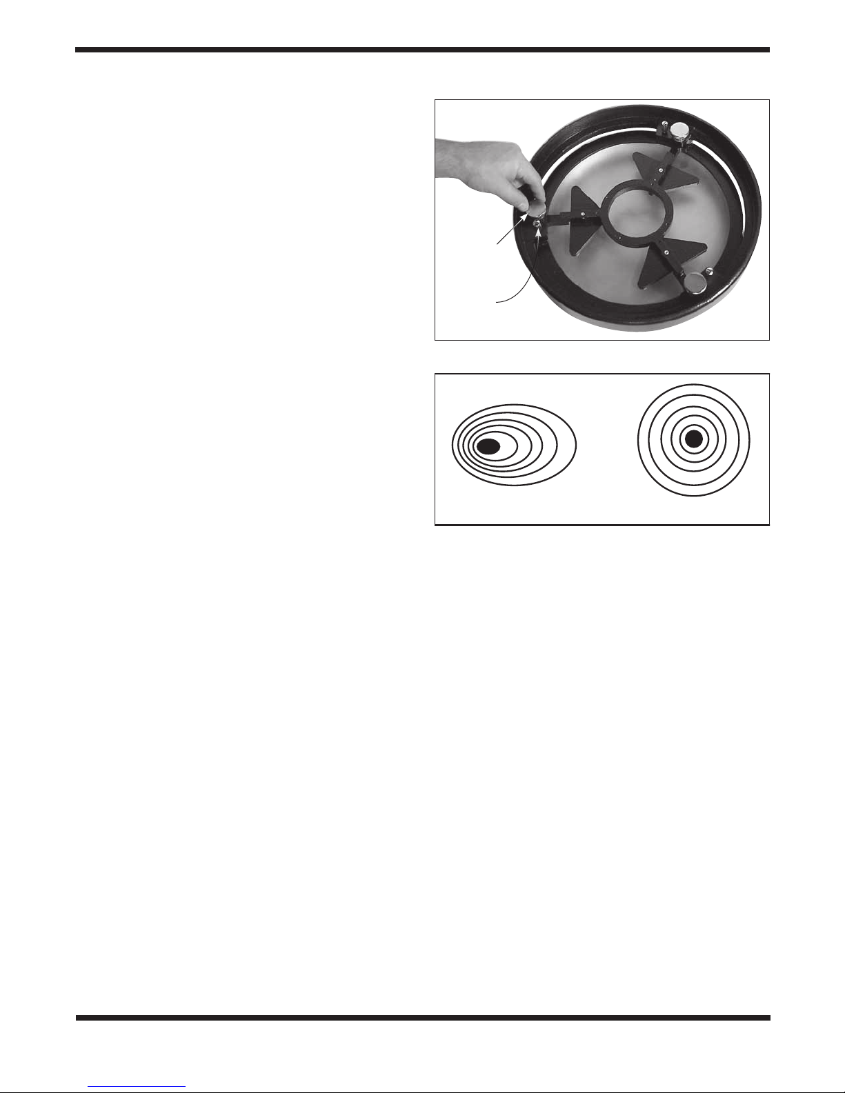
Star-Testing the Telescope
When it is dark, point the telescope at a bright star high in the
sky and center it in the eyepiece’s field of view. Slowly de focus
the image with the focusing knob. If the telescope is correctly collimated, the expanding disk should be a perfect circle
(Figure 33). If the image is unsymmetrical, the telescope is
out of collimation. The dark shadow cast by the secondary mirror should appear in the very center of the out-of-focus circle,
like the hole in a doughnut. If the “hole” appears off center, the
telescope is out of collimation.
If you try the star test and the bright star you have selected is
not accurately centered in the eyepiece, then the optics will
always appear out of collimation, even though they may be
perfectly aligned. It is critical to keep the star centered, so over
time you will need to make slight corrections to the telescope’s
position in order to account for the sky’s apparent motion.
Figure 33. A star test will determine if a telescope’s optics are
properly collimated. An unfocused view of a bright star through
the eyepiece should appear as illustrated on the right if the optics
are perfectly collimated. If the circle is unsymmetrical, as in the
illustration on the left, the scope needs collimation.
5. Using Your Telescope
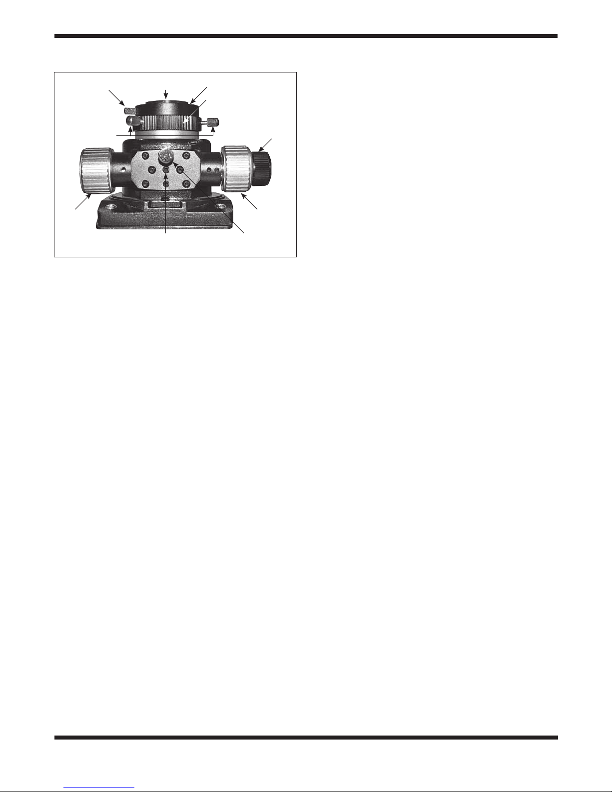
Using the Clutch Tensioning Knobs
The XXg Dobs all now feature large clutch tensioning knobs
on both the altitude and azimuth axes. Located on the altitude and azimuth motor/encoder housings (Figure 34), these
knobs allow the user to adjust the amount of tension (friction) in both the altitude and azimuth motion for moving the
telescope by hand. Rotating the knob clockwise increases
the tension, while turning it counterclockwise decreases the
tension. The closed-loop encoder system of the XXg Dobs
allows the scope to be moved manually without losing the initial GoTo star alignment. The clutch knobs allow you to set the
amount of motion tension on each axis independently to the
level you desire for smooth manual slewing of the telescope.
18

Alt
a. b.
Figure 34. a) The redesigned altitude (Alt) and (AZ) azimuth motor/encoder housings of the XXg Dobs feature large manual clutch knobs for
adjustable motion tension. b) Rotate the clutch knob to adjust the friction of motion for slewing the telescope by hand.
Clutch tensioning knobs
AZ
If a clutch tension it is set too loose, the scope may not slew
on that axis, or may slew intermittently. In that case you
should tighten the clutch knob(s) a little until a normal slewing
motion is achieved. If you add significant weight to the front of
the telescope, such as a heavy eyepiece and finder scope or
a full-aperture glass solar filter, the scope could become “front
heavy.” In that case you may have to tighten the altitude clutch
knob some so that the tube doesn’t slip when moving in the
up/down direction.
Focusing the Telescope
The SkyQuest XXg Dobsonians come standard with a 2"
dual-speed (11:1) Crayford focuser (Figure 27). The focuser
has coarse focus knobs and a fine focus (11:1) knob for very
precise focusing. The focuser allows use of 2" or 1.25" eyepieces and the Crayford design prevents image shift while
focusing.
To focus, with an eyepiece in the focuser and secured with the
thumbscrews, move the telescope so the front end is pointing
in the general direction of an object at least 1/4-mile away.
Now, with your fingers, slowly rotate one of the coarse focus
knobs until the object comes into sharp focus. Go a little bit
beyond sharp focus until the image just starts to blur again,
then reverse the rotation of the knob, just to make sure you’re
close to the focus point.
Now, use the fine focus knob to achieve precise focus. Eleven
turns of the fine focus knob are equivalent to one turn of the
coarse focus knobs, so much finer adjustment is possible
than with just the coarse focus knobs alone. You’ll find this is
a great convenience, especially when attempting to focus at
high magnifications. If you have trouble focusing, rotate the
coarse focusing knob so the drawtube is inward as far as it
will go. Now look through the eyepiece while slowly rotating
the focusing knob in the opposite direction. You should soon
see the point at which focus is reached. The thumbscrew on
the bottom of the focuser body (Figure 27) will lock the focuser drawtube in place, if desired. This is usually not necessary, however. Before focusing, remember to first loosen this
thumbscrew.
If you find the drawtube tension when focusing is either too
tight (i.e., focus knob is difficult to turn) or too loose (i.e.,
drawtube moves by itself under the weight of the eyepiece),
you can adjust it by tightening or loosening the drawtube tensioning setscrew on the focuser, which is located just below
the focus lock thumbscrew (see Figure 27). Adjust this setscrew with the included 2.5mm hex key. Do not loosen the
setscrew too much as there must be some tension to keep the
drawtube secure within the focuser. The other setscrew below
the drawtube tensioning setscrew does not affect drawtube
tension and should not be adjusted.
19

If an image does not come into focus with a particular eyepiece
because you run out of outward focus travel, you may need to
use the included 2" extension adapter. This adapter threads
onto the focuser drawtube. First, you’ll need to remove the 2"
accessory collar from the drawtube by unthreading it (Figure
35a). Then thread the 2" extension adapter into the drawtube
(Figure 35b). Insert a 2" eyepiece into the extension adapter
and secure it with the two thumbscrews. Or, to use 1.25" eyepiece with the extension adapter, insert and secure the 1.25"
adapter in the extension adapter, then insert the eyepiece into
the 1.25" adapter.
Viewing with Eyeglasses
If you wear eyeglasses, you may be able to keep them on
while you observe, if your eyepieces have enough eye relief
to allow you to see the whole field of view. You can try this by
looking through the eyepiece first with your glasses on and
then with them off, and see if the glasses restrict the view
to only a portion of the full field. If they do, you can easily
observe with your glasses off by just refocusing the telescope
as needed. If you suffer from severe astigmatism, however,
you may find images noticeably sharper with your glasses on.
Magnification
Magnification, or power, is determined by the focal length of
the telescope and the focal length of the eyepiece. Therefore,
by using eyepieces of different focal lengths, the resultant
magnification can be varied.
2" accessory
collar
a.
2" extension
adapter
b.
Figure 35. (a) Removing the 2" accessory collar, (b) Thread the
2" extension adapter into the focuser drawtube.
20

Magnification is calculated as follows:
Telescope Focal Length (mm)
Eyepiece Focal Length (mm)
= Magnification
The XX12g, for example, has a focal length of 1500mm. So,
the magnification with the supplied 28mm 2" eyepiece is:
1500mm
28mm
= 54x
The magnification provided by the 12.5mm illuminated eyepiece is:
1500mm
12.5mm
= 120x
The maximum attainable magnification for a telescope is
directly related to how much light its optics can collect. A telescope with more light-collecting area, or aperture, can yield
higher magnifications than a smaller-aperture telescope. The
maximum practical magnification for any telescope, regardless of optical design, is about 50x per inch of aperture. This
translates to about 600x for the XX12g. Of course, such high
magnification will only yield acceptable images if atmospheric
conditions are extremely favorable.
More typically, useful magnifications will be limited to 200x
or less, regardless of aperture. This is because the Earth’s
atmosphere distorts light as it passes through. On nights of
good “seeing,” the atmosphere will be still and will yield the
least amount of distortion. On nights of poor seeing, the atmo-
sphere will be turbulent, which means different densities of
air are rapidly mixing. This causes significant distortion of the
incoming light, which prevents sharp views at high magnifications.
Keep in mind that as magnification is increased, the brightness of the object being viewed will decrease; this is an inherent principle of the physics of optics and cannot be avoided.
If magnification is doubled, an image appears four times dimmer. If magnification is tripled, image brightness is reduced by
a factor of nine!
The SkyQuest XXg Dobs are designed to accept eyepieces
with a barrel diameter of either 1.25" or 2". At low magnifications, 2" eyepieces can provide a wider field of view than standard 1.25" eyepieces. A wider field can be desirable for viewing extended deep-sky objects that are too large to fit within a
narrower field of view.
Using a Light Shroud
We highly recommend using a light shroud over the open
truss tube portion of the optical tube assembly when observing. Usually made of breathable, stretchy, opaque black fabric, a shroud blocks stray light from entering the optical path
at oblique angles, thus improving image contrast. Use of the
shroud will also lessen the accumulation of dust and dirt on
the mirrors during use, and will help prevent dew from forming
on them. A custom-designed light shroud is available for each
of the SkyQquest XXg Dobsonians from Orion.
21

6. Specifications
SkyQuest XX12g GoTo
Primary mirror 305mm diameter, parabolic, center-marked
Focal length 1500mm
Focal ratio f/4.9
Focuser Dual-speed Crayford (11:1), accepts 2" and
1.25" eyepieces with included adapter
Optical tube material Rolled steel
Azimuth bearing Thrust needle bearing
Altitude bearing Ball bearing
Eyepieces 28mm DeepView, 2" barrel; 12.5mm
Illuminated Plössl, 1.25" barrel
Eyepiece
magnifications 54x and 120x
Finder scope EZ Finder II Reflex Sight
Eyepiece rack Holds three 1.25" eyepieces and one 2"
eyepiece
Mirror coatings Enhanced aluminum (94% reflectivity) with
SiO2 overcoat
Minor axis of
secondary mirror 70mm
Optical tube weight
(assembled) 47 lbs.
Base weight 89 lbs.
Tube length 58.3"
Operation Northern or Southern hemisphere
Power requirement 12V DC 2.1 Amp (tip positive)
Motor type DC servo with optical encoders for altitude
and azimuth axes
Slew speeds Rate 0 = 1.0X
Rate 1 = 2X
Rate 2 = 16X
Rate 3 = 32X
Rate 4 = 50X
Rate 5 = 200X
Rate 6 = 400X
Rate 7 = 600X
Rate 8 = 800X
Rate 9 = 1000X
Tracking rates Sidereal (default), Lunar, Solar.
Alignment method Brightest Star, Two Star
Database Over 42,900 objects including:
Complete Messier & Caldwell catalogs, 7840
NGC objects, 5386 IC objects, 29523 SAO
stars, 8 planets, Moon, 212 named stars,
55 well-known double stars, 20 well-known
variable stars, 25 user-defined objects.
SkyQuest XX14g GoTo
Primary mirror 356mm diameter, parabolic, center-marked
Focal length 1650mm
Focal ratio f/4.6
Focuser Dual-speed Crayford (11:1), accepts 2" and
1.25" eyepieces with included adapter
Optical tube material Rolled steel
Azimuth bearing Thrust needle bearing
Altitude bearing Ball bearing
Eyepieces 28mm DeepView, 2" barrel; 12.5mm
Illuminated Plössl, 1.25" barrel
Eyepiece
magnifications 59x and 132x
Finder scope EZ Finder II Reflex Sight
Eyepiece rack Holds three 1.25" eyepieces and one 2"
eyepiece
Mirror coatings Enhanced aluminum (94% reflectivity) with
SiO2 overcoat
Minor axis of
secondary mirror 80mm
Optical tube weight
(assembled) 64 lbs.
Base weight 94 lbs.
Tube length 61"
Operation Northern or Southern hemisphere
Power requirement 12V DC 2.1 Amp (tip positive)
Motor type DC servo with optical encoders for altitude
and azimuth axes
Slew speeds Rate 0 = 1.0X
Rate 1 = 2X
Rate 2 = 16X
Rate 3 = 32X
Rate 4 = 50X
Rate 5 = 200X
Rate 6 = 400X
Rate 7 = 600X
Rate 8 = 800X
Rate 9 = 1000X
Tracking rates Sidereal (default), Lunar, Solar.
Alignment method Brightest Star, Two-Star
Database Over 42,900 objects including:
Complete Messier & Caldwell catalogs, 7840
NGC objects, 5386 IC objects, 29523 SAO
stars, 8 planets, Moon, 212 named stars,
55 well-known double stars, 20 well-known
variable stars, 25 user-defined objects.
22

SkyQuest XX16g GoTo
Primary mirror 406mm diameter, parabolic, center-marked
Focal length 1800mm
Focal ratio f/4.4
Focuser Dual-speed Crayford (11:1), accepts 2" and
1.25" eyepieces with included adapter
Optical tube material Rolled steel
Azimuth bearing Thrust needle bearing
Altitude bearing Ball bearing
Eyepieces 28mm DeepView, 2" barrel; 12.5mm
Illuminated Plössl, 1.25" barrel
Eyepiece
magnifications 64x and 144x
Finder scope EZ Finder II Reflex Sight
Eyepiece rack Holds three 1.25" eyepieces and one 2"
eyepiece
Mirror coatings Enhanced aluminum (94% reflectivity) with
SiO2 overcoat
Minor axis of
secondary mirror 91mm
Optical tube weight
(assembled) 69 lbs.
Base weight 105 lbs.
Tube length 68"
Operation Northern or Southern hemisphere
Power requirement 12V DC 2.1 Amp (tip positive)
Motor type DC servo with optical encoders for altitude
and azimuth axes
Slew speeds Rate 0 = 1.0X
Rate 1 = 2X
Rate 2 = 16X
Rate 3 = 32X
Rate 4 = 50X
Rate 5 = 200X
Rate 6 = 400X
Rate 7 = 600X
Rate 8 = 800X
Rate 9 = 1000X
Tracking rates Sidereal (default), Lunar, Solar.
Alignment method Brightest Star, Two-Star
Database Over 42,900 objects including:
Complete Messier & Caldwell catalogs, 7840
NGC objects, 5386 IC objects, 29523 SAO
stars, 8 planets, Moon, 212 named stars,
55 well-known double stars, 20 well-known
variable stars, 25 user-defined objects.
23

One-Year Limited Warranty
This Orion product is warranted against defects in materials or workmanship for a period of one year from
the date of purchase. This warranty is for the benefit of the original retail purchaser only. During this warranty period Orion Telescopes & Binoculars will repair or replace, at Orion’s option, any warranted instrument that proves to be defective, provided it is returned postage paid. Proof of purchase (such as a copy
of the original receipt) is required. This warranty is only valid in the country of purchase.
This warranty does not apply if, in Orion’s judgment, the instrument has been abused, mishandled, or
modified, nor does it apply to normal wear and tear. This warranty gives you specific legal rights. It is not
intended to remove or restrict your other legal rights under applicable local consumer law; your state or
national statutory consumer rights governing the sale of consumer goods remain fully applicable.
For further warranty information, please visit www.OrionTelescopes.com/warranty.
Orion Telescopes & Binoculars
Corporate Offices: 89 Hangar Way, Watsonville CA 95076 - USA
Customer Support: www.OrionTelescopes.com/contactus
© Copyright 2013 Orion Telescopes & Binoculars
 Loading...