

ORION TELESCOPES & BINOCULARS SkyQuest XT PLUS Dobsonians, 8987 XT10 PLUS, 8974 XT8 PLUS, 8985 XT6 PLUS Instruction Manual
Page 1
INSTRUCTION MANUAL
Orion SkyQuest™ XT PLUS
Dobsonians
#8985 XT6 PLUS, #8974 XT8 PLUS, #8987 XT10 PLUS
#8974
Providing Exceptional Consumer Optical Products Since 1975
All Rights Reserved. No part of this product instruction or any of its contents may be reproduced, copied, modied or adapted,
without the prior written consent of Orion Telescopes & Binoculars.
Customer Support:
www.OrionTelescopes.com/contactus
Corporate Offices:
89 Hangar Way, Watsonville CA 95076 - USA
Copyright © 2013-2014 Orion Telescopes & Binoculars
IN 493 Rev. D 10/17
Page 2
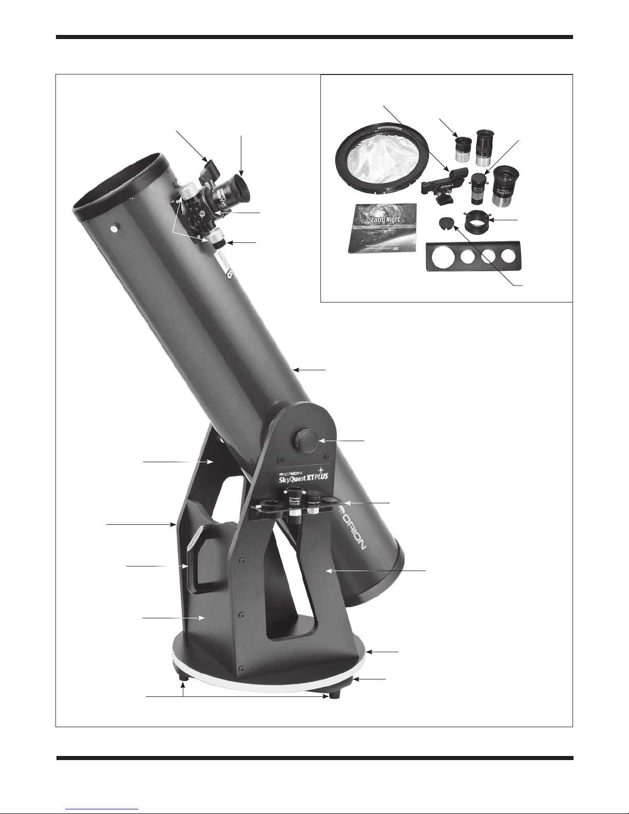
EZ Finder II
Course
focus
knobs
28mm
DeepView
eyepiece
Dual-speed
Crayford
focuser
(XT8 and
XT10)
Fine focus
knob
25mm
Sirius Plössl
eyepiece,
1.25"
(XT6 only)
Shorty 2x
Barlow lens
28mm
DeepView
eyepiece, 2"
(XT8 and
XT10)
2" Extension
adapter (XT8
and XT10)
Collimation
cap
Finder II
Solar
lter
Starry Night
software
digital download
(XT6 and XT8)
EZ
10mm
Sirius Plössl
eyepiece,
1.25"
Eyepiece rack
(XT8 rack shown)
Figure 2. SkyQuest XT PLUS telescopes come with a
terric selection of accessories.
Optical tube
Dobsonian
base
Handle
Front panel
Right side
panel
Feet
Altitude axis
tensioning knob
Eyepiece rack
Left side
panel
Top
groundplate
Bottom
groundplate
Figure 1. The SkyQuest XT8 PLUS 8" Dobsonian
2
Page 3

Welcome to an exciting new world of adventure! Your SkyQuest XT PLUS Dobsonian is a high-quality
optical instrument designed to bring you dazzling views of the universe on any clear night. Easy enough
for an absolute beginner to use, but powerful enough to please even experienced amateur astronomers,
XTPLUS Dobs will provide years of fun discovery for the entire family. They’re packed with great features and useful accessories to insure your enjoyment of these wonderfully capable telescopes. Before
venturing into the night with your new telescope, however, please follow this instruction manual carefully
in order to properly assemble the telescope.
1. Unpacking
The telescope will arrive in two boxes, one containing the
optical tube assembly and accessories, the other containing
the unassembled Dobsonian base. Be careful unpacking the
boxes; we recommend keeping them. In the event that the telescope needs to be shipped to another location, or returned to
Orion for warranty repair, having the proper shipping boxes will
help ensure that your telescope will survive the journey intact.
Make sure all the parts in the Parts List below are present. Be
sure to check the boxes carefully as some parts are small. It is
possible that one or more parts will be found in the box other
than the one it’s listed in. If anything appears to be missing or
broken, immediately call Orion Customer Support (800-676-
1343) for assistance.
Parts List
Box #1: Optical Tube Assembly and Accessories
Qty. Description
1 Optical tube assembly
1 Dust cover
1 10mm Sirius Plössl eyepiece, 1.25" barrel diameter
1 25mm Sirius Plössl eyepiece, 1.25" barrel diameter
(XT6 PLUS only)
1 28mm DeepView 2" eyepiece (XT8 and XT10 PLUS)
1 EZ Finder II with bracket
1 Shorty 2x Barlow lens
1 Safety Film solar lter
1 Quick-collimation cap
1 Eyepiece rack with two ½" mounting screws
2 Altitude axis coupling knobs
1 Low-friction washer (white, 9mm center hole)
1 Metal washer
1 Starry Night software digital download insert
(XT6 and XT8)
Box #2: Dobsonian Base
Qty. Description
1 Left panel
1 Right panel
1 Front brace
1 Top baseplate (round)
1 Ground baseplate (triangular)
12 Base assembly screws (length 2")
3 Plastic feet
3 Wood screws (length 1", for feet)
1 Azimuth axis center bolt, hex head, 3" length
2 20mm diameter washers
4 Bearing cylinders
4 Bearing cylinder machine screws
1 3/8" lock nut
1 Nylon spacer washer (white)
3 Nylon bushings (black) –
17mm, 25mm or 29mm, 33.75mm length
1 Handle
2 Hex-head bolts, 32mm length (for Handle)
2 16mm diameter washers (for Handle)
2 Open-end wrenches
2 Hex keys – size 4mm and 2.5mm
(2.5mm for XT8 and XT10 PLUS)
WARNING: Never look directly at the Sun with the
naked eye or with a telescope – unless you have
a proper solar lter installed over the front of the
telescope! Otherwise, permanent, irreversible eye
damage may result.
Table of Contents
1. Unpacking ............................3
2. Telescope Assembly. . . . . . . . . . . . . . . . . . . . . 4
3. Using Your Telescope .................... 7
4. Collimation ........................... 12
5. Specications .........................15
3
Page 4
2. Telescope Assembly
Assembly of the Dobsonian Base
Now that you have unpacked the boxes and familiarized yourself with all the parts in front of you, it’s time to begin assembly.
The optics of the telescope are already installed in the tube, so
most of the required assembly concerns the Dobsonian base.
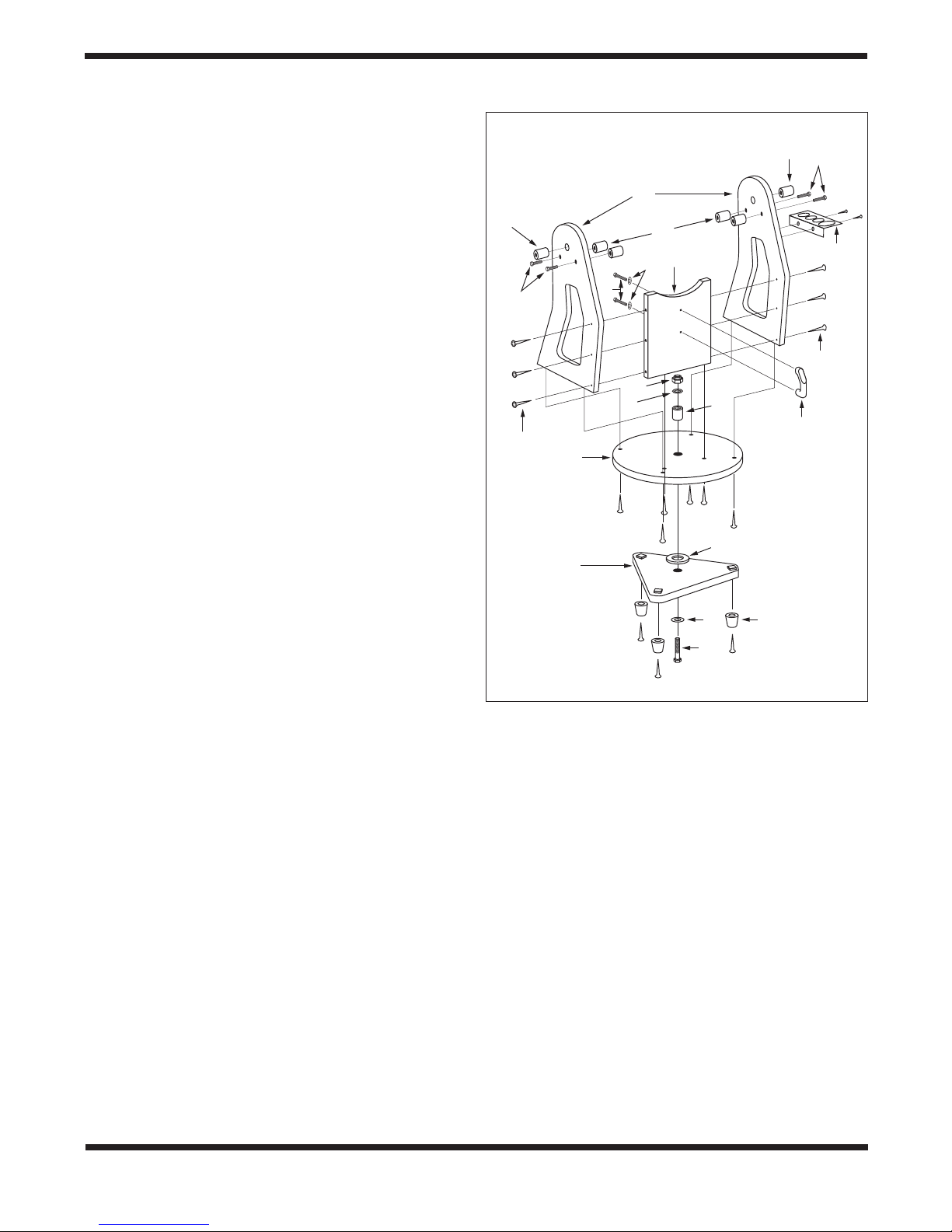
Refer to Figure 3 during base assembly. The base needs to be
assembled only once, unless you disassemble it for long-term
storage. The assembly takes about 30 minutes and requires a
Phillips screwdriver, two included crescent wrenches, and the
included hex key(s).
Note: When tightening the base assembly screws, tighten
them until rm, but be careful not to strip the holes by
over-tightening. If you use an electric screwdriver, do the
nal tightening with a standard screwdriver to avoid stripping.
1. Screw the plastic feet (A) into the underside of the
bottom (triangular) groundplate (B) using the self-tapping
wood screws provided, with a Phillips screwdriver. Insert
the screws through the feet and thread them into the
predrilled starter holes until tight.
2. Loosely attach the front brace (C) to the two side panels
(D) with six of the black base assembly screws (E) in
the predrilled holes. Use the 4mm hex key to tighten
the screws. The side panels should be oriented so the
“SkyQuest XT PLUS” label is facing outward. Do not
completely tighten the screws yet.
3. Line up one of the altitude bearing cylinders (F) with one
of the four bearing cylinder holes on the inside surface
of each side panel. Push a bearing cylinder screw (G)
through the side panel from the outside and thread the
bearing cylinder onto it . You can tighten the cylinder
by hand or, if needed, with the supplied 4mm hex key.
Repeat for the remaining three bearing cylinders.
4. Attach the side and front panel assembly to the top
groundplate (H) with the remaining six base assembly
screws in the predrilled holes. Tighten all six screws.
5. Tighten the six side panel screws installed earlier.
6. Turn the base on its side. Insert the longest (33.75mm)
of the three black plastic bushings (I, see Figure 4) into
the hole in the center of the top groundplate (H). Push
the bushing in so it goes all the way into the groundplate,
sticking out from the bottom surface (Figure 5).
7. Now place the white low-friction spacer washer (J) on
the portion of the bushing sticking out from the bottom
(Figure 5).
8. Install the bottom groundplate (B) by lining up its center
hole with the nylon bushing. The white low-friction spacer
Q
G
Left
D
R
G
Right
R
O
F
C
S
E
M
K
I
N
E
H
J
B
K
A
L
Figure 3. Exploded view of the XT PLUS Dobsonian base
assembly.
washer should now be between the two groundplates
(Figure 5).
9. Put one metal washer (K) onto the hex head bolt (L), then
insert the bolt through the bushing in the center of the
groundplates from the bottom, as shown in Figure 3.
10. Now place the remaining metal washer (K) on the bolt,
followed by the lock nut (M). Use the two crescent
wrenches provided to turn the lock nut with one wrench
while holding the hex bolt’s head with the other, or vice
versa (Figure 6). Tighten the lock nut just enough to allow
a slight separation of the top and bottom groundplates
when the mount is lifted. The purpose of the lock nut
is merely to keep the two groundplates from coming
apart when moving the telescope. Over-tightening the
4
Page 5
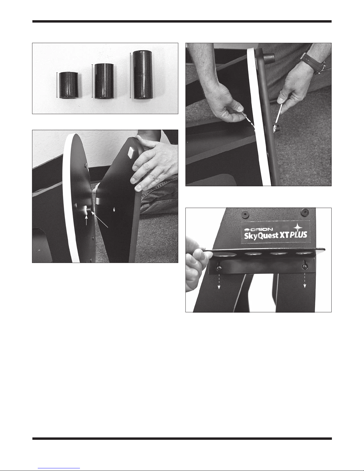
33.75mm
17mm
25mm or 29mm
Figure 4. Three plastic bushings used in the assembly of
the XT PLUS.
Figure 6. Use the two included open-end wrenches
as shown to attach the bottom groundplate to the top
groundplate.
Low-
friction
washer
33.75mm
bushing
Figure 5. Assembly of the groundplates.
lock nut will make the base difficult to rotate in the
azimuthal (horizontal) direction.
11. To attach the handle (N) to the front brace, rst place a
washer (O) onto each of the two 32mm hex-head bolts
(P). Then insert the bolts through the holes in the front
panel (from the inside surface) and into the threaded
holes in the handle. Tighten the bolts with a crescent
wrench.
12. In the hole near the top of the left side panel (D-Left)
insert the shortest (17mm) of the three black plastic
bushings (Q). In the hole near the top of the right side
panel (D-Right) insert the middle-sized (25mm or 29mm)
of the three black plastic bushings (R). The latter bushing
(R) is longer than the width of the side panel by 1/4" or
so – that’s by design.
Figure 7. Place the eyepiece rack’s “keyholes” over the
mounting screws, then press the rack downward and tighten
the screws. (XT8 PLUS rack shown)
13. To install the eyepiece rack (S), nd the two pilot
holes on the left side panel, and screw one of the ½"
wood screws into each hole until the screw heads are
about 1/8" from the panel’s surface. Then “keyhole” the
eyepiece rack onto the wood screws and tighten the
screws to secure the rack in place (Figure 7).
5
Page 6

Telescope
side bearings
Low-friction
washer
Metal
washer
Bearing
cylinders
(x4)
Figure 8. Gently set the telescope into the base by resting
the side bearings of the telescope on the bearing cylinders.
Installing the Optical Tube Assembly on the Base
1. Lift the optical tube and gently place it into the Dobsonian
base so that the altitude bearings on either side of the
tube rest on the bearing cylinders (Figure 8) . Take care
when lowering the telescope not to catch the ring of
reddish material attached to the telescope tube’s left
side bearing on the top edge of the base’s left side
panel, or the ring could come off (it is held on the
side bearing with adhesive). Make sure the optical tube
is oriented as shown, with the focuser facing the left side
panel. Once the tube is resting on the bearing cylinders,
the tube should pivot freely up and down with gentle
hand pressure. Note that the tube will not yet be properly
balanced, since the eyepiece and EZ Finder II are not in
place, and the altitude axis coupling knobs are not yet
installed.
2. Now insert the bolt of one of the altitude axis coupling
knobs through the bushing in the RIGHT side panel and
turn the knob to thread the bolt into the threaded insert
Figure 9. Assembling the tensioning knob. First place a
metal washer on the bolt, then thread on the white, lowfriction washer until it is all the way on. Both washers will now
be held captive on the bolt.
Left
side panel
Tensioning
knob
Figure 10. The tensioning knob on the left side panel lets
you set and adjust the amount of friction for the altitude
motion of the telescope.
of the tube assembly’s right side bearing. Thread the bolt
until it stops and the knob is lightly tightened.
3. On the other altitude axis coupling knob place a metal
washer on the bolt, then thread on the white plastic
washer all the way (Figure 9), until it is captive on the
smooth portion of the shaft nearest the hand knob. Now
insert the bolt though the bushing on the LEFT side
panel and use the knob to thread it into the left side
bearing on the optical tube assembly. This coupling knob
is referred to as the “tensioning knob” (Figure 10).
6
Page 7

Power
knob
Altitude
adjustment
knob
Thumbscrews
Figure 11. The EZ Finder II reex sight.
Thumbscrew
Dovetail
mounting shoe
Battery
casing
Azimuth
adjustment
knob
Dovetail
mounting
bracket
E
D
U
T
I
T
L
A
Figure 12. Slide the EZ Finder II into the dovetail shoe and
secure it with the thumbscrew. Note the correct orientation of
the EZ Finder.
Installing the EZ Finder II
Before installing the EZ Finder II on the telescope, you’ll need
to insert the included 3-volt lithium battery.
1. Insert a small, at-blade screwdriver into the notch in the
battery casing and gently pry it off (Figure 11).
2. Slide the CR2032 3V lithium battery under the retaining
clip with the positive (+) side facing down (touching the
clip).
3. Then press the battery casing back on.
Should the battery die, replacement CR2032 batteries are
available at many stores where small batteries are sold.
To attach the dovetail mounting bracket to the EZ Finder II,
loosen the two thumbscrews on the bottom rail of the EZ
Finder II. Slide the EZ Finder II onto the bracket and tighten
the two thumbscrews. Then simply slide the dovetail mounting
bracket into the telescope’s dovetail mounting shoe as shown
in Figure 12 and tighten the thumbscrew on the shoe to secure
the mounting bracket.
A
Z
I
M
H
T
U
Figure 13. XT PLUS Dobsonians are “hands on”
telescopes that have two directions of movement: altitude
(up/down) and azimuth (left/right). Just grasp the front of the
telescope and move it to the desired point in the sky.
3. Using Your Telescope
It is best to get a feel for the basic functions of the SkyQuest
XT PLUS Dobsonian during the day, before observing astronomical objects at night. This way you will not have to fumble around trying to orient yourself in the dark! Find a spot
outdoors where you have plenty of room to move around the
telescope, and where you have a clear view of some object
or vista that is at least 1/4-mile away. It is not critical that the
base be exactly level, but it should be placed on somewhat
at ground or pavement to ensure smooth movement of the
telescope.
Moving the Telescope
The Dobsonian design permits easy manual movement of the
telescope in the altitude (up / down) and azimuth (left / right)
directions (Figure 13). The azimuth motion should be smooth,
with fairly little resistance if the lock nut on the base’s center
7
Page 8

1.25" Collar
Thumbscrew
(x2)
Focus
knob
Focus
knob
a.
1.25" adapter
Focus lock
thumbscrew
Drawtube
tensioning
setscrew
b.
Coarse focus knobs
2" accessory
collar
Fine focus
knob (11:1)
Figure 14. (a) The XT6 PLUS has a 1.25" rack-and-pinion
focuser, (b) The XT8 and XT10 PLUS are equipped with a 2"
dual speed Crayford focuser.
bolt is not over-tightened. For the altitude motion, the tension
can be adjusted to the desired level with the altitude axis tensioning knob near the top of the left side panel.
To move the telescope, you simply grasp the front end of the
tube and move the scope where you want it to point. If the tube
drifts up or down when you let go of it, you will need to increase
the friction by turning the altitude tensioning knob clockwise.
Focusing
The focuser on the XT6 PLUS is a 1.25" rack-and-pinion type
(Figure 14a), which accepts only 1.25" eyepieces. The XT8
2" accessory
collar
a.
2" extension
adapter
b.
Figure 15. (a) Removing the 2" accessory collar (XT8 y
XT 10 PLUS only), (b) Thread the 2" extension adapter into
the focuser drawtube.
and XT10 PLUS come standard with a 2" dual-speed Crayfordtype gearless focuser (Figure 14b). The large 2" format fo-
cuser allows use of 2" or 1.25" eyepieces and the Crayford
design prevents imaging shifting while focusing. The ne focus
(11:1) knob on the Crayford focuser allows one to make very
tiny focusing increments for ultra-precise focusing.
To focus, insert an eyepiece into the focuser and secure it with
the thumbscrew(s). Now slowly rotate one of the coarse focus
knobs until a distant object comes into sharp focus. Go a little
bit beyond sharp focus until the image just starts to blur again,
then reverse the rotation of the knob, just to make sure you’re
zeroing in on the exact focus point.
For the XT8 and XT10 PLUS, use the smaller, ne focus knob
to achieve precise focus. Eleven turns of the ne focus knob
8
Page 9

Figure 16. The EZ Finder II superimposes a small red dot
(it’s not a laser!) on a non-magnied eld of view, which helps
to center an object in the telescope’s eld of view.
is equivalent to one turn of the coarse focus knobs (11:1), so
much ner adjustment is possible than with just the coarse
focus knobs alone. You’ll find this is a great convenience,
especially when attempting to focus at high magnications.
With either telescope, if you have trouble focusing, rotate the
coarse focusing knob so the drawtube is inward as far as it
will go. Now look through the eyepiece while slowly rotating
the coarse focusing knob in the opposite direction. You should
soon see the point at which focus is reached. The thumbscrew
on the bottom of the focuser body (Figure 14b) will lock the fo-
cuser drawtube in place, if desired (XT8 and XT10 PLUS). This
is usually not necessary, however. Before focusing, remember
to rst loosen this thumbscrew.
The following applies to the XT8 and XT10 PLUS focusers only:
If you nd the drawtube tension when focusing is either too
tight (i.e., focus knob is difficult to turn) or too loose (i.e., drawtube moves by itself under the weight of the eyepiece), you
can adjust it by tightening or loosening the drawtube tensioning setscrew on the focuser, which is located just below the
focus lock thumbscrew (see Figure 14b). Adjust this setscrew
with the included 2.5mm hex key. Do not loosen the setscrew
too much as there must be some tension to keep the drawtube
secure within the focuser. The other setscrew below the drawtube tensioning setscrew does not affect drawtube tension and
should not be adjusted.
If an image does not come into focus with a particular eyepiece because you run out of outward focus travel, you may
need to use the included 2" extension adapter. This adapter
threads onto the focuser drawtube. First, you’ll need to remove
the 2" accessory collar from the drawtube by unthreading it
(Figure 15a). Then thread the 2" extension adapter into the
drawtube (Figure 15b). Insert a 2" eyepiece into the exten-
sion adapter and secure it with the two thumbscrews. Or, to
use 1.25" eyepiece with the extension adapter, insert the 1.25"
adapter into the extension adapter, then insert the eyepiece
into the 1.25" adapter.
Using the EZ Finder II
The EZ Finder II works by projecting a tiny red dot (it’s not a
laser beam!) onto a lens mounted in the front of the unit. When
you look through the EZ Finder II, the red dot will appear to oat
in space, helping you locate your target object (Figure16). The
red dot is produced by a light-emitting diode (LED) near the
rear of the unit.
Turn the power knob (see Figure 11) clockwise until you hear
the “click” indicating that power has been turned on. Look
through the back of the reex sight with both eyes open to see
the red dot. Position your eye at a comfortable distance from
the back of the sight. In daylight you may need to cover the
front of the sight with your hand to be able to see the dot, which
is purposefully quite dim. The intensity of the dot is adjusted by
turning the power knob. For best results when stargazing, use
the dimmest possible setting that allows you to see the dot
without difficulty. Typically a dimmer setting is used under dark
skies and a bright setting is used under light-polluted skies or
in daylight.
At the end of your observing session, be sure to turn the power
knob counterclockwise until it clicks off.
Aligning the EZ Finder II
When the EZ Finder II is properly aligned with the telescope,
an object that is centered on the EZ Finder II’s red dot should
also appear in the center of the eld of view of the telescope’s
eyepiece. Alignment of the EZ Finder II is easiest during daylight, before observing at night. Aim the telescope at a distant
object such as a telephone pole or roof chimney and center it
in the telescope’s eyepiece. The object should be at least ¼
mile away. Now, with the EZ Finder II turned on, look though
the EZ Finder II. The object should appear in the eld of view.
Without moving the main telescope, use the EZ Finder II’s azimuth (left/right) and altitude (up/down) adjustment knobs (see
Figure 11) to position the red dot on the object in the eyepiece.
When the red dot is centered on the distant object, check to
make sure that the object is still centered in the telescope’s
eld of view. If not, re-center it and adjust the EZ Finder II’s
alignment again. When the object is centered in BOTH the
eyepiece and the EZ Finder’s red dot, the EZ Finder II is properly aligned with the telescope. Once aligned, the
EZ Finder II will usually hold its alignment even after being
removed and remounted. Otherwise, only minimal realignment
will be needed.
Now that the EZ Finder II is aligned, the telescope can be
quickly and accurately pointed at anything you wish to observe.
The EZ Finder II has a much wider eld of view than the telescope’s eyepiece, and therefore it is much easier to rst center an object in the EZ Finder II. Then, if the EZ Finder II is
accurately aligned, the object will also be centered in the telescope’s eld of view.
9
Page 10

Figure 18. Do not attempt to carry the fully assembled
telescope by the handle on the base! The front of the optical
tube could contact the ground and damage the tube, the
focuser, and any attached accessories. (XT8 PLUS shown)
Figure 17. A proper way to carry the telescope, with tube
assembly uncoupled from the base. (XT8 PLUS shown)
Magnication
Magnication, or power, is determined by the focal length of the
telescope and the focal length of the eyepiece. Magnication is
calculated as follows:
Telescope Focal Length (mm)
Eyepiece Focal Length (mm)
= Magnication
Magnication of the telescope can be changed by using different eyepieces. The XT8 PLUS has a focal length of 1200mm.
So, the magnication with the supplied 10mm eyepiece is:
1200mm
10mm
= 120x
By the same formula, when using the 28mm DeepView eyepiece
the magnication would be 42.9x.
The maximum attainable magnication for a telescope is directly
related to how much light its optics can collect. A telescope with
more light-collecting area, or aperture, can yield higher magnications than a smaller aperture telescope. The maximum practical magnication for any telescope, regardless of optical design,
is about 60x per inch of aperture. This translates to about 480x
for the XT8 PLUS.
Keep in mind that as magnication is increased, the brightness of the object being viewed will decrease; this is an inherent principle of the physics of optics and cannot be avoided. If
magnication is doubled, an image appears four times dimmer.
If magnication is tripled, image brightness is reduced by a
factor of nine!
Note About High Magnications:
Maximum magnications are achieved only under the most
ideal viewing conditions at the best observing sites. Most of
the time, magnications are limited to 200x or less, regardless of aperture. This is because the Earth’s atmosphere distorts light as it passes through. On nights of good “seeing,” the
atmosphere will be still and will yield the least amount of distortion. On nights of poor seeing, the atmosphere will be turbulent, which means different densities of air are rapidly mixing.
This causes signicant distortion of the incoming light, which
prevents sharp views at high magnications. The sharpest
images will always be achieved at lower magnications.
Tube Balance
The SkyQuest XT PLUS tube is held on the Dobsonian base
with two altitude axis coupling knobs (Figure 10). The one on
the right side acts simply as a retaining knob, while the one on
the left side is the “tensioning” knob. Turning this knob clockwise pulls the telescope’s left side bearing into the left side
panel, increasing the friction between the side bearing’s ber
ring and the melamine surface of the side panel. The tighter
the knob is turned, the greater the friction and the stiffer the
tube will become to move up and down. Ideally you’ll want
to set the tension such that the tube moves relatively freely,
so that you can “track” objects smoothly by moving it in small
increments while viewing through the eyepiece.
If using heavier accessories on the front of the scope, increasing the tension on the altitude axis will prevent the front of the
scope from sagging under the weight. That is, you can “adjust
out” a modest scope imbalance by increasing the tension via
the tensioning (left) knob.
10
Page 11

Eyepiece
Barlow
1.25"
adapter
Figure 19. The Shorty 2x Barlow is installed in the
focuser’s 1.25" adapter and accepts any 1.25" eyepiece,
doubling its magnication.
Carrying/Transporting the Telescope
Moving the SkyQuest XT PLUS is easy to do. We recommend
detaching the telescope tube from the base and carrying the two
pieces separately, as in Figure 17. We DO NOT recommend car-
rying the entire telescope – with the tube still attached to the
base – by the handle on the base’s front panel! If you do, the
telescope tube could swing downward and contact the ground
(Figure 18).
CAUTION – When removing the altitude axis coupling knobs,
make sure that the black bushings do not fall out and get lost!
Either remove them along with the knobs and keep them all
together, or leave the bushings in the holes – but make sure
they do not fall out.
When transporting the XT PLUS in a vehicle, be sure to isolate
the optical tube assembly so that it cannot slide or roll, which
could dent the tube. We recommend transporting and storing
the tube assembly in a padded case for protection.
Finally, keep the dust cover on the front of the telescope when
the telescope is not in use. Doing so will keep dust from accumulating on the primary mirror.
Using the Shorty 2x Barlow Lens
The Shorty 2x Barlow included with your SkyQuest XT PLUS
will double the magnication of any 1.25" eyepiece it is used
with. It effectively increases the number of available magnication options at your disposal, depending on how many 1.25"
eyepieces you have.
You just insert the Barlow into the 1.25" adapter and secure
it with the thumbscrew. Then insert a 1.25" eyepiece into the
Barlow and secure it with the thumbscrew on the Barlow
Figure 20. The included Safety Film Solar Filter snaps onto
the front of the telescope for safe viewing of our Sun through
the telescope eyepiece. DO NOT look through the EZ Finder
II to center the Sun in the telescope’s eld of view!
(Figure 19). Finally, adjust the focus as necessary using the
telescope’s focus wheels to achieve a sharp image.
Using the Safety Film Solar Filter
Also included with your XT PLUS is a Safety Film Solar Filter
that permits daytime viewing of our nearest star, the Sun
(Figure 20). The white-light lter uses high-quality Baader
Astro Solar safety lm, which reduces the transmission of the
Sun’s radiation to a safe level, allowing great views of sunspots,
solar eclipses, and planetary transits of our Sun. Through the
lter the Sun appears in its natural color – a neutral white color,
without any orange or blue tinting seen with some other types
of solar lter material. Don’t worry if the material appears “wrinkled” or wavy; this is normal and does not adversely affect the
image seen through the lter!
DO NOT try to center the Sun’s disk in the main telescope
by viewing through the EZ Finder II! Only a nder scope
equipped with a proper solar lter, or a special solar aiming
device, should be used. A good way to “nd” the Sun in your
telescope is to point the scope (with solar lter in place!) in the
general direction of the Sun, then with a wide-eld eyepiece in
the focuser slowly sweep the area until you glimpse the Sun’s
disk in the eyepiece. It’s best to focus the telescope on a distant object before attaching the solar lter, because with the
solar lter in place you will not see anything except the Sun’s
disk – and if you’re way out of focus you may not even see that!
DO keep the solar lter in its box when not in use to protect it
from damage. If you notice even the smallest tear or breach
in the solar lm material, DO NOT LOOK THROUGH THE
TELESCOPE! Permanent eye damage could result. Call Orion
Customer Support for assistance.
11
Page 12

Figure 21. The quick collimation cap, which features a
reective inner surface, helps in centering reections of the
optics in the focuser during the collimation process.
a.
b. c.
Figure 22. The telescope ready for collimation, with the
tube oriented horizontally, the collimation cap in place on the
focuser, and a piece of white paper placed inside the tube
opposite the focuser.
4. Collimation
Collimation is the process of adjusting the mirrors so they are
correctly aligned with one another. Your telescope’s optics
were aligned at the factory, but they could become misaligned
during shipment. Accurate mirror alignment is important to
ensure the peak performance of your telescope, so it should
be checked regularly. Collimation is relatively easy to do and
can be done in daylight.
The Collimation Cap and Mirror Center Mark
Your XT PLUS comes with a “quick-collimation” cap (Figure
21). This is a simple cap that ts on the focuser drawtube like a
12
d. e.
Figure 23. Collimating the optics. (a) When the mirrors are
properly aligned, the view down the focuser drawtube should
look like this; (b) With the collimation cap in place, if the
optics are out of alignment, the view might look something
like this; (c) Here, the secondary mirror is centered under
the focuser, but it needs to be adjusted (tilted) so that the
entire primary mirror is visible; (d) The secondary mirror
is correctly aligned, but the primary mirror still needs
adjustment. When the primary mirror is correctly aligned, the
“dot” will be centered, as in (e).
dust cap, but has a hole in the center and a reective material
on the underside. The cap helps center your eye so that col-
Page 13

Secondary
collimation
thumbscrews
Center
screw
Spider
vanes
Secondary
mirror
Figure 24. The secondary mirror and “spider.” The XT
PLUS features three thumbscrews for easy adjustment of the
secondary mirror tilt.
limation is easy to perform. Figures 23a through 23e assume
you have the collimation cap in place.
You will notice a tiny ring (sticker) in the exact center of the
primary mirror. This “center mark” allows you to achieve a
very precise collimation of the primary mirror; you don’t have
to guess where the center of the mirror is. You simply adjust
the mirror position (described below) until the reection of the
hole in the collimation cap is centered inside the ring. This center mark is also required for best results with other collimating
devices, such as Orion’s LaserMate Deluxe Laser Collimator.
Note: The center ring sticker need not ever be removed
from the primary mirror. Because it lies directly in the
shadow of the secondary mirror, its presence in no way
adversely affects the optical performance of the telescope
or the image quality. That might seem counterintuitive, but
it’s true!
Preparing the Scope for Collimation
Once you get the hang of collimation, you will be able to do it
quickly even in the dark. When trying it for the rst time or two,
though, it is best to collimate in daylight, preferably in a brightly
lit room and with the telescope aimed at a white wall. It is recommended that the telescope tube be oriented horizontally.
This will prevent any parts from the secondary mirror from falling down onto the primary mirror and causing damage, should
something come loose when you are making adjustments.
Place a sheet of white paper inside the optical tube directly
opposite the focuser. This will provide a bright “background”
when viewing into the focuser. When properly set up for collimation, your telescope should resemble Figure 22.
To check the scope’s collimation, remove the eyepiece and look
down the focuser drawtube. You should see the secondary mirror
centered in the drawtube, as well as the reection of the primary
mirror centered in the secondary mirror, and the reection of the
secondary mirror (and your eye) centered in the reection of the
a.
b.
Figure 25. (a) To center the secondary mirror under the
focuser, hold the secondary mirror holder in place with
one hand while adjusting the center bolt with a Phillips
screwdriver. Do not touch the mirror’s surface! (b) Adjust
the tilt of the secondary mirror by loosening or tightening the
three alignment thumbscrews.
primary mirror, as in Figure 23a. If anything is off-center, as in
Figure 23b, proceed with the following collimation procedure.
Aligning the Secondary Mirror
With the collimation cap in place, look through the hole in the
cap at the secondary (diagonal) mirror. Ignore the reections
for the time being. The secondary mirror itself should be centered in the focuser drawtube, in the direction parallel to the
length of the telescope. If it is, you can skip the next two
paragraphs. If it isn’t, as in Figure 23b, it must be adjusted.
This adjustment will rarely, if ever, need to be done.
The secondary mirror is bonded to a holder held by four “spider” vanes (Figure 24). While holding the secondary mirror
holder with one hand, being careful not to touch the surface
of the mirror, loosen the three secondary mirror collimation
thumbscrews a couple of turns each. Now, with a Phillips
screwdriver, turn the center screw of the holder to move it forward or back (Figure 25a). Turning the screw clockwise will
move the secondary mirror toward the front opening of the
optical tube, while turning the screw counter-clockwise will
move the secondary mirror toward the primary mirror.
Note: When making these adjustments, be careful not to
stress the spider vanes or they may bend.
When the secondary mirror is centered in the focuser drawtube, rotate the secondary mirror holder until the reection of
the primary mirror is as centered in the secondary mirror as
13
Page 14

Locking
thumbscrew
Collimation
thumbscrew
Figure 26. The tilt of the primary mirror is adjusted by
turning one or more of the three larger thumbscrews. The
three small thumbscrews lock the primary mirror in place
and must be loosened before any adjustments can be
made, then re-tightened (lightly) once the primary mirror
has been adjusted.
possible. It may not be perfectly centered, but that is OK. Now
re-tighten the three secondary mirror collimation thumbscrews
equally to secure the secondary mirror in that position.
If the entire primary mirror reection is not visible in the secondary mirror, as in Figure 23c, you will need to adjust the tilt
of the secondary mirror. This is done by alternately loosening
one of the three alignment thumbscrews while lightly tightening the other two (Figure 25b). Do not make excessive turns
of these thumbscrews or force them past their normal travel.
A mere 1/4 turn of the screw can dramatically change the tilt
of the mirror. The goal is to center the primary mirror reection
in the secondary mirror, as in Figure 23d. Don’t worry that the
reection of the secondary mirror (the smallest circle, with the
collimation cap “dot” in the center) is off-center. You will x that
in the next step.
Adjusting the Primary Mirror
The nal adjustment is made to the primary mirror. It will need
adjustment if, as in Figure 23d, the secondary mirror is cen-
tered under the focuser and the reection of the primary mirror
is centered in the secondary mirror, but the small reection of
the secondary mirror (with the “dot” of the collimation cap) is
off-center.
The tilt of the primary mirror is adjusted with three springloaded collimation thumbscrews on the back end of the optical
tube (bottom of the primary mirror cell); these are the larger
thumbscrews (Figure 26). The three smaller thumbscrews
Figure 27. A star test will determine if a telescope’s optics
are properly collimated. An unfocused view of a bright star
through the eyepiece should appear as illustrated on the
right if the optics are perfectly collimated. If the circle is
unsymmetrical, as in the illustration on the left, the scope
needs collimation.
lock the mirror’s position in place; these thumbscrews must be
loosened before any collimation adjustments can be made to
the primary mirror.
To start, turn the smaller thumbscrews a few turns each.
Now, try tightening or loosening one of the large collimation
thumbscrews with your ngers. Look into the focuser and see if
the secondary mirror reection has moved closer to the center
of the primary. You can tell this easily with the collimation cap
and mirror center mark by simply watching to see if the “dot” of
the collimation cap is moving closer or farther away from the
ring on the center of the primary mirror. When you have the
dot centered as much as possible in the ring, your primary mirror is collimated. The view through the collimation cap should
resemble Figure 23e. Retighten the locking thumbscrews.
A simple star test will tell you whether the optics are accurately
collimated.
Star-Testing the Telescope
When it is dark, point the telescope at a bright star and accurately center it in the eyepiece’s eld of view. Slowly de-focus
the image with the focusing knob. If the telescope is correctly
collimated, the expanding disk should be a perfect circle
(Figure 27). If the image is unsymmetrical, the scope is out
of collimation. The dark shadow cast by the secondary mirror
should appear in the very center of the out-of-focus circle, like
the hole in a donut. If the “hole” appears off-center, the telescope is out of collimation.
If you try the star test and the bright star you have selected is
not accurately centered in the eyepiece, the optics will always
appear out of collimation, even though they may be perfectly
aligned. It is critical to keep the star centered, so over time you
will need to make slight corrections to the telescope’s position
in order to account for the sky’s apparent motion.
14
Page 15

5. Specifications
SkyQuest XT6 PLUS
Primary mirror
focal length: 1200mm
Primary mirror
diameter: 150mm
Minor axis of
secondary mirror: 34mm
Optics: Parabolic, diffraction limited
Mirror coatings: Enhanced aluminum (94%
reectivity), with SiO
overcoat
2
Focal Ratio: f/8.0
Focuser: 2" Crayford, dual-speed (11:1),
accepts 2" eyepieces and 1.25"
eyepieces with included adapter
Optical tube
material: Rolled steel
Eyepieces: 10mm Sirius Plössl, 1.25" barrel dia.
25mm Sirius Plössl, 1.25" barrel dia.
Magnication with
supplied eyepieces: 120x (10mm Sirius)
48x (25mm Sirius)
Reex sight: EZ Finder II
Optical tube weight: 11.5 lbs.
Base weight: 21.9 lbs.
Tube length: 46"
Tube outer diameter: 7.28"
Cooling fan: Optional, ready to mount
SkyQuest XT8 PLUS
Primary mirror
focal length: 1200mm
Primary mirror
diameter: 203mm
Minor axis of
secondary mirror: 47.0mm
Optics: Parabolic, diffraction limited
Mirror coatings: Enhanced aluminum (94%
reectivity), with SiO
overcoat
2
Focal Ratio: f/5.9
Focuser: 2" Crayford, dual-speed (11:1),
accepts 2" eyepieces and 1.25"
eyepieces with included adapter
Optical tube
material: Rolled steel
Eyepieces: 10mm Sirius Plössl, 1.25" barrel dia.
28mm DeepView, 2" barrel dia.
Magnication with
supplied eyepieces: 120x (10mm Sirius)
43x (28mm DeepView)
Reex sight: EZ Finder II
Optical tube weight: 20.3 lbs.
Base weight: 21.3 lbs.
Tube length: 46.5"
Tube outer diameter: 9.25"
Cooling fan: Optional, ready to mount
SkyQuest XT10 Plus
Primary mirror
focal length: 1200mm
Primary mirror
diameter: 254mm
Minor axis of
secondary mirror: 63.0mm
Optics: Parabolic, diffraction limited
Mirror coatings: Enhanced aluminum (94%
reectivity), with SiO
overcoat
2
Focal Ratio: f/4.7
Focuser: 2" Crayford, dual-speed (11:1),
accepts 2" eyepieces and 1.25"
eyepieces with included adapter
Optical tube material: Rolled steel
Eyepieces: 10mm Sirius Plössl, 1.25" barrel dia.
28mm DeepView, 2" barrel dia.
Magnication with
supplied eyepieces: 120x (10mm Sirius)
43x (28mm DeepView)
Reex sight: EZ Finder II
Optical tube weight: 30 lbs.
Base weight: 23 lbs.
Tube length: 47.5"
Tube outer diameter: 12.25"
Cooling fan: Optional, ready to mount
15
Page 16

One-Year Limited Warranty
This Orion product is warranted against defects in materials or workmanship for a period of one year
from the date of purchase. This warranty is for the benet of the original retail purchaser only. During this
warranty period Orion Telescopes & Binoculars will repair or replace, at Orion’s option, any warranted
instrument that proves to be defective, provided it is returned postage paid. Proof of purchase (such as a
copy of the original receipt) is required. This warranty is only valid in the country of purchase.
This warranty does not apply if, in Orion’s judgment, the instrument has been abused, mishandled, or
modied, nor does it apply to normal wear and tear. This warranty gives you specic legal rights. It is not
intended to remove or restrict your other legal rights under applicable local consumer law; your state or
national statutory consumer rights governing the sale of consumer goods remain fully applicable.
For further warranty information, please visit www.OrionTelescopes.com/warranty.
Orion Telescopes & Binoculars
Corporate Offices: 89 Hangar Way, Watsonville CA 95076 - USA
Customer Support: www.OrionTelescopes.com/contactus
Copyright © 2013-2014 Orion Telescopes & Binoculars
All Rights Reserved. No part of this product instruction or any of its contents may be reproduced, copied, modied or adapted, without the prior
written consent of Orion Telescopes & Binoculars.
16
 Loading...