

Page 1

INSTRUCTION MANUAL
IN 211 Rev. A 10/02
Providing Exceptional Consumer Optical Products Since 1975
Customer Support (800)676-1343
E-mail: support@telescope.com
Corporate Offices (831)763-7000
P.O. Box 1815, Santa Cruz, CA 95061
Orion
®
Observer™70 EQ
#9882 Equatorial Refractor Telescope
Page 2

2
Page 3

3
Table of Contents
1. Unpacking . . . . . . . . . . . . . . . . . . . . . . . 3
2. Parts List . . . . . . . . . . . . . . . . . . . . . . . . 3
3. Assembly . . . . . . . . . . . . . . . . . . . . . . . 10
4. Getting Started . . . . . . . . . . . . . . . . . . . 11
5. Using Your Telescope . . . . . . . . . . . . . . 15
6. Care and Maintenance . . . . . . . . . . . . . 18
7. Specifications . . . . . . . . . . . . . . . . . . . . 18
1. Unpacking
The entire telescope system will arrive in one box.Be careful
unpacking the box since some of the contents are small and
easy to overlook. We recommend keeping the box and all
original packaging. In the event you need to ship the telescope to another location, or return it to Orion for warranty
repair, having the proper packaging will help ensure that your
telescope will survive the journey intact.
Make sure all the parts in the parts list are present.
Familiarize yourself with their features and compare them to
the callouts on Figures 1, 2, and 3 when possible.If anything
appears to be missing or broken, immediately call Orion
Customer Support (1-800-676-1343) for assistance.
2. Parts List
1 Optical tube assembly (1)
2 Tube Rings (6) (located on optical tube)
1 Equatorial mount (5)
2 Slow motion control cables (8,9)
3 Tripod legs (10) with attached accessory tray
bracket (11)
1 Accessory tray (11) with attachment screws
1 Counterweight shaft (26)
1 Counterweight (7)
1 EZ Finder II reflex sight (4)
1 EZ Finder II mounting bracket (17)
3 Tripod attachment screws with wingnuts and
washers (32)
3 Leg lock knobs (13)
1 Latitude adjustment T-bolt (30)
1 25mm Explorer II eyepiece (3)
1 10mm Explorer II eyepiece
1 Dust cover
1 90° Mirror star diagonal
Welcome to the exciting world of amateur astronomy. Your new Observer 70 EQ Refractor is a quality
optical instrument that will deliver countless hours of exciting stargazing, from magnified views of the
Moon, star clusters, and nebulas to glimpses of Jupiter’s moons and Satur n’s rings.The Obser ver 70
includes everything you need to go from box to backyard in less than half an hour.
These instructions will help you set up, use, and care for your new telescope.
Warning: Never look directly at the Sun through
your telescope or its finder scope—even for an
instant—without a professionally made solar
filter that completely covers the front of the
instrument, or permanent eye damage could
result.Young children should use this telescope
only with adult supervision.
®
Page 4
4
2
3
4
5
6
7
8
1
Observer 70 Refractor
9
11
12
10
13
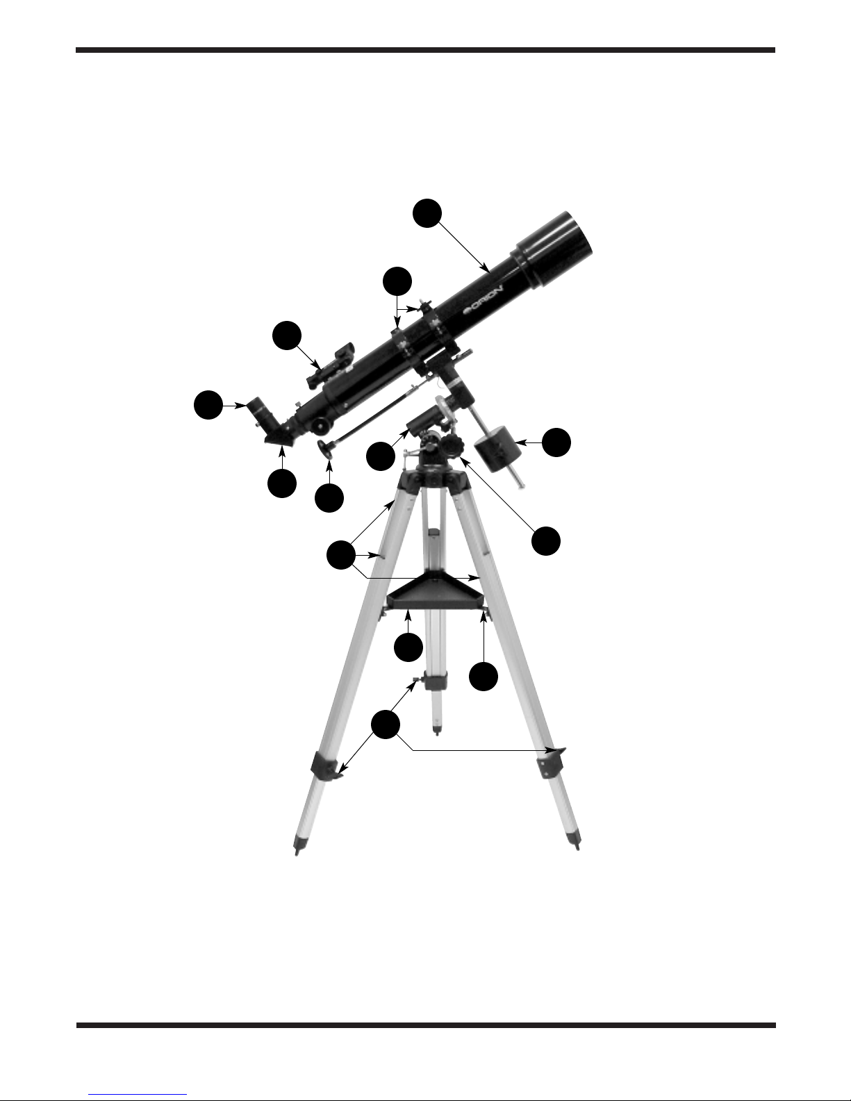
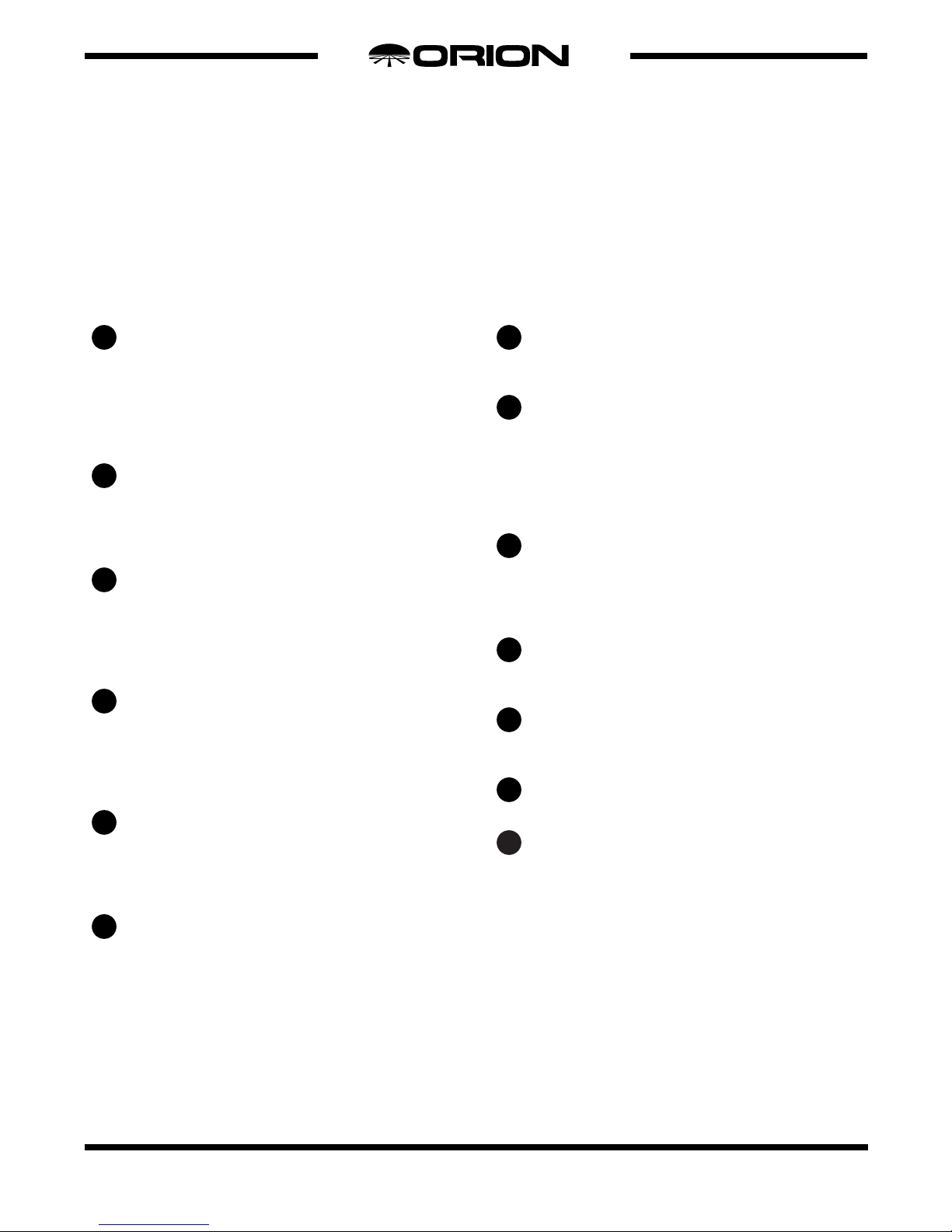
Figure 1. Observer 70 EQ Components
Page 5
Optical tube
This is the main optical component of the telescope.
The glass lens at the front of the tube gathers incoming light and focuses it by bending (or refracting) the
light rays. The tube assembly has several parts built
into it, which are shown and discussed in detail in the
next section.
90° mirror star diagonal
The diagonal contains a mirror that reflects the light
gathered through the optical tube to the eyepiece.The
diagonal is angled to allow for viewing objects that are
high in the sky from a comfortable position.
25mm Explorer II eyepiece
The eyepiece is the part of the telescope that you actu-
ally look through to see things.The focal length of the
eyepiece and the telescope determines the magnifying
power of the telescope. Magnification is discussed in
more detail in the Using Your Telescope section.
EZ Finder II reflex sight
This is a special “finder” that helps you aim the tele-
scope and locate objects in the sky for viewing.The EZ
Finder II generates a red LED “dot” that shows where
your telescope is aimed.The use of the EZ Finder II is
discussed in the Getting Started section.
Equatorial mount
This mount couples the optical tube (1) to the tripod. It
also serves to allow tracking of celestial objects with
the telescope when properly polar aligned. See the
Aligning the Equatorial Mount section for more details.
Tube Rings
These rings attach to the equatorial mount (5) and hold
the optical tube (1).
Counterweight
This counterweight will balance the optical tube (1)
when it is being aimed at celestial objects.
Right ascension slow-motion control cable
This cable, along with the declination slow-motion con-
trol cable (9) is used to make small mov ements in right
ascension when aiming the telescope.Right ascension
is explained in the Aligning the Equatorial Mount section. This cable is also used to “track” stellar objects
and keep them in the field of view
Declination slow-motion cable
This cable, along with the right ascension slow-motion
control cable (8) is used to make small movements in
declination when aiming the telescope. Declination is
explained in the Aligning the Equatorial Mount section.
Tripod legs
These aluminum tripod legs support the telescope and
can extend from 27" to 50" long.
Accessory Tray
This tray is a convenient place for holding extra eye-
pieces and other small pieces of equipment.
Accessory tray bracket
This bracket holds the accessory tray (11) to the tripod.
Leg lock knobs
These knobs lock the tripod legs into place. Loosen
them to lengthen or shorten the tripod legs. Tighten
them once you have the leg at the desired length.Be
certain that all three tripod legs are equally extended to
assure your telescope is level.
13
12
11
10
9
8
7
6
5
4
3
2
1
5
®
The Basic Components of Your Telescope
Figure 1 shows the fully assembled Observer 70 EQ.All the major components of the telescope are described and numbered to
help you identify each part and understand its use. Refer back to this figure when assembling the telescope.
Page 6
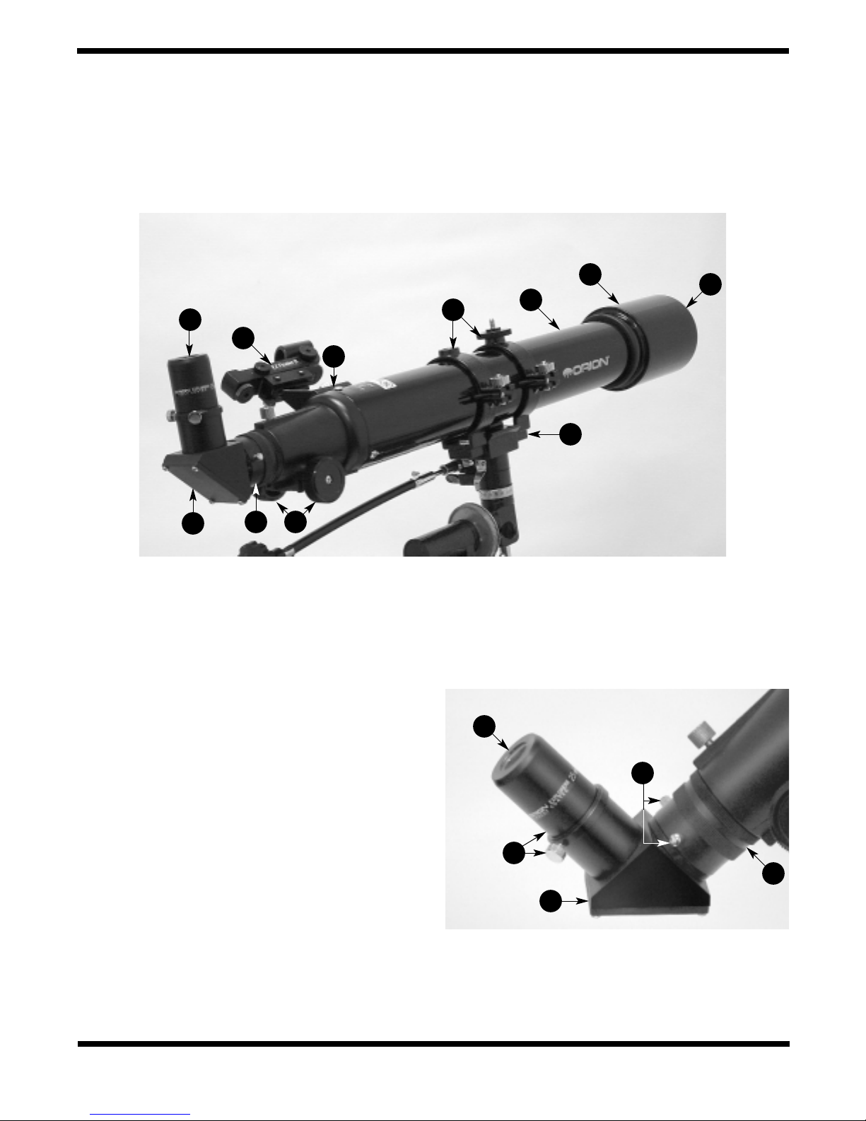
Figure 2a. Optical tube components
6
14
15
17
Observer 70 Telescope Tube
Figure 2b. Observer 70 focuser detail
16
6
19
20
3
21
2
18
1
4
3
2
18
Page 7

7
Objective lens
This is the main optical component of the telescope. It
is an achromatic, fully coated 70mm lens.
Glare/Dew shield
This is a simple “hood” for the objective lens (14) that
prevents dew formation and stray light from hitting the
lens.
Equatorial mount head
The top of the equatorial mount (5). This is where the
optical tube (1) is attached to the mount.
EZ Finder II mounting bracket
The EZ Finder II (4) is secured to this bracket, which
will then be attached to the optical tube (1).
Focuser drawtube
This is where the 90° mirror star diagonal (2), or other
optional diagonal, is inserted. The drawtube is adjusted by the turning the focus wheel (19), which adjusts a
rack-and-pinion system to bring objects into focus.
Focus wheels
These wheels, when turned, move the focuser draw-
tube (18) in or out. Use it to bring things into focus
when you are looking in the eyepiece (3).
Diagonal holder thumbscrews
These two thumbscrews secure the 90° mirror star
diagonal (2) into the focuser drawtube (18). These
should only be loosened to remove or rotate the star
diagonal.
Eyepiece holder thumbscrews
These thumbscrews hold the eyepiece in position.
Tighten them after inserting an eyepiece (3); loosen
them before removing or changing eyepieces.
21
20
19
18
17
16
15
14
Details of the Optical Tube and Components
Figure 2a shows the details of the Optical Tube (1) and its various parts.The optical tube is shown attached to the mount for clarity. Figure 2b is a close up of the focuser with even more detail.
®
Page 8

Figure 3a. Equatorial mount detail.
8
Figure 3b. Observer 70 EQ tripod leg and
mount attachment detail.
22
23
24
Observer 70 Tripod and Mount
25
26
27
7
28
9
30
32
32
29
31
R
ig
h
t A
s
c
e
n
s
io
n
A
x
is
D
e
c
l
i
n
a
t
i
o
n
A
x
i
s
8
Page 9

9
Declination setting circle
This circle will indicate where the telescope is pointing
in the declination axis. Declination is explained in the
Aligning the Equatorial Mount section.
Right ascension lock knob
This knob is loosened when you want to make large
movements in the right ascension axis.Tighten it when
the telescope is in the general area of what you want
to view.
Right ascension setting circle
This circle will indicate where the telescope is pointing
in the right ascension axis.Right ascension is explained
in the Aligning the Equatorial Mount section.
Declination lock knob (opposite side)
This knob is loosened when you want to make large
movements in the declination axis.Tighten it when the
telescope is in the general area of what you want to
view.
Counterweight shaft
This metal shaft holds the counterweight (7).
Counterweight lock knob
This knob should be tightened at all times to keep the
counterweight (7) on the counterweight shaft (26).
Loosen it only to adjust the balance of the telescope as
described in the Balancing the Telescope section.
Latitude scale
This scale gives a general indication of the latitude set-
ting of the equatorial mount (5).
Latitude lock T-bolt
This bolt must be loosened to make adjustments in the
latitude of the telescope.
Latitude adjustment T-bolt
This bolt use used to make adjustments in the latitude
setting of the equatorial mount (5).
Azimuth lock knob
Loosening this knob will allow the equatorial mount (5)
to be adjusted in azimuth (left/right) without changing
the position of the tripod.
Tripod leg attachment screws
These screws attach the tripod legs (10) to the equato-
rial mount (5). Each screw has a wingnut and two
washers.
These items are included with your telescope, but are not
shown in Figures 1, 2 or 3.
10mm Explorer II eyepiece
This is a second, high-power eyepiece, providing 70x magnification.For more details, see the Using your Telescope section.
Dust Cover
Use this to cover the objective lens when the telescope is not
in use.It will prevent dust from gathering on the objective lens .
32
31
30
29
28
27
26
25
24
23
22
Details of the Tripod and Mount
Figure 3a shows a close up of the telescope’s mount and tripod.Important features are pointed out f or greater clarity and detail.
Figure 3b shows close-up detail of the tripod legs (10) attached to the equatorial mount (5).
Page 10

3. Assembly
Assembling the telescope for the first time should take about
30 minutes.You will need any tools other than the ones provided. As a general note, tighten all screws securely to eliminate flexing and wobbling, but be careful not to over-tighten
and thereby strip the threads. Refer to Figures 1 through 3
during the assembly process.
During assembly (and any other time, for that matter), do not
touch the surfaces of the telescope objective lens or the lenses of the finder scope and eyepiece with your fingers.These
optical surfaces have delicate coatings that can easily be
damaged if touched. Never remove any lens assembly from
its housing for any reason, or the product warranty will be
voided.
Begin set-up of the telescope by assembling the tripod and
mount first:
1. Lay the equatorial mount (5) on its side. Attach the tripod
legs (10), one at a time, to the base of the mount by sliding a tripod leg attachment screw (32) through the top of a
leg and through the holes in the base of the mount. The
washers should be on the outside of the tripod legs.
Secure the wing nuts finger-tight. Figure 3b shows a
close-up detail of the screws attaching the tripod legs to
the mount.
2. Install and tighten the leg lock knobs (13) on the bottom
braces of the tripod legs (10). For now, keep the legs at
their shortest (fully retracted) length; you can extend them
to a more desirable length later, once the tripod is completely assembled.
3. Stand the tr ipod and mount upright and spread the tr ipod
legs (10) apart as far as they will go, until the accessory
tray bracket (12) is taut. Connect the accessor y tray (11)
to the accessory tray bracket with the three wing screws
installed in the tray. Push the wing screws up through the
holes in the accessory tray bracket and thread them into
the holes in the accessory tray.
4. Tighten the tripod leg attachment screws (32) at the tops
of the tripod legs so the legs are securely fastened to the
mount. Use the Phillips head screwdriver and/or your fingers to do this.
5. To install the latitude adjustment T-bolt (30), thread it into
the hole in the back of the equatorial mount (5) until tight.
6. Or ient the equator ial mount as it appears in Figure 1, at a
latitude of about 40°, i.e., so the pointer next to the latitude
scale (28) is pointing to the mark at “40.”T o do this , loosen
the latitude lock T-bolt (29), and turn the latitude adjustment T-bolt (30) until the pointer and the “40” line up.Then
retighten the latitude lock T-bolt. The declination (Dec.)
and right ascension (R.A.) axes may need re-positioning
(rotation) as well.Be sure to loosen the R.A.and Dec.lock
knobs (23,25) before doing this. Retighten the R.A. and
Dec. lock knobs once the equatorial mount is properly oriented.
7. Thread the counterweight shaft (25) into the equatorial
mount (5) at the base of the declination axis (shown in
Figure 3a) until tight.
8. Remove the screw and washer on the bottom of the counterweight shaft (26) and slide the counterweight (7) onto
the shaft. Make sure the counterweight lock knob (27) is
adequately loosened to allow the counterweight shaft to
pass through the hole. Position the counterweight about
halfway up the shaft and tighten the lock knob. Replace
the screw and washer on the end of the shaft.
9. Open the tube r ings (6) and remove them from the optical
tube (1).Unthread the hex head screws and washers from
the bottom of the tube rings. Position one of the tube rings
on the top of the equatorial mount head (16) as shown in
Figure 1.Line up the hole in the mount with the hole in the
tube ring, then push the hex head screw, with washers
attached, up through the mount and thread it into the tube
ring.Tighten the screw with the small wrench. Repeat this
for the other tube ring. Note that one of the tube rings has
a small plastic disc with a threaded shaft on it.This is for
attaching a camera and is not used for attaching the tube
rings to the mount.
10.Lay the optical tube (1) in the tube rings (6) at about the
midpoint of the tube’s length.Rotate the tube in the rings
so that the focus wheels (19) are on the underside of the
telescope. Close the rings over the tube and tighten the
knurled ring clamps finger tight to secure the telescope in
position.
10
Figure 4a-d. Proper operation of the equatorial mount requires that the telescope tube be balanced on both the R.A. and Dec. axes. (a)
With the R.A. lock lever released, slide the counterweights along the counterweight shaft until it just counterbalances the tube. (b) When you let
go with both hands, the tube should not drift up or down. (c) With the Dec.lock knob released, loosen the tube ring lock clamps a few turns
and slide the telescope forward or back in the tube rings.(d) When the tube is balanced about the Dec. axis, it will not move when you let go.
abcd
Page 11

11
11. Attach the two slow-motion cables (8,9) to the R.A. and
Dec.worm gear shafts of the equatorial mount (5) by positioning the thumbscrew on the end of the cable over the
indented slot on the worm gear shaft and then tightening
the thumbscrew.We recommend that the shorter cable be
used on either end of the R.A. worm gear shaft and the
longer cable on the Dec.worm gear shaft.
12.Unthread the two knurled metal thumbnuts located on the
optical tube (1) and place the holes on the base of the EZ
Finder II mounting bracket (17) over the two threaded
shafts. Then thread the metal thumbnuts back on the
shafts to secure the mounting bracket to the optical tube.
13. Attach the EZ Finder II reflex sight (4) to the EZ Finder II
mounting bracket (17). Loosen the two secur ing thumbscrews on the EZ Finder II (Figure 5) and slide it onto the
mounting bracket.Tighten the two securing thumbscrews.
You will align the EZ Finder II later, in the Getting Started
section.
14.Insert the chrome barrel of the 90° mirror star diagonal (2)
into the focuser drawtube (18).See Figure 2b. Secure the
star diagonal with the diagonal holder thumbscrews (20).
15.Insert the chrome barrel of the 25mm Explorer II eyepiece
(3) into the open end of the star diagonal (2). Secure the
eyepiece in the diagonal with the eyepiece holder thumbscrews (21).
Your telescope is now fully assembled and should resemble
Figures 1-3.
4. Getting Started
Balancing the Telescope
To insure smooth movement of the telescope on both axes of
the equatorial mount, it is imperative that the optical tube be
properly balanced. We will first balance the telescope with
respect to the right ascension (R.A.) axis and then in the declination (Dec.) axis.
1. Keeping one hand on the telescope optical tube (1), loosen
the R.A. lock knob (23). Make sure the Dec. lock knob (25)
is locked.The telescope should now be able to rotate freely
about the R.A. axis. Rotate it until the counterweight shaft
(26) is parallel to the ground (i.e., horizontal).
2. Now loosen the counterweight lock knob (27) and slide the
weight along the shaft until it exactly counterbalances the
telescope (Figure 4a).That’s the point at which the shaft
remains horizontal even when you let go of the telescope
with both hands (Figure 4b).
3. Retighten the counterweight lock knob.The telescope is
now balanced on the R.A.axis.
4. To balance the telescope on the Dec.axis, first tighten the
R.A. lock knob (23), with the counterweight shaft (26) still
in the horizontal position.
5. With one hand on the telescope optical tube (1), loosen
the Dec.lock knob (25).The telescope should now be able
to move about freely on the Dec.axis. Loosen the knurled
Do You Wear Eyeglasses?
If you wear eyeglasses, you may be able to keep
them on while you observe. In order to do this, your
eyepiece must have enough “eye relief” to allow you
to see the entire field of view with glasses on.You can
try looking through the eyepiece first with your
glasses on and then with them off, to see if the
glasses restrict the view to only a portion of the full
field. If the glasses do restrict the field of view, you
may be able to observe with your glasses off by just
refocusing the telescope to your unaided vision.
If your eyes are astigmatic, images will probably
appear best with glasses on.This is because a
telescope’s focuser can accommodate for
nearsightedness or farsightedness, but not
astigmatism. If you have to wear your glasses while
observing and cannot see the entire field of view, you
may want to purchase additional eyepieces that have
longer eye relief.
Short eye relief
restricts the field of
view for eyeglass
wearers.
Long eye relief
allows full field of
view to be seen
with or without
eyeglasses.
Figure 5. The EZ Finder II reflex sight
Power
knob
Azimuth
adjustment
wheel
Altitude
adjustment
wheel
Thumbscrews
Battery
cover
Page 12

12
ring clamps on the tube rings (6) a few turns, until you can
slide the telescope tube forward and back inside the rings
(this can be aided by using a slight twisting motion on the
optical tube while you push or pull on it) (Figure 4c).
6. Position the telescope in the tube rings (6) so it remains
horizontal when you carefully let go with both hands.This
is the balance point for the optical tube (1) with respect to
the Dec. axis (Figure 4d).
7. Retighten the knurled rings clamps.
The telescope is now balanced on both axes.Now when you
loosen the lock knob (23,25) on one or both axes and manually point the telescope, it should move without resistance and
should not drift from where you point it.
Focusing the Telescope
With the 25mm Explorer II eyepiece (3) inserted into the 90°
mirror star diagonal (2) and secured with the thumbscrews,
aim the optical tube (1) so the front objective lens (14) end is
pointing in the general direction of an object at least 1/4-mile
away. Now, with your fingers, slowly rotate one of the focus
wheels (19) until the object comes into sharp focus.Go a little
bit beyond sharp focus until the image starts to blur again,
then reverse the rotation of the knob , just to mak e sure y ou’ve
hit the exact focus point.
Operating the EZ Finder II Reflex Sight
The EZ Finder II reflex sight (4) (Figure 5) works by projecting
a tiny red dot onto a lens mounted in the front of the unit.
When you look through the EZ Finder II, the red dot will
appear to float in space, helping you locate even the faintest
of deep space objects. The red dot is produced by a lightemitting diode (LED), not a laser beam, near the rear of the
sight. A replaceable 3-volt lithium battery provides the power
for the diode.
To use the EZ Finder II, turn the power knob clockwise until
you hear a “click” indicating that power has been turned on.
With your eyes positioned at a comfortable distance from the
back of the sight, look through the back of the reflex sight with
both eyes open to see the red dot.The intensity of the dot can
be adjusted by turning the power knob.For best results when
stargazing, use the dimmest possible setting that allows you
to see the dot without difficulty.Typically, a dim setting is used
under dark skies and a bright setting is used under light-polluted skies or in daylight.
At the end of your observing session, be sure to turn the
power knob counterclockwise until it clicks off.When the two
white dots on the EZ Finder II’s rail and power knob are lined
up, the EZ Finder II is turned off.
Aligning the EZ Finder II
When the EZ Finder II is properly aligned with the telescope,
an object that is centered on the EZ Finder II’s red dot should
also appear in the center of the field of view of the telescope’s
eyepiece.Alignment of the EZ Finder II is easiest dur ing daylight, before observing at night. Aim the telescope at a distant
object at least 1/4 mile away, such as a telephone pole or
chimney and center it in the telescope’s eyepiece. Now, turn
the EZ Finder II on and look through it.The object will appear
in the field of view near the red dot.
Note:The image in the eyepiece of the Observer 70 will
be reversed from left-to-right.This is normal for a refractor telescope using a mirror star diagonal.
Without moving the telescope, use the EZ Finder II’s azimuth
(left/right) and altitude (up/down) adjustment wheels (Figure
5) to position the red dot on the object in the telescope.
When the red dot is centered on the distant object, check to
make sure that the object is still centered in the telescope’s
field of view. If not, recenter it and adjust the EZ Finder II’s
alignment again. When the object is centered in the telescope’s eyepiece and on the red dot, the EZ Finder II is properly aligned with the telescope. Figure 6 shows how the view
through the EZ Finder may look while you are aligning it.
Once aligned, EZ Finder II will usually hold its alignment even
after being removed and remounted.Otherwise, only minimal
realignment will be needed.
Replacing the EZ Finder II Battery
Should the battery ever need to be replaced, 3-volt lithium
batteries are available from many retail outlets. Remove the
old battery by inserting a small flat-head screwdriver into the
slot on the battery casing (Figure 5) and gently prying open
the case. Then carefully pull back on the retaining clip and
remove the old battery. Do not overbend the retaining clip.
Then slide the new battery under the battery lead with the
positive (+) side facing down and replace the battery casing.
Aligning the Equatorial Mount
When you look at the night sky, you no doubt have noticed
that the stars appear to move slowly from east to west over
time.That apparent motion is caused by the Ear th’s rotation
(from west to east). An equatorial mount (Figure 3a) is
designed to compensate for that motion, allowing you to easily “track” the movement of astronomical objects, thereby
keeping them from drifting out of the telescope’s field of view
while you’re observing.
This is accomplished by slowly rotating the telescope on its
right ascension (R.A.) axis, using only the R.A. slow-motion
cable (8). But first the R.A. axis of the mount must be aligned
Figure 6.
EZ Finder II
superimposes a
tiny red dot on the
sky, showing right
where the
telescope is
pointed.
Page 13

with the Earth’s rotational (polar) axis—a process called polar
alignment.
Understanding Polar Alignment
To understand what you will be doing when polar aligning,
look at Figures 7 and 8.The exaggerated telescope mount in
Figure 7 shows how you will be aligning the Right Ascension
axis (shown in Figure 3a) so that it is parallel to the Earth’s
axis and pointing towards the North Star (Polaris). Figure 8
shows what the polar alignment will mean in terms of your
location on the Earth and other reference points.
The reason for polar alignment is a little tricky to understand;
since the Earth is rotating, stars are moving across the sky in
an arc pattern for most of the world. If you were standing at
the North or South Poles (and were at the top of the rotating
globe), the stars would move in a circular pattern overhead,
never rising or setting. If you were standing on the equator,
the stars would move in straight line overhead. If you faced
east, a star that rose directly in front of you would set directly
behind you in the West.
However, most of us live at a place on the Earth where the
stars rise at one point in the East, move across part of the sky ,
and set at a different part of the Western horizon.This means
that if you were to use an ordinary tripod (which moves in
up/down and left/right motions) to mount your telescope, you
would have a hard time “tracking”stellar objects.This is where
an equatorial mount has the advantage, it may take a little
longer to set up, but the effort is wor th it. Don’t be intimidated
by the setting circles and knobs.It’s actually easier to do than
you might think! Once you’ve practiced a few times, you’ll be
able to set up the equatorial mount easily.
Polar Alignment
For Northern Hemisphere observers, approximate polar
alignment is achieved by pointing the mount’s R.A. axis at
Polaris (also called the North Star).It lies within 1° of the north
celestial pole (NCP), which is an extension of the Earth’s rotational axis out into space. Stars in the Nor ther n Hemisphere
appear to revolve around the NCP.
To find Polaris in the sky, look nor th and locate the patter n of
the Big Dipper (Figure 9). The two stars at the end of the
“bowl” of the Big Dipper point right to Polaris.
Observers in the Southern Hemisphere aren’t so fortunate to
have a bright star so near the south celestial pole (SCP).The
star Sigma Octantis lies about 1° from the SCP, but it is barely visible with the naked eye (magnitude 5.5).
To polar-align the Observer 70 EQ:
1. Level the equatorial mount (5) by adjusting the length of
the three tripod legs (10).
Figure 9. To find Polaris in the night sky, look north and find the
Big Dipper.Extend an imaginar y line from the two "Pointer Stars" in
the bowl of the Big Dipper.Go about five times the distance
between those stars and you'll reach Polaris, which lies within 1° of
the north celestial pole (NCP).
13
Figure 7. When properly polar-aligned, the equatorial mount can
easily “track” objects by compensating for the rotation of the earth.
EQ mount moves in the opposite
Figure 8. Polar alignment of the Observer 70 EQ is easily done
by pointing the telescope’s right ascension axis at Polaris (The
North Star).
Big Dipper
(in Ursa Major)
Little Dipper
(in Ursa Minor)
Cassiopeia
N.C.P.
P
ointe
r
S
ta
rs
Polaris
direction of the Earth's rotation.
to Polaris
Right Ascension Axis
E
q
u
a
r
t
o
C
e
l
e
s
t
i
a
l
E
q
u
a
t
o
r
o
t
E
e
l
q
o
u
P
a
°
0
9
Horizon
S N
S
Celestial
Equator
t
o
r
ght Asce
i
R
W
W
Angle from the ground
to the North Star is the
same as your latitude.
Your EQ mount's latitude
should match this angle.
nsion Axi
s
Polaris
(The North Star)
N
E
E
Page 14

14
2. Loosen the latitude lock T-bolt (29). Turn the latitude
adjustment T-bolt (30) and tilt the mount until the pointer
on the latitude scale is set at the latitude of your observing
site.If you don’t know your latitude, consult a geographical
atlas to find it. For example, if your latitude is 35° North,
set the pointer to 35.Then retighten the latitude lock T-bolt.
The latitude setting should not have to be adjusted again
unless you move to a different viewing location some distance away.
3. Loosen the Dec. lock knob (25) and rotate the telescope
optical tube (1) until it is parallel with the R.A. axis, as it is
in Figure 1. The pointer on the Dec. setting circle (22)
should read 90°. Retighten the Dec. lock lever.
4. Loosen the azimuth lock knob (31) at the base of the
equatorial mount (5) and rotate the mount so the telescope tube (and R.A. axis) points roughly at Polaris.If you
cannot see Polaris directly from your observing site, consult a compass and rotate the mount so the telescope
points North. Retighten the azimuth lock knob.
The equatorial mount is now polar aligned.
From this point on in your observing session,you should
not make any further adjustments in the azimuth or the
latitude of the mount, nor should you move the tripod.
Doing so will undo the polar alignment. The telescope
should be moved only about its R.A. and Dec. axes.
Use of the R.A. and Dec.
Slow-Motion Control Cables
The R.A. and Dec. slow-motion control cables (8,9) allow fine
adjustment of the telescope’s position to center objects within
the field of view. Before you can use the cables, you must
manually “slew”the mount to point the telescope in the vicinity of the desired target. Do this by loosening the R.A. and
Dec. lock knobs (23,25) and moving the telescope about the
mount’s R.A. and Dec. axes. Once the telescope is pointed
somewhere close to the object to be viewed, retighten the
mount’s R.A.and Dec. lock knobs.
The object should now be visible somewhere in the EZ Finder
II (4). If it isn’t, use the slow-motion controls to scan the surrounding area of sky. When the object is visible in the EZ
Finder II, use the slow-motion controls to center it. Now, look
in the telescope’s eyepiece. If the EZ Finder II is properly
aligned, the object should be visible somewhere in the field of
view. Once the object is visible in the eyepiece, use the slowmotion controls to center it in the field of view.
The Dec. slow-motion control cable (9) can move the telescope a maximum of 25°. This is because the Dec. slowmotion mechanism has a limited range of mechanical travel.
(The R.A. slow-motion mechanism has no limit to its amount
of travel.) If you can no longer rotate the Dec.control cable in
a desired direction, you have reached the end of travel, and
the slow-motion mechanism must be reset. This is done by
first rotating the control cable several turns in the opposite
direction from which it was originally being turned.Then, manually slew the telescope closer to the object you wish to
observe (remember to first loosen the Dec. lock knob (25)).
You should now be able to use the Dec. slow-motion control
cable again to fine adjust the telescope’s position.
Tracking Celestial Objects
When you observe a celestial object through the telescope,
you’ll see it drift slowly across the field of view.To keep it in
the field, if your equatorial mount is polar aligned, just turn the
R.A. slow-motion control cable clockwise. The Dec. slowmotion control cable is not needed for tracking. Objects will
appear to move faster at higher magnifications, because the
field of view is narrower.
Optional Electronic Drives for
Automatic Tracking
An optional DC electronic drive can be mounted on the R.A.axis
of the equatorial mount to provide hands-free tracking.Objects
will then remain stationary in the field of view without any manual adjustment of the R.A.slow-motion control cable (8).
Understanding the Setting Circles
The setting circles on an equatorial mount enable you to
locate celestial objects by their “celestial coordinates”.Every
object resides in a specific location on the “celestial sphere”.
That location is denoted by two numbers: its right ascension
(R.A.) and declination (Dec.). In the same way, every location
on Earth can be described by its longitude and latitude. R.A.
is similar to longitude on Earth, and Dec. is similar to latitude.
The R.A.and Dec. values for celestial objects can be found in
any star atlas or star catalog.
The mount’s R.A.setting circle (24) is scaled in hours, from 1
through 24, with small marks in between representing 10minute increments.The numbers closest to the R.A. axis gear
apply to viewing in the Southern Hemisphere, while the numbers above them apply to viewing in the Northern Hemisphere.
The Dec. setting circle (22) is scaled in degrees, with each
mark representing 2.5° increments. Values of Dec. coordinates range from +90° to -90°. The 0° mark indicates the
celestial equator.When the telescope is pointed nor th of the
celestial equator, v alues of the Dec.setting circle are positive,
while when the telescope is pointed south of the celestial
equator, values of the Dec. setting circle are negative.
So, the coordinates for the Orion Nebula listed in a star atlas
will look like this:
R.A. 5h 35.4m Dec. –5° 27'
That’s 5 hours and 35.4 minutes in right ascension, and -5
degrees and 27 arc-minutes in declination (there are 70 arcminutes in 1 degree of declination).
Before you can use the setting circles to locate objects, the
mount must be correctly polar aligned, and the R.A.setting circle must be calibrated.The Dec. setting circle has been permanently calibrated at the factory, and should read 90° whenever the telescope optical tube is parallel with the R.A.axis.
Calibrating the Right Ascension Setting Circle
1. Identify a bright star in the sky near the celestial equator
(Dec. = 0°) and look up its coordinates in a star atlas.
Page 15

15
2. Loosen the R.A. and Dec. lock knobs (23, 25) on the equatorial mount (5), so the telescope optical tube can move
freely.
3. Point the telescope at the bright star whose coordinates
you know. Lock the R.A. and Dec.lock knobs.Center the
star in the telescope’s field of view with the slow-motion
control cables.
4. Rotate the setting circle until the metal arrow indicates the
R.A. coordinate listed in the star atlas for the object.
Finding Objects With the Setting Circles
Now that both setting circles are calibrated, look up in a star
atlas the coordinates of an object you wish to view.
Loosen the Dec. lock knob (25) and rotate the telescope until
the Dec. value from the star atlas matches the reading on the
Dec.setting circle (22). Remember that values of the Dec.setting circle are positive when the telescope is pointing north of
the celestial equator (Dec. = 0°), and negative when the telescope is pointing south of the celestial equator.Retighten the
lock knob.
Loosen the R.A. lock knob (23) and rotate the telescope until
the R.A. value from the star atlas matches the reading on the
R.A. setting circle (24). Remember to use the upper set of
numbers on the R.A.setting circle. Retighten the lock knob.
Most setting circles are not accurate enough to put an object
dead-center in the telescope’s eyepiece, but they should
place the object somewhere within the field of view of the EZ
Finder II (4), assuming the equatorial mount is accurately
polar aligned. Use the slow-motion controls to center the
object in the EZ Finder II, and it should appear in the telescope’s field of view.
The R.A. setting circle must be re-calibrated every time you
wish to locate a new object.Do so by calibrating the setting circle for the centered object before moving on to the next one.
Confused About Pointing the Telescope?
Beginners occasionally experience some confusion about
how to point the telescope overhead or in other directions.In
Figure 1 the telescope is pointed north, as it would be during
polar alignment. The counterweight shaft is or iented downward. But it will not look like that when the telescope is pointed in other directions. Let’s say you want to view an object
that is directly overhead, at the zenith.How do you do it?
One thing you DO NOT do is make any adjustment to the latitude adjustment T-bolt (30).That will nullify the mount’s polar
alignment. Remember, once the mount is polar aligned, the
telescope should be moved only on the R.A.and Dec. axes.
To point the scope overhead, first loosen the R.A.lock knob
(23) and rotate the telescope on the R.A. axis until the counterweight shaft is horizontal (parallel to the ground). Then
loosen the Dec. lock knob (25) and rotate the telescope until
it is pointing straight overhead.The counterweight shaft (26)
is still horizontal.Then retighten both lock knobs.
Similarly, to point the telescope directly south, the counterweight shaft should again be horizontal. Then you simply
rotate the scope on the Dec. axis until it points in the south
direction.
What if you need to aim the telescope directly north, but at an
object that is nearer to the horizon than Polaris? You can’t do
it with the counterweight down as pictured in Figure 1.Again,
you have to rotate the scope in R.A. so the counterweight
shaft is positioned horizontally.Then rotate the scope in Dec.
so it points to where you want it near the horizon.
To point the telescope to the east or west, or in other directions, you rotate the telescope on its R.A. and Dec. axes.
Depending on the altitude of the object you want to observe,
the counterweight shaft will be oriented somewhere between
vertical and horizontal.
Figure 10 illustrates how the telescope will look pointed at the
four cardinal directions—north, south, east, and west
The key things to remember when pointing the telescope is
that a) you only move it in R.A.and Dec., not in azimuth or latitude (altitude), and b) the counterweight and shaft will not
always appear as it does in Figure 1.In fact, it almost never
will!
5. Using Your Telescope
Choosing an Observing Site
When selecting a location for observing, get as far away as
possible from direct artificial light such as street lights, porch
lights, and automobile headlights.The glare from these lights
will greatly impair your dark-adapted night vision.Set up on a
grass or dirt surface, not asphalt, because asphalt radiates
more heat, which disturbs the surrounding air and degrades
the images seen through the telescope. Avoid viewing over
Figure 10a-d. These illustrations show the telescope pointed in the four cardinal directions (a) north, (b) south, (c) east, (d) west.Note
that the tripod and mount have not been moved;only the telescope tube has been moved on the R.A. and Dec. axes.
abcd
Page 16

rooftops and chimneys, as they often have warm air currents
rising from them. Similarly, avoid observing from indoors
through an open (or closed) window, because the temperature difference between the indoor and outdoor air will cause
image blurring and distortion.
If at all possible, escape the light-polluted city sky and head
for darker country skies.You’ll be amazed at how many more
stars and deep-sky objects are visible in a dark sky!
“Seeing” and Transparency
Atmospheric conditions vary significantly from night to night.
“Seeing” refers to the steadiness of the Earth’s atmosphere at
a given time.In conditions of poor seeing, atmospheric turbulence causes objects viewed through the telescope to “boil”.
If, when you look up at the sky with your nak ed e yes , the stars
are twinkling noticeably, the seeing is bad and you will be limited to viewing with low powers (bad seeing affects images at
high powers more sev erely).Planetary observing may also be
poor.
In conditions of good seeing, star twinkling is minimal and
images appear steady in the eyepiece. Seeing is best overhead, worst at the horizon. Also, seeing generally gets better
after midnight, when much of the heat absorbed by the Earth
during the day has radiated off into space.
Especially important for observing faint objects is good “trans-
parency”—air free of moisture, smoke, and dust. All tend to
scatter light, which reduces an object’s brightness. Transparency is judged by the magnitude of the faintest stars you can
see with the unaided eye (6th magnitude or fainter is desir able).
If you cannot see stars of magnitude 3.5 or dimmer then conditions are poor.Magnitude is a measure of how bright a star
is—the brighter a star is, the lower its magnitude will be. A
good star to remember for this is Megrez (mag.3.4), which is
the star in the “Big Dipper” connecting the handle to the “dip-
per”. If you cannot see Megrez, then you have fog, haze,
clouds, smog, or other conditions that are hindering your
viewing Figure 11).
Eyepiece Selection
By using eyepieces of different focal lengths, it is possible to
attain many magnifications or powers with the Observer 70.
Your telescope comes with two Explorer II eyepieces (Figure
12): a 25mm, which gives a magnification of 28x, and a
10mm, which gives a magnification of 70x. Other eyepieces
can be used to achieve higher or lower powers. It is quite
common for an observer to own five or more eyepieces to
access a wide range of magnifications.
To calculate the magnification, or power, of a telescope-eyepiece combination, simply divide the focal length of the telescope by the focal length of the eyepiece:
Telescope Focal Length (mm)
Magnification =
Eyepiece Focal Length (mm)
For example , the Observer 70 EQ, which has a f ocal length of
700mm, used in combination with the 25mm eyepiece, yields
a magnification of:
700mm
= 28x
25mm
Whatever you choose to view, always start by inserting your
lowest-power (longest focal length) eyepiece to locate and
center the object. Low magnification yields a wide field of
view, which shows a larger area of sky in the eyepiece.This
makes finding and centering an object much easier.Trying to
Figure 11. Megrez connects the Big Dipper’s handle to it's “pan”.
It is a good guide to how conditions are. If you can not see Megrez
(a 3.4 mag star) then conditions are poor.
16
Light Pollution
Most of us live where city lights interfere with our view
of the heavens.As our metropolitan areas have become
more developed, the scourge of light pollution has
spread, washing out many stars and nonstellar celestial
objects from our sight. Faint deep sky objects become
difficult or impossible to see through the murk of light
pollution. Even bright nebulas like the Orion and Lagoon
Nebulas lose much of their delicate detail.The Moon
and planets are not affected;they require steady air
more than dark skies, so they remain good targets for
city-dwelling observers.
The International Dark-Sky Association is waging the
fight against light pollution.The IDSA was founded in
1988 with the mission of educating the public about the
adverse impact that light pollution has on the night sky
and astronomy.Through educational and scientific
means, the nonprofit IDA works to raise awareness
about the problem and about measures that can be
taken to solve it.
Do you need help dealing with local officials to control
street or building lighting in your area? The IDA’s exten-
sive support materials can show you how. Help preserve dark skies, join the IDA today! For information,
write to IDA, 3225 N.First Ave., Tuscon, AZ 85719-2103
or visit their website: www.darksky.org.
The best way to avoid immediate problems with light pollution, howev er, is to take you telescope to where there
are dark skies.You will be amazed at how many stars
you can see when you get away from the city lights.
1.9
4.9
2.4
1.9
2.4
1.7
3.4
2.5
Page 17

17
find and center objects with a high power (narrow field of
view) eyepiece is like trying to find a needle in a haystack!
Once you’ve centered the object in the eyepiece, you can
switch to a higher magnification (shorter focal length) eyepiece, if you wish.This is recommended for small and bright
objects, like planets and double stars.The Moon also takes
higher magnifications well.
The best rule of thumb with eyepiece selection is to start with
a low power, wide-field eyepiece, and then work your way up
in magnification. If the object looks better, try an even higher
magnification eyepiece.If the object looks worse, then back
off the magnification a little by using a lower-power eyepiece.
What to Expect
So what will you see with your telescope? You should be able
to see bands on Jupiter, the rings of Saturn, craters on the
Moon, the waxing and waning of Venus, and many bright
deep-sky objects. Do not expect to see color as you do in
NASA photos, since those are taken with long-exposure cameras and have “false color” added. Our eyes are not sensitive
enough to see color in deep-sky objects except in a fe w of the
brightest ones.
Remember that you are seeing these objects using your own
telescope with your own eyes! The object you see in your e yepiece is in real-time, and not some conveniently provided
image from an expensive space probe. Each session with
your telescope will be a learning experience. Each time you
work with your telescope it will get easier to use, and stellar
objects will become easier to find.Take it from us, there is big
difference between looking at a well-made full-color NASA
image of a deep-sky object in a lit room during the daytime,
and seeing that same object in your telescope at night. One
can merely be a pretty image someone gave to you.The other
is an experience you will never forget!
Objects to Observe
Now that you are all set up and ready to go, one critical decision must be made: what to look at?
A.The Moon
With its rocky surface, the Moon is one of the easiest and most
interesting targets to view with your telescope.Lunar craters,
marias, and even mountain ranges can all be clearly seen
from a distance of 238,000 miles away! With its ever-changing
phases, you’ll get a new view of the Moon every night. The
best time to observe our one and only natural satellite is during a partial phase, that is, when the Moon is NOT full.During
partial phases, shadows are cast on the surface, which reveal
more detail, especially right along the border between the dark
and light portions of the disk (called the “terminator”). A full
Moon is too bright and devoid of surface shadows to yield a
pleasing view. Make sure to obser ve the Moon when it is well
above the horizon to get the sharpest images.
Use an optional Moon filter to dim the Moon when it is very
bright. It simply threads onto the bottom of the eyepieces (you
must first remove the eyepiece from the focuser to attach a filter).You’ll find that the Moon filter improves viewing comfort,
and also helps to bring out subtle features on the lunar surface.
B.The Sun
You can change your nighttime telescope into a daytime Sun
viewer by installing an optional full-aperture solar filter over
the front opening of the Observer 70.The primary attraction is
sunspots, which change shape, appearance, and location
daily. Sunspots are directly related to magnetic activity in the
Sun. Many observers like to make drawings of sunspots to
monitor how the Sun is changing from day to day.
Important Note: Do not look at the Sun with any optical
instrument without a professionally made solar filter, or
permanent eye damage could result.
C.The Planets
The planets don’t stay put like the stars, so to find them you
should refer to Sky Calendar at our website (telescope.com),
or to charts published monthly in Astronomy, Sky & Tele-
scope, or other astronomy magazines.Venus, Mars, Jupiter,
and Saturn are the brightest objects in the sky after the Sun
and the Moon.Your Obser ver 70 is capable of showing you
these planets in some detail.Other planets may be visible but
Magnification Limits
Every telescope has a useful magnification limit of
about 2X per millimeter of aperture. This comes to
140X for the Observer 70. Some telescope
manufacturers will use misleading claims of excess
magnification, such as “See distant galaxies at 640X!”.
While such magnifications are technically possible, the
actual image at that magnification would be an
indistinct blur.
Moderate magnifications are what give the best views.
It is better to view a small, but bright and detailed
image than a dim, unclear, oversized image.
Figure 12.
The 10mm and 25mm
Explorer II eyepieces.
Page 18

18
will likely appear star-like.Because planets are quite small in
apparent size, optional higher-power eyepieces are recommended and often needed for detailed observations. Not all
the planets are generally visible at any one time.
JUPITER: The largest planet, Jupiter, is a great subject for
observation. You can see the disk of the giant planet and
watch the ever-changing positions of its four largest moons—
Io, Callisto, Europa, and Ganymede.
SATURN: The r inged planet is a breathtaking sight when it is
well positioned.The tilt angle of the rings varies over a period
of many years; sometimes they are seen edge-on, while at
other times they are broadside and look like giant “ears” on
each side of Saturn’s disk. A steady atmosphere (good seeing) is necessary for a good view. You will probably see a
bright “star” close by, which is Saturn’s brightest moon, Titan.
VENUS: At its brightest, Venus is the most luminous object in
the sky, excluding the Sun and the Moon. It is so bright that
sometimes it is visible to the naked eye during full daylight!
Ironically, Venus appears as a thin crescent, not a full disk,
when at its peak brightness.Because it is so close to the Sun,
it never wanders too far from the morning or evening horizon.
No surface markings can be seen on Venus, which is always
shrouded in dense clouds.
MARS: The Red Planet makes its closest approach to Ear th
every two years. Dur ing close approaches you’ll see a red
disk, and may be able to see the polar ice cap.
D.The Stars
Stars will appear like twinkling points of light. Even powerful
telescopes cannot magnify stars to appear as more than a
point of light.You can, however , enjo y the diff erent colors of the
stars and locate many pretty double and multiple stars.The
famous “Double-Double” in the constellation Lyra and the gorgeous two-color double star Albireo in Cygnus are favorites.
Defocusing a star slightly can help bring out its color.
E. Deep-Sky Objects
Under dark skies, you can observe a wealth of fascinating
deep-sky objects, including gaseous nebulas, open and globular star clusters, and a variety of different types of galaxies.
Most deep-sky objects are very faint, so it is important that
you find an observing site well away from light pollution.Take
plenty of time to let your eyes adjust to the darkness.Do not
expect these subjects to appear like the photographs you see
in books and magazines; most will look like dim gray
smudges. Our eyes are not sensitive enough to see color in
deep-sky objects except in a few of the brightest ones. But as
you become more experienced and your observing skills get
sharper, you will be able to ferret out more and more subtle
details and structure.
To find deep sky objects in the sky, it is best to consult a star
chart and planisphere. These guides will help you locate the
brightest and best deep-sky objects for viewing with your
Observer 70.
6. Care and Maintenance
If you give your telescope reasonable care, it will last a lifetime. Store it in a clean, dry, dust free place, safe from rapid
changes in temperature and humidity. Do not store the telescope outdoors, although storage in a garage or shed is OK.
Small components like eyepieces and other accessories
should be kept in a protective box or storage case. Keep the
caps on the front of the telescope and on the focuser drawtube when not in use.
Your Obser ver 70 telescope requires very little mechanical
maintenance.The optical tube is aluminum and has a smooth
painted finish that is fairly scratch resistant. If a scratch does
appear, it will not harm the telescope.
Cleaning Lenses
Any quality optical lens cleaning tissue and optical lens cleaning fluid specifically designed for multi-coated optics can be
used to clean the Observer 70’s objective lens (14) and the
exposed lenses of your eyepieces. Never use regular glass
cleaner or cleaning fluid designed for eyeglasses
Before cleaning with fluid and tissue, blo w any loose particles
off the lens with a blower bulb or compressed air.Then apply
some cleaning fluid to a tissue, never directly on the optics.
Wipe the lens gently in a circular motion, then remove any
excess fluid with a fresh lens tissue. Oily fingerprints and
smudges may be removed using this method. Use caution—
rubbing too hard may scratch the lens.For the larger surface
of the objective lens, clean only a small area at a time, using
a fresh lens tissue on each area. Never reuse tissues.
7. Specifications
Optical tube: Aluminum
Objective lens diameter: 70mm
Objective lens: Achromatic, air-spaced, fully coated
Focal length: 700mm
Focal ratio: f/10.0
Focuser: Rack and pinion, accepts 1.25" eyepieces and
accessories
Eyepieces: 25mm and 10mm Explorer II eyepieces, fully
coated 1.25"
Magnification with supplied eyepieces: 28x (with 25mm) and
70x (with 10mm)
Tripod: Aluminum
Mount: EQ-1, Ger man equator ial
Star diagonal: Mirror, 1.25"
Finder: EZ Finder II reflex sight
Motor drive: Optional
Weight: 10.5 lbs.
Page 19

19
Page 20

20
One-Year Limited Warranty
This Orion ObserverTM70 EQ is warranted against defects in materials or workmanship for a
period of one year from the date of purchase.This warranty is for the benefit of the original retail
purchaser only. During this warranty period Orion Telescopes & Binoculars will repair or
replace, at Orion’s option, any warranted instrument that proves to be defective, provided it is
returned postage paid to: Orion Warranty Repair , 89 Hangar Way, Watsonville, CA 95076.If the
product is not registered, proof of purchase (such as a copy of the original invoice) is required.
This warranty does not apply if, in Orion’s judgment, the instrument has been abused, mishan-
dled, or modified, nor does it apply to normal wear and tear.This warranty gives you specific
legal rights, and you may also ha ve other rights, which vary from state to state.For further warranty service information, contact: Customer Service Department, Orion Telescopes &
Binoculars, P. O.Box 1815, Santa Cruz, CA 95061; (800)676-1343.
Orion Telescopes & Binoculars
Post Office Box 1815, Santa Cruz, CA 95061
Customer Support Help Line (800)676-1343 • Day or Evening
 Loading...